EP1591182A2 - Drill bit, drilling system and method to determine the electromagnetical environment of a drill bit - Google Patents
Drill bit, drilling system and method to determine the electromagnetical environment of a drill bit Download PDFInfo
- Publication number
- EP1591182A2 EP1591182A2 EP05102946A EP05102946A EP1591182A2 EP 1591182 A2 EP1591182 A2 EP 1591182A2 EP 05102946 A EP05102946 A EP 05102946A EP 05102946 A EP05102946 A EP 05102946A EP 1591182 A2 EP1591182 A2 EP 1591182A2
- Authority
- EP
- European Patent Office
- Prior art keywords
- drill bit
- sensor
- coil
- sensor device
- drilling
- Prior art date
- Legal status (The legal status is an assumption and is not a legal conclusion. Google has not performed a legal analysis and makes no representation as to the accuracy of the status listed.)
- Withdrawn
Links
- 238000005553 drilling Methods 0.000 title claims abstract description 127
- 238000000034 method Methods 0.000 title claims abstract description 70
- 238000011156 evaluation Methods 0.000 claims abstract description 114
- 230000005291 magnetic effect Effects 0.000 claims abstract description 76
- 238000001514 detection method Methods 0.000 claims abstract description 50
- 239000000463 material Substances 0.000 claims abstract description 45
- 239000004065 semiconductor Substances 0.000 claims abstract description 23
- 239000003302 ferromagnetic material Substances 0.000 claims abstract description 18
- 238000005259 measurement Methods 0.000 claims description 49
- 230000005294 ferromagnetic effect Effects 0.000 claims description 24
- 230000011664 signaling Effects 0.000 claims description 23
- 238000005520 cutting process Methods 0.000 claims description 15
- 230000003628 erosive effect Effects 0.000 claims description 14
- 238000004891 communication Methods 0.000 claims description 13
- 230000008054 signal transmission Effects 0.000 claims description 13
- 230000008569 process Effects 0.000 claims description 12
- XLYOFNOQVPJJNP-UHFFFAOYSA-N water Substances O XLYOFNOQVPJJNP-UHFFFAOYSA-N 0.000 claims description 11
- 230000006978 adaptation Effects 0.000 claims description 10
- 238000006243 chemical reaction Methods 0.000 claims description 10
- 230000004044 response Effects 0.000 claims description 6
- 229910000831 Steel Inorganic materials 0.000 claims description 5
- 239000010959 steel Substances 0.000 claims description 5
- 238000005065 mining Methods 0.000 claims description 3
- 239000000758 substrate Substances 0.000 claims description 2
- 230000000007 visual effect Effects 0.000 claims 1
- 230000005284 excitation Effects 0.000 abstract description 13
- 230000005855 radiation Effects 0.000 abstract 1
- XEEYBQQBJWHFJM-UHFFFAOYSA-N Iron Chemical compound [Fe] XEEYBQQBJWHFJM-UHFFFAOYSA-N 0.000 description 164
- 229910052742 iron Inorganic materials 0.000 description 80
- 230000003014 reinforcing effect Effects 0.000 description 70
- 230000000593 degrading effect Effects 0.000 description 66
- 230000008859 change Effects 0.000 description 64
- 230000008878 coupling Effects 0.000 description 37
- 238000010168 coupling process Methods 0.000 description 37
- 238000005859 coupling reaction Methods 0.000 description 37
- 230000001939 inductive effect Effects 0.000 description 33
- 230000006870 function Effects 0.000 description 30
- 229910052751 metal Inorganic materials 0.000 description 25
- 239000002184 metal Substances 0.000 description 25
- 230000035945 sensitivity Effects 0.000 description 18
- 230000002787 reinforcement Effects 0.000 description 16
- 238000010586 diagram Methods 0.000 description 12
- 230000004907 flux Effects 0.000 description 11
- 239000011159 matrix material Substances 0.000 description 11
- 230000035699 permeability Effects 0.000 description 11
- 239000010432 diamond Substances 0.000 description 9
- 230000008901 benefit Effects 0.000 description 8
- 229910003460 diamond Inorganic materials 0.000 description 8
- 238000013459 approach Methods 0.000 description 7
- 230000005540 biological transmission Effects 0.000 description 7
- 238000000691 measurement method Methods 0.000 description 7
- 230000010355 oscillation Effects 0.000 description 7
- 230000002829 reductive effect Effects 0.000 description 7
- 238000004804 winding Methods 0.000 description 7
- 229910000859 α-Fe Inorganic materials 0.000 description 6
- 238000004364 calculation method Methods 0.000 description 5
- 239000003990 capacitor Substances 0.000 description 5
- 150000001875 compounds Chemical class 0.000 description 5
- 239000004567 concrete Substances 0.000 description 5
- 239000004020 conductor Substances 0.000 description 5
- 238000013461 design Methods 0.000 description 5
- 238000001914 filtration Methods 0.000 description 5
- 230000001360 synchronised effect Effects 0.000 description 5
- 238000012546 transfer Methods 0.000 description 5
- 230000000694 effects Effects 0.000 description 4
- 238000002847 impedance measurement Methods 0.000 description 4
- 239000000203 mixture Substances 0.000 description 4
- 230000000704 physical effect Effects 0.000 description 4
- 238000004382 potting Methods 0.000 description 4
- 230000009467 reduction Effects 0.000 description 4
- 239000000126 substance Substances 0.000 description 4
- 230000015556 catabolic process Effects 0.000 description 3
- 230000007423 decrease Effects 0.000 description 3
- 238000006731 degradation reaction Methods 0.000 description 3
- 230000000779 depleting effect Effects 0.000 description 3
- 230000005611 electricity Effects 0.000 description 3
- 238000005516 engineering process Methods 0.000 description 3
- 238000004519 manufacturing process Methods 0.000 description 3
- 238000012986 modification Methods 0.000 description 3
- 230000004048 modification Effects 0.000 description 3
- 230000003287 optical effect Effects 0.000 description 3
- 230000035515 penetration Effects 0.000 description 3
- 239000004033 plastic Substances 0.000 description 3
- 239000000523 sample Substances 0.000 description 3
- 238000004088 simulation Methods 0.000 description 3
- 230000003068 static effect Effects 0.000 description 3
- 238000005299 abrasion Methods 0.000 description 2
- 239000006061 abrasive grain Substances 0.000 description 2
- 230000015572 biosynthetic process Effects 0.000 description 2
- 238000010276 construction Methods 0.000 description 2
- 238000011109 contamination Methods 0.000 description 2
- 239000010949 copper Substances 0.000 description 2
- 230000001419 dependent effect Effects 0.000 description 2
- 230000001066 destructive effect Effects 0.000 description 2
- 238000006073 displacement reaction Methods 0.000 description 2
- 210000003128 head Anatomy 0.000 description 2
- 230000006698 induction Effects 0.000 description 2
- 238000009659 non-destructive testing Methods 0.000 description 2
- 230000000737 periodic effect Effects 0.000 description 2
- 230000001105 regulatory effect Effects 0.000 description 2
- 238000012360 testing method Methods 0.000 description 2
- KQZLRWGGWXJPOS-NLFPWZOASA-N 1-[(1R)-1-(2,4-dichlorophenyl)ethyl]-6-[(4S,5R)-4-[(2S)-2-(hydroxymethyl)pyrrolidin-1-yl]-5-methylcyclohexen-1-yl]pyrazolo[3,4-b]pyrazine-3-carbonitrile Chemical compound ClC1=C(C=CC(=C1)Cl)[C@@H](C)N1N=C(C=2C1=NC(=CN=2)C1=CC[C@@H]([C@@H](C1)C)N1[C@@H](CCC1)CO)C#N KQZLRWGGWXJPOS-NLFPWZOASA-N 0.000 description 1
- 238000012935 Averaging Methods 0.000 description 1
- RYGMFSIKBFXOCR-UHFFFAOYSA-N Copper Chemical compound [Cu] RYGMFSIKBFXOCR-UHFFFAOYSA-N 0.000 description 1
- 229910000640 Fe alloy Inorganic materials 0.000 description 1
- 239000004952 Polyamide Substances 0.000 description 1
- 229910001069 Ti alloy Inorganic materials 0.000 description 1
- 230000009471 action Effects 0.000 description 1
- 230000003321 amplification Effects 0.000 description 1
- 230000009286 beneficial effect Effects 0.000 description 1
- 238000005352 clarification Methods 0.000 description 1
- 239000002131 composite material Substances 0.000 description 1
- 229940125877 compound 31 Drugs 0.000 description 1
- 230000003750 conditioning effect Effects 0.000 description 1
- 239000000498 cooling water Substances 0.000 description 1
- 229910052802 copper Inorganic materials 0.000 description 1
- 210000003298 dental enamel Anatomy 0.000 description 1
- 238000009826 distribution Methods 0.000 description 1
- 230000005684 electric field Effects 0.000 description 1
- 230000002349 favourable effect Effects 0.000 description 1
- 239000000835 fiber Substances 0.000 description 1
- 239000003733 fiber-reinforced composite Substances 0.000 description 1
- 238000005206 flow analysis Methods 0.000 description 1
- 229910000704 hexaferrum Inorganic materials 0.000 description 1
- 230000001976 improved effect Effects 0.000 description 1
- 229910052500 inorganic mineral Inorganic materials 0.000 description 1
- 238000011835 investigation Methods 0.000 description 1
- 230000000670 limiting effect Effects 0.000 description 1
- 238000012886 linear function Methods 0.000 description 1
- 230000005389 magnetism Effects 0.000 description 1
- 238000012423 maintenance Methods 0.000 description 1
- 239000007769 metal material Substances 0.000 description 1
- 239000011707 mineral Substances 0.000 description 1
- 238000003012 network analysis Methods 0.000 description 1
- 210000001331 nose Anatomy 0.000 description 1
- 238000003199 nucleic acid amplification method Methods 0.000 description 1
- 238000004806 packaging method and process Methods 0.000 description 1
- 230000036961 partial effect Effects 0.000 description 1
- 244000052769 pathogen Species 0.000 description 1
- 230000001717 pathogenic effect Effects 0.000 description 1
- 230000010363 phase shift Effects 0.000 description 1
- 229920002647 polyamide Polymers 0.000 description 1
- 238000003825 pressing Methods 0.000 description 1
- 238000012545 processing Methods 0.000 description 1
- 229910052761 rare earth metal Inorganic materials 0.000 description 1
- 150000002910 rare earth metals Chemical class 0.000 description 1
- 239000011150 reinforced concrete Substances 0.000 description 1
- 238000009774 resonance method Methods 0.000 description 1
- 238000007789 sealing Methods 0.000 description 1
- 239000007787 solid Substances 0.000 description 1
- 238000003860 storage Methods 0.000 description 1
- 230000001960 triggered effect Effects 0.000 description 1
Images


Classifications
-
- B—PERFORMING OPERATIONS; TRANSPORTING
- B28—WORKING CEMENT, CLAY, OR STONE
- B28D—WORKING STONE OR STONE-LIKE MATERIALS
- B28D7/00—Accessories specially adapted for use with machines or devices of the preceding groups
- B28D7/005—Devices for the automatic drive or the program control of the machines
-
- B—PERFORMING OPERATIONS; TRANSPORTING
- B23—MACHINE TOOLS; METAL-WORKING NOT OTHERWISE PROVIDED FOR
- B23B—TURNING; BORING
- B23B51/00—Tools for drilling machines
- B23B51/04—Drills for trepanning
-
- B—PERFORMING OPERATIONS; TRANSPORTING
- B28—WORKING CEMENT, CLAY, OR STONE
- B28D—WORKING STONE OR STONE-LIKE MATERIALS
- B28D1/00—Working stone or stone-like materials, e.g. brick, concrete or glass, not provided for elsewhere; Machines, devices, tools therefor
- B28D1/02—Working stone or stone-like materials, e.g. brick, concrete or glass, not provided for elsewhere; Machines, devices, tools therefor by sawing
- B28D1/04—Working stone or stone-like materials, e.g. brick, concrete or glass, not provided for elsewhere; Machines, devices, tools therefor by sawing with circular or cylindrical saw-blades or saw-discs
- B28D1/041—Working stone or stone-like materials, e.g. brick, concrete or glass, not provided for elsewhere; Machines, devices, tools therefor by sawing with circular or cylindrical saw-blades or saw-discs with cylinder saws, e.g. trepanning; saw cylinders, e.g. having their cutting rim equipped with abrasive particles
-
- B—PERFORMING OPERATIONS; TRANSPORTING
- B23—MACHINE TOOLS; METAL-WORKING NOT OTHERWISE PROVIDED FOR
- B23B—TURNING; BORING
- B23B2226/00—Materials of tools or workpieces not comprising a metal
- B23B2226/75—Stone, rock or concrete
-
- B—PERFORMING OPERATIONS; TRANSPORTING
- B23—MACHINE TOOLS; METAL-WORKING NOT OTHERWISE PROVIDED FOR
- B23B—TURNING; BORING
- B23B2251/00—Details of tools for drilling machines
- B23B2251/50—Drilling tools comprising cutting inserts
-
- B—PERFORMING OPERATIONS; TRANSPORTING
- B23—MACHINE TOOLS; METAL-WORKING NOT OTHERWISE PROVIDED FOR
- B23B—TURNING; BORING
- B23B2260/00—Details of constructional elements
- B23B2260/10—Magnets
-
- B—PERFORMING OPERATIONS; TRANSPORTING
- B23—MACHINE TOOLS; METAL-WORKING NOT OTHERWISE PROVIDED FOR
- B23B—TURNING; BORING
- B23B2260/00—Details of constructional elements
- B23B2260/128—Sensors
-
- B—PERFORMING OPERATIONS; TRANSPORTING
- B23—MACHINE TOOLS; METAL-WORKING NOT OTHERWISE PROVIDED FOR
- B23B—TURNING; BORING
- B23B2270/00—Details of turning, boring or drilling machines, processes or tools not otherwise provided for
- B23B2270/38—Using magnetic fields
-
- B—PERFORMING OPERATIONS; TRANSPORTING
- B23—MACHINE TOOLS; METAL-WORKING NOT OTHERWISE PROVIDED FOR
- B23B—TURNING; BORING
- B23B2270/00—Details of turning, boring or drilling machines, processes or tools not otherwise provided for
- B23B2270/48—Measuring or detecting
Definitions
- the invention relates to a method for determining the electromagnetic Environment of a drill bit, in particular for the detection of reinforcements, and a corresponding drilling system and a drill bit when they are used Quickly detect reinforcing iron using the procedure.
- a drilling system in which a Metal detector and / or a voltage tester are attached to a boom, which in turn can be aligned with a drill in the direction of the borehole can be fixed.
- the purpose of the metal detector is to drill into To avoid water pipes or live line by the body, at which is to be drilled, is first checked by means of the metal detector.
- the Voltage tester allows a user to determine if wires are on the drilling site are under tension.
- this known drilling system does not allow determination of the electromagnetic environment of a drill bit, resulting in a borehole located.
- DE 40 27 020 C2 teaches a method and describes a device for Determination of the presence of metallic reinforcement elements in the Interior of a concrete component. It is an elongated electromagnetic probe provided, which can be inserted into a previously drilled hole to To provide information on the depth of any reinforcement elements. To this Way, it is possible to undercut holes at a sufficient distance from any reinforcing elements.
- the disadvantage is that holes on conventionally must be pre-drilled, and that measurements inside of the drilling part can thus be carried out only after drilling.
- DE 39 16 856 A1 discloses a device for finding and protecting against the drilling of laid in concrete or the like metal parts, in the a low power circuit is closed when the drill syringe on a Clamping sleeve, a tension wire or the like hits. Will the circuit closed, so the drill via switch contacts in the Power automatically shut down. It is assumed that the laid metal parts are at least partially accessible and on a Pole of the circuit can be connected. This device offers thus no possibility, for example, reinforcements that are completely in the concrete are embedded, detect and prevent iron hits.
- DE 101 29 597 C1 describes a tool for machine tools, in which the Shape and / or the dimension of marks in the cutting surface Indicates the degree of wear.
- This can be a Wear level detected with a sensor and in a control unit to a Signal are processed, for example, an optical, acoustic and / or electrical signal through which a tool driving the tool can be turned off. As a result, only the tool, but not the Protected or monitored piece to be processed.
- DE 196 34 533 A1 describes a method and a device for Determination of physical and chemical parameters in mineral solid media, in which or a measuring solution while drilling through the Drilled hole and then examined.
- the measuring solution can by means of electrochemical sensors are investigated for flow analysis, the For example, in the measuring solution leading hose lines at the output a Bohrfußes can be attached.
- the described structure is complex and allows an investigation of only a few wells per Hour, especially if physical and chemical parameters of the medium also be determined depending on the drilling depth.
- EP 1 092 988 and EP 1 092 989 describe an inductive sensor head for Metal detectors or an inductive sensor arrangement and a method for Detecting iron-containing objects that turn into a lightweight tool For example, in an electrically operated hammer drill, integrate.
- the invention is the The object of the invention is to provide a device and a method with which in a simple way physical parameters of a particular means a drill with diamond crown to be degraded medium or their change let determine.
- embedded in concrete ferromagnetic Reinforcements can be detected in time to so-called "iron hit", i. one Boring a reinforcement, to prevent.
- the above object is achieved by a drill bit, a Drilling system and a method in which a determination of the electromagnetic environment of a drill bit or a determination of Change sizes of this environment takes place.
- Also according to the invention is a drill bit with a sensor device whose physical parameter (s) are determined by the electromagnetic environment of Drill bit depends on or hang.
- the term "electromagnetic environment” all parameters relating to electricity and / or magnetism, i.e. electrical, magnetic, electrochemical, electromagnetic, etc. Parameters of the environment. Basically, there is no restriction regarding the Type of drill bit influenced by the electromagnetic environment physical characteristic (s) of the sensor device provided. It is preferred However, a sensor device selected, the optical or electrical Properties (or changes of these characteristics) Conclusions on the allow instantaneous state of the electromagnetic environment, since optical and electrical properties in an optionally editable signal to convert easily for evaluation.
- the term "drill bit environment" is preferably that of the drill bit directly or indirectly to neighboring materials, which are in a radius of the drill bit whose radius (approximately) the Drill radius of the drill bit corresponds.
- the radius of the detected circumference between 0.1 to 1 times the radius of the drill bit or between a simple and a triple value of the radius of the drill bit lie.
- a small radius leads to a high sensitivity while a by definition covers a large area, for example in the Case of an impending "iron hit" a correspondingly large advance warning time allows.
- a detection of an asymmetric Environment possible.
- the suitable configurations of the sensor device and / or a connected to the sensor device measuring and / or Evaluating takes the specialist in the field of Sensor devices, measuring and evaluation circuits relevant literature.
- the invention provides an "intelligent" drill bit which For example, a suitable, connected to the sensor device measuring and Evaluation circuit enabled a user just before drilling a reinforcing iron or directly when drilling a reinforcing iron to give the appropriate signal. Also, a corresponding signal of the Sensor device or connected to the sensor device circuit a control unit are supplied directly or indirectly, which Bohrparameter such as speed, torque, additional kinematics, etc. to current drilling conditions adapts.
- the invention provides a drilling system with a Sensor device having drill bit and with a corresponding, with the sensor device connected measuring and evaluation circuit, wherein the Sensor device and the measurement and evaluation circuit selected and are configured that the ferromagnetic properties and / or the Conductivity of a reinforcing iron can be detected as measured variables.
- detecting these variables is that they are largely regardless of, for example, water-related moisture, from the temperature and are from the dirt.
- a great advantage of a magnetic, i. one Inductive, measuring method is that a reinforcing iron contactless and therefore in can be detected in advance. This is also measurement based on the Eddy current effect of the case. Since the signal of an eddy current sensor both from the permeability ⁇ as well as the conductivity ⁇ of the to be detected Material depends, for example, even with this measurement method Whether it is iron or metal in a detected metal Non-ferrous metals trades.
- the sensor device contains at least one magnetic field sensor, in particular a semiconductor magnetic field sensor.
- Ferromagnetic reinforcement element can be particularly well by a Detect magnetic field sensor whose output depends on the size of the Sensor running magnetic flux or changes of the by the Sensor dependent magnetic flux depends.
- Detect magnetic field sensor whose output depends on the size of the Sensor running magnetic flux or changes of the by the Sensor dependent magnetic flux depends.
- fluxgate arrangements can be used as a magnetic field sensor become.
- one or a plurality of magnetic field sensors will be nearby the cutting or dismantling elements so close to the place of degradation appropriate.
- semiconductor magnetic field sensor can be as Making miniature components, resulting in a mounting near the Dismantling elements facilitated. Belong to the family of semiconductor magnetic field sensors Hall elements, magnetoresistive (MR) sensors and Giant Magnetoresistive (GMR) sensors. Hall elements respond to a change in the magnetic Flux density at the location of the sensor with a current or voltage change, which can be evaluated. Magnetoresistive sensors and GMR sensors react with a resistance change.
- Hall sensors are cheaper, more reliable, and easier to use today to integrate a drill bit as coils. Their sensitivity, however, is less, also permanent magnets or a field exciter needed to To detect reinforcing bars.
- the semiconductor magnetic field sensors are each on one of preferred direction of rotation of the drill bit opposite side of each Removal element arranged.
- the Semiconductor magnetic field sensors during a destructive rotation of the drill bit in the preferred direction of rotation so to speak "in the shadow" of the respective Degrading element, causing the semiconductor magnetic field sensors from damage during the drilling process.
- the drill bit with a permanent magnet or a Electromagnet be provided whose magnetic field from the electromagnetic Affected environment of the drill bit and is detected by the sensor device.
- a permanent magnet or an electromagnet can be a generate static magnetic field or an alternating magnetic field, which for example, in the presence of a ferromagnetic reinforcing iron is changed, and a measurable change of the magnetic flux or magnetic flux density at the location of the sensor device causes.
- the Using an alternating magnetic field to "scan" the The electromagnetic environment of the drill bit is particularly advantageous because of the caused by the alternating field influencing the electromagnetic environment the drill bit, which can be detected by the sensor device, also temporally changed and with appropriate filtering over the Sensor device, for example, from “natural” can be distinguished occurring electromagnetic interference. This allows an increase in detection sensitivity.
- a static magnetic field can be naturally occurring electromagnetic Disturbance disturbances "and thus also an increase in the Enable detection sensitivity.
- the sensor device includes at least one coil. This can serve both as a detection element and as a signaling element.
- a detection element changes in the electromagnetic environment of the coil caused changes in the Inductance or impedance of the coil as a parameter for determining the electromagnetic environment of the drill bit serve.
- Signaling element may be the coil for generating a static Magnetic field or an alternating magnetic field can be used, as above described.
- a coil can also be used to generate eddy currents whose expression of the electromagnetic nature of the materials surrounding the coil depends. Consequently, by appropriate design or evaluation of the Coil driving signal and by appropriate evaluation of the over Coil outflowing eddy current losses information about the electromagnetic The nature of the materials surrounding the coil are determined. hereby can the electromagnetic nature of non-ferromagnetic Determine materials around a drill bit.
- a bifunctionality of the coil, in which they both as a detection element as well acts as a signaling element is in the circuitry Realization consuming, but allows a particularly simple realization of a active signal generator and the detection element.
- the sensor device comprises at least one around the Rotation axis of the drill bit wound coil, in or on the drill bit is arranged.
- the coil has at least one turn and is preferably located near the depleting elements of the crown. "In the Proximity "means here in the same” foremost "half, third, quarter, fifth or Sixth of the crown in which the degrading elements are located.
- the drill bit itself may be partial, primary or complete ferromagnetic material, in particular of iron or iron alloy, exist, so that a path of low magnetic resistance from the coil up realized to the degrading elements and vice versa.
- the drill bit When the drill bit approaches a ferromagnetic material, it changes Inductance or impedance of the coil. With various known methods can be the inductance or impedance of the coil or measure their change and evaluate, for example by detuning an electric Resonant circuit or by changing the adjustment of a bridge circuit.
- the coil can provide information about the electromagnetic environment of Deliver drill bit.
- the sensor device comprises at least one exciter coil, in particular at least one wound around the axis of rotation of the drill bit Exciter coil, and at least one sensor coil, in particular at least one sensor coil wound parallel to the outer surface of the drill bit, in or on the drill bit are arranged.
- the drill bit is preferred made of non-ferromagnetic and / or poorly conductive material, in particular made of non-ferromagnetic steel.
- the exciter coil (s) and the Sensor coil (s) are preferably orthogonal to each other.
- penetration depth Engl: skin depth
- Materials in which there is a penetration depth, for example, at 10 kHz, which is greater than the usual wall thickness of a drill bit.
- Material Conductivity ⁇ (10 6 S / m) Conductivity relative to copper Penetration depth at 10 kHz in ⁇ m 304 ss 1.3 0022 4400 titanium alloy 00:59 0010 6600
- the material of the drill bit has a resistivity of> 8 ⁇ 10 -7 ⁇ m. The higher the better.
- Is an alternating magnetic field by, for example, the Axis of rotation of the drill bit extending exciter coil, e.g. the above described, is constructed in one or more example small and attached to the edge of the drill core sensor coils a voltage induced. This is the greater, the greater the coupling between the sensor and the exciter coil is. Is there a reinforcement close to the Sensor coil, so this bundles the magnetic field lines and the coupling between excitation and sensor coil changes, which according to the invention can be measured and evaluated.
- the excitation and sensor coils are preferably orthogonal arranged to each other.
- the drill bit in the case of this kind of detection at least substantially made of non-ferromagnetic material, to a coupling of the exciter and sensor coils through the drill bit itself suppress.
- the drill bit should at least in be made essentially of poorly conductive material.
- the Expression "essentially” indicates that the main body of the drill bit off
- the preferred material should be made while items such as erosive Elements, parts of the sensor device, signal lines, any Fasteners for connecting the drill bit to a drive machine, etc. can be made of a non-preferred material.
- the sensor device comprises at least one capacitive electrode.
- capacitive electrodes may be mounted in pairs proximate a deboning element of the drill bit. Changes in the electromagnetic environment of the drill bit cause changes between the capacitive electrodes. For example, the presence of a reinforcing bar near the drill bit can cause a change in the capacitance between the electrodes, since the relative constants of electricity are: ⁇ concrete ⁇ 6 and ⁇ iron ⁇ ⁇ , respectively. Also, the drill bit itself can act as a capacitive electrode. If, for example, the drill bit touches a reinforcing iron, the capacity of the electrical system comprising the drill bit as a capacitive electrode increases.
- Such changes in the capacity can be determined by means of known measuring methods and For example, according to the charge transfer principle, by a Measure oscillator circuit or a bridge circuit.
- the sensor device comprises at least two electrically conductive Areas that are electrically isolated from each other. These are preferably in a removing or degrading area of the drill bit arranged.
- a drill bit designed in this way touches a reinforcing iron, then may be two or more of the electrically conductive regions through the Reinforced iron itself shorted.
- the electrically conductive regions may be in an abrasive region of the Drill be integrated or even formed by the drill bit itself.
- an electrically conductive drill bit itself can serve as a contact so that only one of the drill bit electrically isolated electrical connection to a corresponding measuring and / or evaluation unit must be returned.
- a sensor device based on electrically conductive regions the for example, a resistance measurement and / or as an ohmic contact switch serve, has the disadvantage that they only detect a reinforcing rod, if this is already touched.
- this disadvantage has the advantages of low production costs and a simple transmitter counter.
- the Contact elements do not even have to be preloaded with a spring, but can also, as mentioned above, wear contacts, which by the Drilling process itself be abraded.
- the electrically conductive regions are so in erosive Area arranged so that they are also at a wear of the erosive area stay electrically isolated from each other.
- Such an arrangement of the electrically conductive regions ensures that their Functionality is maintained, even when partially during the drilling process to be worn out. Also, such an arrangement to protect a serve the measuring circuit connected to the electrically conductive areas, i. especially protect against short circuits in a measuring circuit.
- the sensor device comprises at least two electrically conductive Elements that are electrically separated from each other at the level of the erosive elements are mounted resiliently or movably.
- the drill bit comprises a communication device which Sensor signals from the sensor device directly or indirectly receives, and these in converts serial signals that can be communicated via a single signal line are.
- one or more sensor signals are the Sensor device tapped and a measuring and / or evaluation device fed, for cost reasons separately from the drill bit, in particular in a prime mover is running. Will not be countermeasures If there is a need for a rotary transmission path for each of the tapped sensor signals. Rotatory signal transmission paths are not only noise sources, but also often expensive, in need of maintenance and unreliable. In addition, for example, in a tool holder, where such Rotatory interfaces are preferably provided, only limited space for such devices.
- a serial communication device for example, as an interface between the sensor device and a corresponding measuring device or as an interface between a with the Sensor device directly connected measuring device and a corresponding Evaluation device functions.
- the drill bit on a measuring device the sensor signals of the sensor device receives directly or indirectly, and this in measuring signals transforms.
- the conversion of the sensor signals into measurement signals comprises preferably a gain and / or a Meß vigilantnwandwandlung.
- drilling crown side conversion of the sensor signals can be a Falsification of the sensor signals are suppressed on the transmission path.
- a drill bit side serial Communication device for transmitting the measurement signals provides a Bohrkronen worne arrangement of the measuring device advantages in the Unadulteratedness of the measurement results.
- the drill bit preferably has a Power supply device based solely on the rotational movement the drill bit, for example relative to one in the prime mover arranged permanent magnets or electromagnets, energy gains, the to power one or more of these devices. Also This eliminates the need for a rotary electrical connection avoided.
- Corresponding power supply device in particular inductively coupled, current-directing and energy-storing Circuit arrangements are known to the person skilled in the art and do not require any here Explanation. Accordingly, the relevant literature on non-contact Power referenced.
- the above communication, measuring and / or Power supply devices can be used as an integrated semiconductor device for example, in one piece construction, extremely cost effective, i. at a price which hardly affects the costs of a drill bit. Nevertheless, could These devices can be realized, for example, as a module which is such in the Drill bit is arranged, i. at corresponding contacts of the drill bit is fixed, that it with usual tool from a "brewed” Remove drill bit and insert into a new drill bit.
- sensor devices designed as degrading elements are Preferably carried out so that they after "consumption" with conventional tool of removed the drill bit and used in their place new sensor devices can be. Accordingly, corresponding contact devices can both on the sensor devices designed as degrading elements as well as on Main crown part of the drill bit to be provided.
- the invention provides that a drill bit according to the above Embodiments in a drilling system use finds that a measuring and / or Evaluation circuit or device comprising the state of Sensor device measures or evaluates such that ferromagnetic material in detected near the drill bit and issued a corresponding signal can be.
- the measuring or evaluation device both integral with as also be implemented separately from the drill bit.
- the Measuring or evaluation device wholly or substantially separately from the Running away worn drill bit.
- An embodiment of the measuring or evaluation device entirely or im Essentially separate from the drill bit allows system modularity
- the system costs are thereby lowered that dispensed with a measuring device in the drill bit itself can.
- cost-cutting is when, for example, in the housing of the Drive machine of the drilling system arranged measuring device designed in such a way is that ensures compatibility with various sensor devices is. This allows replacement of the drill bit without a corresponding Force replacement of the measuring device.
- the possibility of the drill bit the To adjust drilling conditions through exchange extends the Functionality of the drilling system. If the measuring device is wholly or in the essentially separate from the drill bit to be classified as consumable executed, so there are fewer disadvantages when the measuring device high quality and / or versatile, which is the system performance improved.
- Detecting a ferromagnetic material near a Sensor device is for example from the field of metal detectors known. Depending on the embodiment of the sensor device are different known measuring and evaluation methods and circuits available. Accordingly, with respect to the implementation of a measuring and / or Evaluation circuit pointed to the relevant literature.
- the output from the evaluation device signal have both informative and instructive character.
- the signal serve to inform a user of the drilling system that a reinforcement or other metallic object in the vicinity of Drill bit is located. It could also be signaled that a reinforcement was drilled that the drill bit for the currently degraded material unsuitable is that a power or water pipe near the Bohrkrone is located, or that a sudden increase in the degree of moisture the bottom of the hole has occurred.
- the signal could serve to the user to recommend an adaptation of the drilling parameters to the drilling conditions or to automatically initiate such an adjustment. For example, that could Drilling system the torque, the cutting speed, the water supply, the Contact pressure, the drilling power, etc. by means of the evaluation device automatically adjust the output signal to the drilling conditions.
- the invention comprises a drilling system with a drill bit according to one of the above statements, wherein the Sensor device comprises at least one coil, an exciter circuit, the excited at least one coil such that eddy currents in which the coil surrounding material occur; and a measuring and evaluation device, the Eddy current losses of the coil so measures and evaluates that the condition of the material adjacent to the coil is determined and a corresponding signal can be issued.
- the Sensor device comprises at least one coil, an exciter circuit, the excited at least one coil such that eddy currents in which the coil surrounding material occur; and a measuring and evaluation device, the Eddy current losses of the coil so measures and evaluates that the condition of the material adjacent to the coil is determined and a corresponding signal can be issued.
- An evaluation of the eddy current losses occurring over the drill bit is especially advantageous because u. a. also detecting non-ferromagnetic Materials near the drill bit is possible.
- the invention relates to a drilling system, in the drill bit with a potential to earth applied and a Leakage current is measured, the over the drill bit and the bottom of the hole (mass) flows.
- the electrical resistance changes between the defined potential of the drill bit, for example a diamond device, and mass.
- the electrical resistance can be measured by measuring the leakage currents through the drill bit to earth. Direct ohmic contact with the reinforcing bar increases the effective conductive area of contact between the bit and the ground as the surface of the entire network of reinforcement is added to the drill bit surface. It is advantageous if the main body of the drill bit itself is electrically isolated, and only the degrading elements of the drill bit are electrically conductive and contacted with a corresponding sensor device, measuring device and / or evaluation device.
- the invention relates to a drilling system in which the drill bit is subjected to an alternating voltage or alternating current and the power radiated by the drill bit is measured.
- the drill bit is an electric AC or AC impressed, whose or its frequency preferably in the kHz to MHz range. Meets the drill bit on Reinforcing iron, so the reinforcement acts as an antenna, and the radiated Performance of the system increases.
- This change in radiated power can measured and evaluated according to the above.
- the drilling system preferably comprises a measuring and Evaluation device, the measured leakage current or the measured Abstrahlaku measured and evaluated so that ferromagnetic material in be recognized near the drill bit and a corresponding signal generated can.
- the drilling system comprises a signaling device incorporated in Depending on the signal an adaptation of one or more Drilling parameters automatically makes, and / or a user an adjustment one or more Bohrparameter perceptible signals, and / or a Users perceive the detection of a target, in particular visually and angled, signaled, and / or a user exchange the drill bit perceptibly signaled, and / or automatically stops the drilling process.
- the adaptation of one or more drilling parameters comprises one Adjustment of the torque, the cutting speed, the water supply, the Contact pressure and / or drilling performance.
- a evaluation according to the invention comprise a corresponding measurement, and vice versa, as well as a detection according to the invention both a measurement and may include an evaluation.
- the signal path from the sensor device via a possible measuring device and a possible evaluation device is preferably divided into two parts namely an analog part and a digital part. It can a task of the analog part, the signals of the sensor device in a for example, for the evaluation device or a control device of the Drilling system to bring favorable shape. This can take the form of a analog amplification, transmission (e.g., by inductive or capacitive Coupling) and / or filtering.
- An analog-to-digital conversion in a known manner For example, analog voltages can be converted to digital by means of an A / D converter Voltages or analog frequency components in "digital" voltage pulses given frequency are converted.
- the digital part includes a digital signal evaluation for example medium software, whose task it can be detected from the detected, possibly with errors and noise Affected measuring signals with high probability to deduce whether actually a rebar is located in front of the drill bit.
- a digital signal evaluation for example medium software, whose task it can be detected from the detected, possibly with errors and noise Affected measuring signals with high probability to deduce whether actually a rebar is located in front of the drill bit.
- digital part of a decision-making process in terms of measures that for example, be taken after detection of a reinforcing iron should (display, shut down engine, ).
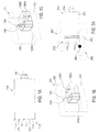
- FIG. 1A shows a first embodiment of a drill bit according to the invention 110 with a main crown part 111, a degrading region 112, a plurality degrading members 113 and a fixing member 114 and a plurality Semiconductor magnetic field sensors 112 as a sensor device according to the invention, the are arranged in the degrading region 112.
- the state of each Semiconductor magnetic field sensors 121 depends on the electromagnetic environment of Drill bit 110 from.
- About the attachment part 114 can be the drill bit 110th for example, couple with the drive shaft of a prime mover.
- the degrading elements 113 may be integral with the main crown part 111 executed, or be implemented as separate units by means of a corresponding fastening method or corresponding fixing elements solvable or non-releasably attached to the main crown portion 111.
- the semiconductor magnetic field sensors 121 for example, Hall elements, magnetoresistive sensors and giant magnetoresistive (GMR) Sensors are used.
- the semiconductor magnetic field sensors 121 each in one of the preferred direction of rotation of the drill bit 110th arranged opposite side of a respective degrading element 113, are thus during a degrading rotation of the drill bit 110 in preferred direction of rotation, so to speak "in the shadow" of the respective degrading Elements 113 and so are damaged during the drilling process protected.
- the semiconductor magnetic field sensors 121 in the degrading Area 112 of the drill bit 110 can in particular the electromagnetic Environment of the drill bit 110, which is in the immediate vicinity of the degrading Area 112 of the drill bit 110 is located, examined or evaluated.
- Figures 1B and 1C show respective schematic detail views of a possible Arrangement of a Hall sensor 121H with two permanent magnets 128S, 128N, for example, as semiconductor magnetic field sensors 121 in a drill bit according to Figure 1A could find application.
- the Hall sensor 121H and the two Permanent magnets 128S, 128N are in a plastic sheath, for example in a potting compound 130, or in a non-ferromagnetic metal in order Forming embedded.
- the two permanent magnets 128S, 128N are arranged so that their respective magnetic main axis perpendicular to a wear surface 131 provided side of the formed by the potting compound 130 Semiconductor magnetic field sensor 121 are aligned.
- the two permanent magnets 128 S, 128 N arranged so that their respective magnetic main axis are aligned parallel to the wear surface.
- FIG 2A shows a further embodiment of the invention, wherein a Drill bit 210 analogous to the drill bit 110 shown in Figure 1 a Main crown part 211, a fixing part 214 and a degrading area 212 having a plurality of degrading elements 213.
- the drill bit 210 is equipped with a coil 222, the acts as a sensor device according to the invention.
- the coil 222 is preferably connected to a detector circuit which in accordance with the known principle of a metal detector, the coil 222 excited and measures and evaluates their impedance changes.
- the drill bit 210 approaches a reinforcing rod 281, so the course and the strength changes through the energized coil 222 induces magnetic field 282, which in turn causes a change in the magnetic field Impedance of the coil 222 causes.
- the proximity of a Find reinforcing iron to drill bit 210 is preferably connected to a detector circuit which in accordance with the known principle of a metal detector, the coil 222 excited and measures and evaluates their impedance changes.
- the drill bit 210 approaches a reinforcing rod 281, so the course and the strength changes through the energized coil 222 induces magnetic field 282, which in turn causes a change in the magnetic field Impedance of the coil 222 causes.
- the proximity of a Find reinforcing iron to drill bit 210 is preferably connected to a detector circuit which in accordance with the known principle of
- Figures 2B and 2C show respective embodiments of an inductive element that may be used in a drill bit as a sensor device. Shown is a U-shaped yoke 224 having two yoke legs and a connecting yoke leg connecting piece.
- the yoke is made of a material of high permeability, in particular of a ferromagnetic metal, and has at its open end its U-shape an air gap which is narrower than the distance between the yoke legs.
- a coil 222 ' is wound around the yoke 224, preferably around the connector, to realize a high quality coil 222'.
- FIG. 2C dismantling elements 213 'are arranged next to the air gap at the respective yoke leg end.
- a high permeability article such as a reinforcing bar near the deoxidizing elements 213 'effectively causes an easily detectable, magnetic short circuit of the coil 222' via the yoke 224 extended by the depleting elements 213 '.
- Figure 2D shows an embodiment of a drill bit 210 'with a sensor device in the form of a yoke-coil combination formed according to the embodiment of Figure 2C.
- About the slip rings 243 can be a circuit between the at the rotating drill bit 210 'mounted coil 222' and a quasi-stationary Establish measuring device.
- FIG. 2E shows a modification of FIG Embodiment of Figure 2D, in which the slip rings 243 'of a Tool holder 274 a suitable for driving a drill bit Drive machine are included.
- An ohmic signal path between Winding ends of the coil 222 'and the respective slip rings 243' can over in or on the drill bit 210 'arranged lines 240 and over in or on the tool holder arranged lines 240 'are produced.
- a cost-effective separable ohmic connection of the lines 240 'of Tool holder with respective drill bit conduits 240 may, as shown, for example, via respective, with appropriate conductive and insulating Areas executed pins 246 on the attachment portion 214 'of the drill bit 210' take place, contact the respective contact surfaces 245 of the tool holder.
- pins 246 for transmitting power from the tool holder 274 to the drill bit contribute.
- FIG 3A shows a further embodiment of the invention, in which a Drill bit 310 analogous to the drill bit 110 shown in Figure 1 a Main crown part 311, a degrading area 312, several dismantling Having elements 313 and a fixing part 314.
- the drill bit 310 both with an excitation coil 322E and with several in the depleting region 312 of the bit 310 arranged sensor coils 322S equipped, the latter as act according to the invention sensor device.
- the excitation coil 322E induces Magnetic field, the shape and strength of the impedance of the sensor coils 322S which provides information about the electromagnetic environment of the drill bit 310 can deliver. Due to the illustrated arrangement of the sensor coils 322S in degrading region 312 of the drill bit 310 may in particular the electromagnetic environment of the drill bit 310, which is in close proximity of the degrading region 312 of the drill bit 310 is examined or be evaluated.
- FIG. 3B shows an exemplary embodiment of an inductive element that can be used as both Magnetic field exciter as well as a magnetic field sensor in the sense of a can act according to the invention sensor device.
- the inductive element shown comprises a U-shaped yoke 324, the two Yoke leg and a connecting piece connecting the yoke legs having.
- the yoke legs are each as a permanent magnet 328th made of different polarity, so that the yoke 324 is a uniform build up magnetic field.
- the yoke is made of a material of high permeability, in particular made of a ferromagnetic metal.
- the yoke legs however, sections of the yoke legs may be of a rare earth be manufactured, which has pronounced permanent magnetic properties.
- a sensor coil 322S ' is wrapped around the yoke 224, preferably around the yoke 224 Connector, wound.
- the yoke has its U-shape at the open end Air gap, which is narrower than the distance between the yoke legs, what together with the high permeability of the yoke material to a sensor coil 322S 'high quality leads.
- the pole pieces may themselves carry the cutting segments, i. the dismantling elements of the drill bit form, and would then preferably out appropriate materials such as Ni matrix or industrial diamonds to manufacture.
- the degrading elements 313 ' are preferably made of a material higher Permeability, in particular made of a ferromagnetic metal. On this meadow causes a high permeability object such as a Reinforcing bar near the deboning elements 313 'effectively a light detectable, magnetic short circuit of the sensor coil 322S 'via the yoke 324 extended by the degrading elements 313 '.
- the inductive element of Figure 3B can be analogous to the embodiments FIGS. 2D and 2E as part of a drill bit according to the invention.
- the rotation of the drill bit during drilling is in the yoke 324th formed magnetic circuit formed by the two permanent magnets 328th is biased, each time induces a voltage when the air gap of the Yoke on a ferromagnetic article, e.g. on a rebar, moved past.
- the reinforcing iron reduces the effective air gap of the magnetic circuit of the yoke, resulting in a flux change and thus after the Induction law leads to an induced voltage. Because the Cutting speed is always about the same, the induced voltage is over different Bohrkronendruchmesser comparable.
- FIG. 3C shows a further embodiment of an inventive device Drill bit 310 'with a wound around the axis of rotation of the drill bit 310' Exciting coil 322E 'and several parallel to the lateral surface of the Main crown part 311 'of the drill bit 310' wound sensor coils 322S ", which in or are arranged on the drill bit so that the excitation coil 322E 'and the Sensor coils 322S "are orthogonal to each other.
- the drill bit is preferably made of non-ferromagnetic and / or poorly conductive material, in particular from non-ferromagnetic steel, manufactured to eliminate eddy current effects curb preferred AC-based measurement method. To this still in addition to reducing the drill bit can be slotted at a suitable location become.
- the 322S "sensor coils can be used in conventional multi-layer circuit board technology on flexible, organic substrates (e.g., polyamide) be made so that they simply as a total band on the drill bit 310 ' can be glued on.
- the connection of the coils 322 to a measuring and Evaluation electronics can then also with a ribbon cable, the corresponding lines 340, and via a coupler or slip rings 343 be realized.
- a sense amplifier in the Bohrkrone be 310 'integrated for example by means of a serial Protocol communicates with a corresponding evaluation device, e.g. is housed in a prime mover.
- the drill bit 310 'shown in FIG. 3C is particularly suitable for measuring methods.
- the excitation coil 322E 'applied axially to the drill bit 310' generates an alternating magnetic field, for example in the kHz frequency range and the distortion of this field, for example, due to the proximity of a Arm michsseisens the coils 322 can be caused by means of parallel to the lateral surface of the drill bit applied sensor coils 322S "is detected.
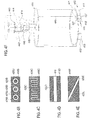
- Figure 4A shows details of a drilling system according to another Embodiment of the invention.
- the degrading element 413 for example, a conductive matrix 416 with Diamond grains, pass a plurality of electrically conductive regions 425, which through a respective electrically insulating region 426 of the electrically conductive Material of the element 13 are electrically isolated.
- An electrically conductive area 425 is via a first line 440 with a measuring and evaluation device 450th connected.
- the element 413 is via a second electrical line 440 'connected to the measuring and evaluation device 50.
- FIG. 4A shows by way of example only the connection of one of the electric conductive areas 425 with the measuring and evaluation 450 represents would be typically all electrically conductive areas 425 each individually or in groups in series or parallel connection with appropriate input or Output gates of the measuring and evaluation 450 connected.
- the measuring and evaluation device 450 By means of resistance measurement via the electrically conductive regions 425 and the electrically conductive element 413, the measuring and evaluation device 450, the preferably via a signal processing and a corresponding display provides information about the electromagnetic environment of the drill bit.
- FIGS 4B to 4E show various possible embodiments of a degrading element, in particular a degrading element for use in a drilling system analogous to the embodiment of Figure 4A. Shown is each a cross-section of a preferably annular and one-piece executed degrading element parallel to a degradation or abrasion level this element, which is typically perpendicular to the axis of rotation of the drill bit arises.
- this element which is typically perpendicular to the axis of rotation of the drill bit arises.
- the electrically conductive regions and / or the electrically conductive Elements also with a wear of the eroding area of the drill bit stay electrically isolated from each other.
- Figure 4B shows a degrading element of a drill bit according to another Embodiment of the invention, wherein the electrically conductive regions 425B Similar to the embodiment shown in Figure 4A circular cylindrical formed and of respective annular cylindrical electrically insulating Are surrounded areas 426B.
- the electrically conductive regions 425B and the electrically insulating regions 426B pass through an electrically conductive Matrix 416B as a primary degrading element.
- the cylindrical areas do not have to have the shape of a circular cylinder.
- Figure 4C shows a degrading element of a drill bit according to another Embodiment of the invention, wherein an electrically conductive region 425C and an electrically conductive matrix 416C as a primary degrading element an electrically insulating region 426C are isolated from each other.
- the electrically insulating region 426C has a shape that has the shape of a Rectangular signal is similar.
- Modifications of the The course of the electrically insulating region 426C are self-evident equally useful. For example, the course could be swung instead be formed rectangular or on the same side of the degrading element end or be designed ring-shaped.
- Figure 4D shows a degrading element of a drill bit according to another Embodiment of the invention, wherein an electrically conductive region 425D and an electrically conductive matrix 416D as a primary degrading element a strip-shaped electrically insulating region 426D isolated from each other are parallel to two sides of the degrading element.
- Figure 4E shows a degrading element of a drill bit according to another Embodiment of the invention, wherein an electrically conductive region 425E and an electrically conductive matrix 416E as a primary degrading element a strip-shaped electrically insulating region 426E isolated from each other are at an angle from one side of the degrading element to one opposite side of the degrading element runs.
- the angle with which the electrically insulating region 426E traverses the degrading element can, unless the mechanical stability of the degrading element thereby affected, are freely chosen.
- FIG. 4F shows an exemplary embodiment of a drill bit 410, which is provided with a plurality of is provided as ohmic contacts 427 running conductive areas. These are connected in parallel by means of a line 440.
- the ohmic contacts 427, which act as a sensor device according to the invention 420 are at a the degrading area 412 forming area of the drill bit 410 and arranged are surrounded by a degrading element 413 ', in its outer Shape of other destructive elements 413 of the drill bit 410 not to is different.
- the ohmic contacts 427 are via one or more lines arranged in or on the drill bit 410 540 connectable to a measuring device.
- the line 440 of the drill bit 410 contacts a corresponding line 440 ' and a slip ring 443 of a tool holder 474 of a not shown Drive machine by means of a fastening part 414 of the drill bit 410th arranged pin 446 and a corresponding, on the tool holder 474 provided contact surface 445th
- the conductive matrix 416 may also be the Assume role of a conductive region 425 and vice versa. A Distinction between conductive matrix 416 and conductive region 425 may be however, be seen in it, if the matrix has a greater role in the bearing Structure of the drill bit or the respective degrading element plays.
- Figure 5A shows a schematic representation of another embodiment of the The invention relates to a drill bit 510 with a sensor device 520 acting eddy current sensor element 523.
- Figure 5B shows a detail view the sensor device 520 also schematically.
- the example of a Eddy current sensor element 523, shown in FIG Ferrite core 529 and a coil wound around the core 522nd are in Plastic or metal encapsulated to the eddy current sensor element 523.
- the eddy current sensor element 523 is in a potting compound 530th made of plastic or embedded in a metal, so that the eddy current sensor element 523 can be used as a degrading element 513 '.
- the packaging of the eddy current sensor element 523 has the shape of a degrading element 513, i. the thickness and the radii of curvature of the embedded eddy current sensor element 523 are identical to the others degrading elements 513, i. Cutting elements, the drill bit.
- the illustrated eddy current sensor element 523 could, for example, for the Detection of rebar to be used on diamond core bits.
- the eddy current sensor element 523 preferably consists of an elongated Ferrite pot core and a Cu baked enamel wire winding with some 100 to some 1000 turns.
- the open side of the ferrite core shows a wear surface 531, i. to the cut surface of the degrading element 513 'and is flush with this.
- the coil length is shorter than the winding space of the ferrite pot core, i. the Coil will only be around a short section away from the wear surface
- the ferrite core 529 is wound by the wear of the ferrite core 529 the degrading area 512 of the drill bit, i. the diamond segments, also shorter. In this way, the air gap between eddy current sensor and reinforcing bars are kept constant over the life of the crown.
- the coil windings are the Coil 522 via arranged in or on the drill bit 510 lines 540 with a measuring device connectable.
- the lines 540 of the drill bit 510 corresponding lines 540 ' and slip rings 543 of a tool holder 574 of a not shown Drive machine by means of a fastening part 514 of the drill bit 510 arranged pin 546 and a corresponding, on the tool holder 574 provided contact surface 545th
- Coils, other inductive elements and conductive elements in particular the as described above, to use as signaling devices.
- the signaling devices may be separate from the sensor devices be executed or also have a bifunctionality, i. simultaneously or sequentially both as a signaling device and as a sensor device act.
- too Permanent magnets as well as electromagnets as a signal generator according to the invention Find use.
- the preference for the explicit naming of this Signaling devices should by no means be interpreted as limiting.
- other signaling devices such as electro-acoustic, capacitive, etc. signal generator within the scope of the invention makes sense be used.
- the signal is less in the case of non-contact sensors such as Hall sensors or coils than if the drill bit already touches the reinforcing rod.
- the signals are periodic with the rotation angle of the drill bit and have a pulse-like character.
- they are voltage pulses, in the case of a coil, it may be short frequency changes. These frequency changes can, however, also be converted into voltage pulses and detected in the same way as voltage pulses, for example by means of a counter. Therefore, in the following explanations, it is assumed that they are voltage pulses.
- a global measurement method is when not (locally) at a point at the front end of the crown, but distributed over the entire circumference of the crown is detected.
- Such a measurement method is, for example, that the entire drill bit acts as an eddy current sensor or as a metal detector.
- a preferably fine-layered coil can be wound around the drill bit at the front end of the crown. By appropriate excitation, this coil generates a high-frequency alternating field, which is changed by the presence of reinforcing iron. This causes an impedance change of the coil, which can be detected by means of an oscillator circuit.
- the drill bit is advantageously made in this case of non-ferromagnetic, high-resistance steel or even better non-conductive fiber composites. In the latter case, it is possible to perform the drill bit like a highly sensitive metal detector. With regard to an evaluation of the measurement signals, reference is again made to the relevant literature in the field of metal detectors.
- An inductive sensor is a preferred sensor device of the invention.
- a corresponding drill bit or a corresponding drilling system and a appropriate measuring and evaluation can be by means of implement the following features in a preferred manner.
- Coupler, transfer to the rotating drill bit Coupling transformer or capacitive transformer.
- Measuring electronics LRC resonant circuit with high-frequency (5-50kHz) constant current source.
- engine speed via a Hall sensor on the rotor of the device.
- Signal evaluation Evaluation of the measuring voltage synchronous to the motor speed: Representation of the measuring signal as a function of the drill bit angle and cumulation of the measuring signals, moving away of the DC background and noise, setting a threshold and display.
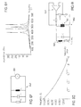
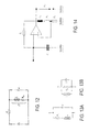
- FIG. 6A shows an exemplary realization of a drilling system 600 equipped with an inductive sensor and a corresponding evaluation device.
- a coil 622 which constitutes a sensor device according to the invention, comprised of a drill bit 610, is connected via a transformer transformer 641, which has a Signal transmission, for example, from the drill bit 610 to the engine or vice versa, excited by an oscillator 620 in resonance.
- This can be done for example by a simple RLC oscillator, which automatically resonates or by excitation of a resonant circuit with a constant frequency ⁇ 0, for example, with a square wave.
- the phase between current and voltage is regulated to zero.
- Characteristic of the realization of Figure 6A is that a capacitance C P is connected in parallel to the transformer inductance M and the sensor inductance Z s , so that a parallel resonant circuit via the transformer transformer 741 is formed.
- the detection of the (engine) speed and the determination of the Angle of rotation of the drill bit optional features of the invention.
- the current angle of rotation of the drill bit is preferably via a measurement of the Rotor speed and by a reference encoder on the spindle or the Drill bit determined.
- the engine speed is at today's drills Usually already detected for a speed control. What's added is one digital Hall sensor, i. a Hall switch, near the tool holder or spindle, the rotation angle of the spindle and thus the drill bit once recorded per assignment.
- This can be a simple notch or knob on the Be output shaft or at a suitable location in the transmission. In this case must used by a permanent magnet biased Hall sensor become. It is also possible, a permanent magnet to the output shaft to install. In this case, the Hall switch need not be biased.
- This complex variant is equal to an impedance measuring bridge.
- this variant has the basic function of an impedance bridge, but is in terms of accuracy, linearity and absolute measurement error not with one Laboratory instrument such as the well-known Precision Impedance Analyzer, Agilent 4294A, the company Agilent Technologies Co. Ltd. comparable.
- the measured values as such are not as important as the sensitivity of the measuring circuit.
- the measuring circuit is therefore preferably trimmed for high sensitivity.
- the available measuring signals can be both a change the impedance as well as a change in the resonant frequency, the in each case conclusion on the presence of a reinforcing iron or a allow other ferromagnetic article.
- the impedance of the entire Resonant circuit i. the sensor device with the transformer, purely ohmic. Of the Imaginary part falls away. If the resonant circuit with a constant Current amplitude operated, can via a measurement of the voltage amplitude over the coupling transformer readily to the impedance closed become.
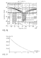
- the following table presents the advantages and disadvantages of some impedance measurement techniques applicable to the measurement of the impedance of a sensor coil located in a drill bit that changes, for example, by approaching an iron. Further details of the impedance measurement methods presented can be found in "The Impedance Measurement Handbook: A Guide to Measurement Technologies and Techniques", which is available from Agilent Technologies Co. Ltd. for example, at http://cp.literature.agilent.com/litweb/pdf/5950-3000.pdf. method advantages disadvantage applicable frequency range bridge methods High accuracy (0.1% typ.). Wide frequency coverage by using different types of bridges. Low cost. Must be calibrated manually. Narrow frequency coverage with one instrument. DC up to 300 MHz resonance method Good quality accuracy up to high quality values.
- the proximity of a ferromagnetic object can also be determined by the change the resonant frequency of the sensor device and the transformer determine the existing overall system. Because a linear dependence between the measuring or evaluation signal and the distance between iron and coil not is necessary if primarily the earliest possible detection of a reinforcing iron is set to the goal, the resonance frequency is a meaningful and sensitive measured variable
- f / V "frequency to voltage", i.e. frequency-to-voltage converter
- a Lowering the resonance frequency indicates a reinforcing iron.
- the signal value which is finally evaluated, is the difference of the resonance frequency without coupling by a reinforcing iron (offset, initial frequency) and the resonance frequency in the presence of a reinforcing iron.
- S k ⁇ [ f res ( L S0 ) - f res ( L S ( x ))]
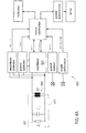
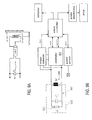
- the block diagram depicted in FIG. 7A shows an exemplary realization of a drilling system 700 equipped with an inductive sensor and a corresponding evaluation device.
- a coil 722 which represents a sensor device according to the invention encompassed by a drill bit 710
- a transformer transformer 741 which allows signal transmission, for example from the drill bit 710 to the prime mover or vice versa, excited by an oscillator 720 in resonance.
- This can be done for example by a simple RLC oscillator, which automatically resonates or by excitation of a resonant circuit with a constant frequency ⁇ 0, for example, with a square wave.
- the phase between current and voltage is regulated to zero.
- Figure 7A While the block diagram of Figure 7A represents a complex variant, the even allows an angle-faithful evaluation of the measured signals, Figure 7B shows a simplified variant, in the example only the amplitude and the Frequency of the oscillator signal and the engine or drive speed detected become. Also in the embodiment of Figure 7B is a series resonant circuit 752 via the transformer transformer 741 formed.
- FIG. 8A shows an exemplary embodiment analogous to FIGS. 6A, 7A and 7B Invention in which, however, the signal path between the sensor as a device acting sensor coil 822 and a measuring and evaluation circuit via a capacitive transformer 842 runs.
- a capacitive transformer 842 allows a signal transmission between a prime mover and a relative to Drive machine rotating drill bit.
- the capacitive can be Coupling element in the tool holder in the form of a cylindrical capacitor as radial embodiment or plate capacitor as axial Accommodate embodiment.
- Cooling water as a material with a high dielectric constant as Dielectric be used between the plates.
- Eddy current sensors are a standard tool for NDT (non-destructive testing: non-destructive testing) of electrically conductive, in particular metallic structures. Thus, e.g. in aircraft construction the carrying elements examined for cracks. An eddy current sensor reacts both on the permeability as well as on the inductance of the target. More about For example, eddy current measurement can be found in Scott D. Welsby and Tim Hitz. Nov. 1997, "True Position Measurement with Eddy Current Technology," Sensors, Vol. 14, no. 11: 30-40 can be found.
- Figure 9A shows a general arrangement for eddy current measurement.
- An eddy current sensor provides a preferred sensor device of the invention a corresponding drill bit or a corresponding drilling system and a corresponding measuring and evaluation device can be by means of implement the following features in a preferred manner.
- Coupler transfer to the rotating drill bit: Coupling transformer.
- Measuring electronics LRC resonant circuit with high-frequency (5-50kHz) constant current source.
- engine speed via a Hall sensor on the rotor of the device.
- Signal evaluation Evaluation of the measuring voltage synchronous to the motor speed: Representation of the measuring signal as a function of the drill bit angle and cumulation of the measuring signals, moving away of the DC background and noise, setting a threshold and display.
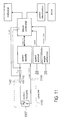
- FIG. 9B shows a possible realization a drill bit 910 according to the invention with eddy current sensor as Sensor device in the context of a drilling system with a corresponding measuring and evaluation device.
- the main component of the eddy current sensor forms a sensor coil 922, the mainly inductive impedance Z S, for example, together with the also mainly inductive impedance M of a transformer transformer 941 and a capacitor Cp LRC resonant circuit 952 forms.
- the measuring device includes a conventional oscillator 920, the LRC resonant circuit 952 with a given frequency f 0 and stimulates a constant current amplitude I 0th
- the oscillation frequency is either determined by the resonant frequency of the LRC resonant circuit 952, or is specified as forced oscillation by the microcontroller. For example, via a rectifier with a downstream low-pass filter, the voltage amplitude of the resulting oscillation of the LRC resonant circuit 952 is measured.
- the impedance is then calculated in a microcontroller functioning as an evaluation device: Z ( x ) U I 0 ⁇ Z 2 0 a ⁇ ( x + b )
- a simple and inexpensive oscillator circuit for such a driver circuit is an LC logic gate oscillator using CMOS logic gates. This can, as shown, be realized on the basis of two inverters.
- the two inverters produce a strong positive voltage gain. Therefore, the circuit oscillates at a frequency at which the phase shift of the resonant sensor is just disappearing.
- the output voltage is a rectangular voltage whose frequency is a function of the distance x between the coil and the reinforcing iron.
- this output voltage can For the purpose of evaluating this measurement signal, i. this output voltage, can For example, a microcontroller as an evaluation the frequency of Output voltage via a counter input, a so-called counter input, digitize, which counts the output pulses per unit of time.
- f ( x ) 1 2 ⁇ L ( x ) ⁇ ( C cable + C IWC + C p )
- V pp is the amplitude of the fundamental harmonics of the square wave signal at the output. It suffices to consider only this first harmonic since R S and the LC circuit form a bandpass filter around the oscillation frequency. This filter attenuates all components except the fundamental component. It makes sense to select the peak-to-peak amplitude Vpp at least as large as half the supply voltage V DD when the coil is unloaded, ie, when no reinforcing iron is in the vicinity. This rule implies that R S ⁇ R res , where R res is determined in the unloaded state, ie without any reinforcing iron in the vicinity. The higher the resistance at resonance, the less power is required for the operation of the sensor. The resistance increases with increasing frequency, increasing inductance and higher Q quality.
- the frequency response of an eddy current sensor depends on both the conductivity as well as the permeability of the environment it sensor, in particular one to detecting targets.
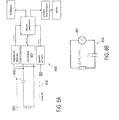
- An alternative measuring and evaluation circuit provide the proximity switches of OM series from Philips.
- FIG. 9E shows, as an example of this type series, the proximity switch OM 286 oscillator operating at T1, D1 oscillates at a frequency determined by C1 and the coil N1, N2 is given. If the coil, for example, by approach damped by a reinforcing iron, the vibrations break off, the working point T1 shifts, and the Schmitt trigger consisting of T2, T3 switches. Over the power stage (T4), then, e.g. a relay switched or an LED operated. About the resistance R, the sensitivity of the Adjust proximity sensor.
- a two-wire Hall sensor provides a preferred sensor device of the Invention.
- a corresponding drill bit or a corresponding Drilling system and a corresponding measuring and evaluation can be realize by means of the following features in a preferred manner.
- Coupler, transfer to the rotating drill bit slip ring, earth potential.
- a shunt resistor is used to measure the current consumption of the Hall element, followed by a low-pass filter, amplifier and A / D converter, microprocessor.
- Measuring signal (s) Hall voltage.
- engine speed via a Hall sensor on the rotor of the device.
- Signal evaluation Evaluation of the measuring voltage synchronous to the motor speed: Representation of the measuring signal as a function of the Bohrkronenwinkels and cumulation of the measured signals, moving away of the DC background and noise, setting a threshold and display.
- Two-wire Hall sensors provide a measurement signal in the form of power consumption. They use an internal power source, depending on the strength of the magnetic field is changed. About a series resistor, the current and thus the Magnetic field can be measured as a voltage. In other words, one changes integrated Hall sensor circuit, their current consumption, i. their DC resistance over the source. Does the magnetic flux density change near the sensor, so also changes its power consumption. This can, for example, with a Series resistance can be measured.
- FIG. 10 shows an exemplary realization of a device according to the invention Drill bit 1010 with a sensor device 1020 based on a two-wire Hall sensor 1021H, wherein the drill bit 1010 part of a with a corresponding evaluation device equipped drilling system 1000 forms.
- the sensor device 1020 also includes a permanent magnet 1028, referred to as Magnetic field source for the Hall sensor 1021H acts.
- a slip ring 1043 ago As a sensible way of signal transmission between the 1010 with the drill bit rotating sensor device 1020 and the example in a Drive machine arranged measuring device, sees the embodiment the use of a slip ring 1043 ago. This can be done on the upper shaft of the Drill bit 1010 an isolated collector, i. a slip ring 1043 mounted Be isolated with the positive potential of the Hall sensor 1021H connected is. The earth potential 1144 for the supply of the Hall sensor 1021H is guided over the device ground and over the drill bit 1010 itself. This saves a slip ring.
- the slip ring 1043 is for example by means of brushes tapped in the tool holder of the drive machine.
- a coupling transformer together with a rectifier on the secondary side i. on the at the Drill bit mounted side of the transformer, find use.
- the rectifier supplies power to the Hall sensor.
- the current consumption of the Hall sensor hangs from the magnetic flux density. The current consumption can over the Power consumption (or over the current) on the primary side of the Be measured transformer.
- Ohmic contact elements provide a preferred sensor device of Invention.
- a corresponding drill bit or a corresponding Drilling system and a corresponding measuring and evaluation can be realize by means of the following features in a preferred manner.
- Coupler, transfer to the rotating drill bit slip ring, earth potential.
- a shunt resistor measures the current consumption, followed by a low-pass filter, amplifier and A / D converter, microprocessor.
- Measurement signal (s) Resistance change at the drill segments.
- Signal evaluation Evaluation of the measuring voltage synchronous to the motor speed: Representation of the measuring signal as a function of the drill bit angle and cumulation of the measuring signals, moving away of the DC background and noise, setting a threshold and display.
- FIG. 11 shows an exemplary realization of a device according to the invention Drill bit 1110 with a sensor device based on ohmic Contact elements 1127.
- Such contact elements 1127 can, for example by conducting in a degrading matrix 416 of the drill bit 1110, conductive Elements 425 are realized, as shown in Figures 4A to 4F.
- ohmic contact elements provides a simple and robust Possibility for the iron detection dar.
- a disadvantage of the method is that a Detection of iron can only be done during drilling. If you do not want the iron For example, an inductive (coil), magnetic (Hall) or eddy current method are used.
- FIG. 11 shows an embodiment in which a Signal transmission between the rotating with the drill bit 1010 Sensor device and one example in a prime mover arranged measuring device via a slip ring 1143 takes place. protection elements against overvoltage when drilling to a live cable are not drawn.
- a circuit of the measuring and evaluation device for example in the Drive machine to the ohmic contact elements in the drill bit can via two slip rings, each having a signal path to or from the Allow drill bit.
- the circuit can, as shown, on the ground potential of the Underground 1144 closed.
- a coupling transformer instead of the slip ring 1143, a coupling transformer be used.
- the transformer will vary depending on the resistance of the Contact elements loaded or even short-circuited on the secondary side. This change in resistance can be due to the power consumption on the Primary side are measured.
- Any local measurement method i. any local probe at one point of the attached to the front end of the drill bit, generates a rotation angle of the Drill bit periodic, pulse-like signal. Whether it is a Hall sensor or is an inductive proximity sensor, actually plays no Role. In the first case, voltage pulses are actually generated, in the second case it is rather pulse-like frequency changes that have to be detected. in the Case of ohmic contact, i. a switch, it is Resistance changes, which in turn, for example, as a voltage change can be detected.
- FIGs. 15A-15D a simulation becomes five different situations discussed. It is assumed that a Reinforcing iron at five different places relative to the center of a Drill bit is drilled.
- Figure 15A shows this simulation assumption. shown is the outline of a drill bit 1510 and five reinforcing bars 1581A-1581E. The intersections of a respective Arm michseisens 1581 through the drill bit 1510 are marked by dots.
- Figure 15B shows the simulated, normalized resistance change of a ohmic contacts obtained measurement signal as a function of the rotation angle of the Drill bit 1510 in rad.
- the illustrated Meßsignalverrise correspond from top to bottom by detecting the respective reinforcing iron 1581A to 1581E expected Me ⁇ signalverlauf.
- the lowest curve thus corresponds a detection of armouring 1581E.
- the in Meßsignalverlauf occurring pulses are wide and relatively close together. The closer that Reinforcing iron is moved towards the center of the drill bit, the more The pulse distribution becomes more symmetrical, and the pulses become shorter.
- FIG. 15C illustrates an analogous situation in which no resistance values, but (normalized) voltage values of a (digital, i.e. analogue Hall sensor with Schmitt trigger) Hall sensors can be simulated.
- the pulses are comparable, only the sign is reversed.
- FIG. 15D shows a schematic illustration the simulated frequency change of, for example, in a degrading Element of the drill bit 1510 arranged, inductive proximity sensor.
- the frequency was chosen very low, which does not correspond to reality.
- the frequency digitized directly via a counter input of a microcontroller and thus be translated into a numeric value.
- f / V converter For an analog pulse detection offers a frequency-voltage converter (f / V converter).
- a pulse detection is preferably done in a microcontroller. As soon as a peak is detected, ie as soon as the voltage at the input of an A / D converter of the microcontroller has exceeded a certain threshold U thr , and the length of the pulse does not correspond to drill bit longer than a quarter turn, the pulse is considered detected. For safety, a second pulse can be waited for, which also fulfills these conditions. Only then does the reinforcing iron apply as detected.
- a target has been detected, this circumstance can be displayed to the user and / or appropriate actions can be initiated (e.g., engine switch off, stop feed motor).
- a robust and preferred evaluation method for all local measuring methods is based on a synchronous measurement of the angle of rotation of the drill bit. Become the measuring signals (whether it is an impedance change, a change of Resonant frequency or a change in resistance) as a function of Rotation angle modulo 2 ⁇ represented, so will always be at the angle where For example, an iron is detected, signals accumulate. Will the Angular range in e.g. ten sectors are classified as 36 ° (sector classes) and the summed mean signal amplitudes within a respective sector, so are in areas where a reinforcing iron is actually, the Cumulate signals while the noise in the remaining areas is averaged out. An underground caused by the "DC offset" said DC offset can be easily determined and subtracted become. The signals accumulated in the sectors exceed a certain amount Threshold, this is displayed, for example, or the drive is stopped.
- the accumulated classes are reset to zero.
- the reset can also be triggered manually by the user.
- a Alternative is that the accumulated signals within the classes by means of a Very slow high-pass filter (cutoff frequency, for example, 15-30 sec) entrained become.
- cutoff frequency for example, 15-30 sec
- an indicator in the form of a ring of LED around the tool holder.
- the LEDs can be activated according to the amount of detection. This not only indicates to the user that a rebar has been encountered or will soon be encountered, but also where the rebar (approximately) is located.
- the coil is not locally in place of a grinding element of Drill bit is attached, but for example axially around the drill bit is wound, is similar to a metal detector.
- the coil is as far as possible at the front end of the drill bit, just behind the drill bit Abrasive elements.
- the lateral surface of the drill bit made of non-metallic material. Provide fiber reinforced composites Here is a preferred solution.
- the diamond segments at the end of Drill bit still attached to a metallic ring.
- the signal evaluation consists in this case of the determination of a certain Minimum threshold which the output signal of the metal detector must reach so that a reinforcing iron has been detected with certainty.
- Metal detectors can also be realized with oscillator circuits, which with a quality or frequency change to the presence of iron react. (see the section "Eddy current sensors”)
- the evaluation of a directly from the sensor device or indirectly via a preceding measuring device supplied measuring signal in a measuring device or in a specially provided for this purpose Evaluation device done.
- the evaluation can be done solely on the basis of the o.g. Measuring signal or in conjunction with other parameters, in particular in Related to further drilling parameters such as cutting speed, Pressing force, water supply, torque, etc., take place.
- the Evaluation as a function of predetermined, measured and / or of a Users of a drilling system according to the invention supplied parameters.
- the evaluation result and / or one or more of the other parameters can be returned to the measuring device and / or the sensor device Become a better, especially a user's requirements adapted to achieve evaluation result.
- the user might determine via an appropriate input device, if rather a high Detection sensitivity in which a target is detected early, i. also from big Distance, is detected, or rather a high detection accuracy, in which little "false messages" occur, is desired.
- the cutting speed as a parameter to choose between Detection accuracy and detection sensitivity are used, wherein when drilled quickly through the drilling surface, rather the sensitivity the detection is emphasized, but when slowly drilled through the underground is, greater value may be placed on the detection accuracy.
- a greater detection sensitivity could be achieved, for example be arranged that several in the degrading area of the drill bit Sensor devices are switched on, while, for example, a larger Detection angle accuracy could be achieved that only one in a limited extent of the drill bit detecting sensor device is switched on.
- the measuring and evaluation device can be both analog and digital Components include. Also they can be in the form of a programmable Hardware be executed, whose operation via an appropriate Program software is determined.
- the drilling system comprises a signaling device incorporated in Depending on the measurement and / or evaluation signal an adjustment of or automatically performs a plurality of Bohrparameters, and / or a user a Adjustment of one or more drill parameters perceptibly signaled and / or a user perceive an exchange of the drill bit signals, and / or a user the detection of a target perceptible, in particular visually and angled, signaled, and / or the drilling process automatically stops.
- the adaptation comprises one or more Bohrparameters an adjustment of the torque, the cutting speed, the water supply, the contact pressure and / or the drilling power.
- FIG. 16 shows a schematic illustration of a signaling device 1660 a drilling system according to the invention 1660 according to another Embodiment.
- the illustrated signaling device 1660 comprises a microcontroller 1653 and a display device connected thereto 1661.
- the microcontroller 1653 is also equipped with 1671 power electronics connected via the microcontroller 1653 a drive the drill bit serving drive device 1673 and the feed of the drill bit Serving feed device 1672 can regulate.
- the display device 1661 is designed in the form of a ring whose outer perimeter LEDs are mounted at regular intervals.
- the Ring has, for example, a contacting and fastening element which a signal transmission between the display device 1661 and the Microcontroller 1653 via a corresponding contact element on the housing of Drive machine allows, and the ring in a unique position in the Attached ratio to the prime mover.
- the Display device attachable to the tool holder.
- a drill bit according to the invention as well as a drilling system according to the invention may include one or more sensor devices and / or Signalgebervorrichept exhibit. These are preferably to be aligned in a manner that a optimal target detection, preferably optimal detection sensitivity, or other preferred evaluation result in a preferred Detection direction, preferably in the drilling direction guaranteed.
- the sensor devices and / or Signalgebervorrichungen rotationally symmetric or rotationally asymmetric to Rotation axis of the drill bit in or on the drill bit or in or on one Drive machine can be arranged.
- sensor devices and / or Signalgebervorrichiers are mechanically and / or electrically too to ensure a long service life of these devices.
- This protection can be realized that the sensor devices and / or Signalgebervorrichonne in one of the mechanical and electrical Load corresponding potting compound, a corresponding metal or in corresponding recesses of the drill bit are encapsulated.
- the sensor devices and / or Signalgebervorrichache and a Measuring and evaluation device extending signal lines preferably protect.
- Embodiments of a suitable rotary Signal transmission connection for example, in connection with the Embodiments of Figures 2E, 8A, 4F and 5A described in detail, why at this point to a repetition of the local statements is waived.
- the principle that will suggest here uses the effect of detuning a (not necessarily resonant) resonant circuit by a change in the Sensor coil impedance.
- Figure 6B shows a coupling of an oscillator 620 to a parallel resonant circuit 652 by means of a transformer in the form of a coupling transformer 641 in a schematic representation.
- the resonant circuit 652 is formed, for example, from the sensor coil 622, a capacitance C P and the inductance M of the coupling transformer 641, ie the transformer inductance M.
- the impedance Z S of the sensor coil 622 includes both an inductive 622L (L s ) and a real 622R (R s ) portion; the capacitance C P is connected in parallel to the transformer inductance M.
- the resonant frequency of the system is greatly different from the Sensor inductance depends.
- the resonant frequency depends quite linearly on the Sensor inductance from.
- the resonant frequency f res falls from 53 kHz to 40 kHz using the same values as above according to the function shown in FIG. 6G. This shows that the resonant circuit is not dominated by the transformer inductance, but is quite sensitive to a small change in the sensor inductance L S.
- FIG. 6H shows the behavior of the impedance according to the above equation for different sensor inductance values.
- the impedance can also be calculated directly without having to calculate equivalent parallel inductances and shunt resistances.
- FIG. 6I shows how a drill bit 610 with a sensor element 622 ( Z S ) can be coupled to an LC oscillator 620, which is preferably formed in or on a drive machine for the drill bit, not shown, via a coupling transformer 641.
- the parallel capacitance C P of a parallel resonant circuit 652 can be arranged on the drill bit itself.
- FIG. 6J The reduced equivalent circuit diagram shown in FIG. 6J shows that it is in fact a conventional parallel resonant circuit 652 with the components L PP and C P.
- a series resonant circuit with transformer transformer can be to Signal measurement and transmission in a drilling system according to the invention make sense.
- This is a capacity on the drill bit opposite side of the transformatory transformer in series with the Connected transformer.
- the capacity for example, part of a Drive machine, which in the drilling system for driving the drill bit Use, or even part of a corresponding measuring and / or Form evaluation circuit.
- FIG. 7C shows a series resonant circuit 752 with transformer transformer in which the T-equivalent circuit diagram 741 'of the transformatory transformer used analogously to Figure 6C instead of the transformer transformer has been.
- L PP L S ⁇ M L S + M
- ⁇ res L S + L ⁇ + M C ⁇ ( L 2 ⁇ + L S ⁇ L ⁇ + 2M ⁇ L ⁇ + L S ⁇ M )
- the resonant frequency f res falls from about 35 kHz to 30.5 kHz using the same values as above according to the function shown in FIG. 6G. This shows that the resonant circuit is not dominated by the transformer inductance, but is quite sensitive to a small change in the sensor inductance L S.
- a high-frequency alternating current In the sensor coil By applying a high-frequency alternating current In the sensor coil, eddy currents form in the reinforcing iron.
- This second rung in the rebar can be like the secondary coil of a Transformers are treated, the low on the mutual inductance Primary coil couples.
- the system sensor coil armouring iron can in a equivalent equivalent circuit to be converted whose impedance from the Mutual inductance M (x) between sensor coil and conductive surface of the Reinforcing iron and thus strongly from the distance x between the sensor coil and Iron surface depends.
- FIG. 9C shows the general course of the inductance and the equivalent loss resistance as a function of the distance. From this it can be seen that the loss resistance R eq is almost hyperbolic for larger distances, while it saturates for small values at a certain maximum value. This is because for small distances x no longer the entire flux penetrates the sensor coil. While the change in the equivalent resistance is almost one order of magnitude, the inductance change is only 5-10%. R eq ( x ) ⁇ a x + b
- a first option is to use a constant-frequency LC oscillator Amplitude response. Damp eddy current losses due to the proximity of the iron this oscillator, and the amplitude of the oscillation decreases. Disadvantageous In this approach, nonlinearities of the oscillator (e.g., as a function of the Temperature) itself affect the amplitude response, and that the Amplitude change is not a linear function of the distance x.
- ⁇ Z Z ( ⁇ R S / R S ) 2 1+ Q 2 + ( .delta..sub.L / L ) 2 1 + 1 / Q 2
- This phase angle can be achieved by means of a phase-sensitive rectifier be detected and compensated.
- FIG. 13A shows a series resonant circuit
- FIG. 13B shows a parallel resonant circuit.
- the resistance represents the Losses of the coil.
- Inductive sensors in resonant circuits typically consist of a single coil. For this reason, the distance characteristic (the inductance L as a function of the distance of the reinforcing iron) is also not linear. But since the resonance frequency is proportional to 1 / ( LC ) 1 ⁇ 2 , the frequency-spacing characteristic shows a more linear behavior.
- a preferred as the invention measuring circuit component oscillator the relatively stable PIERCE oscillator, as used for example in "Systemtechnik inductive displacement and force transducer. Receivers and connecting devices ", by Horst R Loos, publication date: 1992, ISBN: 3816905412 is described. He can from a transistor circuit with a grounded base and a capacitive Coupling between the emitter and the collector can be realized.
- a so-called Colpitts oscillator is particularly suitable for use as Inventive Meßscenskomponente suitable. Regarding the execution such an oscillator is based on the relevant literature on oscillators directed.
- the real part does not change; only the inductance decreases.
Abstract
Description
Die Erfindung betrifft ein Verfahren zur Bestimmung des elektromagnetischen Umfeldes einer Bohrkrone, insbesondere zur Detektierung von Armierungen, sowie ein entsprechendes Bohrsystem und eine Bohrkrone bei deren Einsatz sich Armierungseisen unter Anwendung des Verfahrens rasch detektieren lassen.The invention relates to a method for determining the electromagnetic Environment of a drill bit, in particular for the detection of reinforcements, and a corresponding drilling system and a drill bit when they are used Quickly detect reinforcing iron using the procedure.
Beim Bohren mit Diamantkronen auf armierten Beton kommt es oft vor, daß die Bewehrung (Armierungseisen) angebohrt wird. Dies kann die Sicherheit von besonders stark belasteten Elementen beeinträchtigen, da die Struktur geschwächt wird. Außerdem ist es vorteilhaft für den Anwender, zu wissen, wodurch er gerade bohrt. Aus dem Bohrfortschritt allein kann er nicht feststellen, ob er auf ein Armierungseisen gestoßen ist oder nicht, denn eine Reduktion der Abbaugeschwindigkeit kann durch vielerlei Faktoren wie eine stumpfe Krone, ein Armierungseisen oder eine Änderung der Härte, der Zusammensetzung, etc. des Gefüges verursacht werden.When drilling with diamond crowns on reinforced concrete, it often happens that the Reinforcement (reinforcing iron) is drilled. This can be the safety of particularly heavily loaded elements, as the structure is weakened. It is also beneficial for the user to know causing him to drill. He can not tell from the drilling progress alone whether he came across a rebar or not, because a reduction of Degradation speed can be affected by many factors such as a blunt crown Reinforcing iron or a change in the hardness, composition, etc. of Microstructure caused.
Wüßte der Anwender genau, welches die Ursache einer Reduktion des Bohrfortschrittes ist, so könnte er geeignete Gegenmaßnahmen treffen. Bei einer stumpfen Krone würde er die Krone ersetzen. Bei einer Änderung des Gefüges könnte er die Bohrparameter wie Drehmoment, Schnittgeschwindigkeit, Wasserzufuhr, Anpreßkraft, Bohrleistung, etc. entsprechend anpassen und/oder die Bohrkrone durch eine zum Bohren des vorliegenden Gefüges besser geeigneten Bohrkrone ersetzen. Nähert er oder stößt er auf ein Armierungseisen könnte er den Bohrvorgang abbrechen. Ist ein Durch- oder Anbohren einer Bewehrung beispielsweise aus Sicherheitsgründen unzulässig, so müßte er den Bohrprozeß abbrechen. Anderenfalls könnte er die Bohrparameter oder die Bohrkrone, wie oben beschrieben, anpassen bzw. austauschen, um ein schnelles Durchbohren der Bewehrung zu gewährleisten oder um die Bohrkrone zu schonen.Would the user know exactly what the cause of a reduction of As drilling progress is, he could take appropriate countermeasures. At a blunt crown he would replace the crown. At a change of the structure could he use the drilling parameters like torque, cutting speed, Adjust water supply, contact pressure, drilling capacity, etc. accordingly and / or the drill bit by a suitable for drilling the present structure more suitable Replace drill bit. If he approaches or encounters a rebar he could stop the drilling process. Is a piercing or drilling a reinforcement For example, for safety reasons inadmissible, he would have the drilling process abort. Otherwise it could be the drilling parameters or the drill bit, like described above, adapt or exchange to a quick puncture To ensure the reinforcement or to protect the drill bit.
Aus der DE 33 24 615 A1 ist ein Bohrsystem bekannt, bei dem ein Metallsuchgerät und/oder ein Spannungsprüfer an einem Ausleger befestigt sind, der seinerseits an eine Bohrmaschine in Richtung des Bohrlochs ausrichtbar fixiert werden kann. Zweck des Metallsuchgerätes ist es, ein Anbohren von Wasserrohren oder stromführenden Leitung zu vermeiden, indem die Stelle, an der gebohrt werden soll, mit Hilfe des Metallsuchgerätes zuerst geprüft wird. Der Spannungsprüfer ermöglicht es einem Benutzer, festzustellen, ob Leitungen an der Bohrstelle unter Spannung stehen.From DE 33 24 615 A1 discloses a drilling system is known in which a Metal detector and / or a voltage tester are attached to a boom, which in turn can be aligned with a drill in the direction of the borehole can be fixed. The purpose of the metal detector is to drill into To avoid water pipes or live line by the body, at which is to be drilled, is first checked by means of the metal detector. Of the Voltage tester allows a user to determine if wires are on the drilling site are under tension.
Dieses bekannte Bohrsystem erlaubt jedoch keine Bestimmung des elektromagnetischen Umfeldes einer Bohrkrone, die sich in einem Bohrloch befindet.However, this known drilling system does not allow determination of the electromagnetic environment of a drill bit, resulting in a borehole located.
DE 40 27 020 C2 lehrt ein Verfahren und beschreibt eine Vorrichtung zur Feststellung des Vorhandenseins von metallischen Bewehrungselementen im Inneren eines Betonbauteils. Dabei ist eine längliche elektromagnetische Sonde vorgesehen, die in ein vorher gebohrtes Loch eingeführt werden kann, um Auskunft über die Tiefe von etwaigen Bewehrungselementen zu liefern. Auf diese Weise ist es möglich, Hinterschnittbohrungen in ausreichendem Abstand von etwaigen Bewehrungselementen auszuführen. Nachteilig ist, daß Löcher auf herkömmlicher Weise vorgebohrt werden müssen, und daß Messungen im Inneren des Bohrteils somit erst nach dem Bohren ausgeführt werden können.DE 40 27 020 C2 teaches a method and describes a device for Determination of the presence of metallic reinforcement elements in the Interior of a concrete component. It is an elongated electromagnetic probe provided, which can be inserted into a previously drilled hole to To provide information on the depth of any reinforcement elements. To this Way, it is possible to undercut holes at a sufficient distance from any reinforcing elements. The disadvantage is that holes on conventionally must be pre-drilled, and that measurements inside of the drilling part can thus be carried out only after drilling.
DE 39 16 856 A1 offenbart eine Vorrichtung zum Auffinden und zum Schutz gegen das Anbohren von in Beton oder dergleichen verlegten Metallteilen, bei der ein Schwachstromkreis geschlossen wird, wenn die Bohrspritze auf eine Spannhülse, einen Spanndraht oder dergleichen trifft. Wird der Stromkreis geschlossen, so kann das Bohrgerät über Schaltkontakte in dessen Stromversorgung automatisch stillgesetzt werden. Es wird dabei angenommen, daß die verlegten Metallteile mindestens teilweise zugänglich sind und an einem Pol des Stromkreises angeschlossen werden können. Diese Vorrichtung bietet somit keine Möglichkeit, beispielsweise Bewehrungen, die vollständig im Beton eingebettet sind, zu detektieren und Eisentreffer zu verhindern.DE 39 16 856 A1 discloses a device for finding and protecting against the drilling of laid in concrete or the like metal parts, in the a low power circuit is closed when the drill syringe on a Clamping sleeve, a tension wire or the like hits. Will the circuit closed, so the drill via switch contacts in the Power automatically shut down. It is assumed that the laid metal parts are at least partially accessible and on a Pole of the circuit can be connected. This device offers thus no possibility, for example, reinforcements that are completely in the concrete are embedded, detect and prevent iron hits.
DE 101 29 597 C1 beschreibt ein Werkzeug für Werkzeugmaschinen, bei dem die Form und/oder die Abmessung von Markierungen im Schneidbelag ein Kennzeichen für den Grad von Verschleiß bildet. Dadurch kann ein Verschleißgrad mit einem Sensor erfaßt und in einer Steuereinheit zu einem Signal verarbeitet werden, beispielsweise zu einem optischen, akustischen und/oder elektrischen Signal, über das eine das Werkzeug antreibende Maschine abgestellt werden kann. Hierdurch wird lediglich das Werkzeug, nicht jedoch das zu bearbeitende Stück geschützt bzw. überwacht.DE 101 29 597 C1 describes a tool for machine tools, in which the Shape and / or the dimension of marks in the cutting surface Indicates the degree of wear. This can be a Wear level detected with a sensor and in a control unit to a Signal are processed, for example, an optical, acoustic and / or electrical signal through which a tool driving the tool can be turned off. As a result, only the tool, but not the Protected or monitored piece to be processed.
DE 196 34 533 A1 beschreibt ein Verfahren und eine Vorrichtung zur Bestimmung von physikalischen und chemischen Parametern in mineralischen festen Medien, bei dem bzw. der eine Meßlösung während des Bohrens durch das Bohrloch gespült und anschließend untersucht wird. Die Meßlösung kann mittels elektrochemischen Sensoren für Durchflußanalysen untersucht werden, die beispielsweise in den die Meßlösung führenden Schlauchleitungen am Ausgang eines Bohrfußes angebracht sein können. Der beschriebene Aufbau ist komplex und erlaubt eine Untersuchung von lediglich einigen wenigen Bohrlöchern pro Stunde, insbesondere wenn physikalische und chemische Parameter des Mediums auch in Abhängigkeit von der Bohrtiefe bestimmt werden sollen.DE 196 34 533 A1 describes a method and a device for Determination of physical and chemical parameters in mineral solid media, in which or a measuring solution while drilling through the Drilled hole and then examined. The measuring solution can by means of electrochemical sensors are investigated for flow analysis, the For example, in the measuring solution leading hose lines at the output a Bohrfußes can be attached. The described structure is complex and allows an investigation of only a few wells per Hour, especially if physical and chemical parameters of the medium also be determined depending on the drilling depth.
EP 1 092 988 und EP 1 092 989 beschreiben einen induktiven Sensorkopf für Metalldetektoren bzw. eine induktive Sensoranordnung sowie ein Verfahren zur Detektierung eisenhaltiger Gegenstände, die sich in ein leichtes Werkzeug, beispielsweise in einen elektrisch betriebenen Bohrhammer, integrieren lassen.EP 1 092 988 and EP 1 092 989 describe an inductive sensor head for Metal detectors or an inductive sensor arrangement and a method for Detecting iron-containing objects that turn into a lightweight tool For example, in an electrically operated hammer drill, integrate.
Ähnlich der Lehre der DE 33 24 615 A1 erlauben jedoch auch diese Vorrichtungen keine Bestimmung des elektromagnetischen Umfeldes einer Bohrkrone, die sich in einem Bohrloch befindet.However, similar to the teaching of DE 33 24 615 A1 also allow these devices no determination of the electromagnetic environment of a drill bit which is located in a borehole is located.
In Anbetracht des oben genannten Standes der Technik liegt der Erfindung die Aufgabe zugrunde, eine Vorrichtung sowie ein Verfahren bereitzustellen, mit denen sich auf einfache Weise physikalische Parameter eines insbesondere mittels eines Bohrers mit Diamantkrone abzubauenden Mediums oder deren Änderung bestimmen lassen. Insbesondere sollen in Beton eingebettete ferromagnetische Armierungen rechtzeitig erkannt werden können, um sog. "Eisentreffer", d.h. ein Anbohren einer Armierung, zu verhindern.In view of the above-mentioned prior art, the invention is the The object of the invention is to provide a device and a method with which in a simple way physical parameters of a particular means a drill with diamond crown to be degraded medium or their change let determine. In particular, embedded in concrete ferromagnetic Reinforcements can be detected in time to so-called "iron hit", i. one Boring a reinforcement, to prevent.
Erfindungsgemäß wird die oben genannte Aufgabe durch eine Bohrkrone, ein Bohrsystem und ein Verfahren gelöst, bei denen eine Bestimmung des elektromagnetischen Umfelds einer Bohrkrone bzw. eine Bestimmung von Änderungsgrößen dieses Umfelds erfolgt.According to the invention, the above object is achieved by a drill bit, a Drilling system and a method in which a determination of the electromagnetic environment of a drill bit or a determination of Change sizes of this environment takes place.
Ebenfalls erfindungsgemäß wird eine Bohrkrone mit einer Sensorvorrichtung versehen, deren physikalische Kenngröße(n) vom elektromagnetischen Umfeld der Bohrkrone abhängt bzw. abhängen.Also according to the invention is a drill bit with a sensor device whose physical parameter (s) are determined by the electromagnetic environment of Drill bit depends on or hang.
Im Sinne der Erfindung umfaßt der Begriff "elektromagnetisches Umfeld" sämtliche die Elektrizität und/oder den Magnetismus betreffenden Parameter, d.h. elektrische, magnetische, elektrochemische, elektromagnetische, etc. Parameter des Umfelds. Grundsätzlich wird keine Einschränkung bezüglich der Art der vom elektromagnetischen Umfeld der Bohrkrone beeinflußten physikalischen Kenngröße(n) der Sensorvorrichtung vorausgesetzt. Bevorzugt wird jedoch eine Sensorvorrichtung gewählt, deren optische oder elektrische Eigenschaften (oder Änderungen dieser Eigenschaften) Rückschlüsse auf den momentanen Zustand des elektromagnetischen Umfelds ermöglichen, da sich optische und elektrische Eigenschaften in ein gegebenenfalls bearbeitbares Signal zwecks Auswertung leicht umwandeln lassen.For the purposes of the invention, the term "electromagnetic environment" all parameters relating to electricity and / or magnetism, i.e. electrical, magnetic, electrochemical, electromagnetic, etc. Parameters of the environment. Basically, there is no restriction regarding the Type of drill bit influenced by the electromagnetic environment physical characteristic (s) of the sensor device provided. It is preferred However, a sensor device selected, the optical or electrical Properties (or changes of these characteristics) Conclusions on the allow instantaneous state of the electromagnetic environment, since optical and electrical properties in an optionally editable signal to convert easily for evaluation.
Der Begriff "Umfeld der Bohrkrone" ist vorzugsweise als die der Bohrkrone unmittelbar oder mittelbar benachbarten Materialien zu verstehen, die sich in einem Umkreis der Bohrkrone befinden, dessen Radius (ungefähr) dem Bohrradius der Bohrkrone entspricht. Je nach Aufgabenstellung kann der Radius des erfaßten Umkreises zwischen 0,1 bis 1 mal dem Radius der Bohrkrone oder zwischen einem einfachen und einem dreifachen Wert des Radius der Bohrkrone liegen. Ein kleiner Umkreis führt zu einer hohen Empfindlichkeit, während ein großer Umkreis definitionsgemäß ein großes Gebiet erfaßt, was beispielsweise im Falle eines bevorstehenden "Eisentreffers" eine entsprechend große Vorwarnzeit ermöglicht. Selbstverständlich ist auch eine Erfassung eines asymmetrischen Umfelds möglich. Die hierzu geeigneten Konfigurationen der Sensorvorrichtung und/oder einer mit der Sensorvorrichtung verbundenen Meß- und/oder Auswerteschaltung entnimmt der Fachmann der auf dem Gebiet der Sensorvorrichtungen, Meß- und Auswerteschaltungen einschlägigen Literatur.The term "drill bit environment" is preferably that of the drill bit directly or indirectly to neighboring materials, which are in a radius of the drill bit whose radius (approximately) the Drill radius of the drill bit corresponds. Depending on the task, the radius of the detected circumference between 0.1 to 1 times the radius of the drill bit or between a simple and a triple value of the radius of the drill bit lie. A small radius leads to a high sensitivity while a by definition covers a large area, for example in the Case of an impending "iron hit" a correspondingly large advance warning time allows. Of course, a detection of an asymmetric Environment possible. The suitable configurations of the sensor device and / or a connected to the sensor device measuring and / or Evaluating takes the specialist in the field of Sensor devices, measuring and evaluation circuits relevant literature.
Durch die Erfindung wird eine "intelligente" Bohrkrone geschaffen, die beispielsweise eine geeignete, mit der Sensorvorrichtung verbundene Meß- und Auswerteschaltung in die Lage versetzt, einem Anwender kurz vor dem Anbohren eines Armierungseisens oder direkt beim Anbohren eines Armierungseisen ein entsprechendes Signal zu geben. Ebenfalls kann ein entsprechendes Signal der Sensorvorrichtung oder der mit der Sensorvorrichtung verbundenen Schaltung einer Steuereinheit direkt oder indirekt zugeführt werden, welche Bohrparameter wie Drehzahl, Drehmoment, Zusatzkinematik, etc. an aktuelle Bohrbedingungen anpaßt.The invention provides an "intelligent" drill bit which For example, a suitable, connected to the sensor device measuring and Evaluation circuit enabled a user just before drilling a reinforcing iron or directly when drilling a reinforcing iron to give the appropriate signal. Also, a corresponding signal of the Sensor device or connected to the sensor device circuit a control unit are supplied directly or indirectly, which Bohrparameter such as speed, torque, additional kinematics, etc. to current drilling conditions adapts.
Gegenstände wie Armierungseisen, Wasserrohre, stromführende Leitungen, etc., deren Detektion mittels einer solch "intelligenten" Bohrkrone ermöglicht wird, werden in dieser Beschreibung unter anderem als "Target" bezeichnet.Items such as rebars, water pipes, power lines, etc., whose detection is made possible by means of such a "smart" drill bit, are referred to inter alia as "target" in this description.
Vorzugsweise sieht die Erfindung ein Bohrsystem mit einer eine Sensorvorrichtung aufweisenden Bohrkrone sowie mit einer entsprechenden, mit der Sensorvorrichtung verbundene Meß- und Auswerteschaltung, wobei die Sensorvorrichtung und die Meß- und Auswerteschaltung so gewählt und konfiguriert sind, daß die ferromagnetischen Eigenschaften und/oder die Leitfähigkeit eines Armierungseisens als Meßgrößen erfaßt werden können. Ein Vorteil einer Erfassung dieser Größen liegt darin, daß diese weitgehend unabhängig von beispielsweise wasserbedingter Feuchtigkeit, von der Temperatur und vom Schmutz sind. Ein großer Vorteil einer magnetischen, d.h. einer induktiven, Meßmethode ist, daß ein Armierungseisen kontaktlos und daher im voraus detektiert werden kann. Dies ist auch Meßverfahren auf der Basis des Wirbelstromeffekts der Fall. Da das Signal eines Wirbelstromaufnehmers sowohl von der Permeabilität µ als auch von der Leitfähigkeit σ des zu detektierenden Materials abhängt, kann mit dieser Meßmethode beispielsweise sogar unterschieden werden, ob es sich um bei einem detektierten Metall um Eisen oder Nicht-Eisen Metalle handelt.Preferably, the invention provides a drilling system with a Sensor device having drill bit and with a corresponding, with the sensor device connected measuring and evaluation circuit, wherein the Sensor device and the measurement and evaluation circuit selected and are configured that the ferromagnetic properties and / or the Conductivity of a reinforcing iron can be detected as measured variables. One The advantage of detecting these variables is that they are largely regardless of, for example, water-related moisture, from the temperature and are from the dirt. A great advantage of a magnetic, i. one Inductive, measuring method is that a reinforcing iron contactless and therefore in can be detected in advance. This is also measurement based on the Eddy current effect of the case. Since the signal of an eddy current sensor both from the permeability μ as well as the conductivity σ of the to be detected Material depends, for example, even with this measurement method Whether it is iron or metal in a detected metal Non-ferrous metals trades.
Die Erfindung eignet sich grundsätzlich für jede Art von Bohrkronen, insbesondere für solche mit folgenden charakteristischen Merkmalen:
- Bohrer mit einem Durchmesser unter einem Meter
- Bohrer mit einem Durchmesser unter einem halben Meter
- Bohrer mit einem Durchmesser zwischen 10 und 45 cm
- Bohrer mit Diamantkrone
- Bohrkronen mit lediglich einem abbauenden Element
- Bohrkronen, deren abbauende Elemente mit gleichem radialen Abstand zur Drehachse konzentrisch angeordnet
- Drills with a diameter of less than one meter
- Drills with a diameter less than half a meter
- Drills with a diameter between 10 and 45 cm
- Drill with diamond crown
- Drill bits with only one degrading element
- Drill bits, whose dismantling elements concentrically arranged with the same radial distance from the axis of rotation
Erfindungsgemäß hängt eine physikalische Kenngröße, d.h. der Zustand, der Sensorvorrichtung vom elektromagnetischen Umfeld der Bohrkrone ab. Somit kann der Zustand der Sensorvorrichtung unter anderem auch von einem oder mehreren der folgenden Faktoren abhängen:
- der elektrischen Impedanz, insbesondere der elektrischen Leitfähigkeit, der Kapazität oder der Induktivität des der Bohrkrone bzw. dem Bohrloch benachbarten, umgebenden oder naheliegenden Materials
- der relativen Dielektrizität des der Bohrkrone benachbarten, umgebenden Untergrund-Materials
- der magnetischen Permeabilität des der Bohrkrone benachbarten, umgebenden oder naheliegenden Materials
- der magnetischen Flußdichte am Ort der Sensorvorrichtung
- der elektrischen Feldstärke am Ort der Sensorvorrichtung
- der Ausrichtung eines elektrischen oder magnetischen Feldes am Ort der Sensorvorrichtung
- the electrical impedance, in particular the electrical conductivity, the capacitance or the inductance of the drill bit or the borehole adjacent, surrounding or nearby material
- the relative dielectricity of the surrounding subsurface material adjacent to the drill bit
- the magnetic permeability of the adjacent, surrounding or nearby material of the drill bit
- the magnetic flux density at the location of the sensor device
- the electric field strength at the location of the sensor device
- the orientation of an electric or magnetic field at the location of the sensor device
Ebenfalls kann das elektromagnetische Umfeld der Bohrkrone beim Bohrvorgang und somit der Zustand der Sensorvorrichtung unter anderem von einem oder mehreren der folgenden Faktoren abhängen:
- der Dichte des der Bohrkrone benachbarten, oder diese umgebenden oder naheliegenden Untergrundmaterials
- der Feuchtigkeit des der Bohrkrone benachbarten, oder diese umgebenden oder naheliegenden Materials
- der chemischen Zusammensetzung des der Bohrkrone benachbarten, oder diese umgebenden oder naheliegenden Materials
- metallische, elektrisch leitende, magnetische und/oder ferromagnetische Gegenstände in der Nähe der Bohrkrone
- stromführende und/oder magnetisierte Gegenstände in der Nähe der Bohrkrone
- the density of the drill bit adjacent, or surrounding or nearby underground material
- the moisture of the drill bit adjacent, or surrounding or nearby material
- the chemical composition of the drill bit adjacent, or surrounding or nearby material
- metallic, electrically conductive, magnetic and / or ferromagnetic objects in the vicinity of the drill bit
- live and / or magnetized objects near the drill bit
Besonders vorteilhaft ist es, wenn eine beispielsweise für den Bohrvorgang relevante Komponente der chemischen Zusammensetzung des der Bohrkrone beim Bohrvorgang benachbarten, umgebenden oder naheliegenden Materials mindestens aber eine die dessen elektromagnetische Eigenschaften maßgeblich bestimmt, erfaßt wird, und das elektromagnetische Umfeld der Bohrkrone somit Rückschlüsse über den Anteil dieser Komponente in der Zusammensetzung liefert.It is particularly advantageous if, for example, for the drilling process relevant component of the chemical composition of the drill bit when Drilling adjacent, surrounding or nearby material but at least one of its electromagnetic properties relevant determined, and thus the electromagnetic environment of the drill bit Provides conclusions about the proportion of this component in the composition.
Vorzugsweise enthält die Sensorvorrichtung mindestens einen Magnetfeldsensor, insbesondere einen Halbleitermagnetfeldsensor.Preferably, the sensor device contains at least one magnetic field sensor, in particular a semiconductor magnetic field sensor.
Ferromagnetische Bewehrungselement lassen sich besonders gut durch einen Magnetfeldsensor erkennen, dessen Ausgangsgröße von der Größe des durch den Sensor verlaufenden magnetischen Flusses oder von Änderungen des durch den Sensor verlaufenden magnetischen Flusses abhängt. Neben Halbleitermagnetfeldsensoren und Spulen mit oder ohne ferromagnetischen Kern können beispielsweise Fluxgate-Anordnungen als Magnetfeldsensor eingesetzt werden.Ferromagnetic reinforcement element can be particularly well by a Detect magnetic field sensor whose output depends on the size of the Sensor running magnetic flux or changes of the by the Sensor dependent magnetic flux depends. Next Semiconductor magnetic field sensors and coils with or without ferromagnetic core For example, fluxgate arrangements can be used as a magnetic field sensor become.
Vorzugsweise wird ein oder eine Mehrzahl von Magnetfeldsensor(en) in der Nähe der Schneid- oder Abbauelemente also möglichst nahe am Ort des Abbaus angebracht. Insbesondere Halbleitermagnetfeldsensor lassen sich als Miniaturbauelementen herstellen, was eine Montage in der Nähe der Abbauelemente erleichtert. Zur Familie der Halbleitermagnetfeldsensoren gehören Hall-Elemente, magnetoresistive (MR) Sensoren sowie Giant Magnetoresistive (GMR) Sensoren. Hall-Elemente reagieren auf eine Änderung der magnetischen Flußdichte am Ort des Sensors mit einer Strom- oder Spannungsänderung, welche ausgewertet werden kann. Magnetoresistive Sensoren und GMR-Sensoren reagieren mit einer Widerstandsänderung.Preferably, one or a plurality of magnetic field sensors will be nearby the cutting or dismantling elements so close to the place of degradation appropriate. In particular, semiconductor magnetic field sensor can be as Making miniature components, resulting in a mounting near the Dismantling elements facilitated. Belong to the family of semiconductor magnetic field sensors Hall elements, magnetoresistive (MR) sensors and Giant Magnetoresistive (GMR) sensors. Hall elements respond to a change in the magnetic Flux density at the location of the sensor with a current or voltage change, which can be evaluated. Magnetoresistive sensors and GMR sensors react with a resistance change.
Hall-Sensoren sind heutzutage kostengünstiger, zuverlässiger und einfacher in eine Bohrkrone zu integrieren als Spulen. Ihre Empfindlichkeit ist jedoch geringer, außerdem werden Permanentmagnete oder ein Erregerfeld benötigt, um Armierungseisen detektieren zu können.Hall sensors are cheaper, more reliable, and easier to use today to integrate a drill bit as coils. Their sensitivity, however, is less, also permanent magnets or a field exciter needed to To detect reinforcing bars.
Vorzugsweise werden die Halbleitermagnetfeldsensoren jeweils auf einer der bevorzugten Drehrichtung der Bohrkrone entgegengesetzten Seite eines jeweiligen Abbauelements angeordnet. Auf diese Weise befinden sich die Halbleitermagnetfeldsensoren während einer abbauenden Drehung der Bohrkrone in bevorzugter Drehrichtung sozusagen "im Schatten" des jeweiligen Abbauelements, was die Halbleitermagnetfeldsensoren vor einer Beschädigung während des Bohrvorgangs schützt.Preferably, the semiconductor magnetic field sensors are each on one of preferred direction of rotation of the drill bit opposite side of each Removal element arranged. In this way are the Semiconductor magnetic field sensors during a destructive rotation of the drill bit in the preferred direction of rotation so to speak "in the shadow" of the respective Degrading element, causing the semiconductor magnetic field sensors from damage during the drilling process.
Vorzugsweise kann die Bohrkrone mit einem Permanentmagneten oder einem Elektromagneten versehen sein, dessen Magnetfeld vom elektromagnetischen Umfeld der Bohrkrone beeinflußt und von der Sensorvorrichtung erfaßt wird.Preferably, the drill bit with a permanent magnet or a Electromagnet be provided whose magnetic field from the electromagnetic Affected environment of the drill bit and is detected by the sensor device.
Durch einen Permanentmagneten oder einen Elektromagneten läßt sich ein statisches Magnetfeld oder ein magnetisches Wechselfeld generieren, welches beispielsweise bei Anwesenheit eines ferromagnetischen Armierungseisens verändert wird, und eine meßbare Änderung des magnetischen Flusses oder der magnetischen Flußdichte am Ort der Sensorvorrichtung hervorruft. Die Verwendung eines magnetischen Wechselfelds zur "Abtastung" des elektromagnetischen Umfelds der Bohrkrone ist besonders vorteilhaft, da sich die vom Wechselfeld hervorgerufene Beeinflussung des elektromagnetischen Umfelds der Bohrkrone, die von der Sensorvorrichtung erfaßt werden kann, ebenfalls zeitlich verändert und mit entsprechender Filterung eines über die Sensorvorrichtung gewonnenen Signals beispielsweise von "natürlich" vorkommenden elektromagnetischen Störgrößen unterschieden werden kann. Dies ermöglicht eine Erhöhung der Detektionsempfindlichkeit.By a permanent magnet or an electromagnet can be a generate static magnetic field or an alternating magnetic field, which for example, in the presence of a ferromagnetic reinforcing iron is changed, and a measurable change of the magnetic flux or magnetic flux density at the location of the sensor device causes. The Using an alternating magnetic field to "scan" the The electromagnetic environment of the drill bit is particularly advantageous because of the caused by the alternating field influencing the electromagnetic environment the drill bit, which can be detected by the sensor device, also temporally changed and with appropriate filtering over the Sensor device, for example, from "natural" can be distinguished occurring electromagnetic interference. This allows an increase in detection sensitivity.
Ein statisches Magnetfeld kann natürlich vorkommende elektromagnetische Störgrößen "übertönen" und somit ebenfalls eine Erhöhung der Detektionsempfindlichkeit ermöglichen.A static magnetic field can be naturally occurring electromagnetic Disturbance disturbances "and thus also an increase in the Enable detection sensitivity.
Vorzugsweise enthält die Sensorvorrichtung mindestens eine Spule. Diese kann sowohl als Detektionselement als auch als signalgebendes Element dienen.Preferably, the sensor device includes at least one coil. This can serve both as a detection element and as a signaling element.
Im Falle einer Nutzung als Detektionselement können durch Änderungen des elektromagnetischen Umfeldes der Spule hervorgerufene Änderungen der Induktivität oder Impedanz der Spule als Meßgröße zur Bestimmungen des elektromagnetischen Umfeldes der Bohrkrone dienen. Im Falle einer Nutzung als signalgebendes Element kann die Spule zur Generierung eines statischen Magnetfeldes oder eines magnetischen Wechselfeldes verwendet werden, wie oben beschrieben.In the case of use as a detection element, changes in the electromagnetic environment of the coil caused changes in the Inductance or impedance of the coil as a parameter for determining the electromagnetic environment of the drill bit serve. In case of use as Signaling element may be the coil for generating a static Magnetic field or an alternating magnetic field can be used, as above described.
Neben ihrem Einsatz als magnetisch-induktives Element kann eine Spule auch zur Erzeugung von Wirbelströmen verwendet werden, deren Ausprägung von der elektromagnetischen Beschaffenheit der die Spule umgebenden Materialien abhängt. Folglich kann durch entsprechende Gestaltung oder Auswertung des die Spule treibenden Signals sowie durch entsprechende Auswertung der über die Spule abfließenden Wirbelstromverluste Auskunft über die elektromagnetische Beschaffenheit der die Spule umgebenden Materialien ermittelt werden. Hierdurch läßt sich die elektromagnetische Beschaffenheit auch von nicht-ferromagnetischen Materialien im Umfeld einer Bohrkrone bestimmen.In addition to its use as a magnetic-inductive element, a coil can also be used to generate eddy currents whose expression of the electromagnetic nature of the materials surrounding the coil depends. Consequently, by appropriate design or evaluation of the Coil driving signal and by appropriate evaluation of the over Coil outflowing eddy current losses information about the electromagnetic The nature of the materials surrounding the coil are determined. hereby can the electromagnetic nature of non-ferromagnetic Determine materials around a drill bit.
Eine Bifunktionalität der Spule, bei der sie sowohl als Detektionselement als auch als signalgebendes Element fungiert, ist in der schaltungstechnischen Realisierung aufwendig, erlaubt jedoch eine besonders einfache Realisierung eines aktiven Signalgebers und des Detektionselements.A bifunctionality of the coil, in which they both as a detection element as well acts as a signaling element is in the circuitry Realization consuming, but allows a particularly simple realization of a active signal generator and the detection element.
Spulen haben den Vorteil, daß sie sowohl sehr günstig als auch sehr robust ausführbar sind. Zudem sind Spulen nach wie vor die besten "Spürnasen" für Eisen. Sie weisen eine extrem hohe Meßempfindlichkeit auf. Außerdem wirken sie auch als Antennen und können somit einen 50 Hz-Brummen (60 Hz in den USA) mitdetektieren. Entsprechend kann ein Bohrsystem auf der Basis einer mit einer Spule ausgestatteten Bohrkrone mit wenig Aufwand gleichzeitig als Livewire-Detektor ausgeführt werden. Zum Beispiel können stromführende Leitungen dadurch detektiert werden, indem das von der Spule aufgenommene Signal über einen schmalbandigen Paßbandfilter mit Mittelfrequenz bei f=50 Hz verstärkt und anschließend gleichgerichtet wird. Übersteigt das gleichgerichtete Signal einen bestimmten Schwellwert, so weist dies auf die Nähe einer stromführenden Leitung hin.Coils have the advantage that they are both very cheap and very robust are executable. In addition, coils are still the best "noses" for Iron. They have an extremely high measuring sensitivity. Besides, they work also as antennas and can thus have a 50 Hz hum (60 Hz in the USA) mitdetektieren. Accordingly, a drilling system based on a with a Coil-equipped drill bit with little effort at the same time as a livewire detector be executed. For example, live lines be detected by the recorded signal from the coil over amplified a narrowband passband filter with center frequency at f = 50 Hz and then rectified. If the rectified signal exceeds one certain threshold, this indicates the proximity of a live line out.
Vorzugsweise umfaßt die Sensorvorrichtung mindestens eine um die Rotationsachse der Bohrkrone gewickelte Spule, die in oder an der Bohrkrone angeordnet ist. Die Spule weist mindestens eine Windung auf und ist vorzugsweise in der Nähe der abbauenden Elemente der Krone angeordnet. "In der Nähe" heißt hier in der gleichen "vordersten" Hälfte, Drittel, Viertel, Fünftel oder Sechstel der Krone, in der sich die abbauenden Elemente befinden.Preferably, the sensor device comprises at least one around the Rotation axis of the drill bit wound coil, in or on the drill bit is arranged. The coil has at least one turn and is preferably located near the depleting elements of the crown. "In the Proximity "means here in the same" foremost "half, third, quarter, fifth or Sixth of the crown in which the degrading elements are located.
Die Bohrkrone selbst kann teilweise, primär oder vollständig aus ferromagnetischem Material, insbesondere aus Eisen bzw. Eisenlegierung, bestehen, so daß ein Pfad geringen magnetischen Widerstands von der Spule bis zu den abbauenden Elementen und umgekehrt realisiert ist. The drill bit itself may be partial, primary or complete ferromagnetic material, in particular of iron or iron alloy, exist, so that a path of low magnetic resistance from the coil up realized to the degrading elements and vice versa.
Nähert sich die Bohrkrone einem ferromagnetischen Material, so ändert sich die Induktivität bzw. Impedanz der Spule. Mit verschiedenen bekannten Verfahren läßt sich die Induktivität bzw. Impedanz der Spule bzw. deren Änderung messen und auswerten, zum Beispiel durch Verstimmen eines elektrischen Schwingkreises oder durch Veränderung des Abgleichs einer Brückenschaltung. Somit kann die Spule eine Aussage über das elektromagnetische Umfeld der Bohrkrone liefern.When the drill bit approaches a ferromagnetic material, it changes Inductance or impedance of the coil. With various known methods can be the inductance or impedance of the coil or measure their change and evaluate, for example by detuning an electric Resonant circuit or by changing the adjustment of a bridge circuit. Thus, the coil can provide information about the electromagnetic environment of Deliver drill bit.
Vorzugsweise umfaßt die Sensorvorrichtung mindestens eine Erregerspule, insbesondere mindestens eine um die Rotationsachse der Bohrkrone gewickelte Erregerspule, sowie mindestens eine Sensorspule, insbesondere mindestens eine parallel zur Mantelfläche der Bohrkrone gewickelte Sensorspule, die in oder an der Bohrkrone angeordnet sind. In diesem Falle ist die Bohrkrone vorzugsweise aus nicht-ferromagnetischem und/oder schlecht leitendem Material, insbesondere aus nicht-ferromagnetischem Stahl, gefertigt. Die Erregerspule(n) und die Sensorspule(n) stehen vorzugsweise orthogonal zu einander.Preferably, the sensor device comprises at least one exciter coil, in particular at least one wound around the axis of rotation of the drill bit Exciter coil, and at least one sensor coil, in particular at least one sensor coil wound parallel to the outer surface of the drill bit, in or on the drill bit are arranged. In this case, the drill bit is preferred made of non-ferromagnetic and / or poorly conductive material, in particular made of non-ferromagnetic steel. The exciter coil (s) and the Sensor coil (s) are preferably orthogonal to each other.
Die für eine schlecht leitende Bohrkrone geforderte spezifische Leitfähigkeit s=1/r
kann über die Eindringtiefe (Engl: skin depth) abgeschätzt werden. Hier bieten
sich beispielsweise folgende Materialien an, bei denen sich eine Eindringtiefe z.B.
bei 10 kHz ergibt, die größer als die übliche Wanddicke einer Bohrkrone ist.
Vorzugsweise weist das Material der Bohrkrone einen spezifischen Widerstand von > 8×10⁻⁷ Ωm auf. Je höher desto besser.Preferably, the material of the drill bit has a resistivity of> 8 × 10 -7 Ωm. The higher the better.
Wird ein magnetisches Wechselfeld durch eine beispielsweise um die Rotationsachse der Bohrkrone verlaufende Erregerspule, z.B. der oben beschriebenen Art, aufgebaut, so wird in einer oder mehreren beispielsweise kleinen und am Rande der Bohrkrone angebrachten Sensorspulen eine Spannung induziert. Diese ist um so größer, je größer die Kopplung zwischen der Sensor- und der Erregerspule ist. Befindet sich eine Bewehrung in der Nähe der Sensorspule, so bündelt diese die magnetischen Feldlinien und die Kopplung zwischen Erreger- und Sensorspule verändert sich, was gemäß der Erfindung gemessen und ausgewertet werden kann. Um die Kopplung zwischen Erreger- und Sensorspulen in Abwesenheit von externem, ferromagnetischem Material gering zu halten, werden die Erreger- und Sensorspulen vorzugsweise orthogonal zueinander angeordnet. Zudem sollte die Bohrkrone im Falle dieser Detektionsart zumindest im wesentlichen aus nicht-ferromagnetischem Material gefertigt sein, um eine Kopplung der Erreger- und Sensorspulen durch die Bohrkrone selbst zu unterdrücken. Aus gleichem Grunde sollte die Bohrkrone zumindest im wesentlichen aus schlecht leitendem Material gefertigt sein. Hier deutet der Ausdruck "im wesentlichen" darauf hin, daß der Hauptkörper der Bohrkrone aus dem bevorzugten Material gefertigt sein sollte, während Einzelteile wie abtragende Elemente, Teile der Sensorvorrichtung, Signalleitungen, eventuelle Befestigungsteile zur Verbindung der Bohrkrone an eine Antriebsmaschine, etc. aus einem nicht bevorzugten Material gefertigt sein können.Is an alternating magnetic field by, for example, the Axis of rotation of the drill bit extending exciter coil, e.g. the above described, is constructed in one or more example small and attached to the edge of the drill core sensor coils a voltage induced. This is the greater, the greater the coupling between the sensor and the exciter coil is. Is there a reinforcement close to the Sensor coil, so this bundles the magnetic field lines and the coupling between excitation and sensor coil changes, which according to the invention can be measured and evaluated. To the coupling between pathogen and Sensor coils in the absence of external, ferromagnetic material low to hold, the excitation and sensor coils are preferably orthogonal arranged to each other. In addition, the drill bit in the case of this kind of detection at least substantially made of non-ferromagnetic material, to a coupling of the exciter and sensor coils through the drill bit itself suppress. For the same reason, the drill bit should at least in be made essentially of poorly conductive material. Here indicates the Expression "essentially" indicates that the main body of the drill bit off The preferred material should be made while items such as erosive Elements, parts of the sensor device, signal lines, any Fasteners for connecting the drill bit to a drive machine, etc. can be made of a non-preferred material.
Vorzugsweise umfaßt die Sensorvorrichtung mindestens eine kapazitive Elektrode.Preferably, the sensor device comprises at least one capacitive electrode.
Kapazitive Elektroden können beispielsweise paarweise in der Nähe eines abbauenden Elements der Bohrkrone angebracht werden. Änderungen des elektromagnetischen Umfeldes der Bohrkrone rufen Änderungen zwischen den kapazitiven Elektroden hervor. Zum Beispiel kann die Anwesenheit eines Armierungseisen in der Nähe der Bohrkrone eine Änderung der Kapazität zwischen den Elektroden bewirken, da hinsichtlich der relativen Elektrizitätskonstanten gilt: εBeton ≈ 6 bzw. εEisen ≈ ∞. Ebenfalls kann die Bohrkrone selbst als kapazitive Elektrode wirken. Berührt die Bohrkrone beispielsweise ein Armierungseisen, so vergrößert sich die Kapazität des die Bohrkrone als kapazitive Elektrode umfassenden elektrischen Systems.For example, capacitive electrodes may be mounted in pairs proximate a deboning element of the drill bit. Changes in the electromagnetic environment of the drill bit cause changes between the capacitive electrodes. For example, the presence of a reinforcing bar near the drill bit can cause a change in the capacitance between the electrodes, since the relative constants of electricity are: ε concrete ≈ 6 and ε iron ≈ ∞, respectively. Also, the drill bit itself can act as a capacitive electrode. If, for example, the drill bit touches a reinforcing iron, the capacity of the electrical system comprising the drill bit as a capacitive electrode increases.
Solche Änderungen der Kapazität lassen sich mittels bekannter Meßverfahren und -schaltungen beispielsweise nach dem Ladungstransferprinzips, durch eine Oszillatorschaltung oder eine Brückenschaltung messen.Such changes in the capacity can be determined by means of known measuring methods and For example, according to the charge transfer principle, by a Measure oscillator circuit or a bridge circuit.
Vorzugsweise umfaßt die Sensorvorrichtung mindestens zwei elektrisch leitende Bereiche, die voneinander elektrisch isoliert sind. Diese sind vorzugsweise in einem abtragenden bzw. abbauenden Bereich der Bohrkrone angeordnet.Preferably, the sensor device comprises at least two electrically conductive Areas that are electrically isolated from each other. These are preferably in a removing or degrading area of the drill bit arranged.
Abhängigkeit von den elektromagnetischen Eigenschaften des die elektrisch leitenden Bereiche elektrisch verbindenden Materials, das beispielsweise das der Bohrkrone benachbarten Material umfassen kann, verhält sich die elektrische Impedanz zwischen den elektrisch leitenden Bereichen. Durch bekannte Meßverfahren und -schaltungen läßt sich diese Impedanz bestimmen, was Auskunft über das elektromagnetische Umfeld der Bohrkrone liefert. Dependence on the electromagnetic properties of the electric conductive areas of electrically connecting material, for example, that of the Drill bit may include adjacent material, the electrical behaves Impedance between the electrically conductive areas. By known Measuring methods and circuits can be this impedance determine what Provides information about the electromagnetic environment of the drill bit.
Berührt zum Beispiel eine so gestaltete Bohrkrone ein Armierungseisen, so können zwei oder mehrere der elektrisch leitenden Bereiche durch das Armierungseisen selbst kurzgeschlossen werden.For example, if a drill bit designed in this way touches a reinforcing iron, then may be two or more of the electrically conductive regions through the Reinforced iron itself shorted.
Die elektrisch leitenden Bereiche können in einem abtragenden Bereich der Bohrkrone integriert werden oder gar durch die Bohrkrone selbst gebildet sein. Zum Beispiel kann eine elektrisch leitende Bohrkrone selbst als Kontakt dienen, so daß nur eine von der Bohrkrone elektrisch isolierte elektrische Verbindung zu einer entsprechenden Meß- und/oder Auswerteeinheit zurückgeführt werden muß.The electrically conductive regions may be in an abrasive region of the Drill be integrated or even formed by the drill bit itself. For example, an electrically conductive drill bit itself can serve as a contact so that only one of the drill bit electrically isolated electrical connection to a corresponding measuring and / or evaluation unit must be returned.
Es ist sinnvoll, solche Kontakte, d.h. elektrisch leitenden Bereiche, an der vordersten Front der Bohrkrone anzuordnen, wenn ein elektrischer Kontakt über ein Armierungseisen möglichst früh geschlossen werden soll, um das Armierungseisen möglichst früh zu detektieren. Die Kontakte können allerdings durch den beim Abbau stattfindenden Abrieb der Bohrkrone abgerieben werden. Es kann daher vorteilhaft sein, sie federnd oder beweglich zu lagern, so daß sie sich immer auf der Höhe der abbauenden Elemente der Bohrkrone befinden.It is useful to have such contacts, i. electrically conductive areas at the to arrange the front of the drill bit when an electrical contact over a reinforcing iron should be closed as early as possible to the To detect reinforcing bars as early as possible. The contacts, however, can are abraded by the abrasion of the drill bit during mining. It may therefore be advantageous to store them resiliently or movably, so that they always at the level of the deboning elements of the drill bit.
Unter welchen Umständen welche Änderung der Impedanz zwischen welcher der elektrisch leitenden Bereiche auftritt, hängt unter anderem von der Gestalt der elektrisch leitenden Bereiche ab. Dies gilt auch für die an anderer Stelle erwähnten Elektroden, Spulen, usw. mutatis mutandis.Under what circumstances which change in the impedance between which of the electrically conductive areas depends, among other things, on the shape of the electrically conductive areas. This also applies to the elsewhere mentioned electrodes, coils, etc. mutatis mutandis.
Eine Sensorvorrichtung auf der Basis von elektrisch leitenden Bereichen, die beispielsweise einer Widerstandsmessung und/oder als ohmsche Kontaktschalter dienen, hat den Nachteil, daß sie ein Armierungseisen erst dann detektieren, wenn dieses bereits berührt wird. Jedoch stehen diesem Nachteil die Vorteile von geringen Fertigungskosten und einer einfachen Auswerteelektronik entgegen. Die Kontaktelemente müssen nicht mal mit einer Feder vorgespannt sein, sondern können auch, wie oben erwähnt, Verschleißkontakte sein, die durch den Bohrprozeß selbst abgeschliffen werden.A sensor device based on electrically conductive regions, the for example, a resistance measurement and / or as an ohmic contact switch serve, has the disadvantage that they only detect a reinforcing rod, if this is already touched. However, this disadvantage has the advantages of low production costs and a simple transmitter counter. The Contact elements do not even have to be preloaded with a spring, but can also, as mentioned above, wear contacts, which by the Drilling process itself be abraded.
Enthält die Bohrkrone Kontakte, Elektroden, Spulen oder Ähnliches, die mit einer Auswerteeinheit oder Meßschaltung elektrisch verbunden werden müssen, die nicht in oder an der Bohrkrone angeordnet ist, so muß eine entsprechende Verbindung in einer dem Fachmann bekannten Art und Weise geschaffen werden, z. B. eine Verbindung zwischen der sich drehenden Bohrkrone und einem quasistatischen System, beispielsweise der Antriebsmaschine. Eine solche Verbindung kann beispielsweise über Schleifkontakte hergestellt werden, die sinnvollerweise in der Nähe des Bohrfutters, d.h. der Werkzeugaufnahme, der Antriebsmaschine anzuordnen wären. Does the drill bit contain contacts, electrodes, coils or the like that come with a Evaluation unit or measuring circuit must be electrically connected, the is not located in or on the drill bit, so must a corresponding Compound be created in a manner known to those skilled in the art, z. As a connection between the rotating drill bit and a quasi-static System, such as the prime mover. Such a connection can be made for example via sliding contacts, which makes sense near the drill chuck, i. the tool holder, the prime mover to be arranged.
Vorzugsweise sind die elektrisch leitenden Bereiche derart im abtragenden Bereich angeordnet, daß sie auch bei einer Abnutzung des abtragenden Bereichs voneinander elektrisch isoliert bleiben.Preferably, the electrically conductive regions are so in erosive Area arranged so that they are also at a wear of the erosive area stay electrically isolated from each other.
Eine solche Anordnung der elektrisch leitenden Bereiche stellt sicher, daß ihre Funktionalität erhalten bleibt, auch wenn sie während des Bohrvorgangs teilweise abgenutzt werden. Ebenfalls kann eine solche Anordnung dem Schutz einer mit den elektrisch leitenden Bereichen verbundenen Meßschaltung dienen, d.h. insbesondere vor Kurzschlüssen in einer Meßschaltung schützen.Such an arrangement of the electrically conductive regions ensures that their Functionality is maintained, even when partially during the drilling process to be worn out. Also, such an arrangement to protect a serve the measuring circuit connected to the electrically conductive areas, i. especially protect against short circuits in a measuring circuit.
Vorzugsweise umfaßt die Sensorvorrichtung mindestens zwei elektrisch leitende Elemente, die elektrisch voneinander getrennt in Höhe der abtragenden Elemente federnd oder beweglich gelagert sind.Preferably, the sensor device comprises at least two electrically conductive Elements that are electrically separated from each other at the level of the erosive elements are mounted resiliently or movably.
Auf diese Art und Weise kann vermieden werden, daß sich die elektrisch leitenden Elemente während des Bohrvorgangs übermäßig stark abnutzen, da sie mit weniger Kraft an das abzutragende Material gedrückt werden können, als die abbauenden Elemente der Bohrkrone. Jedoch kann bei entsprechender Lagerung der elektrisch leitenden Elemente sichergestellt werden, daß ein elektrischer Kontakt zwischen den jeweiligen elektrisch leitenden Elementen und dem abzutragenden Material stets besteht.In this way it can be avoided that the electrically conductive Excessive wear of elements during drilling as they interact with less force can be pressed against the material to be removed than the degrading elements of the drill bit. However, with appropriate storage the electrically conductive elements are ensured that an electrical Contact between the respective electrically conductive elements and the material to be removed always exists.
Vorzugsweise umfaßt die Bohrkrone eine Kommunikationsvorrichtung, die Sensorsignale von der Sensorvorrichtung direkt oder indirekt erhält, und diese in serielle Signale umwandelt, die über eine einzige Signalleitung kommunizierbar sind.Preferably, the drill bit comprises a communication device which Sensor signals from the sensor device directly or indirectly receives, and these in converts serial signals that can be communicated via a single signal line are.
Im üblichen Betrieb werden ein oder mehrere Sensorsignale dem Sensorvorrichtung abgegriffen und einer Meß- und/oder Auswertevorrichtung zugeführt, die aus Kostengründen separat von der Bohrkrone, insbesondere in einer Antriebsmaschine, ausgeführt wird. Werden keine Gegenmaßnahmen ergriffen, besteht die Notwendigkeit eines rotatorischen Übertragungspfades für jedes der abgegriffenen Sensorsignale. Rotatorische Signalübertragungspfade sind nicht nur Rauschquellen, sondern häufig auch teuer, wartungsbedürftig und unzuverlässig. Zudem ist beispielsweise in einer Werkzeugaufnahme, wo solche rotatorische Schnittstellen vorzugsweise vorgesehen werden, nur begrenzt Platz für solche Vorrichtungen. Eine mögliche Lösung dieses Problems stellt eine Ausstattung der Bohrkrone mit einer seriellen Kommunikationsvorrichtung dar, die beispielsweise als Schnittstelle zwischen der Sensorvorrichtung und einer entsprechenden Meßvorrichtung oder als Schnittstelle zwischen einer mit der Sensorvorrichtung direkt verbundenen Meßvorrichtung und einer entsprechenden Auswertevorrichtung fungiert. Auf dieser Weise läßt sich die notwendige rotatorische Signalübertragung mittels einer oder wenigen Signalleitungen, d.h. insbesondere mit einer reduzierten Anzahl von Signalleitungen, bewerkstelligen. Zudem kann eine solche Kommunikationsvorrichtung, zur Reduktion von Übertragungsfehlern bzw. -rauschen beitragen, indem die Ausgangssignale beispielsweise mit einer ggf. informationsredundanten Fehlerreduzierungscode digital kommuniziert werden. Alternative könnten die Ausgangssignale in der Kommunikationsvorrichtung gespeichert werden, bis ein entsprechendes Bestätigungssignal vom Kommunikationspartner erhalten wird, damit sie anderen Falls erneut kommuniziert werden könnten. Entsprechende Kommunikationsvorrichtungen sind dem Fachmann bekannt und bedürfen hier keiner Erläuterung. Entsprechend wird auf die einschlägige Literatur zur seriellen Kommunikationsvorrichtungen verwiesen.In normal operation, one or more sensor signals are the Sensor device tapped and a measuring and / or evaluation device fed, for cost reasons separately from the drill bit, in particular in a prime mover is running. Will not be countermeasures If there is a need for a rotary transmission path for each of the tapped sensor signals. Rotatory signal transmission paths are not only noise sources, but also often expensive, in need of maintenance and unreliable. In addition, for example, in a tool holder, where such Rotatory interfaces are preferably provided, only limited space for such devices. One possible solution to this problem is one Features of the drill bit with a serial communication device, for example, as an interface between the sensor device and a corresponding measuring device or as an interface between a with the Sensor device directly connected measuring device and a corresponding Evaluation device functions. In this way, the necessary rotational signal transmission by means of one or a few signal lines, i. especially with a reduced number of signal lines, accomplish. In addition, such a communication device, for the reduction of Transmission errors or noise contribute by the output signals for example, with an information-redundant error reduction code if necessary be communicated digitally. Alternative could be the output signals in the Communication device are stored until a corresponding Acknowledgment signal is received from the communication partner so that they are different If it could be communicated again. Appropriate Communication devices are known in the art and require it here no explanation. Accordingly, the relevant literature on the serial Communication devices directed.
Vorzugsweise weist die Bohrkrone eine Meßvorrichtung auf, die Sensorsignale von der Sensorvorrichtung direkt oder indirekt erhält, und diese in Meßsignale umwandelt. Die Umwandlung der Sensorsignale in Meßsignale umfaßt vorzugsweise eine Verstärkung und/oder eine Meßgrößenumwandlung. Durch eine entsprechende, bohrkronenseitige Umwandlung der Sensorsignale kann eine Verfälschung der Sensorsignale auf deren Übertragungsweg unterdrückt werden. Insbesondere in Zusammenhang mit einer bohrkronenseitigen seriellen Kommunikationsvorrichtung zur Übertragung der Meßsignale bietet eine bohrkronenseitige Anordnung der Meßvorrichtung Vorteile bei der Unverfälschtheit der Meßergebnisse.Preferably, the drill bit on a measuring device, the sensor signals of the sensor device receives directly or indirectly, and this in measuring signals transforms. The conversion of the sensor signals into measurement signals comprises preferably a gain and / or a Meßgrößenwandwandlung. By a Corresponding, drilling crown side conversion of the sensor signals can be a Falsification of the sensor signals are suppressed on the transmission path. Especially in connection with a drill bit side serial Communication device for transmitting the measurement signals provides a Bohrkronenseitige arrangement of the measuring device advantages in the Unadulteratedness of the measurement results.
Um der Kommunikationsvorrichtung und/oder der Meßvorrichtung und/oder der Sensorvorrichtung mit Strom zu versorgen, weist die Bohrkrone vorzugsweise eine Spannungsversorgungsvorrichtung auf, die allein aus der rotatorischen Bewegung der Bohrkrone, beispielsweise relativ zu einem in der Antriebsmaschine angeordneten Permanentmagneten oder Elektromagneten, Energie gewinnt, die zur Stromversorgung einer oder mehrerer dieser Vorrichtungen dient. Auch hierdurch wird die Notwendigkeit einer rotatorischen elektrischen Verbindung vermieden. Entsprechende Spannungsversorgungsvorrichtung, insbesondere induktiv gekoppelte, stromrichtende und energiespeichernde Schaltungsanordnungen, sind dem Fachmann bekannt und bedürfen hier keine Erläuterung. Entsprechend wird auf die einschlägige Literatur zur kontaktlosen Stromversorgung verwiesen.To the communication device and / or the measuring device and / or the Supplying sensor device with power, the drill bit preferably has a Power supply device based solely on the rotational movement the drill bit, for example relative to one in the prime mover arranged permanent magnets or electromagnets, energy gains, the to power one or more of these devices. Also This eliminates the need for a rotary electrical connection avoided. Corresponding power supply device, in particular inductively coupled, current-directing and energy-storing Circuit arrangements are known to the person skilled in the art and do not require any here Explanation. Accordingly, the relevant literature on non-contact Power referenced.
Die oben genanntem Kommunikations-, Meß- und/oder Stromversorgungsvorrichtungen lassen sich als integrierte Halbleiteranordnung beispielsweise in einstückiger Bauweise extrem kostengünstig, d.h. zu einem Preis der die Kosten einer Bohrkrone kaum beeinflußt, realisieren. Gleichwohl könnten diese Vorrichtungen beispielsweise als Modul realisiert werden, das derart in der Bohrkrone angeordnet ist, d.h. an entsprechenden Kontakte der Bohrkrone befestigt ist, das es sich mit üblichem Werkzeug aus einer "verbrauehten" Bohrkrone entfernen und in eine neue Bohrkrone einsetzen ließe. Entsprechendes gilt für als abbauende Elemente ausgeführte Sensorvorrichtung. Diese sind vorzugsweise so ausgeführt, daß sie nach "Verbrauch" mit üblichem Werkzeug von der Bohrkrone entfernt und an ihrer Stelle neue Sensorvorrichtungen eingesetzt werden können. Demgemäß können entsprechende Kontaktvorrichtungen sowohl an den als abbauende Elemente ausgestalteten Sensorvorrichtungen als auch am Hauptkronenteil der Bohrkrone versehen werden.The above communication, measuring and / or Power supply devices can be used as an integrated semiconductor device for example, in one piece construction, extremely cost effective, i. at a price which hardly affects the costs of a drill bit. Nevertheless, could These devices can be realized, for example, as a module which is such in the Drill bit is arranged, i. at corresponding contacts of the drill bit is fixed, that it with usual tool from a "brewed" Remove drill bit and insert into a new drill bit. The same applies to sensor devices designed as degrading elements. These are Preferably carried out so that they after "consumption" with conventional tool of removed the drill bit and used in their place new sensor devices can be. Accordingly, corresponding contact devices can both on the sensor devices designed as degrading elements as well as on Main crown part of the drill bit to be provided.
Vorzugsweise sieht die Erfindung vor, daß eine Bohrkrone gemäß den obigen Ausführungen in einem Bohrsystem Verwendung findet, das eine Meß- und/oder Auswerteschaltung bzw. -vorrichtung umfaßt, die den Zustand der Sensorvorrichtung derart mißt bzw. auswertet, daß ferromagnetisches Material in der Nähe der Bohrkrone erkannt und ein entsprechendes Signal ausgegeben werden kann.Preferably, the invention provides that a drill bit according to the above Embodiments in a drilling system use finds that a measuring and / or Evaluation circuit or device comprising the state of Sensor device measures or evaluates such that ferromagnetic material in detected near the drill bit and issued a corresponding signal can be.
Erfindungsgemäß kann die Meß- bzw. Auswertevorrichtung sowohl integral mit als auch separat von der Bohrkrone implementiert werden. Vorzugsweise wird die Meß- bzw. Auswertevorrichtung gänzlich oder im wesentlichen separat von der sich abnutzenden Bohrkrone ausgeführt.According to the invention, the measuring or evaluation device both integral with as also be implemented separately from the drill bit. Preferably, the Measuring or evaluation device wholly or substantially separately from the Running away worn drill bit.
Eine Ausführung der Meß- bzw. Auswertevorrichtung gänzlich oder im wesentlichen separat von der Bohrkrone ermöglicht Systemmodularität, was einerseits die Versatilität erhöht, die Kosten senkt und andererseits die Funktionalität des Bohrsystems erweitert. Die Systemkosten werden dadurch gesenkt, daß auf eine Meßvorrichtung in der Bohrkrone selbst verzichtet werden kann. Ebenfalls kostensenkend ist, wenn eine beispielsweise im Gehäuse der Antriebsmaschine des Bohrsystems angeordnete Meßvorrichtung derart gestaltet wird, daß eine Kompatibilität zu verschiedenen Sensorvorrichtungen gewährleistet ist. Dies ermöglicht einen Austausch der Bohrkrone, ohne einen entsprechenden Austausch der Meßvorrichtung zu erzwingen. Die Möglichkeit, die Bohrkrone den Bohrverhältnissen durch Austausch anzupassen, erweitert wiederum die Funktionalität des Bohrsystems. Wird die Meßvorrichtung gänzlich oder im wesentlichen separat von der als Verbrauchsmaterial einzustufenden Bohrkrone ausgeführt, so ergeben sich weniger Nachteile, wenn die Meßvorrichtung hochwertig und/oder vielseitig ausgeführt wird, was die Systemleistung verbessert.An embodiment of the measuring or evaluation device entirely or im Essentially separate from the drill bit allows system modularity On the one hand increases the versatility, reduces the costs and on the other hand the Functionality of the drilling system extended. The system costs are thereby lowered that dispensed with a measuring device in the drill bit itself can. Also cost-cutting is when, for example, in the housing of the Drive machine of the drilling system arranged measuring device designed in such a way is that ensures compatibility with various sensor devices is. This allows replacement of the drill bit without a corresponding Force replacement of the measuring device. The possibility of the drill bit the To adjust drilling conditions through exchange, in turn, extends the Functionality of the drilling system. If the measuring device is wholly or in the essentially separate from the drill bit to be classified as consumable executed, so there are fewer disadvantages when the measuring device high quality and / or versatile, which is the system performance improved.
Das Erkennen eines ferromagnetischen Materials in der Nähe einer Sensorvorrichtung ist beispielsweise aus dem Bereich der Metalldetektoren bekannt. Je nach Ausführungsart der Sensorvorrichtung stehen verschiedene bekannte Meß- und Auswerteverfahren und -schaltungen zur Verfügung. Entsprechend wird bezüglich der Implementierung einer Meß- und/oder Auswerteschaltung auf die einschlägige Literatur hingewiesen.Detecting a ferromagnetic material near a Sensor device is for example from the field of metal detectors known. Depending on the embodiment of the sensor device are different known measuring and evaluation methods and circuits available. Accordingly, with respect to the implementation of a measuring and / or Evaluation circuit pointed to the relevant literature.
Erfindungsgemäß kann das von der Auswertevorrichtung ausgegebene Signal sowohl informativen als auch instruktiven Charakter haben. Zum Beispiel könnte das Signal dazu dienen, einem Benutzer des Bohrsystems darüber zu informieren, daß sich eine Bewehrung oder sonstiger metallischer Gegenstand in der Nähe der Bohrkrone befindet. Ebenfalls könnte signalisiert werden, daß eine Bewehrung angebohrt wurde, daß die Bohrkrone für das gegenwärtig abzubauende Material ungeeignet ist, daß sich eine Strom- oder Wasserleitung in der Nähe der Bohrkrone befindet, oder daß eine plötzliche Erhöhung des Feuchtigkeitsgrades des Bohrgrunds aufgetreten ist. Das Signal könnte dazu dienen, dem Benutzer eine Anpassung der Bohrparameter an die Bohrverhältnisse zu empfehlen oder eine solche Anpassung gar automatisch zu initiieren. Zum Beispiel könnte das Bohrsystem das Drehmoment, die Schnittgeschwindigkeit, der Wasserzufuhr, die Anpreßkraft, die Bohrleistung, etc. mittels des von der Auswertevorrichtung abgegebenen Signals automatisch an die Bohrverhältnisse anpassen.According to the invention, the output from the evaluation device signal have both informative and instructive character. For example, could the signal serve to inform a user of the drilling system that a reinforcement or other metallic object in the vicinity of Drill bit is located. It could also be signaled that a reinforcement was drilled that the drill bit for the currently degraded material unsuitable is that a power or water pipe near the Bohrkrone is located, or that a sudden increase in the degree of moisture the bottom of the hole has occurred. The signal could serve to the user to recommend an adaptation of the drilling parameters to the drilling conditions or to automatically initiate such an adjustment. For example, that could Drilling system the torque, the cutting speed, the water supply, the Contact pressure, the drilling power, etc. by means of the evaluation device automatically adjust the output signal to the drilling conditions.
In einer bevorzugten Ausführungsform umfaßt die Erfindung ein Bohrsystem mit einer Bohrkrone gemäß einer der obigen Ausführungen, wobei die Sensorvorrichtung mindestens eine Spule aufweist, eine Erregerschaltung, die die mindestens eine Spule derart erregt, daß Wirbelströme in dem die Spule umgebenden Material auftreten; und eine Meß- und Auswerteeinrichtung, die Wirbelstromverluste der Spule derart mißt und auswertet, daß die Beschaffenheit des der Spule benachbarten Materials ermittelt und ein entsprechendes Signal ausgegeben werden kann.In a preferred embodiment, the invention comprises a drilling system with a drill bit according to one of the above statements, wherein the Sensor device comprises at least one coil, an exciter circuit, the excited at least one coil such that eddy currents in which the coil surrounding material occur; and a measuring and evaluation device, the Eddy current losses of the coil so measures and evaluates that the condition of the material adjacent to the coil is determined and a corresponding signal can be issued.
Eine Auswertung der über die Bohrkrone auftretenden Wirbelstromverluste ist insbesondere deshalb vorteilhaft, weil u. a. auch ein Detektieren von nicht-ferromagnetischen Materialien in der Nähe der Bohrkrone möglich ist.An evaluation of the eddy current losses occurring over the drill bit is especially advantageous because u. a. also detecting non-ferromagnetic Materials near the drill bit is possible.
Bezüglich der Implementierung der Meß- und Auswertevorrichtung wird auch hier auf die einschlägige Literatur, insbesondere die Literatur zu Wirbelstromverlusten und Detektionsschaltungen hingewiesen.With regard to the implementation of the measuring and evaluation device is also here to the relevant literature, in particular the literature on eddy current losses and detection circuits noted.
In einer bevorzugten Ausführungsform betrifft die Erfindung ein Bohrsystem, bei dem die Bohrkrone mit einem Potential gegenüber Erde beaufschlagt und ein Leckstrom gemessen wird, der über die Bohrkrone und den Bohrgrund (Masse) fließt. In a preferred embodiment, the invention relates to a drilling system, in the drill bit with a potential to earth applied and a Leakage current is measured, the over the drill bit and the bottom of the hole (mass) flows.
Berührt die Bohrkrone eine Bewehrung, so ändert sich der elektrische Widerstand
zwischen dem definierten Potential der Bohrkrone, beispielsweise eines
Diamantgeräts, und Masse. Der elektrische Widerstand kann durch die Messung
der Leckströme durch die Bohrkrone zur Erde gemessen werden. Durch den
direkten ohmschen Kontakt zum Armierungseisen vergrößert sich die effektive
leitende Berührungsfläche zwischen Bohrkrone und Untergrund, da die
Oberfläche des gesamten Netzwerks der Bewehrung zur Oberfläche der Bohrkrone
hinzukommt. Vorteilhaft ist, wenn der Hauptkörper der Bohrkrone selbst
elektrische isoliert ist, und nur die abbauenden Elemente der Bohrkrone
elektrisch leitend und mit einer entsprechenden Sensorvorrichtung,
Meßvorrichtung und/oder Auswertevorrichtung kontaktiert sind.
In einer bevorzugten Ausführungsform betrifft die Erfindung ein Bohrsystem, bei
dem die Bohrkrone mit einer Wechselspannung oder Wechselstrom beaufschlagt
wird und die von der Bohrkrone abgestrahlte Leistung gemessen wird.If the drill bit touches a reinforcement, the electrical resistance changes between the defined potential of the drill bit, for example a diamond device, and mass. The electrical resistance can be measured by measuring the leakage currents through the drill bit to earth. Direct ohmic contact with the reinforcing bar increases the effective conductive area of contact between the bit and the ground as the surface of the entire network of reinforcement is added to the drill bit surface. It is advantageous if the main body of the drill bit itself is electrically isolated, and only the degrading elements of the drill bit are electrically conductive and contacted with a corresponding sensor device, measuring device and / or evaluation device.
In a preferred embodiment, the invention relates to a drilling system in which the drill bit is subjected to an alternating voltage or alternating current and the power radiated by the drill bit is measured.
Gemäß dieser Ausführungsform wird der Bohrkrone eine elektrische Wechselspannung oder ein Wechselstrom aufgeprägt, deren bzw. dessen Frequenz vorzugsweise im kHz- bis MHz-Bereich liegt. Trifft die Bohrkrone auf ein Armierungseisen, so wirkt die Bewehrung als Antenne, und die abgestrahlte Leistung des Systems nimmt zu. Diese Änderung der abgestrahlten Leistung kann entsprechend den obigen Ausführungen gemessen und ausgewertet werden. Demgemäß umfaßt das Bohrsystern vorzugsweise eine Meß- und Auswertevorrichtung, die den gemessenen Leckstrom bzw. die gemessene Abstrahlleistung derart mißt und auswertet, daß ferromagnetisches Material in der Nähe der Bohrkrone erkannt und ein entsprechendes Signal generiert werden kann.According to this embodiment, the drill bit is an electric AC or AC impressed, whose or its frequency preferably in the kHz to MHz range. Meets the drill bit on Reinforcing iron, so the reinforcement acts as an antenna, and the radiated Performance of the system increases. This change in radiated power can measured and evaluated according to the above. Accordingly, the drilling system preferably comprises a measuring and Evaluation device, the measured leakage current or the measured Abstrahlleistung measured and evaluated so that ferromagnetic material in be recognized near the drill bit and a corresponding signal generated can.
Vorzugsweise umfaßt das Bohrsystem eine Signalisierungsvorrichtung, die in Abhängigkeit von dem Signal eine Anpassung eines oder mehreren Bohrparameters automatisch vornimmt, und/oder einem Nutzer eine Anpassung eines oder mehreren Bohrparameters wahrnehmbar signalisiert, und/oder einem Nutzer die Detektion eines Targets wahrnehmbar, insbesondere visuell und winkeltreu, signalisiert, und/oder einem Nutzer einen Austausch der Bohrkrone wahrnehmbar signalisiert, und/oder den Bohrvorgang automatisch abbricht. Vorzugsweise umfaßt die Anpassung eines oder mehreren Bohrparameters eine Anpassung des Drehmoments, der Schnittgeschwindigkeit, der Wasserzufuhr, der Anpreßkraft und/oder der Bohrleistung.Preferably, the drilling system comprises a signaling device incorporated in Depending on the signal an adaptation of one or more Drilling parameters automatically makes, and / or a user an adjustment one or more Bohrparameter perceptible signals, and / or a Users perceive the detection of a target, in particular visually and angled, signaled, and / or a user exchange the drill bit perceptibly signaled, and / or automatically stops the drilling process. Preferably, the adaptation of one or more drilling parameters comprises one Adjustment of the torque, the cutting speed, the water supply, the Contact pressure and / or drilling performance.
Die Vorzüge solcher Ausgestaltungen der erfindungsgemäßen Bohrsystems wurden oben schon ausführlich erläutert. The merits of such embodiments of the drilling system according to the invention have already been explained in detail above.
Zusammenfassend kann die Erfindung unter anderem in einer Bohrkrone gesehen werden, die mit einer Sensorvorrichtung ausgestattet ist. Die in der Bohrkrone implementierte Sensorvorrichtung basiert vorzugsweise auf eine oder mehrere der folgenden Meßprinzipien:
- induktiv
- ohmsch
- magnetisch
- wirbelstrom-basiert
- leckstrom-basiert
- antennenwirkung-basiert
- inductive
- resistive
- magnetic
- eddy current-based
- leakage current-based
- antenna effective-based
Entsprechend läßt sich ein Meßwert der Sensorvorrichtung vorzugsweise über eine oder mehrere der folgenden Meßgrößen oder deren Änderung bestimmen:
- Frequenz
- Impedanz
- Spannung
- Widerstand
- Strom
- Güte Q
- elektrische Verlustleistung
- frequency
- impedance
- tension
- resistance
- electricity
- Goodness Q
- electrical power loss
Erfindungsgemäß stellen die folgenden Schaltungsanordnungen:
- eine Oszillatorschaltung
- einen induktiven oder ohmschen Spannungsteiler
- eine Voll-, Halb- oder Viertelbrückenschaltung
- eine Verstärkerschaltung
- an oscillator circuit
- an inductive or ohmic voltage divider
- a full, half or quarter bridge circuit
- an amplifier circuit
Eine Auswertung der von der Meßschaltung gelieferten, als Meßsignale bezeichneten Meßwerte umfaßt beispielsweise:
- eine Filterung der Meßsignale mit einem nachfolgenden Schwellwertvergleich zwecks Auslösung eines Trigger-Signals
- eine Mittelwertbildung aus den Meßsignalen oder eine Summation der Meßsignale mit einem nachfolgenden Schwellwertvergleich zwecks Auslösung eines Trigger-Signals
- Bildung eines Histogramms in Abhängigkeit vom Rotationswinkel der Bohrkrone mit einem nachfolgenden Schwellwertvergleich zwecks Auslösung eines Trigger-Signals
- a filtering of the measuring signals with a subsequent threshold comparison for the purpose of triggering a trigger signal
- an averaging of the measurement signals or a summation of the measurement signals with a subsequent threshold comparison for the purpose of triggering a trigger signal
- Formation of a histogram as a function of the rotation angle of the drill bit with a subsequent threshold comparison for triggering a trigger signal
Die Bohrkrone kann Teil eines Bohrsystems sein, das die Meßschaltung und eine entsprechende Auswertevorrichtung vorzugsweise in einer Antriebsmaschine separat von der Bohrkrone umfaßt. Um die von der Sensorvorrichtung gelieferten Meßgrößen zur Antriebsmaschine, d.h. zur Meßschaltung, zu übertragen sieht die Erfindung unter anderem die Verwendung von
- induktiven (Koppeltransformator, induktiver Übertrager)
- ohmschen (Schleifringe)
- kapazitiven (kapazitiver Koppelkondensator)
- inductive (coupling transformer, inductive transformer)
- ohmic (slip rings)
- Capacitive (Capacitive Coupling Capacitor)
Es können eine oder mehrere Maßnahmen gegebenenfalls abhängig vom Auswertungsergebnis ergriffen werden. Hierzu gehören
- Anzeige des ausgewerteten Meßwerts, beispielsweise als Hinweis auf die Nähe eines Armierungseisens und insbesondere in winkeltreuer Darstellung
- Stoppen der Antriebsmaschine
- Änderung der Bohrparameter wie Drehzahl, Anpreßkraft, zusätzlicher Kinematik, usw.
- Display of the evaluated measured value, for example as an indication of the proximity of a reinforcing iron and in particular in an angle-faithful representation
- Stopping the prime mover
- Change of drilling parameters such as speed, pressure force, additional kinematics, etc.
Zwecks der besseren Verdeutlichung der Funktionsweise der Erfindung wird eine eventuelle Messung der von einer in der Bohrkrone gelagerten Sensorvorrichtung gelieferten Meßgrößen, d.h. die Erzeugung von Meßsignalen, an vielen Stellen der Beschreibung separat von einer eventuellen Auswertung dieser Meßsignale beschrieben. Selbstverständlich sind die Grenzen zwischen den Begriffen Messung, Auswertung und Detektion fließend. Entsprechend kann eine erfindungsgemäße Auswertung eine entsprechende Messung umfassen, und umgekehrt, sowie eine erfindungsgemäße Detektion sowohl eine Messung als auch eine Auswertung umfassen kann.For the purpose of better clarification of the operation of the invention is a possible measurement of the sensor device mounted in the drill bit supplied measured quantities, i. the generation of measuring signals, in many places the Description separate from a possible evaluation of these measuring signals described. Of course, the boundaries between the terms Measurement, evaluation and detection fluent. Accordingly, a evaluation according to the invention comprise a corresponding measurement, and vice versa, as well as a detection according to the invention both a measurement and may include an evaluation.
Der Signalweg von der Sensorvorrichtung über eine eventuelle Meßvorrichtung und eine eventuelle Auswertevorrichtung wird vorzugsweise in zwei Teile aufgeteilt werden, nämlich in einen analogen Teil und einen digitalen Teil. Dabei kann es eine Aufgabe des analogen Teils sein, die Signale der Sensorvorrichtung in eine beispielsweise für die Auswertevorrichtung oder eine Steuereinrichtung des Bohrsystems günstige Form zu bringen. Dies kann beispielsweise in Form einer analogen Verstärkung, Übertragung (z.B. durch induktive oder kapazitive Kopplung) und/oder Filterung erfolgen. An der Schnittstelle des analogen Teils zum digitalen Teil erfolgt eine Analog-Digital-Wandlung nach bekannter Art. Zum Beispiel können analoge Spannungen mittels eines A/D-Wandlers in digitale Spannungen oder analoge Frequenzanteile in "digitale" Spannungspulsen einer gegebenen Frequenz umgewandelt werden. Vorzugsweise umfaßt der digitale Teil eine digitale Signalauswertung beispielsweise mittel Software, deren Aufgabe es sein kann, aus den detektierten, gegebenenfalls noch mit Fehlern und Rauschen behafteten Meßsignalen mit hoher Wahrscheinlichkeit abzuleiten, ob sich tatsächlich ein Armierungseisen vor der Bohrkrone befindet. Ebenso kann zum digitalen Teil ein Entscheidungsprozeß bezüglich der Maßnahmen gehören, die beispielsweise nach einer Detektion eines Armierungseisens ergriffen werden sollen (Anzeige, Motor herunterfahren,...).The signal path from the sensor device via a possible measuring device and a possible evaluation device is preferably divided into two parts namely an analog part and a digital part. It can a task of the analog part, the signals of the sensor device in a for example, for the evaluation device or a control device of the Drilling system to bring favorable shape. This can take the form of a analog amplification, transmission (e.g., by inductive or capacitive Coupling) and / or filtering. At the interface of the analog part to the digital part is an analog-to-digital conversion in a known manner For example, analog voltages can be converted to digital by means of an A / D converter Voltages or analog frequency components in "digital" voltage pulses given frequency are converted. Preferably, the digital part includes a digital signal evaluation for example medium software, whose task it can be detected from the detected, possibly with errors and noise Affected measuring signals with high probability to deduce whether actually a rebar is located in front of the drill bit. Likewise, to digital part of a decision-making process in terms of measures that for example, be taken after detection of a reinforcing iron should (display, shut down engine, ...).
Die Erfindung und vorteilhafte Einzelheiten derselben werden nachfolgend unter Bezug auf die Zeichnung in beispielhaften Ausführungsformen näher erläutert ohne daß der jeweils grundsätzliche Erfindungsgedanke dadurch in irgendeiner Weise beschränkt sein soll, da dem Fachmann aufgrund der mit der Erfindung vermittelten Lehre zahlreiche Gestaltungsvarianten zur Verfügung gestellt werden ohne den Rahmen der Erfindung zu verlassen. Es zeigen:
- Figur 1A
- eine Bohrkrone gemäß einem ersten Ausführungsbeispiel der Erfindung;
- Figur 1
- Bein Halbleitermagnetfeldsensor gemäß einem weiteren Ausführungsbeispiel der Erfindung;
- Figur 1C
- ein Halbleitermagnetfeldsensor gemäß einem weiteren Ausführungsbeispiel der Erfindung;
- Figur 2A
- eine Bohrkrone gemäß einem weiteren Ausführungsbeispiel der Erfindung;
- Figur 2B
- ein induktives Element gemäß einem weiteren Ausführungsbeispiel der Erfindung;
- Figur 2C
- ein induktives Element gemäß einem weiteren Ausführungsbeispiel der Erfindung;
- Figur 2D
- eine Bohrkrone mit einer Sensorvorrichtung gemäß dem Ausführungsbeispiel der Figur 2C;
- Figur 2E
- eine Abwandlung des Ausführungsbeispiels der Figur 2D;
- Figur 3A
- eine Bohrkrone gemäß einem weiteren Ausführungsbeispiel der Erfindung;
- Figur 3B
- ein Ausführungsbeispiel eines induktiven Elements gemäß einem weiteren Ausführungsbeispiel der Erfindung;
- Figur 3C
- eine Bohrkrone gemäß einem weiteren Ausführungsbeispiel der Erfindung;
- Figur 4A
- Details eines Bohrsystems gemäß einem weiteren Ausführungsbeispiel der Erfindung;
- Figur 4B
- ein abbauendes Element einer Bohrkrone gemäß einem weiteren Ausführungsbeispiel der Erfindung;
- Figur 4C
- ein abbauendes Element einer Bohrkrone gemäß einem weiteren Ausführungsbeispiel der Erfindung;
- Figur 4D
- ein abbauendes Element einer Bohrkrone gemäß einem weiteren Ausführungsbeispiel der Erfindung;
- Figur 4E
- ein abbauendes Element einer Bohrkrone gemäß einem weiteren Ausführungsbeispiel der Erfindung;
- Figur 4F
- eine Bohrkrone gemäß einem weiteren Ausführungsbeispiel der Erfindung;
- Figur 5A
- eine Bohrkrone gemäß einem weiteren Ausführungsbeispiel der Erfindung;
- Figur 5B
- eine Sensorvorrichtung gemäß einem weiteren Ausführungsbeispiel der Erfindung;
- Figur 6A
- ein Bohrsystem gemäß einem weiteren Ausführungsbeispiel der Erfindung;
- Figur 6B
- eine Kopplung eines Oszillators an einen Parallelschwingkreis mittels eines transformatorischen Übertragers gemäß einem weiteren Ausführungsbeispiel der Erfindung;
- Figur 6C
- ein Ersatzschaltbild der in Figur 6B dargestellten Schaltung;
- Figur 6D
- der Frequenzverlauf der Oszillatorimpedanz aus der Schaltungsanordnung der Figur 6C;
- Figur 6E
- ein vereinfachtes Ersatzschaltbild der in Figur 6C dargestellten Schaltung;
- Figur 6F
- ein reduziertes Ersatzschaltbild der in Figur 6E dargestellten Schaltung;
- Figur 6G
- Änderung der Resonanzfrequenz der Schaltung der Figur 6F als Funktion der Sensorinduktivität;
- Figur 6H
- Impedanz der Schaltung der Figur 6F für verschiedene Sensorinduktivitäten;
- Figur 6I
- eine an einen LC-Oszillator gekoppelte Bohrkrone gemäß einem weiteren Ausführungsbeispiel der Erfindung;
- Figur 6J
- ein reduziertes Schaltbild der in Figur 6I dargestellten Schaltung;
- Figur 7A
- ein Bohrsystem gemäß einem weiteren Ausführungsbeispiel der Erfindung;
- Figur 7B
- ein Bohrsystem gemäß einem weiteren Ausführungsbeispiel der Erfindung;
- Figur 7C
- eine Kopplung eines Oszillators an einen Serienschwingkreis mittels eines transformatorischen Übertragers gemäß einem weiteren Ausführungsbeispiel der Erfindung;
- Figur 7D
- ein reduziertes Ersatzschaltbild der in Figur 7C dargestellten Schaltung;
- Figur 7E
- den Frequenzverlauf der Oszillatorimpedanz bei der Schaltungsanordnung der Figur 7D;
- Figur 7F
- Änderung der Resonanzfrequenz der Schaltung der Figur 7D als Funktion der Sensorinduktivität;
- Figur 8A
- ein Bohrsystem gemäß einem weiteren Ausführungsbeispiel der Erfindung;
- Figur 8B
- eine Kopplung eines Oszillators an einen Serienschwingkreis mittels eines kapazitiven Übertragers gemäß einem weiteren Ausführungsbeispiel der Erfindung;
- Figur 9A
- eine allgemeine Anordnung zur Wirbelstrommessung; ;
- Figur 9B
- ein Bohrsystem gemäß einem weiteren Ausführungsbeispiel der Erfindung;
- Figur 9C
- den allgemeinen Verlauf der Induktivität und des äquivalenten Verlustwiderstandes als Funktion des Abstandes bei einer Wirbelstrommessung;
- Figur 9D
- eine Treiberschaltung für einen Wirbelstromsensor;
- Figur 9E
- eine Meß- und Auswerteschaltung für einen Wirbelstromsensor;
- Figur 10
- ein Bohrsystem gemäß einem weiteren Ausführungsbeispiel der Erfindung;
- Figur 11
- ein Bohrsystem gemäß einem weiteren Ausführungsbeispiel der Erfindung;
- Figur 12
- einen Spannungsteiler mit Spule;
- Figur 13A
- einen Serienschwingkreis;
- Figur 13B
- einen Parallelschwingkreis;
- Figur 14
- einen Relaxationsoszillator;
- Figur 15A
- den simulierten Umriß einer Bohrkrone sowie fünf Armierungseisen;
- Figur 15B
- die gemäß Figur 15A simulierte, normierte Widerstandsänderung eines mittels ohmscher Kontakte gewonnenen Meßsignals als Funktion des Drehwinkels der Bohrkrone;
- Figur 15C
- die gemäß Figur 15A simulierte, normierte Spannungswerte eines mittels eines Hall-Sensors gewonnenen Meßsignals als Funktion des Drehwinkels der Bohrkrone;
- Figur 15D
- die gemäß Figur 15A simulierten, normierten Frequenzänderungen eines mittels eines induktiven Näherungssensors gewonnenen Meßsignals als Funktion des Drehwinkels der Bohrkrone;
- Figur 16
- eine Signalisierungsvorrichtung eines erfindungsgemäßen Bohrsystems gemäß einem weiteren Ausführungsbeispiele;
- Figure 1A
- a drill bit according to a first embodiment of the invention;
- FIG. 1
- Bein semiconductor magnetic field sensor according to another embodiment of the invention;
- Figure 1C
- a semiconductor magnetic field sensor according to another embodiment of the invention;
- FIG. 2A
- a drill bit according to another embodiment of the invention;
- FIG. 2B
- an inductive element according to another embodiment of the invention;
- Figure 2C
- an inductive element according to another embodiment of the invention;
- FIG. 2D
- a drill bit with a sensor device according to the embodiment of Figure 2C;
- Figure 2E
- a modification of the embodiment of Figure 2D;
- FIG. 3A
- a drill bit according to another embodiment of the invention;
- FIG. 3B
- an embodiment of an inductive element according to another embodiment of the invention;
- FIG. 3C
- a drill bit according to another embodiment of the invention;
- FIG. 4A
- Details of a drilling system according to another embodiment of the invention;
- FIG. 4B
- a degrading element of a drill bit according to another embodiment of the invention;
- FIG. 4C
- a degrading element of a drill bit according to another embodiment of the invention;
- Figure 4D
- a degrading element of a drill bit according to another embodiment of the invention;
- Figure 4E
- a degrading element of a drill bit according to another embodiment of the invention;
- FIG. 4F
- a drill bit according to another embodiment of the invention;
- FIG. 5A
- a drill bit according to another embodiment of the invention;
- FIG. 5B
- a sensor device according to another embodiment of the invention;
- FIG. 6A
- a drilling system according to another embodiment of the invention;
- FIG. 6B
- a coupling of an oscillator to a parallel resonant circuit by means of a transformer transformer according to a further embodiment of the invention;
- FIG. 6C
- an equivalent circuit of the circuit shown in Figure 6B;
- FIG. 6D
- the frequency response of the oscillator impedance from the circuit arrangement of Figure 6C;
- FIG. 6E
- a simplified equivalent circuit of the circuit shown in Figure 6C;
- FIG. 6F
- a reduced equivalent circuit of the circuit shown in Figure 6E;
- FIG. 6G
- Changing the resonant frequency of the circuit of Figure 6F as a function of the sensor inductance;
- FIG. 6H
- Impedance of the circuit of Figure 6F for different sensor inductances;
- FIG. 6I
- a drill bit coupled to an LC oscillator according to another embodiment of the invention;
- FIG. 6J
- a reduced circuit diagram of the circuit shown in Figure 6I;
- FIG. 7A
- a drilling system according to another embodiment of the invention;
- FIG. 7B
- a drilling system according to another embodiment of the invention;
- FIG. 7C
- a coupling of an oscillator to a series resonant circuit by means of a transformer transformer according to a further embodiment of the invention;
- Figure 7D
- a reduced equivalent circuit diagram of the circuit shown in Figure 7C;
- Figure 7E
- the frequency characteristic of the oscillator impedance in the circuit arrangement of Figure 7D;
- FIG. 7F
- Changing the resonant frequency of the circuit of Figure 7D as a function of the sensor inductance;
- Figure 8A
- a drilling system according to another embodiment of the invention;
- FIG. 8B
- a coupling of an oscillator to a series resonant circuit by means of a capacitive transformer according to a further embodiment of the invention;
- Figure 9A
- a general arrangement for eddy current measurement; ;
- FIG. 9B
- a drilling system according to another embodiment of the invention;
- FIG. 9C
- the general course of the inductance and the equivalent loss resistance as a function of the distance in an eddy current measurement;
- FIG. 9D
- a driver circuit for an eddy current sensor;
- Figure 9E
- a measuring and evaluation circuit for an eddy current sensor;
- FIG. 10
- a drilling system according to another embodiment of the invention;
- FIG. 11
- a drilling system according to another embodiment of the invention;
- FIG. 12
- a voltage divider with coil;
- FIG. 13A
- a series resonant circuit;
- FIG. 13B
- a parallel resonant circuit;
- FIG. 14
- a relaxation oscillator;
- Figure 15A
- the simulated outline of a drill bit and five reinforcing bars;
- FIG. 15B
- the normalized change in resistance of a measurement signal obtained by means of ohmic contacts as a function of the angle of rotation of the drill bit, simulated in accordance with FIG. 15A;
- FIG. 15C
- the standardized voltage values simulated according to FIG. 15A of a measurement signal obtained by means of a Hall sensor as a function of the rotational angle of the drill bit;
- Figure 15D
- the normalized frequency changes, simulated in accordance with FIG. 15A, of a measurement signal obtained by means of an inductive proximity sensor as a function of the rotational angle of the drill bit;
- FIG. 16
- a signaling device of a drilling system according to the invention according to a further embodiment;
Figur 1A zeigt ein erstes Ausführungsbeispiel einer erfindungsgemäßen Bohrkrone 110 mit einem Hauptkronenteil 111, einem abbauenden Bereich 112, mehreren abbauenden Elementen 113 und einem Befestigungsteil 114 und mehrere Halbleitermagnetfeldsensoren 112 als erfindungsgemäße Sensorvorrichtung, die im abbauenden Bereich 112 angeordnet sind. Der Zustand der jeweiligen Halbleitermagnetfeldsensoren 121 hängt vom elektromagnetischen Umfeld der Bohrkrone 110 ab. Über das Befestigungsteil 114 läßt sich die Bohrkrone 110 beispielsweise mit der Antriebswelle einer Antriebsmaschine koppeln. Die abbauenden Elemente 113 können integral mit dem Hauptkronenteil 111 ausgeführt, oder aber als separate Einheiten implementiert sein, die mittels eines entsprechenden Befestigungsverfahren oder entsprechender Fixierelemente lösbar oder nichtlösbar an den Hauptkronenteil 111 befestigt werden.FIG. 1A shows a first embodiment of a drill bit according to the invention 110 with a main crown part 111, a degrading region 112, a plurality degrading members 113 and a fixing member 114 and a plurality Semiconductor magnetic field sensors 112 as a sensor device according to the invention, the are arranged in the degrading region 112. The state of each Semiconductor magnetic field sensors 121 depends on the electromagnetic environment of Drill bit 110 from. About the attachment part 114 can be the drill bit 110th for example, couple with the drive shaft of a prime mover. The degrading elements 113 may be integral with the main crown part 111 executed, or be implemented as separate units by means of a corresponding fastening method or corresponding fixing elements solvable or non-releasably attached to the main crown portion 111.
Als Halbleitermagnetfeldsensor 121 können zum Beispiel Hall-Elemente, magnetoresistive Sensoren und sogenannte Giant Magnetoresistive (GMR-) Sensoren verwendet werden. Vorzugsweise sind die Halbleitermagnetfeldsensoren 121 jeweils auf einer der bevorzugten Drehrichtung der Bohrkrone 110 entgegengesetzten Seite eines jeweiligen abbauenden Elements 113 angeordnet, befinden sich also während einer abbauenden Drehung der Bohrkrone 110 in bevorzugter Drehrichtung sozusagen "im Schatten" des jeweiligen abbauenden Elements 113 und sind so vor Beschädigung während des Bohrvorgangs geschützt.As a semiconductor magnetic field sensor 121, for example, Hall elements, magnetoresistive sensors and giant magnetoresistive (GMR) Sensors are used. Preferably, the semiconductor magnetic field sensors 121 each in one of the preferred direction of rotation of the drill bit 110th arranged opposite side of a respective degrading element 113, are thus during a degrading rotation of the drill bit 110 in preferred direction of rotation, so to speak "in the shadow" of the respective degrading Elements 113 and so are damaged during the drilling process protected.
Durch die Anordnung der Halbleitermagnetfeldsensoren 121 im abbauenden Bereich 112 der Bohrkrone 110 kann insbesondere das elektromagnetische Umfeld der Bohrkrone 110, das sich in unmittelbarer Nähe des abbauenden Bereichs 112 der Bohrkrone 110 befindet, untersucht bzw. ausgewertet werden.By the arrangement of the semiconductor magnetic field sensors 121 in the degrading Area 112 of the drill bit 110 can in particular the electromagnetic Environment of the drill bit 110, which is in the immediate vicinity of the degrading Area 112 of the drill bit 110 is located, examined or evaluated.
Figuren 1B und 1C zeigen jeweilige schematische Detailansichten einer möglichen Anordnung eines Hall-Sensors 121H mit zwei Permanentmagneten 128S, 128N, die beispielsweise als Halbleitermagnetfeldsensoren 121 in einer Bohrkrone gemäß Figur 1A Anwendung finden könnte. Der Hall-Sensor 121H sowie die beiden Permanentmagnete 128S, 128N sind in einen Kunststoffmantel, beispielsweise in eine Vergußmasse 130, oder in ein nicht-ferromagnetisches Metall zwecks Formgebung eingebettet. Das Feld, das die beiden Permanentmagneten 128S, 128N generieren, durchflutet den Hall-Sensor 121H senkrecht zu seiner sensitiven Achse, d.h. wenn kein Eisen in der Nähe ist, so mißt der Hall-Sensor 121H kein Feld. Durch ein Armierungseisen in der Nähe werden die Feldlinien abgelenkt. Es entsteht eine Komponente, die in die Richtung der sensitiven Achse des Hall-Sensors 121H zeigt. Diese wird vom Hall-Sensor 121H wahrgenommen.Figures 1B and 1C show respective schematic detail views of a possible Arrangement of a Hall sensor 121H with two permanent magnets 128S, 128N, for example, as semiconductor magnetic field sensors 121 in a drill bit according to Figure 1A could find application. The Hall sensor 121H and the two Permanent magnets 128S, 128N are in a plastic sheath, for example in a potting compound 130, or in a non-ferromagnetic metal in order Forming embedded. The field containing the two permanent magnets 128S, Generate 128N, flooding the Hall sensor 121H perpendicular to its sensitive Axis, i. if there is no iron in the vicinity, Hall sensor 121H will not measure Field. Nearby, the field lines are deflected by a reinforcing iron. It creates a component that is in the direction of the sensitive axis of the Hall sensor 121H shows. This is perceived by Hall sensor 121H.
Es ist vorteilhaft, wie gezeigt, einen Zwei-Draht-Hall-Sensor 121H anstatt eines Drei-Draht-Hall-Sensors zu verwenden, um den Verdrahtungs- und Übertragungsaufwand zu verringern. It is advantageous, as shown, to use a two-wire Hall sensor 121H instead of one Three-wire Hall sensors use the wiring and Reduce transmission costs.
In Figur 1B sind die beiden Permanentmagneten 128S, 128N so angeordnet, daß ihre respektive magnetische Hauptachse senkrecht zu einer als Verschleißfläche 131 vorgesehene Seite des durch die Vergußmasse 130 gebildeten Halbleitermagnetfeldsensors 121 ausgerichtet sind. In der Figur 1C sind die beiden Permanentmagneten 128S, 128N so angeordnet, daß ihre respektive magnetische Hauptachse parallel zur Verschleißfläche ausgerichtet sind. Je nach Anordnung des Hall-Sensors 121H und der Orientierung des magnetischen Erregerfelds läßt sich eine relativ zur vorgesehenen Verschletβfläche richtungsabhängige Empfindlichkeit der Sensorvorrichtung einstellen.In Figure 1B, the two permanent magnets 128S, 128N are arranged so that their respective magnetic main axis perpendicular to a wear surface 131 provided side of the formed by the potting compound 130 Semiconductor magnetic field sensor 121 are aligned. In FIG. 1C, the two permanent magnets 128 S, 128 N arranged so that their respective magnetic main axis are aligned parallel to the wear surface. Depending on Arrangement of the Hall sensor 121H and the orientation of the magnetic Exciting field can be a relative to the proposed Verschletβfläche Set the directional sensitivity of the sensor device.
Erfindungsgemäß sind selbstverständlich auch andere, nicht gezeigte Anordnungen des Hallsensors 121H zu einem Permanentmagneten 128 möglich und sinnvoll. Insbesondere sind diejenigen Anordnungen vorteilhaft, bei denen der Hall-Sensor 121 H in Abwesenheit eines Armierungseisens in seiner Meßrichtung im wesentlichen kein Feld mißt, d.h. eine Nullfeldposition einnimmt, aber bei der das Feldlinienbild verzerrt wird, und der Hall-Sensor eine Komponente dieses verzerrten Feldes mißt, sobald sich ein Armierungseisen dem Halbleitermagnetfeldsensoren 121 auf beispielsweise ein paar Millimeter nähert.According to the invention, of course, other, not shown Arrangements of the Hall sensor 121H to a permanent magnet 128 possible and useful. In particular, those arrangements are advantageous in which the Hall sensor 121 H in the absence of a reinforcing iron in his Measuring direction substantially no field, i. occupies a zero field position, but in which the field line image is distorted, and the Hall sensor one Component of this distorted field measures, as soon as a reinforcing iron is the Semiconductor magnetic field sensors 121 approaches, for example, a few millimeters.
Figur 2A zeigt ein weiteres Ausführungsbeispiel der Erfindung, wobei eine Bohrkrone 210 analog der in Figur 1 gezeigten Bohrkrone 110 einen Hauptkronenteil 211, einen Befestigungsteil 214 sowie einen abbauenden Bereich 212 mit mehreren abbauenden Elementen 213 aufweist. Gemäß dem dargestellten Ausführungsbeispiel ist die Bohrkrone 210 mit einer Spule 222 ausgestattet, die als erfindungsgemäße Sensorvorrichtung fungiert.Figure 2A shows a further embodiment of the invention, wherein a Drill bit 210 analogous to the drill bit 110 shown in Figure 1 a Main crown part 211, a fixing part 214 and a degrading area 212 having a plurality of degrading elements 213. According to the illustrated Embodiment, the drill bit 210 is equipped with a coil 222, the acts as a sensor device according to the invention.
Die Spule 222 wird vorzugsweise mit einer Detektorschaltung verbunden, die gemäß dem bekannten Prinzip eines Metalldetektors die Spule 222 erregt und deren Impedanzänderungen mißt und auswertet. Nähert sich die Bohrkrone 210 einem Armierungseisen 281, so ändert sich der Verlauf und die Stärke das durch die erregte Spule 222 induzierte Magnetfeld 282, was wiederum eine Änderung der Impedanz der Spule 222 hervorruft. So läßt sich beispielsweise die Nähe eines Armierungseisens zur Bohrkrone 210 feststellen.The coil 222 is preferably connected to a detector circuit which in accordance with the known principle of a metal detector, the coil 222 excited and measures and evaluates their impedance changes. The drill bit 210 approaches a reinforcing rod 281, so the course and the strength changes through the energized coil 222 induces magnetic field 282, which in turn causes a change in the magnetic field Impedance of the coil 222 causes. Thus, for example, the proximity of a Find reinforcing iron to drill bit 210.
Die Figuren 2B und 2C zeigen jeweilige Ausführungsbeispiele eines induktiven
Elements, das in einer Bohrkrone als Sensorvorrichtung verwendet werden kann.
Gezeigt wird ein U-förmiges Joch 224, das zwei Jochschenkel sowie ein die
Jochschenkel verbindendes Verbindungsstück aufweist. Das Joch ist aus einem
Material hoher Permeabilität, insbesondere aus einem ferromagnetischen Metall,
gefertigt und weist am offenen Ende seine U-Form einen Luftspalt auf, der
schmaler ist, als die Distanz zwischen den Jochschenkeln. Eine Spule 222' wird
um das Joch 224, vorzugsweise um das Verbindungsstück, gewickelt, um eine
Spule 222' hoher Güte zu realisieren. Beim Ausführungsbeispiel der Figur 2C sind
abbauende Elemente 213' am jeweiligen Jochschenkelende neben dem Luftspalt
angeordnet. Auch die abbauenden Elemente 213' sind vorzugsweise aus einem
Material hoher Permeabilität, insbesondere aus einem ferromagnetischen Metall,
gefertigt. Auf diese Wiese verursacht ein Gegenstand hoher Permeabilität wie zum
Beispiel ein Armierungseisen in der Nähe der abbauenden Elementen 213' effektiv
einen leicht detektierbaren, magnetischen Kurzschluß der Spule 222' über das
Joch 224 verlängert durch die abbauenden Elemente 213'.
Figur 2D zeigt ein Ausführungsbeispiel einer Bohrkrone 210' mit einer
Sensorvorrichtung in Form einer gemäß dem Ausführungsbeispiel der Figur 2C
gebildeten Joch-Spulen-Kombination.Figures 2B and 2C show respective embodiments of an inductive element that may be used in a drill bit as a sensor device. Shown is a U-shaped yoke 224 having two yoke legs and a connecting yoke leg connecting piece. The yoke is made of a material of high permeability, in particular of a ferromagnetic metal, and has at its open end its U-shape an air gap which is narrower than the distance between the yoke legs. A coil 222 'is wound around the yoke 224, preferably around the connector, to realize a high quality coil 222'. In the exemplary embodiment of FIG. 2C, dismantling elements 213 'are arranged next to the air gap at the respective yoke leg end. The degrading elements 213 'are preferably made of a material of high permeability, in particular of a ferromagnetic metal. In this way, a high permeability article such as a reinforcing bar near the deoxidizing elements 213 'effectively causes an easily detectable, magnetic short circuit of the coil 222' via the yoke 224 extended by the depleting elements 213 '.
Figure 2D shows an embodiment of a drill bit 210 'with a sensor device in the form of a yoke-coil combination formed according to the embodiment of Figure 2C.
Die Wicklungen der Spule 222' sind über Leitungen 240 mit jeweiligen am Umfang eines Befestigungsteils 214' der Bohrkrone 210' angeordneten Schleifringen 243. Über die Schleifringe 243 läßt sich ein Stromkreis zwischen der an der rotierenden Bohrkrone 210' montierten Spule 222' und einem quasi-stationären Meßvorrichtung herstellen.The windings of the coil 222 'are via lines 240 with each at the periphery a fastening part 214 'of the drill bit 210' arranged slip rings 243th About the slip rings 243 can be a circuit between the at the rotating drill bit 210 'mounted coil 222' and a quasi-stationary Establish measuring device.
Die Schleifringe 243 müssen nicht notwendigerweise am Befestigungsteil 214' der Bohrkrone 210' angeordnet sein. Figur 2E zeigt eine Abwandlung des Ausführungsbeispiels der Figur 2D, bei der die Schleifringe 243' von einer Werkzeugaufnahme 274 einer zum Antrieb einer Bohrkrone geeigneten Antriebsmaschine umfaßt sind. Ein ohmscher Signalpfad zwischen Wicklungsenden der Spule 222' und den jeweiligen Schleifringen 243' kann über in oder an der Bohrkrone 210' angeordneten Leitungen 240 sowie über in oder an der Werkzeugaufnahme angeordneten Leitungen 240' hergestellt werden. Eine kostengünstige trennbare ohmsche Verbindung der Leitungen 240' der Werkzeugaufnahme mit jeweiligen Leitungen 240 der Bohrkrone kann, wie gezeigt, beispielsweise über jeweilige, mit entsprechenden leitenden und isolierenden Bereichen ausgeführte Stifte 246 am Befestigungsteil 214' der Bohrkrone 210' erfolgen, die jeweilige Kontaktflächen 245 der Werkzeugaufnahme kontaktieren. Auf diese Weise wird eine einfache Austauschbarkeit von Bohrkronen mit unterschiedlichen Sensorvorrichtungen gewährleistet. Zudem können die Stifte 246 zur Kraftübertragung von der Werkzeugaufnahme 274 zur Bohrkrone beitragen.The slip rings 243 need not necessarily be attached to the attachment portion 214 'of FIG Drill bit 210 'may be arranged. FIG. 2E shows a modification of FIG Embodiment of Figure 2D, in which the slip rings 243 'of a Tool holder 274 a suitable for driving a drill bit Drive machine are included. An ohmic signal path between Winding ends of the coil 222 'and the respective slip rings 243' can over in or on the drill bit 210 'arranged lines 240 and over in or on the tool holder arranged lines 240 'are produced. A cost-effective separable ohmic connection of the lines 240 'of Tool holder with respective drill bit conduits 240 may, as shown, for example, via respective, with appropriate conductive and insulating Areas executed pins 246 on the attachment portion 214 'of the drill bit 210' take place, contact the respective contact surfaces 245 of the tool holder. In this way, a simple interchangeability of drill bits with ensures different sensor devices. In addition, the pins can 246 for transmitting power from the tool holder 274 to the drill bit contribute.
Figur 3A zeigt ein weiteres Ausführungsbeispiel der Erfindung, bei dem eine Bohrkrone 310 analog der in Figur 1 gezeigten Bohrkrone 110 einen Hauptkronenteil 311, einen abbauenden Bereich 312, mehrere abbauende Elementen 313 und einen Befestigungsteil 314 aufweist. Gemäß dem dargestellten Ausführungsbeispiel ist die Bohrkrone 310 sowohl mit einer Erregerspule 322E als auch mit mehreren im abbauenden Bereich 312 der Bohrkrone 310 angeordneten Sensorspulen 322S ausgestattet, wobei letztere als erfindungsgemäße Sensorvorrichtung fungieren.Figure 3A shows a further embodiment of the invention, in which a Drill bit 310 analogous to the drill bit 110 shown in Figure 1 a Main crown part 311, a degrading area 312, several dismantling Having elements 313 and a fixing part 314. According to the illustrated Embodiment is the drill bit 310 both with an excitation coil 322E and with several in the depleting region 312 of the bit 310 arranged sensor coils 322S equipped, the latter as act according to the invention sensor device.
Analog dem Ausführungsbeispiel der Figur 2A induziert die Erregerspule 322E ein Magnetfeld, dessen Form und Stärke die Impedanz der Sensorspulen 322S beeinflußt, was eine Auskunft über das elektromagnetische Umfeld der Bohrkrone 310 liefern kann. Durch die dargestellte Anordnung der Sensorspulen 322S im abbauenden Bereich 312 der Bohrkrone 310 kann insbesondere das elektromagnetische Umfeld der Bohrkrone 310, das sich in unmittelbarer Nähe des abbauenden Bereichs 312 der Bohrkrone 310 befindet, untersucht bzw. ausgewertet werden.Analogous to the embodiment of FIG. 2A, the excitation coil 322E induces Magnetic field, the shape and strength of the impedance of the sensor coils 322S which provides information about the electromagnetic environment of the drill bit 310 can deliver. Due to the illustrated arrangement of the sensor coils 322S in degrading region 312 of the drill bit 310 may in particular the electromagnetic environment of the drill bit 310, which is in close proximity of the degrading region 312 of the drill bit 310 is examined or be evaluated.
Figur 3B zeigt ein Ausführungsbeispiel eines induktiven Elements, das sowohl als Magnetfelderreger als auch als Magnetfeldsensor im Sinne einer erfindungsgemäßen Sensorvorrichtung fungieren kann.FIG. 3B shows an exemplary embodiment of an inductive element that can be used as both Magnetic field exciter as well as a magnetic field sensor in the sense of a can act according to the invention sensor device.
Das gezeigte induktive Element umfaßt ein U-förmiges Joch 324, das zwei Jochschenkel sowie ein die Jochschenkel verbindendes Verbindungsstück aufweist. Die Jochschenkel sind jeweils als Permanentmagnet 328 unterschiedlicher Polarität ausgeführt, so daß das Joch 324 ein einheitliches magnetisches Feld aufbaut. Das Joch ist aus einem Material hoher Permeabilität, insbesondere aus einem ferromagnetischen Metall, gefertigt. Die Jochschenkel oder Abschnitte der Jochschenkel können allerdings aus einer Seltenen Erde gefertigt sein, die ausgeprägte permanentmagnetische Eigenschaften aufweist. Eine Sensorspule 322S' wird um das Joch 224, vorzugsweise um das Verbindungsstück, gewickelt. Das Joch weist am offenen Ende seine U-Form einen Luftspalt auf, der schmaler ist, als die Distanz zwischen den Jochschenkeln, was zusammen mit der hohen Permeabilität des Jochmaterials zu einer Sensorspule 322S' hoher Güte führt. Beim gezeigten Ausführungsbeispiel sind abbauende Elemente 313 am jeweiligen Jochschenkelende (Polschuhe) neben dem Luftspalt angeordnet. Die Polschuhe können jedoch selbst die Schneidsegmente, d.h. die abbauenden Elemente der Bohrkrone, bilden, und wären dann vorzugsweise aus entsprechenden Materialien wie Ni-Matrix oder Industriediamanten zu fertigen.The inductive element shown comprises a U-shaped yoke 324, the two Yoke leg and a connecting piece connecting the yoke legs having. The yoke legs are each as a permanent magnet 328th made of different polarity, so that the yoke 324 is a uniform build up magnetic field. The yoke is made of a material of high permeability, in particular made of a ferromagnetic metal. The yoke legs however, sections of the yoke legs may be of a rare earth be manufactured, which has pronounced permanent magnetic properties. A sensor coil 322S 'is wrapped around the yoke 224, preferably around the yoke 224 Connector, wound. The yoke has its U-shape at the open end Air gap, which is narrower than the distance between the yoke legs, what together with the high permeability of the yoke material to a sensor coil 322S 'high quality leads. In the embodiment shown are degrading Elements 313 at the respective Jochschenkelende (pole shoes) next to the air gap arranged. However, the pole pieces may themselves carry the cutting segments, i. the dismantling elements of the drill bit form, and would then preferably out appropriate materials such as Ni matrix or industrial diamonds to manufacture.
Auch die abbauenden Elemente 313' sind vorzugsweise aus einem Material hoher Permeabilität, insbesondere aus einem ferromagnetischen Metall, gefertigt. Auf diese Wiese verursacht ein Gegenstand hoher Permeabilität wie zum Beispiel ein Armierungseisen in der Nähe der abbauenden Elementen 313' effektiv einen leicht detektierbaren, magnetischen Kurzschluß der Sensorspule 322S' über das Joch 324 verlängert durch die abbauenden Elemente 313'. The degrading elements 313 'are preferably made of a material higher Permeability, in particular made of a ferromagnetic metal. On this meadow causes a high permeability object such as a Reinforcing bar near the deboning elements 313 'effectively a light detectable, magnetic short circuit of the sensor coil 322S 'via the yoke 324 extended by the degrading elements 313 '.
Das induktive Element der Figur 3B läßt sich analog den Ausführungsbeispielen der Figuren 2D und 2E als Teil einer erfindungsgemäßen Bohrkrone ausführen. Durch die Rotation der Bohrkrone beim Bohren wird in dem vom Joch 324 gebildeten, magnetischen Kreis, der durch die zwei Permanentmagneten 328 vorgespannt ist, jedesmal eine Spannung induziert, wenn sich der Luftspalt des Jochs an einem ferromagnetischen Gegenstand, z.B. an einem Armierungseisen, vorbeibewegt. Dabei verringert das Armierungseisen den effektiven Luftspalt des magnetischen Kreises des Jochs, was zu einer Flußänderung und damit nach dem Induktionsgesetz zu einer induzierten Spannung führt. Da die Schnittgeschwindigkeit immer etwa dieselbe ist, ist die induzierte Spannung über verschiedene Bohrkronendruchmesser vergleichbar.The inductive element of Figure 3B can be analogous to the embodiments FIGS. 2D and 2E as part of a drill bit according to the invention. By the rotation of the drill bit during drilling is in the yoke 324th formed magnetic circuit formed by the two permanent magnets 328th is biased, each time induces a voltage when the air gap of the Yoke on a ferromagnetic article, e.g. on a rebar, moved past. The reinforcing iron reduces the effective air gap of the magnetic circuit of the yoke, resulting in a flux change and thus after the Induction law leads to an induced voltage. Because the Cutting speed is always about the same, the induced voltage is over different Bohrkronendruchmesser comparable.
Figur 3C zeigt ein weiteres Ausführungsbeispiel einer erfindungsgemäßen Bohrkrone 310' mit einer um die Rotationsachse der Bohrkrone 310' gewickelte Erregerspule 322E' sowie mehreren parallel zur Mantelfläche des Hauptkronenteils 311' der Bohrkrone 310' gewickelten Sensorspulen 322S", die in oder an der Bohrkrone so angeordnet sind, daß die Erregerspule 322E' und die Sensorspulen 322S" orthogonal zu einander stehen.FIG. 3C shows a further embodiment of an inventive device Drill bit 310 'with a wound around the axis of rotation of the drill bit 310' Exciting coil 322E 'and several parallel to the lateral surface of the Main crown part 311 'of the drill bit 310' wound sensor coils 322S ", which in or are arranged on the drill bit so that the excitation coil 322E 'and the Sensor coils 322S "are orthogonal to each other.
Bei diesem Ausführungsbeispiel ist die Bohrkrone vorzugsweise aus nicht-ferromagnetischem und/oder schlecht leitendem Material, insbesondere aus nicht-ferromagnetischem Stahl, gefertigt, um Wirbelstromeffekte beim bevorzugten, wechselstrom-basierten Meßverfahren einzudämmen. Um diese noch zusätzlich zu verringern kann die Bohrkrone an geeigneter Stelle geschlitzt werden.In this embodiment, the drill bit is preferably made of non-ferromagnetic and / or poorly conductive material, in particular from non-ferromagnetic steel, manufactured to eliminate eddy current effects curb preferred AC-based measurement method. To this still in addition to reducing the drill bit can be slotted at a suitable location become.
Die Sensorspulen 322S" können in herkömmlicher Mehrlagen-Leiterplattentechnologie auf flexiblen, organischen Substraten (z.B. Polyamid) gefertigt werden, sodaß sie einfach als Band gesamthaft auf die Bohrkrone 310' aufgeklebt werden können. Die Verbindung der Spulen 322 an einer Meß- und Auswerteelektronik kann dann ebenfalls mit einem Flachbandkabel, das entsprechende Leitungen 340 aufweist, und über einen Koppler oder Schleifringe 343 realisiert werden.The 322S "sensor coils can be used in conventional multi-layer circuit board technology on flexible, organic substrates (e.g., polyamide) be made so that they simply as a total band on the drill bit 310 ' can be glued on. The connection of the coils 322 to a measuring and Evaluation electronics can then also with a ribbon cable, the corresponding lines 340, and via a coupler or slip rings 343 be realized.
Um weniger rotatorische Verbindungen zwischen den Spulen 322 und einer entsprechenden Meß- und Auswertevorrichtung realisieren zu müssen, was sehr aufwendig, teuer und anfällig ist, können alle Sensorspulen 322S" in Reihe miteinander verschaltet werden. Alternativ kann ein Meßverstärker in die Bohrkrone 310' integriert werden, der beispielsweise mittels eines seriellen Protokolls mit einer entsprechenden Auswertevorrichtung kommuniziert, die z.B. in einer Antriebsmaschine gehaust wird. To less rotational connections between the coils 322 and a to realize corresponding measuring and evaluation device, which is very consuming, expensive and prone, all sensor coils 322S "in series interconnected with each other. Alternatively, a sense amplifier in the Bohrkrone be 310 'integrated, for example by means of a serial Protocol communicates with a corresponding evaluation device, e.g. is housed in a prime mover.
Die in Figur 3C gezeigte Bohrkrone 310' eignet sich besonders für Meßverfahren, bei dem, durch die axial auf die Bohrkrone 310' aufgebrachte Erregerspule 322E' ein magnetisches Wechselfeld beispielsweise im kHz-Frequenzbereich erzeugt und die Verzerrung dieses Feldes, die beispielsweise durch die Nähe eines Armierungseisens den Spulen 322 verursacht werden kann, mittels der parallel zur Mantelfläche der Bohrkrone aufgebrachten Sensorspulen 322S" erfaßt wird. Ist kein ferromagnetisches Target in der Nähe, so ist die in den Sensorspulen 322S" induzierte Spannung aufgrund der orthogonalen Anordnung der Spulen 322 praktisch null, denn die Feldlinien der Erregerspule 322E' sind parallel zur Windungsebene der Sensorspulen 322S". Es findet keine Durchflutung und damit auch keine Induktion statt. Befindet sich aber ein Armierungseisen in der Nähe, so wird das Feld verzerrt. Folglich bilden sich eine kleine radiale Komponente aus, die mit den Sensorspulen 322S" erfaßt werden kann.The drill bit 310 'shown in FIG. 3C is particularly suitable for measuring methods. in the case of the excitation coil 322E 'applied axially to the drill bit 310' generates an alternating magnetic field, for example in the kHz frequency range and the distortion of this field, for example, due to the proximity of a Armierungsseisens the coils 322 can be caused by means of parallel to the lateral surface of the drill bit applied sensor coils 322S "is detected. If there is no ferromagnetic target in the vicinity, it is in the sensor coils 322S "induced stress due to the orthogonal arrangement of the coils 322 practically zero, because the field lines of the excitation coil 322E 'are parallel to Winding plane of the sensor coils 322S ". There is no flooding and thus also no induction instead. But if there is a rebar nearby, so the field is distorted. Consequently, a small radial component is formed, which can be detected with the sensor coils 322S ".
Der beschriebene Einsatz eines Flachbandkabels als Verbindungsleitung sowie die Anwendung einer auf der Bohrkrone angeordneten Meßvorrichtung in Verbindung mit einer seriellen Kommunikationsvorrichtung zur Reduzierung der Anzahl der notwendigen rotatorischen Verbindungen kann erfindungsgemäß auch in den anderen Ausführungsformen der Erfindung sinnvoll eingesetzt werden.The described use of a ribbon cable as a connecting line and the Application of a arranged on the drill bit measuring device in conjunction with a serial communication device for reducing the number of necessary rotational connections can according to the invention also in the Other embodiments of the invention can be usefully used.
Figur 4A zeigt Details eines Bohrsystems gemäß einem weiteren Ausführungsbeispiel der Erfindung. Zu sehen ist ein Ausschnitt eines beispielsweise einstückig und elektrisch leitend ausgeführten abbauenden Elements 413, in das viele abrasive Körner 415 eingebettet sind. Durch das abbauende Element 413, beispielsweise eine leitende Matrix 416 mit Diamantkörnern, verlaufen mehrere elektrisch leitende Bereiche 425, die durch einen jeweiligen elektrisch isolierenden Bereich 426 von dem elektrisch leitenden Material des Elements 13 elektrisch isoliert sind. Ein elektrisch leitender Bereich 425 ist über eine erste Leitung 440 mit einer Meß- und Auswerteeinrichtung 450 verbunden. Ebenfalls ist das Element 413 über eine zweite elektrische Leitung 440' mit der Meß- und Auswerteeinrichtung 50 verbunden.Figure 4A shows details of a drilling system according to another Embodiment of the invention. You can see a part of a for example, in one piece and electrically conductive dismantling Elements 413, in which many abrasive grains 415 are embedded. By the degrading element 413, for example, a conductive matrix 416 with Diamond grains, pass a plurality of electrically conductive regions 425, which through a respective electrically insulating region 426 of the electrically conductive Material of the element 13 are electrically isolated. An electrically conductive area 425 is via a first line 440 with a measuring and evaluation device 450th connected. Also, the element 413 is via a second electrical line 440 'connected to the measuring and evaluation device 50.
Obwohl Figur 4A exemplarisch lediglich die Verbindung eines der elektrisch leitende Bereiche 425 mit der Meß- und Auswerteeinrichtung 450 darstellt, wären typischerweise alle elektrisch leitende Bereiche 425 jeweils individuell oder gruppenweise in Reihe- oder Parallelschaltung mit entsprechenden Ein- bzw. Ausgangstore der Meß- und Auswerteeinrichtung 450 verbunden. Although FIG. 4A shows by way of example only the connection of one of the electric conductive areas 425 with the measuring and evaluation 450 represents would be typically all electrically conductive areas 425 each individually or in groups in series or parallel connection with appropriate input or Output gates of the measuring and evaluation 450 connected.
Mittels Widerstandsmessung über die elektrisch leitenden Bereiche 425 sowie das elektrisch leitende Element 413 kann die Meß- und Auswerteeinrichtung 450, die vorzugsweise über eine Signalverarbeitung und eine entsprechende Anzeige verfügt, Auskunft über das elektromagnetische Umfeld der Bohrkrone liefern.By means of resistance measurement via the electrically conductive regions 425 and the electrically conductive element 413, the measuring and evaluation device 450, the preferably via a signal processing and a corresponding display provides information about the electromagnetic environment of the drill bit.
Die Figuren 4B bis 4E zeigen verschiedene mögliche Ausführungsformen eines abbauenden Elements, insbesondere eines abbauenden Elements zur Verwendung in einem Bohrsystem analog dem Ausführungsbeispiel der Figur 4A. Gezeigt ist jeweils ein Querschnitt eines vorzugsweise ringförmig und einstückig ausgeführten abbauenden Elements parallel zur einer Abbau- bzw. Abriebsebene dieses Elements, die typischerweise senkrecht zur Rotationsachse der Bohrkrone entsteht. Vorzugsweise verläuft das jeweils dargestellte, durch elektrisch leitende Bereiche und elektrisch leitende Elemente entstehende Elektrodenmuster parallel zu Rotationsachse der Bohrkrone durch das abbauende Element oder mindestens teilweise auch durch die Bohrkrone selbst hindurch. Somit kann gewährleistet werden, daß die elektrisch leitenden Bereiche und/oder die elektrisch leitenden Elemente auch bei einer Abnutzung des abtragenden Bereichs der Bohrkrone voneinander elektrisch isoliert bleiben.Figures 4B to 4E show various possible embodiments of a degrading element, in particular a degrading element for use in a drilling system analogous to the embodiment of Figure 4A. Shown is each a cross-section of a preferably annular and one-piece executed degrading element parallel to a degradation or abrasion level this element, which is typically perpendicular to the axis of rotation of the drill bit arises. Preferably, in each case shown by electrically conductive Areas and electrically conductive elements resulting electrode pattern in parallel to axis of rotation of the drill bit by the degrading element or at least partly through the drill bit itself. Thus, can be guaranteed be that the electrically conductive regions and / or the electrically conductive Elements also with a wear of the eroding area of the drill bit stay electrically isolated from each other.
Figur 4B zeigt ein abbauendes Element einer Bohrkrone gemäß einem weiteren Ausführungsbeispiel der Erfindung, wobei die elektrisch leitenden Bereiche 425B ähnlich dem in Figur 4A dargestellten Ausführungsbeispiel kreiszylinderförmig ausgebildet und von jeweiligen ringzylinderförmigen elektrisch isolierenden Bereichen 426B umgeben sind. Die elektrisch leitenden Bereiche 425B und die elektrisch isolierenden Bereiche 426B verlaufen durch eine elektrisch leitende Matrix 416B als primäres abbauendes Element. Die zylinderförmigen Bereiche müssen nicht die Form eines Kreiszylinders aufweisen.Figure 4B shows a degrading element of a drill bit according to another Embodiment of the invention, wherein the electrically conductive regions 425B Similar to the embodiment shown in Figure 4A circular cylindrical formed and of respective annular cylindrical electrically insulating Are surrounded areas 426B. The electrically conductive regions 425B and the electrically insulating regions 426B pass through an electrically conductive Matrix 416B as a primary degrading element. The cylindrical areas do not have to have the shape of a circular cylinder.
Figur 4C zeigt ein abbauendes Element einer Bohrkrone gemäß einem weiteren Ausführungsbeispiel der Erfindung, wobei ein elektrisch leitender Bereich 425C und eine elektrisch leitende Matrix 416C als primäres abbauendes Element durch einen elektrisch isolierenden Bereich 426C voneinander isoliert sind. Der elektrisch isolierende Bereich 426C weist einen Verlauf auf, der der Form eines Rechtecksignals ähnelt. In dem abgebildeten Ausführungsbeispiel verläuft ein erstes Ende des elektrisch isolierenden Bereichs 426C in eine Querrichtung zu einer Seite des abbauenden Elements, während ein zweites Ende des elektrisch isolierenden Bereichs 426C in eine entgegengesetzte Querrichtung zu einer gegenüberliegenden Seite des abbauenden Elements verläuft. Abwandlungen des Verlaufs des elektrisch isolierenden Bereichs 426C sind selbstverständlich gleichermaßen sinnvoll. Zum Beispiel könnte der Verlauf geschwungen anstatt rechteckig ausgebildet sein oder auf der gleichen Seite des abbauenden Elements enden oder auch ringförmig gestaltet sein. Figure 4C shows a degrading element of a drill bit according to another Embodiment of the invention, wherein an electrically conductive region 425C and an electrically conductive matrix 416C as a primary degrading element an electrically insulating region 426C are isolated from each other. Of the electrically insulating region 426C has a shape that has the shape of a Rectangular signal is similar. In the illustrated embodiment runs a first end of the electrically insulating region 426C in a transverse direction one side of the degrading element, while a second end of the electric insulating region 426C in an opposite transverse direction to one opposite side of the degrading element runs. Modifications of the The course of the electrically insulating region 426C are self-evident equally useful. For example, the course could be swung instead be formed rectangular or on the same side of the degrading element end or be designed ring-shaped.
Figur 4D zeigt ein abbauendes Element einer Bohrkrone gemäß einem weiteren Ausführungsbeispiel der Erfindung, wobei ein elektrisch leitender Bereich 425D und ein elektrisch leitender Matrix 416D als primäres abbauendes Element durch einen streifenförmigen elektrisch isolierenden Bereich 426D voneinander isoliert sind, der parallel zu zwei Seiten des abbauenden Elements verläuft.Figure 4D shows a degrading element of a drill bit according to another Embodiment of the invention, wherein an electrically conductive region 425D and an electrically conductive matrix 416D as a primary degrading element a strip-shaped electrically insulating region 426D isolated from each other are parallel to two sides of the degrading element.
Figur 4E zeigt ein abbauendes Element einer Bohrkrone gemäß einem weiteren Ausführungsbeispiel der Erfindung, wobei ein elektrisch leitender Bereich 425E und ein elektrisch leitender Matrix 416E als primäres abbauendes Element durch einen streifenförmigen elektrisch isolierenden Bereich 426E voneinander isoliert sind, der schräg von einer Seite des abbauenden Elements zu einer gegenüberliegenden Seite des abbauenden Elements verläuft. Der Winkel, mit dem der elektrisch isolierende Bereich 426E das abbauende Element durchquert, kann, sofern die mechanische Stabilität des abbauenden Elements nicht dadurch beeinträchtigt wird, frei gewählt werden.Figure 4E shows a degrading element of a drill bit according to another Embodiment of the invention, wherein an electrically conductive region 425E and an electrically conductive matrix 416E as a primary degrading element a strip-shaped electrically insulating region 426E isolated from each other are at an angle from one side of the degrading element to one opposite side of the degrading element runs. The angle with which the electrically insulating region 426E traverses the degrading element, can, unless the mechanical stability of the degrading element thereby affected, are freely chosen.
Figur 4F zeigt ein Ausführungsbeispiel einer Bohrkrone 410, die mit mehreren, als ohmsche Kontakte 427 ausgeführten leitenden Bereichen versehenen ist. Diese sind mittels einer Leitung 440 parallel geschaltet. Die ohmschen Kontakte 427, die als erfindungsgemäße Sensorvorrichtung 420 fungieren, sind am einem dem abbauenden Bereich 412 bildenden Bereich der Bohrkrone 410 angeordnet und sind dabei von einem abbauenden Element 413' umgeben, das in seiner äußeren Form von anderen abbauenden Elemente 413 der Bohrkrone 410 nicht zu unterscheiden ist.FIG. 4F shows an exemplary embodiment of a drill bit 410, which is provided with a plurality of is provided as ohmic contacts 427 running conductive areas. These are connected in parallel by means of a line 440. The ohmic contacts 427, which act as a sensor device according to the invention 420 are at a the degrading area 412 forming area of the drill bit 410 and arranged are surrounded by a degrading element 413 ', in its outer Shape of other destructive elements 413 of the drill bit 410 not to is different.
Analog dem Ausführungsbeispiel der Figur 2E sind die ohmschen Kontakte 427 über eine oder mehrere in oder an der Bohrkrone 410 angeordneten Leitungen 540 mit einer Meßvorrichtung verbindbar. In dem gezeigten Ausführungsbeispiel kontaktiert die Leitung 440 der Bohrkrone 410 eine entsprechende Leitung 440' sowie einen Schleifring 443 einer Werkzeugaufnahme 474 einer nicht gezeigten Antriebsmaschine mittels eines an einem Befestigungsteil 414 der Bohrkrone 410 angeordneten Stifts 446 und einer entsprechenden, an der Werkzeugaufnahme 474 versehenen Kontaktfläche 445.Analogous to the exemplary embodiment of FIG. 2E, the ohmic contacts 427 are via one or more lines arranged in or on the drill bit 410 540 connectable to a measuring device. In the embodiment shown the line 440 of the drill bit 410 contacts a corresponding line 440 ' and a slip ring 443 of a tool holder 474 of a not shown Drive machine by means of a fastening part 414 of the drill bit 410th arranged pin 446 and a corresponding, on the tool holder 474 provided contact surface 445th
In den obigen Ausführungsbeispielen kann die leitende Matrix 416 ebenfalls die Rolle eines leitenden Bereichs 425 annehmen und umgekehrt. Eine Unterscheidung zwischen leitender Matrix 416 und leitender Bereich 425 kann jedoch darin gesehen werden, wenn die Matrix eine größere Rolle in der tragenden Struktur der Bohrkrone bzw. des jeweiligen abbauenden Elements spielt.In the above embodiments, the conductive matrix 416 may also be the Assume role of a conductive region 425 and vice versa. A Distinction between conductive matrix 416 and conductive region 425 may be however, be seen in it, if the matrix has a greater role in the bearing Structure of the drill bit or the respective degrading element plays.
Figur 5A zeigt in schematischer Darstellung ein weiteres Ausführungsbeispiel der Erfindung, bei dem eine Bohrkrone 510 mit einem als Sensorvorrichtung 520 fungierenden Wirbelstrom-Sensorelement 523. Figur 5B stellt eine Detailansicht der Sensorvorrichtung 520 ebenfalls schematisch dar. Das als Beispiel eines Wirbelstromsensors gezeigte Wirbelstrom-Sensorelement 523 umfaßt einen Ferritkern 529 sowie eine um den Kern gewickelte Spule 522. Diese sind in Kunststoff oder Metall zum Wirbelstrom-Sensorelement 523 verkapselt.Figure 5A shows a schematic representation of another embodiment of the The invention relates to a drill bit 510 with a sensor device 520 acting eddy current sensor element 523. Figure 5B shows a detail view the sensor device 520 also schematically. The example of a Eddy current sensor element 523, shown in FIG Ferrite core 529 and a coil wound around the core 522nd These are in Plastic or metal encapsulated to the eddy current sensor element 523.
Vorzugsweise wird das Wirbelstrom-Sensorelement 523 in eine Vergußmasse 530 aus Kunststoff oder in ein Metall eingebettet, so daß das Wirbelstrom-Sensorelement 523 als abbauendes Element 513' eingesetzt werden kann. Dabei hat die Verpackung des Wirbelstrom-Sensorelements 523 die Form eines abbauenden Elements 513, d.h. die Dicke und die Krümmungsradien des eingebetteten Wirbelstrom-Sensorelements 523 sind identisch mit den anderen abbauenden Elementen 513, d.h. Schneidelementen, der Bohrkrone.Preferably, the eddy current sensor element 523 is in a potting compound 530th made of plastic or embedded in a metal, so that the eddy current sensor element 523 can be used as a degrading element 513 '. there the packaging of the eddy current sensor element 523 has the shape of a degrading element 513, i. the thickness and the radii of curvature of the embedded eddy current sensor element 523 are identical to the others degrading elements 513, i. Cutting elements, the drill bit.
Das dargestellte Wirbelstrom-Sensorelement 523 könnte beispielsweise für die Detektion von Armierungseisen an Diamantbohrkronen verwendet werden.The illustrated eddy current sensor element 523 could, for example, for the Detection of rebar to be used on diamond core bits.
Das Wirbelstrom-Sensorelement 523 besteht vorzugsweise aus einem länglichen Ferrit-Topfkern und einer Cu-Backlack-Drahtwicklung mit einigen 100 bis einigen 1000 Windungen. Die offene Seite des Ferritkerns zeigt einer Verschleißfläche 531, d.h. zur Schnittfläche, des abbauenden Elements 513' hin und ist bündig zu dieser. Die Spulenlänge ist kürzer als der Wickelraum des Ferrittopfkerns, d.h. die Spule wird nur um einen kurzen, von der Verschleißfläche entfernten Abschnitt des Ferritkerns 529 gewickelt, denn der Ferritkern 529 wird durch den Verschleiß des abbauenden Bereichs 512 der Bohrkrone, d.h. der Diamantsegmente, ebenfalls kürzer. Auf diese Weise kann der Luftspalt zwischen Wirbelstromsensor und Armierungseisen über die Lebensdauer der Krone konstant gehalten werden.The eddy current sensor element 523 preferably consists of an elongated Ferrite pot core and a Cu baked enamel wire winding with some 100 to some 1000 turns. The open side of the ferrite core shows a wear surface 531, i. to the cut surface of the degrading element 513 'and is flush with this. The coil length is shorter than the winding space of the ferrite pot core, i. the Coil will only be around a short section away from the wear surface The ferrite core 529 is wound by the wear of the ferrite core 529 the degrading area 512 of the drill bit, i. the diamond segments, also shorter. In this way, the air gap between eddy current sensor and reinforcing bars are kept constant over the life of the crown.
Analog dem Ausführungsbeispiel der Figur 2E sind die Spulenwicklungen der Spule 522 über in oder an der Bohrkrone 510 angeordnete Leitungen 540 mit einer Meßvorrichtung verbindbar. In dem gezeigten Ausführungsbeispiel kontaktieren die Leitungen 540 der Bohrkrone 510 entsprechende Leitungen 540' sowie Schleifringe 543 einer Werkzeugaufnahme 574 einer nicht gezeigten Antriebsmaschine mittels eines an einem Befestigungsteil 514 der Bohrkrone 510 angeordneten Stifts 546 und einer entsprechenden, an der Werkzeugaufnahme 574 versehenen Kontaktfläche 545.Analogous to the embodiment of Figure 2E, the coil windings are the Coil 522 via arranged in or on the drill bit 510 lines 540 with a measuring device connectable. In the embodiment shown contact the lines 540 of the drill bit 510 corresponding lines 540 ' and slip rings 543 of a tool holder 574 of a not shown Drive machine by means of a fastening part 514 of the drill bit 510 arranged pin 546 and a corresponding, on the tool holder 574 provided contact surface 545th
Bisher sind beispielsweise Spulen, andere induktiven Elemente sowie leitende Elemente primär als Sensorvorrichtungen vorgestellt worden. In diesem Abschnitt soll deshalb die erfindungsgemäße Möglichkeit explizit zum Ausdruck kommen, Spulen, andere induktive Elemente sowie leitende Elemente, insbesondere der oben beschriebenen Art, als signalgebende Vorrichtungen einzusetzen. Dabei können die signalgebenden Vorrichtungen separat von den Sensorvorrichtungen ausgeführt sein oder auch eine Bifunktionalität aufweisen, d.h. gleichzeitig oder sequentiell sowohl als signalgebende Vorrichtung als auch als Sensorvorrichtung fungieren.So far, for example, coils, other inductive elements as well as conductive Elements have been presented primarily as sensor devices. In this section Therefore, the possibility according to the invention should explicitly be expressed, Coils, other inductive elements and conductive elements, in particular the as described above, to use as signaling devices. there For example, the signaling devices may be separate from the sensor devices be executed or also have a bifunctionality, i. simultaneously or sequentially both as a signaling device and as a sensor device act.
Neben den oben genannten Vorrichtungen können beispielsweise auch Permanentmagneten wie auch Elektromagneten als erfindungsgemäße Signalgeber Verwendung finden. Die Bevorzugung der expliziten Benennung dieser signalgebenden Vorrichtungen ist keinesfalls beschränkend zu interpretieren. Selbstverständlich können auch andere Signalgeber wie beispielsweise elektroakustische, kapazitive, etc. Signalgeber in Rahmen der Erfindung sinnvoll eingesetzt werden.In addition to the above-mentioned devices, for example, too Permanent magnets as well as electromagnets as a signal generator according to the invention Find use. The preference for the explicit naming of this Signaling devices should by no means be interpreted as limiting. Of course, other signaling devices such as electro-acoustic, capacitive, etc. signal generator within the scope of the invention makes sense be used.
Lokale Meßmethoden: Wird der Sensor nahe an den Schneidelementen der Krone befestigt, so wird primär lokal detektiert. Dies bedeutet, daß ein Sensor beim Bohren auf einem Armierungseisen dieses nur zeitweise detektiert. Pro Umdrehung der Krone wird er ein gerades Armierungseisen maximal zweimal ,zu sehen' bekommen. Je nachdem wie das Armierungseisen relativ zur Bohrkrone liegt und je nach Dicke und Abstand des Armierungseisens, wird der Sensor kürzere oder längere, höhere oder kleinere Signale liefern. Wird ein Armierungseisen gestreift, so ergeben sich längere Pulse, als wenn das Armierungseisen zentrisch geschnitten wird. Ist das Armierungseisen noch weit weg, so ist das Signal im Falle von berührungslos messenden Sensoren wie Hall-Sensoren oder Spulen geringer als wenn die Bohrkrone das Armierungseisen bereits berührt. Jedoch ist eines gewiß: Die Signale sind periodisch mit dem Drehwinkel der Bohrkrone und haben pulsartigen Charakter. Im Falle eines Hall-Elements am vorderen Ende der Krone sind es Spannungspulse, im Falle einer Spule können es kurze Frequenzänderungen sein. Diese Frequenzänderungen können aber genauso in Spannungspulse umgewandelt werden und genauso wie Spannungspulse beispielsweise mittels eines Zählers detektiert werden. Daher wird in nachstehenden Erläuterungen davon ausgegangen, daß es sich um Spannungspulse handelt. Local measuring methods: If the sensor is fastened close to the cutting elements of the crown, local detection is primarily carried out. This means that a sensor when drilling on a reinforcing rod this detects only temporarily. Per turn of the crown he will get to see a straight reinforcing iron a maximum of twice. Depending on how the reinforcing rod is relative to the drill bit and the thickness and spacing of the reinforcing rod, the sensor will provide shorter or longer, higher or lower signals. If a reinforcing iron is streaked, longer pulses result than if the reinforcing iron is cut centrally. If the reinforcing rod is still far away, the signal is less in the case of non-contact sensors such as Hall sensors or coils than if the drill bit already touches the reinforcing rod. However, one thing is certain: the signals are periodic with the rotation angle of the drill bit and have a pulse-like character. In the case of a Hall element at the front end of the crown, they are voltage pulses, in the case of a coil, it may be short frequency changes. These frequency changes can, however, also be converted into voltage pulses and detected in the same way as voltage pulses, for example by means of a counter. Therefore, in the following explanations, it is assumed that they are voltage pulses.
Globale Meßmethoden: Um eine globale Meßmethode handelt es sich beispielsweise dann, wenn nicht (nur) lokal an einem Punkt am vorderen Ende der Krone, sondern verteilt über den ganzen Umfang der Krone detektiert wird. Eine solche Meßmethode besteht zum Beispiel darin, daß die gesamte Bohrkrone als Wirbelstromsensor oder als Metalldetektor agiert. In diesem Fall kann am vorderen Ende der Krone axial um die Bohrkrone herum eine vorzugsweise feinlagige Spule gewickelt werden. Durch entsprechende Anregung generiert diese Spule ein hochfrequentes Wechselfeld, das durch die Anwesenheit von Armierungseisen verändert wird. Dies bewirkt eine Impedanzänderung der Spule, die mittels einer Oszillatorschaltung detektiert werden kann. Die Bohrkrone ist vorteilhafterweise in diesem Fall aus nicht-ferromagnetischen, hochohmigem Stahl oder besser noch aus nicht-leitenden Faserverbundstoffen gefertigt. Im letzen Fall ist es möglich, die Bohrkrone wie ein hochsensibler Metalldetektor auszuführen. Bezüglich einer Auswertung der Meßsignale wird erneut auf die auf dem Gebiet der Metalldetektoren einschlägige Literatur verwiesen. Global measurement methods: A global measurement method, for example, is when not (locally) at a point at the front end of the crown, but distributed over the entire circumference of the crown is detected. Such a measurement method is, for example, that the entire drill bit acts as an eddy current sensor or as a metal detector. In this case, a preferably fine-layered coil can be wound around the drill bit at the front end of the crown. By appropriate excitation, this coil generates a high-frequency alternating field, which is changed by the presence of reinforcing iron. This causes an impedance change of the coil, which can be detected by means of an oscillator circuit. The drill bit is advantageously made in this case of non-ferromagnetic, high-resistance steel or even better non-conductive fiber composites. In the latter case, it is possible to perform the drill bit like a highly sensitive metal detector. With regard to an evaluation of the measurement signals, reference is again made to the relevant literature in the field of metal detectors.
Ein induktiver Sensor stellt eine bevorzugte Sensorvorrichtung der Erfindung dar. Eine entsprechende Bohrkrone bzw. ein entsprechendes Bohrsystem sowie eine entsprechende Meß- und Auswertevorrichtung lassen sich mittels der nachstehenden Merkmale in bevorzugter Weise realisieren.An inductive sensor is a preferred sensor device of the invention. A corresponding drill bit or a corresponding drilling system and a appropriate measuring and evaluation can be by means of implement the following features in a preferred manner.
Sensorprinzip und physikalischer Effekt: Änderung der Induktivität L oder allgemeiner Impedanz Z einer Spule durch Annäherung an ein Armierungseisen, dadurch nur Detektion von ferromagnetischen Materialien (Eisen) möglich. Sensor principle and physical effect: Change of the inductance L or general impedance Z of a coil by approaching a reinforcing iron, thus only detection of ferromagnetic materials (iron) possible.
Koppler, Übertragung auf die rotierende Bohrkrone: Koppeltransformator oder kapazitiver Übertrager. Coupler, transfer to the rotating drill bit : Coupling transformer or capacitive transformer.
Meßelektronik: LRC-Schwingkreis mit hochfrequenter (5-50kHz) Konstantstromquelle. Measuring electronics: LRC resonant circuit with high-frequency (5-50kHz) constant current source.
Meßsignal(e): Für die Auswertung der Impedanz: Spannung (und eventuell Phase relativ zum Strom) über der primären Koppelspule. Für die Auswertung der Resonanzfrequenz: Spannung über der Primärspule des Koppeltransformators über einen Frequenz-Spannungswandler. Zusätzlich: Motordrehzahl über einen Hallsensor am Rotor des Gerätes. Measurement signal (s): For the evaluation of the impedance: voltage (and possibly phase relative to the current) across the primary coupling coil. For the evaluation of the resonance frequency: Voltage across the primary coil of the coupling transformer via a frequency-voltage converter. In addition: engine speed via a Hall sensor on the rotor of the device.
Signalauswertung: Auswertung der Meßspannung synchron zur Motordrehzahl: Darstellung des Meßsignals als Funktion des Bohrkronenwinkels und Kumulierung der Meßsignale, Wegmitteln des DC-Untergrundes und des Rauschens, Festlegen einer Schwelle und Anzeige. Signal evaluation: Evaluation of the measuring voltage synchronous to the motor speed: Representation of the measuring signal as a function of the drill bit angle and cumulation of the measuring signals, moving away of the DC background and noise, setting a threshold and display.
Entsprechende Ausführungsbeispiele sind im folgenden näher beschrieben.Corresponding embodiments are described in more detail below.
Das in Figur 6A abgebildete Blockschaltbild zeigt eine exemplarische Realisierung eines mit einer induktiven Sensor- sowie einer entsprechenden Auswertevorrichtung ausgestatteten Bohrsystems 600. Dabei wird eine Spule 622, die eine erfindungsgemäße, von einer Bohrkrone 610 umfaßte Sensorvorrichtung darstellt, über einen transformatorischen Übertrager 641, die eine Signalübertragung beispielsweise von der Bohrkrone 610 zur Antriebsmaschine oder umgekehrt ermöglicht, durch einen Oszillator 620 in Resonanz angeregt. Dies kann zum Beispiel durch einen einfachen RLC-Oszillator, der automatisch in Resonanz schwingt oder durch Anregung eines Schwingkreises mit einer konstanten Frequenz ω0 beispielsweise mit einem Rechteckstrom erfolgen. Um den Kreis in diesem Fall in Resonanz anzuregen, wird die Phase zwischen Strom und Spannung auf Null geregelt.The block diagram depicted in FIG. 6A shows an exemplary realization of a drilling system 600 equipped with an inductive sensor and a corresponding evaluation device. In this case, a coil 622, which constitutes a sensor device according to the invention, comprised of a drill bit 610, is connected via a transformer transformer 641, which has a Signal transmission, for example, from the drill bit 610 to the engine or vice versa, excited by an oscillator 620 in resonance. This can be done for example by a simple RLC oscillator, which automatically resonates or by excitation of a resonant circuit with a constant frequency ω 0, for example, with a square wave. In order to stimulate the circuit in this case, the phase between current and voltage is regulated to zero.
Kennzeichnend für die Realisierung der Figur 6A ist, daß eine Kapazität CP parallel zur Übertragerinduktivität M und zur Sensorinduktivität Zs geschaltet ist, so daß ein Parallelschwingkreis über den transformatorischen Übertrager 741 gebildet wird.Characteristic of the realization of Figure 6A is that a capacitance C P is connected in parallel to the transformer inductance M and the sensor inductance Z s , so that a parallel resonant circuit via the transformer transformer 741 is formed.
Das Blockschaltbild der Figur 6A stellt eine aufwendige Variante dar, bei der die Impedanz des Systems bei jeder Oszillatorfrequenz bestimmt werden kann. Hierzu stehen folgende Meßsignale zur Verfügung:
- Resonanzfrequenz
- Realteil der Impedanz (R eq )
- Imaginärteil der Impedanz (L eq )
- Drehzahl
- Drehwinkel-Referenz der Bohrkrone
- resonant frequency
- Real part of the impedance ( R eq )
- Imaginary part of the impedance ( L eq )
- rotation speed
- Angle of rotation reference of the drill bit
Dabei stellen die Erfassung der (Motor-)Drehzahl sowie die Ermittlung des Drehwinkels der Bohrkrone optionale Merkmale der Erfindung.Here, the detection of the (engine) speed and the determination of the Angle of rotation of the drill bit optional features of the invention.
Der aktuelle Drehwinkel der Bohrkrone wird vorzugsweise über eine Messung der Rotordrehzahl sowie durch einen Referenzgeber an der Spindel oder der Bohrkrone bestimmt. Die Motordrehzahl wird bei heutigen Bohrgeräten üblicherweise für eine Drehzahlregelung bereits erfaßt. Was hinzukommt, ist ein digitaler Hall-Sensor, d.h. ein Hall-Schalter, in der Nähe der Werkzeugaufnahme oder Spindel, der den Drehwinkel der Spindel und damit der Bohrkrone einmal pro Umgang erfaßt. Dies kann eine einfache Kerbe oder Noppe an der Abtriebswelle oder an einer geeigneten Stelle im Getriebe sein. In diesem Fall muß ein durch einen Permanentmagneten vorgespannter Hall-Sensor verwendet werden. Es ist auch möglich, ein Permanentmagnet an die Abtriebswelle anzubringen. In diesem Fall muß der Hall-Schalter nicht vorgespannt sein.The current angle of rotation of the drill bit is preferably via a measurement of the Rotor speed and by a reference encoder on the spindle or the Drill bit determined. The engine speed is at today's drills Usually already detected for a speed control. What's added is one digital Hall sensor, i. a Hall switch, near the tool holder or spindle, the rotation angle of the spindle and thus the drill bit once recorded per assignment. This can be a simple notch or knob on the Be output shaft or at a suitable location in the transmission. In this case must used by a permanent magnet biased Hall sensor become. It is also possible, a permanent magnet to the output shaft to install. In this case, the Hall switch need not be biased.
Diese aufwendige Variante kommt einer Impedanzmeßbrücke gleich. In anderen Worten hat diese Variante die Grundfunktion einer Impedanzbrücke, ist jedoch bezüglich Genauigkeit, Linearität und absolutem Meßfehler nicht mit einem Laborinstrument wie dem bekannten Precision Impedance Analyzer, Agilent 4294A, der Firma Agilent Technologies Co. Ltd. vergleichbar. Hier sind allerdings die Meßwerte als solche nicht so wichtig, wie die Sensitivität der Meßschaltung. Die Meßschaltung ist deshalb vorzugsweise auf hohe Empfindlichkeit getrimmt.This complex variant is equal to an impedance measuring bridge. In other Words, this variant has the basic function of an impedance bridge, but is in terms of accuracy, linearity and absolute measurement error not with one Laboratory instrument such as the well-known Precision Impedance Analyzer, Agilent 4294A, the company Agilent Technologies Co. Ltd. comparable. Here are, however the measured values as such are not as important as the sensitivity of the measuring circuit. The measuring circuit is therefore preferably trimmed for high sensitivity.
Durch die zur Verfügung stehenden Meßsignale lassen sich sowohl eine Änderung der Impedanz als auch eine Änderung der Resonanzfrequenz feststellen, die jeweils Rückschluß auf die Anwesenheit eines Armierungseisens oder eines sonstigen ferromagnetischen Gegenstands ermöglichen.The available measuring signals can be both a change the impedance as well as a change in the resonant frequency, the in each case conclusion on the presence of a reinforcing iron or a allow other ferromagnetic article.
Bei Anregung mit einer von der Resonanzfrequenz unterschiedlichen, fixen
Frequenz ändert sich die Impedanz des Gesamtsystems, d.h. der
Sensorvorrichtung mit dem Übertrager, gemäß der folgenden Formel, wenn sich
ein ferromagnetischer Gegenstand dem Sensor nähert.
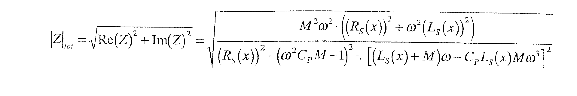
Diese ändert sich als Funktion des Abstandes zum Armierungseisen. Vor allem macht sich die Abstandsabhängigkeit in einer Änderung des äquivalenten Serienwiderstandes und der Sensorinduktivität bemerkbar, wie in der Figur 9C graphisch dargestellt und in der abschließenden Formel des Abschnitts 8.8 ausgedrückt wird.This changes as a function of the distance to the reinforcing iron. Especially the distance dependence turns into a change of the equivalent Series resistance and the sensor inductance noticeable, as in the figure 9C graphically and in the final formula of section 8.8 is expressed.
Bei Anregung bei der Resonanzfrequenz ist die Impedanz des gesamten Schwingkreises, d.h. der Sensorvorrichtung mit dem Übertrager, rein ohmsch. Der Imaginärteil fällt weg. Wird der Schwingkreis mit einer konstanten Stromamplitude betrieben, kann über eine Messung der Spannungsamplitude über dem Koppeltransformator ohne weiteres auf die Impedanz geschlossen werden.When excited at the resonant frequency, the impedance of the entire Resonant circuit, i. the sensor device with the transformer, purely ohmic. Of the Imaginary part falls away. If the resonant circuit with a constant Current amplitude operated, can via a measurement of the voltage amplitude over the coupling transformer readily to the impedance closed become.
Die folgende Tabelle zeigt die Vor- und Nachteile einiger Impedanzmeßverfahren
auf, die für die Messung der Impedanz einer in einer Bohrkrone angeordneten
Sensorspule, welche sich beispielsweise durch Annäherung an ein Eisen ändert,
anwendbar sind. Weitere Angabe zu den aufgezeigten Impedanzmeßverfahren sind
in "The Impedance Measurement Handbook: A Guide to Measurement
Technologies and Techniques" zu finden, das von der Firma Agilent Technologies
Co. Ltd. beispielsweise unter http://cp.literature.agilent.com/litweb/pdf/5950-3000.pdf
veröffentlicht wurde.
Die Nähe eines ferromagnetischen Gegenstands läßt sich auch über die Änderung der Resonanzfrequenz des aus der Sensorvorrichtung und dem Übertrager bestehenden Gesamtsystems ermitteln. Da eine lineare Abhängigkeit zwischen dem Meß- bzw. Auswertesignal und dem Abstand zwischen Eisen und Spule nicht notwendig ist, wenn primär eine möglichst frühe Detektion eines Armierungseisen zum Ziel gesetzt wird, ist die Resonanzfrequenz eine sinnvolle und empfindliche MeßgrößeThe proximity of a ferromagnetic object can also be determined by the change the resonant frequency of the sensor device and the transformer determine the existing overall system. Because a linear dependence between the measuring or evaluation signal and the distance between iron and coil not is necessary if primarily the earliest possible detection of a reinforcing iron is set to the goal, the resonance frequency is a meaningful and sensitive measured variable
Im dargestellten Ausführungsbeispiel der Figur 6A wird die Resonanzfrequenz mittels eines f/V-Konverters (f/V = "frequency to voltage", d.h. Frequenz-Spannung-Wandlers) über einen A/D-Wandler eines Mikrokontrollers oder über einen direkten Zählereingang (Counter) des Mikrokontrollers gemessen. Eine Absenkung der Resonanzfrequenz deutet auf ein Armierungseisen hin.In the illustrated embodiment of Figure 6A, the resonant frequency by means of an f / V converter (f / V = "frequency to voltage", i.e. frequency-to-voltage converter) via an A / D converter of a microcontroller or over measured a direct counter input (counter) of the microcontroller. A Lowering the resonance frequency indicates a reinforcing iron.
Der Signalwert, der schlußendlich ausgewertet wird, ist die Differenz der
Resonanzfrequenz ohne Kopplung durch ein Armierungseisen (Offset,
Anfangsfrequenz) und der Resonanzfrequenz bei Anwesenheit eines
Armierungseisens.
Zu den mathematischen Hintergründen des Ausführungsbeispiels der Figur 6A findet sich Näheres im Abschnitt "Gleichungen".The mathematical background of the embodiment of Figure 6A see the section "Equations" for details.
Analog dem in Figur 6A abgebildeten Blockschaltbild zeigt das in Figur 7A abgebildete Blockschaltbild eine exemplarische Realisierung eines mit einer induktiven Sensor- sowie einer entsprechenden Auswertevorrichtung ausgestatteten Bohrsystems 700. Dabei wird eine Spule 722, die eine erfindungsgemäße, von einer Bohrkrone 710 umfaßte Sensorvorrichtung darstellt, über einen transformatorischen Übertrager 741, die eine Signalübertragung beispielsweise von der Bohrkrone 710 zur Antriebsmaschine oder umgekehrt ermöglicht, durch einen Oszillator 720 in Resonanz angeregt. Dies kann zum Beispiel durch einen einfachen RLC-Oszillator, der automatisch in Resonanz schwingt oder durch Anregung eines Schwingkreises mit einer konstanten Frequenz ω0 beispielsweise mit einem Rechteckstrom erfolgen. Um den Kreis in diesem Fall in Resonanz anzuregen, wird die Phase zwischen Strom und Spannung auf Null geregelt.Analogous to the block diagram depicted in FIG. 6A, the block diagram depicted in FIG. 7A shows an exemplary realization of a drilling system 700 equipped with an inductive sensor and a corresponding evaluation device. In this case, a coil 722, which represents a sensor device according to the invention encompassed by a drill bit 710, is transferred a transformer transformer 741, which allows signal transmission, for example from the drill bit 710 to the prime mover or vice versa, excited by an oscillator 720 in resonance. This can be done for example by a simple RLC oscillator, which automatically resonates or by excitation of a resonant circuit with a constant frequency ω 0, for example, with a square wave. In order to stimulate the circuit in this case, the phase between current and voltage is regulated to zero.
Kennzeichnend für die Realisierung der Figur 7A ist, daß eine Kapazität CP in Reihe mit der Übertragerinduktivität M und der Sensorinduktivität ZS geschaltet ist, so daß ein Serienschwingkreis 752 über den transformatorischen Übertrager 741 gebildet wird.Characteristic of the realization of Figure 7A is that a capacitance C P is connected in series with the Übertragerinduktivität M and the sensor inductance Z S , so that a series resonant circuit 752 via the transformer transformer 741 is formed.
Während das Blockschaltbild der Figur 7A eine aufwendige Variante darstellt, die sogar eine winkeltreue Auswertung der Meßsignale ermöglicht, zeigt Figur 7B eine vereinfachte Variante, bei der als Beispiel lediglich die Amplitude und die Frequenz des Oszillatorsignals sowie die Motor- bzw. Antriebsdrehzahl erfaßt werden. Auch im Ausführungsbeispiel der Figur 7B wird ein Serienschwingkreis 752 über den transformatorischen Übertrager 741 gebildet.While the block diagram of Figure 7A represents a complex variant, the even allows an angle-faithful evaluation of the measured signals, Figure 7B shows a simplified variant, in the example only the amplitude and the Frequency of the oscillator signal and the engine or drive speed detected become. Also in the embodiment of Figure 7B is a series resonant circuit 752 via the transformer transformer 741 formed.
Näheres zu den mathematischen Hintergründen des Ausführungsbeispiels der Figuren 7A und 7B findet sich im Abschnitt "Gleichungen".More about the mathematical background of the embodiment of Figures 7A and 7B can be found in the section "equations".
Figur 8A zeigt ein den Figuren 6A, 7A und 7B analoges Ausführungsbeispiel der Erfindung, bei dem allerdings der Signalweg zwischen der als Sensorvorrichtung agierende Sensorspule 822 und einer Meß- und Auswerteschaltung über einen kapazitiven Übertrager 842 verläuft. FIG. 8A shows an exemplary embodiment analogous to FIGS. 6A, 7A and 7B Invention in which, however, the signal path between the sensor as a device acting sensor coil 822 and a measuring and evaluation circuit via a capacitive transformer 842 runs.
Wie ein transformatorischer Übertrager ermöglicht ein kapazitiver Übertrager 842 eine Signalübertragung zwischen einer Antriebsmaschine und einer relativ zur Antriebsmaschine rotierenden Bohrkrone. Zum Beispiel läßt sich das kapazitive Kopplungselement in der Werkzeugaufnahme in Form eines Zylinderkondensators als radiale Ausführungsform oder Plattenkondensators als axiale Ausführungsform unterbringen. Um die Einflüsse von Verschmutzungen gering zu halten, kann z.B. Kühlwasser als Material mit hoher Dielektrizitätskonstante als Dielektrikum zwischen den Platten verwendet werden.Like a transformer transformer, a capacitive transformer 842 allows a signal transmission between a prime mover and a relative to Drive machine rotating drill bit. For example, the capacitive can be Coupling element in the tool holder in the form of a cylindrical capacitor as radial embodiment or plate capacitor as axial Accommodate embodiment. To minimize the effects of contamination can hold, e.g. Cooling water as a material with a high dielectric constant as Dielectric be used between the plates.
Näheres zu den mathematischen Hintergründen des Ausführungsbeispiels der Figur 8A findet sich im Abschnitt "Gleichungen".More about the mathematical background of the embodiment of Figure 8A is found in the section "Equations".
Wirbelstromsensoren sind ein Standard-Werkzeug für NDT (non-destructive testing, zu deutsch: zerstörungsfreie Prüfung) von elektrisch leitenden, insbesondere metallischen Strukturen. Damit werden z.B. im Flugzeugbau die tragenden Elemente auf Risse untersucht. Ein Wirbelstromsensor reagiert sowohl auf die Permeabilität als auch auf die Induktivität des Targets. Näheres zum Thema Wirbelstrommessung kann beispielsweise in Scott D. Welsby and Tim Hitz. Nov. 1997, "True Position Measurement with Eddy Current Technology," Sensors, Vol. 14, No. 11:30-40 gefunden werden.Eddy current sensors are a standard tool for NDT (non-destructive testing: non-destructive testing) of electrically conductive, in particular metallic structures. Thus, e.g. in aircraft construction the carrying elements examined for cracks. An eddy current sensor reacts both on the permeability as well as on the inductance of the target. More about For example, eddy current measurement can be found in Scott D. Welsby and Tim Hitz. Nov. 1997, "True Position Measurement with Eddy Current Technology," Sensors, Vol. 14, no. 11: 30-40 can be found.
Figur 9A zeigt eine allgemeine Anordnung zur Wirbelstrommessung.Figure 9A shows a general arrangement for eddy current measurement.
Ein Wirbelstromsensor stellt eine bevorzugte Sensorvorrichtung der Erfindung dar. Eine entsprechende Bohrkrone bzw. ein entsprechendes Bohrsystem sowie eine entsprechende Meß- und Auswertevorrichtung lassen sich mittels der nachstehenden Merkmale in bevorzugter Weise realisieren.An eddy current sensor provides a preferred sensor device of the invention a corresponding drill bit or a corresponding drilling system and a corresponding measuring and evaluation device can be by means of implement the following features in a preferred manner.
Sensorprinzip und physikalischer Effekt: Änderung der Impedanz Z einer Spule durch Bildung von Wirbelströmen in der Nähe der Sensorspule, vor allem der Realteil des Spulen-Target-Systems ändert, Detektion von elektrisch leitenden Materialien möglich. Sensor principle and physical effect: change in the impedance Z of a coil by formation of eddy currents near the sensor coil, especially the real part of the coil target system changes, detection of electrically conductive materials possible.
Koppler, Übertragung auf die rotierende Bohrkrone: Koppeltransformator. Coupler, transfer to the rotating drill bit: Coupling transformer.
Meßelektronik: LRC-Schwingkreis mit hochfrequenter (5-50kHz) Konstantstromquelle. Measuring electronics: LRC resonant circuit with high-frequency (5-50kHz) constant current source.
Meßsignal(e): Für die Auswertung der Impedanz: Spannung (und eventuell Phase relativ zum Strom) über der primären Koppelspule. Für die Auswertung der Resonanzfrequenz: Spannung über der Primärspule des Koppeltransformators über einen Frequenz-Spannungswandler. Zusätzlich: Motordrehzahl über einen Hallsensor am Rotor des Gerätes. Measurement signal (s): For the evaluation of the impedance: voltage (and possibly phase relative to the current) across the primary coupling coil. For the evaluation of the resonance frequency: Voltage across the primary coil of the coupling transformer via a frequency-voltage converter. In addition: engine speed via a Hall sensor on the rotor of the device.
Signalauswertung: Auswertung der Meßspannung synchron zur Motordrehzahl: Darstellung des Meßsignals als Funktion des Bohrkronenwinkels und Kumulierung der Meßsignale, Wegmitteln des DC-Untergrundes und des Rauschens, Festlegen einer Schwelle und Anzeige. Signal evaluation: Evaluation of the measuring voltage synchronous to the motor speed: Representation of the measuring signal as a function of the drill bit angle and cumulation of the measuring signals, moving away of the DC background and noise, setting a threshold and display.
Das in Figur 9B dargestellte Blockschaltbild zeigt eine Realisierungsmöglichkeit einer erfindungsgemäßen Bohrkrone 910 mit Wirbelstromsensor als Sensorvorrichtung im Rahmen eines Bohrsystems mit einer entsprechenden Meß- und Auswertevorrichtung.The block diagram shown in FIG. 9B shows a possible realization a drill bit 910 according to the invention with eddy current sensor as Sensor device in the context of a drilling system with a corresponding measuring and evaluation device.
Die Hauptkomponente des Wirbelstromsensors bildet eine Sensorspule 922, deren hauptsächlich induktive Impedanz ZS beispielsweise zusammen mit der ebenfalls hauptsächlich induktiven Impedanz M eines transformatorischen Übertragers 941 und einer Kapazität Cp einen LRC-Schwingkreis 952 bildet.The main component of the eddy current sensor forms a sensor coil 922, the mainly inductive impedance Z S, for example, together with the also mainly inductive impedance M of a transformer transformer 941 and a capacitor Cp LRC resonant circuit 952 forms.
Die Meßvorrichtung umfaßt einen herkömmlichen Oszillator 920, der den LRC-Schwingkreis
952 mit einer gegebenen Frequenz f 0 und mit konstanter
Stromamplitude I 0 anregt. Die Schwingfrequenz ist entweder durch die
Resonanzfrequenz des LRC-Schwingkreises 952 bestimmt, oder wird als
erzwungene Schwingung durch den Mikrokontroller vorgegeben. Beispielsweise
über einen Gleichrichter mit nachgeschaltetem Tiefpaßfilter wird die
Spannungsamplitude der resultierenden Schwingung des LRC-Schwingkreises 952
gemessen. In einem als Auswertevorrichtung fungierenden Mikrokontroller wird
dann die Impedanz berechnet:
Um eine winkeltreue Auswertung und entsprechende Anzeige zu ermöglichen kann
gleichzeitig ein Drehzahlsignal gemessen werden, das numerisch im
Mikrocontroller zum aktuellen Drehwinkel integriert wird. Ausgewertet wird also:
Dabei repräsentieren:
- ϕ drill
- Drehwinkel der Bohrkrone
- ω rot
- Winkelgeschwindigkeit des Rotors
- ü:
- Übersetzungsverhältnis zwischen Rotor und Bohrkrone, hängt vom gewählten Gang ab
- φ drill
- Angle of rotation of the drill bit
- ω red
- Angular velocity of the rotor
- ü:
- Gear ratio between rotor and drill bit depends on the selected gear
Näheres zu den mathematischen Hintergründen des Ausführungsbeispiels der Figur 9B findet sich im Abschnitt "Gleichungen".More about the mathematical background of the embodiment of Figure 9B is found in the section "Equations".
Für Messungen mittels des Wirbelstromsensors der Figuren 5A und 5B eignet sich insbesondere die kostengünstige Treiberschaltung der Figur 9D nach Steven D. Roach, "Designing and Building an Eddy Current Position Sensor", Sensor Magazine, Sept. 1998, welche Veröffentlichungsstelle Näheres zu dieser Treiberschaltung enthält.For measurements by means of the eddy current sensor of FIGS. 5A and 5B, it is suitable in particular the cost driver circuit of Figure 9D to Steven D. Roach, "Designing and Building on Eddy Current Position Sensor", Sensor Magazine, Sept. 1998, which publication office is more about this Driver circuit contains.
Eine einfache und kostengünstige Oszillatorschaltung für eine solche
Treiberschaltung ist ein LC-Logik-Gate-Oszillator, der CMOS-Logikgatter
verwendet. Dieser kann, wie gezeigt, auf der Basis zweier Inverter realisiert
werden. Die beiden Inverter produzieren eine starke positive
Spannungsverstärkung. Daher oszilliert die Schaltung bei einer Frequenz, bei der
die Phasenverschiebung des resonanten Sensors gerade verschwindet. Die
Ausgangsspannung ist eine Rechtecksspannung, deren Frequenz eine Funktion
des Abstandes x zwischen der Spule und dem Armierungseisen ist. Der
Frequenzhub dieser Schaltung beträgt ungefähr 2.1 über den die verschiedenen
Abstände zwischen Spule und Armierungseisen. Dies läßt sich mathematisch
ausdrücken als:
Zwecks Auswertung dieses Meßsignals, d.h. dieser Ausgangsspannung, kann beispielsweise ein Mikrocontroller als Auswertevorrichtung die Frequenz der Ausgangsspannung über einen Zählereingang, einen sogenannten Counter-Eingang, digitalisieren, der die Ausgangspulse pro Zeiteinheit zählt.For the purpose of evaluating this measurement signal, i. this output voltage, can For example, a microcontroller as an evaluation the frequency of Output voltage via a counter input, a so-called counter input, digitize, which counts the output pulses per unit of time.
Die Resonanzfrequenz der Treiberschaltung inklusive Sensorvorrichtung ist
gegeben durch:
Dabei bedeuten:
Der Scheinwiderstand Rs bestimmt die Amplitude des Signals am Eingang des
ersten Inverters und damit auch die Leistungsaufnahme der Treiberschaltung. Um
das Rauschen zu minimieren, ist es sinnvoll, die Treiberschaltung so zu gestalten,
daß dieses Signal am Eingang des ersten Inverters so groß wie möglich ist. Je
kleiner der Wert von RS ist, desto größer ist dieses Signal, desto größer ist aber
auch die Leistungsaufnahme. In Resonanz ist die Impedanz des LC-Speicherkreises
rein ohmsch:
V pp ist die Amplitude der fundamentalen Harmonischen des Rechtecksignals am Ausgang. Es genügt, nur diese erste Harmonische zu betrachten, da RS und der LC-Kreis einen Bandpaßfilter um die Oszillationsfrequenz bilden. Dieser Filter dämpft alle Komponenten außer der fundamentalen Komponente. Sinnvoll ist, die Scheitel-zum-Scheitel-Amplitude (Peak-to-Peak-Amplitude) Vpp mindestens so groß wie die halbe Versorgungsspannung VDD zu wählen, wenn die Spule unbelastet ist, d.h. wenn kein Armierungseisen in der Nähe ist. Diese Regel bedingt, daß RS ≈ Rres, wobei Rres im unbelasteten Zustand bestimmt wird, d.h. ohne Armierungseisen in der Nähe. Je höher der Widerstand bei Resonanz ist, desto weniger Leistung ist für den Betrieb des Sensors notwendig. Der Widerstand steigt mit wachsender Frequenz, wachsender Induktivität und höherer Güte Q. V pp is the amplitude of the fundamental harmonics of the square wave signal at the output. It suffices to consider only this first harmonic since R S and the LC circuit form a bandpass filter around the oscillation frequency. This filter attenuates all components except the fundamental component. It makes sense to select the peak-to-peak amplitude Vpp at least as large as half the supply voltage V DD when the coil is unloaded, ie, when no reinforcing iron is in the vicinity. This rule implies that R S ≈ R res , where R res is determined in the unloaded state, ie without any reinforcing iron in the vicinity. The higher the resistance at resonance, the less power is required for the operation of the sensor. The resistance increases with increasing frequency, increasing inductance and higher Q quality.
Die Frequenzantwort eines Wirbelstromsensors hängt sowohl von der Leitfähigkeit als auch von der Permeabilität der Umgebung es Sensors, insbesondere eines zu detektierenden Targets ab.The frequency response of an eddy current sensor depends on both the conductivity as well as the permeability of the environment it sensor, in particular one to detecting targets.
Eine alternative Meß- und Auswerteschaltung stellen die Näherungsschalter der OM-Typenreihe der Firma Philips dar.An alternative measuring and evaluation circuit provide the proximity switches of OM series from Philips.
Figur 9E zeigt als Beispiel dieser Typenreihe den Näherungsschalter OM 286. Der mit T1, D1 arbeitende Oszillator schwingt auf einer Frequenz, die durch C1 und die Spule N1, N2 gegeben ist. Wird die Spule beispielsweise durch Annäherung eines Armierungseisens gedämpft, reißen die Schwingungen ab, der Arbeitspunkt von T1 verschiebt sich, und der aus T2, T3 bestehende Schmitt-Trigger schaltet. Über die Leistungsstufe (T4) kann dann z.B. ein Relais geschaltet oder eine LED betrieben. Über den Widerstand R läßt sich die Empfindlichkeit des Näherungssensors einstellen.FIG. 9E shows, as an example of this type series, the proximity switch OM 286 oscillator operating at T1, D1 oscillates at a frequency determined by C1 and the coil N1, N2 is given. If the coil, for example, by approach damped by a reinforcing iron, the vibrations break off, the working point T1 shifts, and the Schmitt trigger consisting of T2, T3 switches. Over the power stage (T4), then, e.g. a relay switched or an LED operated. About the resistance R, the sensitivity of the Adjust proximity sensor.
Ein Zwei-Draht-Hall-Sensor stellt eine bevorzugte Sensorvorrichtung der Erfindung dar. Eine entsprechende Bohrkrone bzw. ein entsprechendes Bohrsystem sowie eine entsprechende Meß- und Auswertevorrichtung lassen sich mittels der nachstehenden Merkmale in bevorzugter Weise realisieren.A two-wire Hall sensor provides a preferred sensor device of the Invention. A corresponding drill bit or a corresponding Drilling system and a corresponding measuring and evaluation can be realize by means of the following features in a preferred manner.
Sensorprinzip und physikalischer Effekt: Änderung der Hallspannung in einem Hall-Element durch Änderung der Flußdichte. Sensor principle and physical effect: Change the Hall voltage in a Hall element by changing the flux density.
Koppler, Übertragung auf die rotierende Bohrkrone: Schleifring, Erdpotential. Coupler, transfer to the rotating drill bit: slip ring, earth potential.
Meß- und Auswerteelektronik: Über einen Shuntwiderstand wird die Stromaufnahme des Hall-Elements gemessen, nachfolgend ein Tiefpaßfilter, Verstärker und A/D-Wandler, Mikroprozessor. Measuring and evaluation electronics: A shunt resistor is used to measure the current consumption of the Hall element, followed by a low-pass filter, amplifier and A / D converter, microprocessor.
Meßsignal(e): Hallspannung. Zusätzlich: Motordrehzahl über einen Hallsensor am Rotor des Gerätes. Measuring signal (s): Hall voltage. In addition: engine speed via a Hall sensor on the rotor of the device.
Signalauswertung: Auswertung der Meß spannung synchron zur Motordrehzahl: Darstellung des Meßsignals als Funktion des Bohrkronenwinkels und Kumulierung der Meßsignale, Wegmitteln des DC-Untergrundes und des Rauschens, Festlegen einer Schwelle und Anzeige. Signal evaluation: Evaluation of the measuring voltage synchronous to the motor speed: Representation of the measuring signal as a function of the Bohrkronenwinkels and cumulation of the measured signals, moving away of the DC background and noise, setting a threshold and display.
Zwei-Draht-Hall-Sensoren liefern ein Meßsignal in Form eines Stromverbrauchs. Sie verwenden eine interne Stromquelle, die je nach Stärke des Magnetfeldes verändert wird. Über einen Serienwiderstand kann der Strom und damit das Magnetfeld als Spannung gemessen werden. In anderen Worten ändert eine integrierte Hall-Sensor-Schaltung ihre Stromaufnahme, d.h. ihren DC-Widerstand über der Quelle. Ändert sich die magnetische Flußdichte in der Nähe des Sensors, so ändert auch seine Stromaufnahme. Diese kann beispielsweise mit einem Serienwiderstand gemessen werden.Two-wire Hall sensors provide a measurement signal in the form of power consumption. They use an internal power source, depending on the strength of the magnetic field is changed. About a series resistor, the current and thus the Magnetic field can be measured as a voltage. In other words, one changes integrated Hall sensor circuit, their current consumption, i. their DC resistance over the source. Does the magnetic flux density change near the sensor, so also changes its power consumption. This can, for example, with a Series resistance can be measured.
Figur 10 zeigt eine exemplarische Realisierung einer erfindungsgemäßen Bohrkrone 1010 mit einer Sensorvorrichtung 1020 auf der Basis eines Zwei-Draht-Hall-Sensors 1021H, wobei die Bohrkrone 1010 Teil eines mit einer entsprechenden Auswertevorrichtung ausgestatteten Bohrsystems 1000 bildet. Die Sensorvorrichtung 1020 umfaßt auch einen Permanentmagneten 1028, der als Magnetfeldquelle für den Hall-Sensor 1021H fungiert.FIG. 10 shows an exemplary realization of a device according to the invention Drill bit 1010 with a sensor device 1020 based on a two-wire Hall sensor 1021H, wherein the drill bit 1010 part of a with a corresponding evaluation device equipped drilling system 1000 forms. The sensor device 1020 also includes a permanent magnet 1028, referred to as Magnetic field source for the Hall sensor 1021H acts.
Als sinnvolle Art der Signalübertragung zwischen der mit der Bohrkrone 1010 rotierenden Sensorvorrichtung 1020 und der beispielsweise in einer Antriebsmaschine angeordneten Meßvorrichtung, sieht das Ausführungsbeispiel die Verwendung eines Schleifrings 1043 vor. Dafür kann am oberen Schaft der Bohrkrone 1010 ein isolierter Kollektor, d.h. ein Schleifring 1043, angebracht werden, der mit dem positiven Potential des Hall-Sensors 1021H isoliert verbunden ist. Das Erdpotential 1144 für die Versorgung des Hall-Sensors 1021H wird über die Gerätemasse und über die Bohrkrone 1010 selbst geführt. Dies erspart einen Schleifring. Der Schleifring 1043 wird beispielsweise mittels Bürsten in der Werkzeugaufnahme der Antriebsmaschine abgegriffen.As a sensible way of signal transmission between the 1010 with the drill bit rotating sensor device 1020 and the example in a Drive machine arranged measuring device, sees the embodiment the use of a slip ring 1043 ago. This can be done on the upper shaft of the Drill bit 1010 an isolated collector, i. a slip ring 1043 mounted Be isolated with the positive potential of the Hall sensor 1021H connected is. The earth potential 1144 for the supply of the Hall sensor 1021H is guided over the device ground and over the drill bit 1010 itself. This saves a slip ring. The slip ring 1043 is for example by means of brushes tapped in the tool holder of the drive machine.
Erfindungsgemäß kann anstelle des Schleifrings 1043 ein Koppeltransformator zusammen mit einem Gleichrichter auf der Sekundärseite, d.h. auf der an der Bohrkrone montierten Seite des Trafos, Verwendung finden. Der Gleichrichter versorgt den Hall-Sensor mit Strom. Die Stromaufnahme des Hall-Sensors hängt von der magnetischen Flußdichte ab. Die Stromaufnahme kann über die Leistungsaufnahme (oder auch über den Strom) auf der Primärseite des Übertragers gemessen werden.According to the invention, instead of the slip ring 1043, a coupling transformer together with a rectifier on the secondary side, i. on the at the Drill bit mounted side of the transformer, find use. The rectifier supplies power to the Hall sensor. The current consumption of the Hall sensor hangs from the magnetic flux density. The current consumption can over the Power consumption (or over the current) on the primary side of the Be measured transformer.
Ohmsche Kontaktelemente stellen eine bevorzugte Sensorvorrichtung der Erfindung dar. Eine entsprechende Bohrkrone bzw. ein entsprechendes Bohrsystem sowie eine entsprechende Meß- und Auswertevorrichtung lassen sich mittels der nachstehenden Merkmale in bevorzugter Weise realisieren.Ohmic contact elements provide a preferred sensor device of Invention. A corresponding drill bit or a corresponding Drilling system and a corresponding measuring and evaluation can be realize by means of the following features in a preferred manner.
Sensorprinzip und physikalischer Effekt: Änderung des Widerstandes oder Überbrückung von leitenden Kontakten an den Bohrsegmenten. Sensor principle and physical effect: change of resistance or bridging of conductive contacts on the drill segments.
Koppler, Übertragung auf die rotierende Bohrkrone: Schleifring, Erdpotential. Coupler, transfer to the rotating drill bit: slip ring, earth potential.
Meß- und Auswerteelektronik: Über einen Shuntwiderstand wird die Stromaufnahme gemessen, nachfolgend ein Tiefpaßfilter, Verstärker und A/D-Wandler, Mikroprozessor. Measuring and evaluation electronics: A shunt resistor measures the current consumption, followed by a low-pass filter, amplifier and A / D converter, microprocessor.
Meßsignal(e): Widerstandsänderung an den Bohrsegmenten. Measurement signal (s): Resistance change at the drill segments.
Signalauswertung: Auswertung der Meßspannung synchron zur Motordrehzahl: Darstellung des Meßsignals als Funktion des Bohrkronenwinkels und Kumulierung der Meßsignale, Wegmitteln des DC-Untergrundes und des Rauschens, Festlegen einer Schwelle und Anzeige. Signal evaluation: Evaluation of the measuring voltage synchronous to the motor speed: Representation of the measuring signal as a function of the drill bit angle and cumulation of the measuring signals, moving away of the DC background and noise, setting a threshold and display.
Figur 11 zeigt eine exemplarische Realisierung einer erfindungsgemäßen Bohrkrone 1110 mit einer Sensorvorrichtung auf der Basis von ohmschen Kontaktelementen 1127. Solche Kontaktelemente 1127 können beispielsweise durch in einer abbauenden Matrix 416 der Bohrkrone 1110 angeordnete, leitende Elemente 425 realisiert werden, wie in den Figuren 4A bis 4F gezeigt wird.FIG. 11 shows an exemplary realization of a device according to the invention Drill bit 1110 with a sensor device based on ohmic Contact elements 1127. Such contact elements 1127 can, for example by conducting in a degrading matrix 416 of the drill bit 1110, conductive Elements 425 are realized, as shown in Figures 4A to 4F.
Die Verwendung ohmscher Kontaktelemente stellt eine einfache und robuste Möglichkeit für die Eisendetektion dar. Ein Nachteil der Methode ist, daß eine Detektion des Eisens erst beim Anbohren erfolgen kann. Will man das Eisen nicht verletzen, so muß beispielsweise auf eine induktive (Spule), magnetische (Hall) oder Wirbelstrommethode zurückgegriffen werden.The use of ohmic contact elements provides a simple and robust Possibility for the iron detection dar. A disadvantage of the method is that a Detection of iron can only be done during drilling. If you do not want the iron For example, an inductive (coil), magnetic (Hall) or eddy current method are used.
Da ein wie beschriebener ohmscher Kontakt beispielsweise auf der Basis von in abbauenden Elementen der Bohrkrone versehenen leitenden Bereichen in der Praxis nicht mit einem idealer Schalter vergleichbar ist, ist es sinnvoll, das Meßsignal einer Signalaufbereitung, zum Beispiel einer Filterung, insbesondere einer Bandpaßfilterung, zu unterziehen.Since an ohmic contact as described, for example, on the basis of in degrading elements of the drill bit provided conductive areas in the Practice is not comparable with an ideal switch, it makes sense that Measuring signal of a signal conditioning, for example, a filtering, in particular a bandpass filtering to undergo.
Analog der Figur 10 zeigt Figur 11 ein Ausführungsbeispiel, bei dem eine Signalübertragung zwischen der mit der Bohrkrone 1010 rotierenden Sensorvorrichtung und einer beispielsweise in einer Antriebsmaschine angeordneten Meßvorrichtung über einen Schleifring 1143 erfolgt. Schutzelemente gegen Überspannung beim Anbohren an ein Spannungsführendes Kabel sind nicht gezeichnet.11 shows an embodiment in which a Signal transmission between the rotating with the drill bit 1010 Sensor device and one example in a prime mover arranged measuring device via a slip ring 1143 takes place. protection elements against overvoltage when drilling to a live cable are not drawn.
Ein Stromkreis von der Meß- und Auswertevorrichtung beispielsweise in der Antriebsmaschine zu den ohmschen Kontaktelementen in der Bohrkrone kann über zwei Schleifringe erfolgen, die jeweils einen Signalpfad zur bzw. von der Bohrkrone ermöglichen. Um auf einen zweiten Schleifring verzichten zu können, kann der Stromkreis jedoch, wie dargestellt, über das Erdpotential des Untergrunds 1144 geschlossen werden.A circuit of the measuring and evaluation device, for example in the Drive machine to the ohmic contact elements in the drill bit can via two slip rings, each having a signal path to or from the Allow drill bit. In order to be able to do without a second slip ring, However, the circuit can, as shown, on the ground potential of the Underground 1144 closed.
Erfindungsgemäβ kann anstelle des Schleifrings 1143 ein Koppeltransformator verwendet werden. Der Transformator wird je nach dem Widerstand der Kontaktelemente belastet oder auf der Sekundärseite sogar kurzgeschlossen. Diese Änderung des Widerstands kann über die Stromaufnahme auf der Primärseite gemessen werden.According to the invention, instead of the slip ring 1143, a coupling transformer be used. The transformer will vary depending on the resistance of the Contact elements loaded or even short-circuited on the secondary side. This change in resistance can be due to the power consumption on the Primary side are measured.
Jede lokale Meßmethode, d.h. jede lokale Meßsonde, die an einem Punkt des vorderen Endes der Bohrkrone angebracht ist, erzeugt ein zum Drehwinkel der Bohrkrone periodisches, pulsartiges Signal. Ob es sich nun um einen Hall-Sensor oder um einen induktiven Näherungssensor handelt, spielt dabei eigentlich keine Rolle. Im ersten Fall werden tatsächlich Spannungspulse erzeugt, im zweiten Fall sind es eher pulsartige Frequenzänderungen, die detektiert werden müssen. Im Falle eines ohmschen Kontaktes, d.h. eines Schalters, sind es Widerstandsänderungen, die wiederum beispielsweise als Spannungsänderung detektiert werden können. Die Signalauswertung - geschehe sie nun digital in einem Mikrokontroller oder analog mit einer diskreten Filter- und Verstärkerschaltung - ist im wesentlichen also eine Peak-Detektion, d.h. eine Signalscheitel-Detektion. Je nachdem an welcher Stelle und unter welchem Winkel die Bohrkrone ein Target nähert, d.h. z.B. je nachdem an welcher Stelle und unter welchem Winkel ein oder mehrere Armierungseisen durch die Bohrkrone angeschnitten werden, ergeben sich unterschiedlich lange Pulsbreiten.Any local measurement method, i. any local probe at one point of the attached to the front end of the drill bit, generates a rotation angle of the Drill bit periodic, pulse-like signal. Whether it is a Hall sensor or is an inductive proximity sensor, actually plays no Role. In the first case, voltage pulses are actually generated, in the second case it is rather pulse-like frequency changes that have to be detected. in the Case of ohmic contact, i. a switch, it is Resistance changes, which in turn, for example, as a voltage change can be detected. The signal evaluation - they now happen digitally a microcontroller or analog with a discrete filter and Amplifier circuit - is essentially a peak detection, i. a Signal peak detection. Depending on where and under which Angle the drill bit is approaching a target, i. e.g. depending on where and at what angle one or more reinforcing bars through the Drill bit are cut, resulting in different lengths pulse widths.
Im Folgenden wird unter Bezugnahme der Figuren 15A-15D eine Simulation fünf unterschiedlicher Situationen diskutiert. Dabei wird angenommen, daß ein Armierungseisen an fünf verschiedenen Stellen relativ zum Zentrum einer Bohrkrone angebohrt wird. Figur 15A zeigt diese Simulationsannahme. Dargestellt wird der Umriß einer Bohrkrone 1510 sowie fünf Armierungseisen 1581A-1581E. Die Schnittpunkte eines jeweiligen Armierungseisens 1581 durch die Bohrkrone 1510 sind durch Punkte gekennzeichnet.In the following, with reference to Figs. 15A-15D, a simulation becomes five different situations discussed. It is assumed that a Reinforcing iron at five different places relative to the center of a Drill bit is drilled. Figure 15A shows this simulation assumption. shown is the outline of a drill bit 1510 and five reinforcing bars 1581A-1581E. The intersections of a respective Armierungseisens 1581 through the drill bit 1510 are marked by dots.
Figur 15B zeigt die simulierte, normierte Widerstandsänderung eines mittels ohmscher Kontakte gewonnenen Meßsignals als Funktion des Drehwinkels der Bohrkrone 1510 in rad. Um die simulierten Signalverläufe der jeweiligen Armierungseisenpositionen klar voneinander darstellen zu können, sind sie unterschiedlich normiert. Somit entsprechen die dargestellten Meßsignalverläufe von oben nach unten dem durch Detektion des jeweiligen Armierungseisen 1581A bis 1581E zu erwartenden Meβsignalverlauf. Die unterste Kurve entspricht somit einer Detektion des Armierungseisens 1581E. Die im Meßsignalverlauf auftretenden Pulse sind breit und relativ nahe beieinander. Je näher das Armierungseisen zum Zentrum der Bohrkrone hin verschoben wird, desto symmetrischer wird die Pulsverteilung, und desto kürzer werden die Pulse.Figure 15B shows the simulated, normalized resistance change of a ohmic contacts obtained measurement signal as a function of the rotation angle of the Drill bit 1510 in rad. To the simulated waveforms of each Being able to clearly represent reinforcing iron positions from each other is what they are standardized differently. Thus, the illustrated Meßsignalverläufe correspond from top to bottom by detecting the respective reinforcing iron 1581A to 1581E expected Meβsignalverlauf. The lowest curve thus corresponds a detection of armouring 1581E. The in Meßsignalverlauf occurring pulses are wide and relatively close together. The closer that Reinforcing iron is moved towards the center of the drill bit, the more The pulse distribution becomes more symmetrical, and the pulses become shorter.
Figur 15C stellt eine analoge Situation dar, bei der keine Widerstandswerte, sondern (normierte) Spannungswerte eines (digitalen, d.h. analoger Hall-Sensor mit Schmitt-Trigger) Hall-Sensors simuliert werden. Die Pulse sind vergleichbar, nur ist das Vorzeichen umgekehrt.FIG. 15C illustrates an analogous situation in which no resistance values, but (normalized) voltage values of a (digital, i.e. analogue Hall sensor with Schmitt trigger) Hall sensors can be simulated. The pulses are comparable, only the sign is reversed.
Analog zu den Figuren 15B und 15C zeigt Figur 15D in schematischer Darstellung die simulierte Frequenzänderung eines beispielsweise in einem abbauenden Element der Bohrkrone 1510 angeordneten, induktiven Näherungssensors. Um die Frequenzänderung visualisieren zu können, wurde die Frequenz sehr tief gewählt, was nicht der Realität entspricht. Wie oben näher beschrieben, kann die Frequenz über einen Counter-Eingang eines Mikrokontrollers direkt digitalisiert und damit in einen numerischen Wert übersetzt werden. Für eine analoge Pulsdetektion bietet sich ein Frequenz-Spannungs-Wandler (f/V-Converter) an.Analogous to FIGS. 15B and 15C, FIG. 15D shows a schematic illustration the simulated frequency change of, for example, in a degrading Element of the drill bit 1510 arranged, inductive proximity sensor. To the To be able to visualize the frequency change, the frequency was chosen very low, which does not correspond to reality. As described in more detail above, the frequency digitized directly via a counter input of a microcontroller and thus be translated into a numeric value. For an analog pulse detection offers a frequency-voltage converter (f / V converter).
Aus den obigen Überlegungen und Simulationen ist ersichtlich, daß die Signalauswertung für eine lokale Meßmethode in einer zuverlässigen Peak- oder Pulsdetektion bestehen kann.From the above considerations and simulations, it can be seen that the Signal evaluation for a local measurement method in a reliable peak or Pulse detection may exist.
Eine Pulsdetektion geschieht vorzugsweise in einem Mikrokontroller. Sobald ein Peak detektiert wird, d.h. sobald die Spannung am Eingang eines A/D-Wandlers des Mikrokontrollers eine gewisse Schwelle überschritten Uthr hat, und die Länge des Pulses nicht länger als eine Viertelumdrehung Bohrkrone entspricht, gilt der Puls als detektiert. Zur Sicherheit kann noch ein zweiter Puls abgewartet werden, der ebenfalls diese Bedingungen erfüllt. Erst dann gilt das Armierungseisen als detektiert.A pulse detection is preferably done in a microcontroller. As soon as a peak is detected, ie as soon as the voltage at the input of an A / D converter of the microcontroller has exceeded a certain threshold U thr , and the length of the pulse does not correspond to drill bit longer than a quarter turn, the pulse is considered detected. For safety, a second pulse can be waited for, which also fulfills these conditions. Only then does the reinforcing iron apply as detected.
Im Falle von sehr kleinen Bohrkronen beispielsweise mit einem Durchmesser von etwa 10-20mm kann es zu Volltreffern von Armierungseisen kommen. In diesem Falle wird das Sensorsignal nicht mehr moduliert. Sollte also die Pulslänge mehr als einer halben Umdrehung der Bohrkrone entsprechen, so kann das Armierungseisen ebenfalls als detektiert gelten. Es wird in diesem Fall kein zweiter Puls abgewartet, sondern es wird direkt auf die Anwesenheit eines Armierungseisens geschlossen.In the case of very small drill bits, for example with a diameter of about 10-20mm, it can come to ricochets of rebar. In this Trap, the sensor signal is no longer modulated. So should the pulse length more can correspond to half a turn of the drill bit, so that can Reinforcing bars are also considered to be detected. It will not be in this case second pulse waited, but it is directly related to the presence of a Reinforced iron closed.
Ist ein Target detektiert worden, kann dieser Umstand dem Anwender angezeigt werden und/oder können entsprechende Aktionen einleitet werden (z.B. Motor abschalten, Vorschubmotor stoppen). Um die Pulsdauer als Funktion des Drehwinkels der Bohrkrone zu beurteilen, ist es notwendig, die Drehzahl des Motors zu kennen, was im Allgemeinen vorausgesetzt werden kann. Denn wenn ein Mikrokontroller in ein Bohrwerkzeug integriert ist, wird dieser im allgemeinen für eine Drehzahlregelung verwendet.If a target has been detected, this circumstance can be displayed to the user and / or appropriate actions can be initiated (e.g., engine switch off, stop feed motor). To the pulse duration as a function of It is necessary to estimate the rotation speed of the drill bit Knowing what can generally be assumed. Because if a microcontroller is integrated into a drilling tool, this is generally used for a speed control.
Ein robustes und bevorzugtes Auswerteverfahren für alle lokale Meßverfahren beruht auf einer synchronen Messung des Drehwinkels der Bohrkrone. Werden die Meßsignale (ob es nun eine Impedanzänderung, eine Änderung der Resonanzfrequenz oder eine Änderung des Widerstandes ist) als Funktion des Drehwinkels modulo 2π dargestellt, so werden sich immer an dem Winkel, wo beispielsweise ein Eisen detektiert wird, Signale kumulieren. Wird der Winkelbereich in z.B. zehn Sektoren ä 36° (Sektor-Klassen) eingeteilt und die mittleren Signalamplituden innerhalb eines jeweiligen Sektors summiert, so werden in Bereichen, wo sich tatsächlich ein Armierungseisen befindet, die Signale kumulieren, während das Rauschen in den übrigen Bereichen weggemittelt wird. Ein durch den Untergrund verursachten, auch "DC-Offset" genannten Gleichspannungsversatz kann einfach ermittelt und subtrahiert werden. Übersteigen die in den Sektoren aufsummierten Signale einen gewissen Schwellenwert, so wird dies beispielsweise angezeigt oder aber der Antrieb wird gestoppt.A robust and preferred evaluation method for all local measuring methods is based on a synchronous measurement of the angle of rotation of the drill bit. Become the measuring signals (whether it is an impedance change, a change of Resonant frequency or a change in resistance) as a function of Rotation angle modulo 2π represented, so will always be at the angle where For example, an iron is detected, signals accumulate. Will the Angular range in e.g. ten sectors are classified as 36 ° (sector classes) and the summed mean signal amplitudes within a respective sector, so are in areas where a reinforcing iron is actually, the Cumulate signals while the noise in the remaining areas is averaged out. An underground caused by the "DC offset" said DC offset can be easily determined and subtracted become. The signals accumulated in the sectors exceed a certain amount Threshold, this is displayed, for example, or the drive is stopped.
Steht die Maschine, so werden die aufsummierten Klassen auf Null zurückgesetzt. Das Reset kann auch per Hand durch den Anwender ausgelöst werden. Eine Alternative ist, daß die aufsummierten Signale innerhalb der Klassen mittels eines sehr langsamen Hochpaßfilters (Grenzfrequenz z.B. 15-30 sec) mitgeschleppt werden. Somit klingen die Daten automatisch nach einer gewissen Zeit ab, und es werden nur die Signaländerungen gemessen.If the machine is standing, the accumulated classes are reset to zero. The reset can also be triggered manually by the user. A Alternative is that the accumulated signals within the classes by means of a Very slow high-pass filter (cutoff frequency, for example, 15-30 sec) entrained become. Thus, the data automatically stops after a certain amount of time, and it does only the signal changes are measured.
Erschwerend für diese Methode kommt hinzu, daß sich das Gerät während des Arbeitens bewegt, d.h. nach links und rechts ausschwenkt. Dies bewirkt, daß die Klassen ein wenig verschmiert werden. Daher ist es sinnvoll, nicht zu schmale Winkelbereiche zu wählen. To make matters worse for this method is that the device during the Working moves, i. swings left and right. This causes the Classes are a little smudged. Therefore, it makes sense not to narrow Select angle ranges.
Sinnvoll ist ebenfalls eine Anzeige in Form eines Ringes aus LED um die Werkzeugaufnahme. In den Winkelbereichen, wo Eisen detektiert wurde, können die LED je nach Stärke der Detektion aktiviert werden. Dies zeigt dem Anwender nicht nur an, daß auf ein Armierungseisen gestoßen worden ist oder bald stoßen wird, sondern auch an welchem Ort sich das Armierungseisen (ungefähr) befindet.Also useful is an indicator in the form of a ring of LED around the tool holder. In the angular ranges where iron was detected, the LEDs can be activated according to the amount of detection. This not only indicates to the user that a rebar has been encountered or will soon be encountered, but also where the rebar (approximately) is located.
Selbstverständlich sind neben dem oben beschrieben, bevorzugten Winkelauswertungsverfahren auch andere, dem Fachmann bekannte Verfahren zur Winkelauswertung im Rahmen der Erfindung sinnvoll anwendbar. Hier wird auf die einschlägige Literatur zur winkelabhängigen Signalauswertung verwiesen.Of course, in addition to the above described, preferred Angle evaluation method and other methods known in the art for angle evaluation in the context of the invention useful. Here is referred to the relevant literature on the angle-dependent signal evaluation.
Der Fall, daß die Spule nicht lokal an der Stelle eines Schleifelements der Bohrkrone angebracht ist, sondern beispielsweise axial um die Bohrkrone gewickelt ist, ist vergleichbar mit einem Metalldetektor. Hierbei soll die Spule möglicht weit am vorderen Ende der Bohrkrone angebracht sein, kurz hinter den Schleifelementen. Zudem ist es vorteilhaft, wenn die Mantelfläche der Bohrkrone aus nichtmetallischem Material gefertigt ist. Faserverstärkte Verbundstoffe stellen hier eine bevorzugte Lösung dar. Dabei können die Diamantsegmente am Ende der Bohrkrone nach wie vor an einem einen metallischen Ring befestigt werden.The case that the coil is not locally in place of a grinding element of Drill bit is attached, but for example axially around the drill bit is wound, is similar to a metal detector. Here is the coil as far as possible at the front end of the drill bit, just behind the drill bit Abrasive elements. In addition, it is advantageous if the lateral surface of the drill bit made of non-metallic material. Provide fiber reinforced composites Here is a preferred solution. The diamond segments at the end of Drill bit still attached to a metallic ring.
Die Signalauswertung besteht in diesem Fall aus der Festlegung einer gewissen Mindestschwelle, die das Ausgangssignal des Metalldetektors erreichen muß, damit ein Armierungseisen als mit Sicherheit detektiert worden gilt. Metalldetektoren können ebenfalls mit Oszillatorschaltungen realisiert werden, welche mit einer Güte- oder Frequenzänderung auf die Anwesenheit von Eisen reagieren. (siehe den Abschnitt "Wirbelstromsensoren")The signal evaluation consists in this case of the determination of a certain Minimum threshold which the output signal of the metal detector must reach so that a reinforcing iron has been detected with certainty. Metal detectors can also be realized with oscillator circuits, which with a quality or frequency change to the presence of iron react. (see the section "Eddy current sensors")
Erfindungsgemäß kann die Auswertung eines von der Sensorvorrichtung direkt oder indirekt über eine vorgeschaltete Meßvorrichtung gelieferten Meßsignals in einer Meßvorrichtung oder in einer besonders für diesen Zweck vorgesehenen Auswertevorrichtung erfolgen. Die Auswertung kann allein auf der Basis des o.g. Meßsignals oder in Zusammenhang mit weiteren Parametern, insbesondere in Zusammenhang mit weiteren Bohrparametern wie Schnittgeschwindigkeit, Anpreßkraft, Wasserzufuhr, Drehmoment, etc., erfolgen. Zum Beispiel könnte die Auswertung in Abhängigkeit von vorbestimmten, gemessenen und/oder von einem Benutzer eines erfindungsgemäßen Bohrsystems gelieferten Parametern erfolgen. Das Auswertungsergebnis und/oder eines oder mehrerer der weiteren Parametern können der Meßvorrichtung und/oder der Sensorvorrichtung zurückgeführt werden, um ein besseres, insbesondere ein den Anforderungen des Benutzers angepaßtes, Auswerteergebnis zu erzielen. Zum Beispiels könnte der Benutzer über eine entsprechende Eingabevorrichtung bestimmen, ob eher eine hohe Detektionsempfindlichkeit, bei der ein Target früh, d.h. auch aus großer Entfernung, erkannt wird, oder eher eine hohe Detektionsgenauigkeit, bei der wenig "Fehlmeldungen" auftreten, erwünscht ist. Ebenfalls könnte beispielsweise die Schnittgeschwindigkeit als Parameter zur Wahl zwischen Detektionsgenauigkeit und Detektionsempfindlichkeit eingesetzt werden, wobei wenn schnell durch den Bohruntergrund gebohrt wird, eher die Empfindlichkeit der Detektion betont wird, aber wenn langsam durch den Untergrund gebohrt wird, größerer Wert auf die Detektionsgenauigkeit gelegt werden darf.According to the invention, the evaluation of a directly from the sensor device or indirectly via a preceding measuring device supplied measuring signal in a measuring device or in a specially provided for this purpose Evaluation device done. The evaluation can be done solely on the basis of the o.g. Measuring signal or in conjunction with other parameters, in particular in Related to further drilling parameters such as cutting speed, Pressing force, water supply, torque, etc., take place. For example, the Evaluation as a function of predetermined, measured and / or of a Users of a drilling system according to the invention supplied parameters. The evaluation result and / or one or more of the other parameters can be returned to the measuring device and / or the sensor device Become a better, especially a user's requirements adapted to achieve evaluation result. For example, the user might determine via an appropriate input device, if rather a high Detection sensitivity in which a target is detected early, i. also from big Distance, is detected, or rather a high detection accuracy, in which little "false messages" occur, is desired. Likewise, for example the cutting speed as a parameter to choose between Detection accuracy and detection sensitivity are used, wherein when drilled quickly through the drilling surface, rather the sensitivity the detection is emphasized, but when slowly drilled through the underground is, greater value may be placed on the detection accuracy.
Eine größere Detektionsempfindlichkeit könnte beispielsweise dadurch erreicht werden, daß mehrere im abbauenden Bereich der Bohrkrone angeordneten Sensorvorrichtungen zugeschaltet werden, während beispielsweise eine größere Detektionswinkelgenauigkeit dadurch erzielt werden könnte, daß lediglich eine in einem begrenzten Umfang der Bohrkrone detektierende Sensorvorrichtung zugeschaltet wird.A greater detection sensitivity could be achieved, for example be arranged that several in the degrading area of the drill bit Sensor devices are switched on, while, for example, a larger Detection angle accuracy could be achieved that only one in a limited extent of the drill bit detecting sensor device is switched on.
Die Meß- und Auswertevorrichtung können sowohl analoge als auch digitale Komponenten umfassen. Ebenfalls können sie in Form einer programmierbaren Hardware ausgeführt sein, deren Funktionsweise über eine entsprechende Programmsoftware bestimmt wird.The measuring and evaluation device can be both analog and digital Components include. Also they can be in the form of a programmable Hardware be executed, whose operation via an appropriate Program software is determined.
Für die Auswertung und für eine Anpassung der Auswertung ergeben sich gemäß der obigen Lehre unzählige Kombinationsmöglichkeiten, die sich im Einzelnen nicht auflisten lassen. Der Fachmann auf dem Gebiet der Meß- und Auswertevorrichtung weiß jedoch aus dieser Lehre, wie die Sensorvorrichtung sowie die Meß- und Auswertevorrichtungen der Erfindung auch außerhalb der explizit beschriebenen Lehre abgeändert werden können.For the evaluation and for an adjustment of the evaluation, it follows The above teaching innumerable possible combinations, in detail not list. The expert in the field of measuring and However, evaluation device knows from this teaching how the sensor device as well as the measuring and Auswertevorrichtungen the invention outside the can be modified explicitly described teaching.
Vorzugsweise umfaßt das Bohrsystem eine Signalisierungsvorrichtung, die in Abhängigkeit von dem Meß- und/oder Auswertesignal eine Anpassung eines oder mehreren Bohrparameters automatisch vornimmt, und/oder einem Nutzer eine Anpassung eines oder mehreren Bohrparameters wahrnehmbar signalisiert, und/oder einem Nutzer einen Austausch der Bohrkrone wahrnehmbar signalisiert, und/oder einem Nutzer die Detektion eines Targets wahrnehmbar, insbesondere visuell und winkeltreu, signalisiert, und/oder den Bohrvorgang automatisch abbricht. Vorzugsweise umfaßt die Anpassung eines oder mehreren Bohrparameters eine Anpassung des Drehmoments, der Schnittgeschwindigkeit, der Wasserzufuhr, der Anpreßkraft und/oder der Bohrleistung.Preferably, the drilling system comprises a signaling device incorporated in Depending on the measurement and / or evaluation signal an adjustment of or automatically performs a plurality of Bohrparameters, and / or a user a Adjustment of one or more drill parameters perceptibly signaled and / or a user perceive an exchange of the drill bit signals, and / or a user the detection of a target perceptible, in particular visually and angled, signaled, and / or the drilling process automatically stops. Preferably, the adaptation comprises one or more Bohrparameters an adjustment of the torque, the cutting speed, the water supply, the contact pressure and / or the drilling power.
Figur 16 zeigt in schematischer Darstellung eine Signalisierungsvorrichtung 1660 eines erfindungsgemäßen Bohrsystems 1660 gemäß einem weiteren Ausführungsbeispiel. Die dargestellte Signalisierungsvorrichtung 1660 umfaßt einen Mikrokontroller 1653 sowie eine damit verbundene Anzeigevorrichtung 1661. Der Mikrokontroller 1653 ist zudem mit einer Leistungselektronik 1671 verbunden, über die der Mikrokontroller 1653 eine dem Antrieb der Bohrkrone dienende Antriebsvorrichtung 1673 und einen dem Vorschub der Bohrkrone dienenden Vorschubvorrichtung 1672 regeln kann.FIG. 16 shows a schematic illustration of a signaling device 1660 a drilling system according to the invention 1660 according to another Embodiment. The illustrated signaling device 1660 comprises a microcontroller 1653 and a display device connected thereto 1661. The microcontroller 1653 is also equipped with 1671 power electronics connected via the microcontroller 1653 a drive the drill bit serving drive device 1673 and the feed of the drill bit Serving feed device 1672 can regulate.
Vorzugsweise ist die Anzeigevorrichtung 1661 in Form eines Ringes ausgeführt, an dessen äußeren Umfang LEDs in regelmäßigen Abständen angebracht sind. Der Ring weist beispielsweise ein Kontaktierungs- und Befestigungselement auf, das eine Signalübertragung zwischen der Anzeigevorrichtung 1661 und dem Mikrokontroller 1653 über ein entsprechendes Kontaktelement am Gehäuse der Antriebsmaschine ermöglicht, und das den Ring in eindeutiger Position im Verhältnis zur Antriebsmaschine befestigt. Vorzugsweise ist die Anzeigevorrichtung um die Werkzeugaufnahme befestigbar.Preferably, the display device 1661 is designed in the form of a ring whose outer perimeter LEDs are mounted at regular intervals. Of the Ring has, for example, a contacting and fastening element which a signal transmission between the display device 1661 and the Microcontroller 1653 via a corresponding contact element on the housing of Drive machine allows, and the ring in a unique position in the Attached ratio to the prime mover. Preferably, the Display device attachable to the tool holder.
Mittels der Signalübertragung zwischen dem Ring und dem Mikrokontroller sowie durch die eindeutige Position des Rings gegenüber der Antriebsmaschine ist es beispielsweise möglich, in den Winkelbereichen, in denen Eisen detektiert wurde, eine LED je nach Stärke der Detektion zu aktivieren. So kann dem Anwender nicht nur angezeigt werden, daß auf ein Armierungseisen gestoßen worden ist oder bald stoßen wird, sondern auch an welchem Ort sich das Armierungseisen (ungefähr) befindet.By means of the signal transmission between the ring and the microcontroller and by the unique position of the ring relative to the drive machine, it is possible, for example, to activate an LED in the angular ranges in which the iron was detected, depending on the intensity of the detection. Thus, the user can not only be notified that a reinforcing iron has been encountered or will soon collide, but also where the reinforcing iron is located (approximately).
Eine erfindungsgemäße Bohrkrone wie auch ein erfindungsgemäßes Bohrsystem kann eine oder mehrere Sensorvorrichtungen und/oder Signalgebervorrichungen aufweisen. Diese sind vorzugsweise in einer Art und Weise auszurichten, die eine optimale Targetdetektion, vorzugsweise eine optimale Detektionsempfindlichkeit, oder anderes bevorzugtes Auswerteergebnis in eine bevorzugte Detektionsrichtung, vorzugsweise in Bohrrichtung, gewährleistet.A drill bit according to the invention as well as a drilling system according to the invention may include one or more sensor devices and / or Signalgebervorrichungen exhibit. These are preferably to be aligned in a manner that a optimal target detection, preferably optimal detection sensitivity, or other preferred evaluation result in a preferred Detection direction, preferably in the drilling direction guaranteed.
Zur Erzielung der optimalen Targetdetektion bzw. des bevorzugten Auswerteergebnisses können die Sensorvorrichtungen und/oder Signalgebervorrichungen rotationssymmetrisch oder rotationsasymmetrisch zur Rotationsachse der Bohrkrone in oder an der Bohrkrone oder in oder an einer Antriebsmaschine angeordnet sein.To achieve the optimal target detection or the preferred Evaluation results can be the sensor devices and / or Signalgebervorrichungen rotationally symmetric or rotationally asymmetric to Rotation axis of the drill bit in or on the drill bit or in or on one Drive machine can be arranged.
Insbesondere in oder an der Bohrkrone angeordneten Sensorvorrichtungen und/oder Signalgebervorrichungen sind mechanisch und/oder elektrisch zu schützen, um eine lange Lebensdauer dieser Vorrichtungen zu gewährleisten. Dieser Schutz kann dadurch realisiert werden, daß die Sensorvorrichtungen und/oder Signalgebervorrichungen in einer der mechanischen und elektrischen Belastung entsprechenden Vergußmasse, einem entsprechenden Metall oder in entsprechenden Aussparungen der Bohrkrone verkapselt werden. Ebenfalls sind zwischen den Sensorvorrichtungen und/oder Signalgebervorrichungen und einer Meß- und Auswertevorrichtung verlaufenden Signalleitungen vorzugsweise zu schützen.Especially in or on the drill bit arranged sensor devices and / or Signalgebervorrichungen are mechanically and / or electrically too to ensure a long service life of these devices. This protection can be realized that the sensor devices and / or Signalgebervorrichungen in one of the mechanical and electrical Load corresponding potting compound, a corresponding metal or in corresponding recesses of the drill bit are encapsulated. Likewise are between the sensor devices and / or Signalgebervorrichungen and a Measuring and evaluation device extending signal lines preferably protect.
Die oben beschriebenen Ausführungsbeispiele haben gezeigt, daß eine Anwendung von Sensorvorrichtungen und/oder Signalgebervorrichungen in einer zum Bohrsystem gehörenden Antriebsmaschine ebenfalls zweckmäßig sein kann, um ein bevorzugtes Auswertungsergebnis, beispielsweise eine winkeltreue Detektionsanzeige, zu erzielen.The embodiments described above have shown that an application of sensor devices and / or Signalgebervorrichungen in a for Drilling system belonging drive machine may also be appropriate to a preferred evaluation result, for example, an angle loyalty Detection indicator to achieve.
Die oben beschriebenen Ausführungsbeispiele haben gezeigt, daß die Herstellung einer signalübertragenden Verbindung zwischen in oder an der rotierenden Bohrkrone angeordneten Sensorvorrichtungen und/oder Signalgebervorrichungen und einer außerhalb der Bohrkrone quasi-statisch, beispielsweise in einer zum Bohrsystem gehörenden Antriebsmaschine, angeordneten Meß- und Auswertevorrichtung besondere Maßnahmen erfordert.The embodiments described above have shown that the production a signal transmitting connection between in or at the rotating Drill bit arranged sensor devices and / or Signalgebervorrichungen and one outside the drill bit quasi-static, for example in a to Drilling system belonging drive machine, arranged measuring and Evaluation device requires special measures.
Ausführungsbeispiele einer geeigneten, rotatorischen Signalübertragungsverbindung wurden beispielsweise in Zusammenhang mit den Ausführungsbeispielen der Figuren 2E, 8A, 4F und 5A ausführlich beschrieben, weshalb an dieser Stelle auf eine Wiederholung der dortigen Ausführungen verzichtet wird.Embodiments of a suitable rotary Signal transmission connection, for example, in connection with the Embodiments of Figures 2E, 8A, 4F and 5A described in detail, why at this point to a repetition of the local statements is waived.
Die folgenden Überlegungen und Berechnungen zeigen, daß es möglich ist, eine kleine Impedanzänderung δZ in der Sensorspule über einen Koppeltransformator zu messen, der eine Signalübertragung vom fixen Gerät zur rotierenden Bohrkrone ermöglicht. Alternativ könnten Schleifringe verwendet werde. Jedoch sind diese unzuverlässig, wenig robust, verschmutzungsanfällig und stellen außerdem eine zusätzliche Rauschquelle dar.The following considerations and calculations show that it is possible to measure a small impedance change δ Z in the sensor coil via a coupling transformer that allows signal transmission from the fixed device to the rotating drill bit. Alternatively slip rings could be used. However, these are unreliable, less robust, susceptible to contamination and also provide an additional source of noise.
Das Prinzip, das hier vorschlagen wird, verwendet den Effekt der Verstimmung eines (nicht unbedingt resonanten) Schwingkreises durch eine Änderung der Sensorspulen-Impedanz.The principle that will suggest here uses the effect of detuning a (not necessarily resonant) resonant circuit by a change in the Sensor coil impedance.
Figur 6B zeigt eine Kopplung eines Oszillators 620 an einen Parallelschwingkreis 652 mittels eines Übertragers in Form eines Koppeltransformators 641 in schematischer Darstellung. Dabei wird der Schwingkreis 652 beispielsweise aus der Sensorspule 622, einer Kapazität CP und der Induktivität M des Koppeltransformators 641, d.h. der Übertragerinduktivität M, gebildet. Die Impedanz ZS der Sensorspule 622 umfaßt sowohl einen induktiven 622L (Ls) als auch einen reellen 622R (Rs) Anteil; die Kapazität CP ist parallel zur Übertragerinduktivität M geschaltet.Figure 6B shows a coupling of an oscillator 620 to a parallel resonant circuit 652 by means of a transformer in the form of a coupling transformer 641 in a schematic representation. In this case, the resonant circuit 652 is formed, for example, from the sensor coil 622, a capacitance C P and the inductance M of the coupling transformer 641, ie the transformer inductance M. The impedance Z S of the sensor coil 622 includes both an inductive 622L (L s ) and a real 622R (R s ) portion; the capacitance C P is connected in parallel to the transformer inductance M.
Für die Berechnung der Impedanz und der Resonanzfrequenz wird ein T-Ersatzschaltbild 641' gemäß Figur 6C für den Übertrager 641 mit einem Koppelungsfaktor k (k=0.9-1.0) verwendet.For the calculation of the impedance and the resonance frequency, a T-equivalent circuit diagram 641 'according to FIG. 6C is used for the transformer 641 with a coupling factor k ( k = 0.9-1.0).
Die Figur 6D zeigt den Frequenzverlauf der Impedanz, die als Belastung für den
Oszillator 620 aus der Schaltungsanordnung der Figur 6C resultiert, als Funktion
der Sensorinduktivität L S für verschiedene Werte der Sensorinduktivität im
Bereich 1-2 mH. Ansonsten gelten die folgenden Werte:
Daraus ist ersichtlich, daß die Resonanzfrequenz des Systems stark von der Sensorinduktivität abhängt. Die Resonanzfrequenz hängt ziemlich linear von der Sensorinduktivität ab.It can be seen that the resonant frequency of the system is greatly different from the Sensor inductance depends. The resonant frequency depends quite linearly on the Sensor inductance from.
In erster Näherung können die Streuinduktivitäten vernachlässigt werden. Das heißt, es wird ein idealer, verlustfreier (RL=0) Koppeltransformator 641" mit Koppelungsfaktor k=1 angenommen. Danach ergibt sich das vereinfachte Ersatzschaltbild der Figur 6E. In a first approximation, the leakage inductances can be neglected. This means that an ideal, lossless (R L = 0) coupling transformer 641 "with coupling factor k = 1 is assumed, which yields the simplified equivalent circuit diagram of FIG.
Die Induktivität der Sensorspule 622 sowie die Induktivität des Koppeltransformators 641 sind nun parallel zur Kapazität CP verschaltet.The inductance of the sensor coil 622 and the inductance of the coupling transformer 641 are now connected in parallel to the capacitance C P.
Wird der Seriewiderstand des Sensors in einen äquivalenten Parallelwiderstand R P
verwandeln, und werden außerdem die beiden parallelen Induktivitäten L S und M
zu einer einzigen Induktivität zusammenfassen, so ergibt sich ein reiner
Parallelschwingkreis 652' mit folgenden äquivalenten Komponenten:
Diese Parallelinduktivität wird nun noch parallel zur Koppelinduktivität
gerechnet:

Das Ersatzschaltbild wurde nun zu einem echten Parallelschwingkreis gemäß
Figur 6F mit den Komponenten R P , C und L PP reduziert. Die Resonanz eines
Parallelschwingkreises ist gegeben durch:
Wird L PP in obige Gleichung eingesetzt und nach ω res aufgelöst, so ergibt sich für
die Resonanzfrequenz:
Bei einer Änderung der Sensorinduktivität L S von beispielsweise 1mH auf 2 mH ergibt sich ein Frequenzhub von etwa 13 kHz. In anderen Worten, die Resonanzfrequenz f res fällt bei Verwendung der gleichen Werte wie oben gemäß der in Figur 6G dargestellten Funktion von 53 kHz auf 40 kHz. Dies zeigt, daß der Resonanzkreis nicht von der Übertragerinduktivität dominiert ist, sondern durchaus auf eine kleine Änderung der Sensorinduktivität LS empfindlich ist.When the sensor inductance L S is changed from, for example, 1 mH to 2 mH, a frequency deviation of approximately 13 kHz results. In other words, the resonant frequency f res falls from 53 kHz to 40 kHz using the same values as above according to the function shown in FIG. 6G. This shows that the resonant circuit is not dominated by the transformer inductance, but is quite sensitive to a small change in the sensor inductance L S.
Die Impedanz des in Figur 6F gezeigten, reinen RLC-Parallelschwingkreises ist
gegeben durch:

Werden L=L PP und R P aus den obigen Gleichungen eingesetzt, so ergibt sich für die
gesuchte Impedanz:
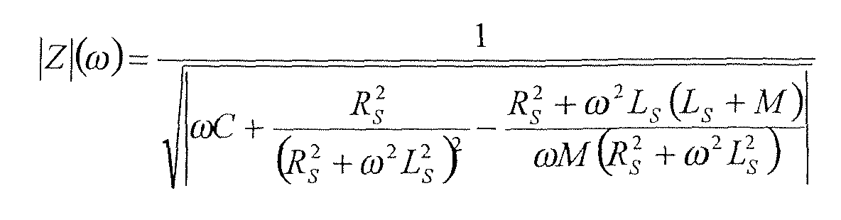
Figur 6H zeigt das Verhalten der Impedanz gemäß obiger Gleichung für verschiedene Sensorinduktivitätswerte.FIG. 6H shows the behavior of the impedance according to the above equation for different sensor inductance values.
Die Impedanz kann auch auf direktem Weg berechnet werden, ohne äquivalente
Parallelinduktivitäten und Parallelwiderstände zu berechnen. Dabei sind die
einzelnen Impedanzen von Sensor, Kapazität und Transformator gegeben durch:
Die Impedanz dieses Systems ist gegeben durch eine Parallelschaltung dieser drei
Impedanzen.

Die einfachste Methode zur Erzeugung einer Sinusschwingung besteht in der Entdärnpfung eines LC-Schwingkreises mit Hilfe eines Verstärkers. Die Figur 6I zeigt, wie eine Bohrkrone 610 mit einem Sensorelement 622 (Z S ) an einen LC-Oszillator 620, der vorzugsweise in oder an einer nicht dargestellten Antriebsmaschine für die Bohrkrone ausgebildet wird, über einen Koppeltransformator 641 gekoppelt werden kann. Die Parallelkapazität C P eines Parallelschwingkreises 652 kann auf der Bohrkrone selbst angeordnet sein.The simplest method for generating a sinusoidal oscillation consists in the de-saturation of an LC resonant circuit with the aid of an amplifier. FIG. 6I shows how a drill bit 610 with a sensor element 622 ( Z S ) can be coupled to an LC oscillator 620, which is preferably formed in or on a drive machine for the drill bit, not shown, via a coupling transformer 641. The parallel capacitance C P of a parallel resonant circuit 652 can be arranged on the drill bit itself.
Das in Figur 6J dargestellte, reduzierte Ersatzschaltbild zeigt, daß es sich
tatsächlich um einen klassischen Parallelschwingkreis 652 mit den Komponenten
L PP und C P handelt. Dabei ist L PP gegeben durch:
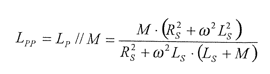
Auch ein Serienschwingkreis mit transformatorischem Übertrager läßt sich zur Signalmessung und -übertragung in einem erfindungsgemäßen Bohrsystem sinnvoll einsetzen. Dabei wird eine Kapazität auf der der Bohrkrone entgegengesetzten Seite des transformatorischen Übertragers in Reihe mit dem Transformator verschaltet. Dabei kann die Kapazität beispielsweise Teil einer Antriebsmaschine sein, die im Bohrsystem zum Antrieb der Bohrkrone Verwendung findet, oder auch Teil einer entsprechenden Meß- und/oder Auswerteschaltung bilden.A series resonant circuit with transformer transformer can be to Signal measurement and transmission in a drilling system according to the invention make sense. This is a capacity on the drill bit opposite side of the transformatory transformer in series with the Connected transformer. The capacity, for example, part of a Drive machine, which in the drilling system for driving the drill bit Use, or even part of a corresponding measuring and / or Form evaluation circuit.
Figur 7C stellt einen Serienschwingkreis 752 mit transformatorischem Übertrager dar, bei dem das T-Ersatzschaltbild 741' des transformatorischen Übertragers analog der Figur 6C anstelle des transformatorischen Übertragers eingesetzt worden ist.FIG. 7C shows a series resonant circuit 752 with transformer transformer in which the T-equivalent circuit diagram 741 'of the transformatory transformer used analogously to Figure 6C instead of the transformer transformer has been.
In erster Näherung können die Streuinduktivitäten des Übertragers vernachlässigt werden. Entsprechend wird in Figur 7D ein idealer, verlustfreier (RL=0) Koppeltransformator mit Koppelungsfaktor k=1 angenommen. Unter weiterer Vernachlässigung des Sensorwiderstands RS stehen die Sensorinduktivität L S und die Übertragerinduktivität M parallel zueinander. Nach Zusammenfassung dieser beiden Induktivitäten ergibt sich der reine Serienschwingkreis des reduzierten Ersatzschaltbilds der Figur 7D.As a first approximation, the stray inductances of the transformer can be neglected. Accordingly, in FIG. 7D, an ideal, lossless (R L = 0) coupling transformer with coupling factor k = 1 is assumed. With further neglect of the sensor resistance R S , the sensor inductance L S and the transformer inductance M are parallel to each other. After summarizing these two inductances, the pure series resonant circuit results in the reduced equivalent circuit of FIG. 7D.
Die Gesamtinduktivität L PP ist gegeben durch:
Die Resonanzfrequenz des Serienschwingkreises ist gegeben durch:
Durch Einsetzen ergibt sich:
Die Änderung der Resonanzfrequenz als Funktion der Änderung der
Sensorinduktivität, d.h. die Sensorempfindlichkeit, ist gegeben durch:
Dies bedeutet, daß die Änderung um so größer ist, je kleiner die Sensorinduktivität.This means that the smaller the change, the greater the change Sensor inductance.
Die Impedanz des RLC-Serienschwingkreises lautet allgemein:
Durch Einsetzen von LPP ergibt sich:
Wird die Streuinduktivitäten L σ nicht vernachlässigt, so ergibt sich als Gesamt-Serieninduktivität:
Die Streuinduktivität ist mit der Hauptinduktivität M über den Koppelungsfaktor k
(der nahe bei eins liegt) verknüpft:
Damit wird die Resonanzfrequenz:

Figur 7E zeigt den Frequenzverlauf der Impedanz, die als Belastung für den
Oszillator 720 aus der Schaltungsanordnung der Figur 7C resultiert, als Funktion
der Sensorinduktivität L S für verschiedene Werte der Sensorinduktivität im
Bereich 0,2 bis 1,1 mH. Ansonsten gelten die folgenden Werte:
Aus der Figur 7F ist ersichtlich, daß die Resonanzfrequenz des Systems stark von der Sensorinduktivität abhängt. From Figure 7F it can be seen that the resonant frequency of the system is greatly different from the sensor inductance depends.
Bei einer Änderung der Sensorinduktivität L S von beispielsweise 0,2 mH auf 1,1 mH ergibt sich ein Frequenzhub von etwa 4,5 kHz. In anderen Worten, die Resonanzfrequenz f res fällt bei Verwendung der gleichen Werte wie oben gemäß der in Figur 6G dargestellten Funktion von ca. 35 kHz auf 30,5 kHz. Dies zeigt, daß der Resonanzkreis nicht von der Übertragerinduktivität dominiert ist, sondern durchaus auf eine kleine Änderung der Sensorinduktivität L S empfindlich ist.When the sensor inductance L S is changed from, for example, 0.2 mH to 1.1 mH, a frequency deviation of approximately 4.5 kHz results. In other words, the resonant frequency f res falls from about 35 kHz to 30.5 kHz using the same values as above according to the function shown in FIG. 6G. This shows that the resonant circuit is not dominated by the transformer inductance, but is quite sensitive to a small change in the sensor inductance L S.
Verwendet man ein kapazitives Koppelungselement anstelle eines induktiven Kopplungselements beispielsweise zwischen einer Antriebsmaschine und der Bohrkrone, so vereinfacht sich das Ersatzschaltbild, denn es handelt sich hier bereits um einen reinen Serienschwingkreis. Die Resonanzfrequenz ist direkt abhängig von der Sensorinduktivität und die Impedanz hängt direkt von der Sensorimpedanz ab. Figur 8B zeigt einen derartigen Schwingkreis.Using a capacitive coupling element instead of an inductive Coupling element, for example, between a prime mover and the Drill bit, so simplifies the equivalent circuit, because it is here already a pure series resonant circuit. The resonance frequency is direct depending on the sensor inductance and the impedance depends directly on the Sensor impedance off. FIG. 8B shows such a resonant circuit.
Die Resonanzfrequenz ist gegeben durch:
Im Falle hoher Frequenzen (z.B. in der Größenordnung von 100kHz), ist das elektromagnetische System, das eine Sensorspule mit einem in der Nähe der Spule vorhandenen Armierungseisen bildet, äquivalent zu einem schwach gekoppelten Transformator. Durch Anlegen eines hochfrequenten Wechselstromes in der Sensorspule bilden sich Wirbelströme im Armierungseisen aus. Dieser zweite Strompfad im Armierungseisen kann wie die Sekundärspule eines Transformators behandelt werden, der über die Gegeninduktivität schwach an die Primärspule koppelt. Das System Sensorspule-Armierungseisen kann in ein äquivalentes Ersatzschaltbild umgewandelt werden, dessen Impedanz von der Gegeninduktivität M(x) zwischen Sensorspule und leitender Oberfläche des Armierungseisens und damit stark vom Abstand x zwischen Sensorspule und Eisenoberfläche abhängt. In the case of high frequencies (e.g., on the order of 100kHz), this is electromagnetic system that has a sensor coil with a near the Coil existing reinforcing iron forms, equivalent to a weak one coupled transformer. By applying a high-frequency alternating current In the sensor coil, eddy currents form in the reinforcing iron. This second rung in the rebar can be like the secondary coil of a Transformers are treated, the low on the mutual inductance Primary coil couples. The system sensor coil armouring iron can in a equivalent equivalent circuit to be converted whose impedance from the Mutual inductance M (x) between sensor coil and conductive surface of the Reinforcing iron and thus strongly from the distance x between the sensor coil and Iron surface depends.
Diese äquivalente Impedanz kann geschrieben werden als:

Dabei bedeuten:
- R eq :
- äquivalenter Serienwiderstand des Spulen-Target-Systems
- L eq :
- äquivalente Induktivität des Spulen-Target-Systems
- R 0:
- Verlustwiderstand der Sensorspule selbst
- L 0 :
- Induktivität der Sensorspule äquivalenter Verlustwiderstand des Strompfades im Eisen
- r(x):
- (Sekundärspule), hängt nur schwach vom Abstand ab äquivalente Induktivität des Strompfades im Eisen (Sekundärspule),
- l(x):
- hängt nur schwach vom Abstand ab Gegeninduktivität zwischen Sensorspule und Strompfad im Eisen, stark
- M(x):
- vom Abstand abhängig
- x:
- Abstand zwischen Sensorspule und Eisen
- R eq :
- equivalent series resistance of the coil-target system
- L eq :
- equivalent inductance of the coil-target system
- R 0 :
- Loss resistance of the sensor coil itself
- L 0 :
- Inductance of the sensor coil equivalent loss resistance of the current path in the iron
- r ( x ):
- (Secondary coil), depends only weakly on the distance from the equivalent inductance of the current path in the iron (secondary coil),
- l ( x ):
- depends only weakly on the distance Mutual inductance between sensor coil and current path in the iron, strong
- M ( x ):
- depending on the distance
- x :
- Distance between sensor coil and iron
Eine exakte Berechnung von M(x) ist nur in den seltensten Fällen analytisch
möglich. Die Figur 9C zeigt den allgemeinen Verlauf der Induktivität und des
äquivalenten Verlustwiderstandes als Funktion des Abstandes. Daraus ist
ersichtlich, daß der Verlustwiderstand R eq für größere Abstande fast hyperbolisch
verläuft, während er für kleine Werte bei einem gewissen maximalen Wert sättigt.
Dies liegt darin, daß für geringe Abstände x nicht mehr der gesamte Fluß die
Sensorspule durchdringt. Während die Änderung des Ersatzwiderstandes fast eine
Größenordnung ausmacht, beträgt die Änderung der Induktivität nur gerade 5-10%.
Dies bedeutet, daß die Auswerteschaltung vor allem auf den Realteil der äquivalenten Impedanz empfindlich sein sollte, da dieser größere Änderungen aufweist. Der Fachmann kennt verschiedene Möglichkeiten, um eine Meßschaltung für diesen Realteil zu realisieren.This means that the evaluation circuit is based primarily on the real part of equivalent impedance should be sensitive because of these larger changes having. The expert knows various ways to get one Realize measuring circuit for this real part.
Eine erste Möglichkeit ist die Verwendung eines LC-Oszillators mit konstantem Amplitudengang. Wirbelstromverluste durch die Nähe des Eisens bedämpfen diesen Oszillator, und die Amplitude der Oszillation nimmt ab. Nachteilig an diesem Ansatz ist, daß Nichtlinearitäten des Oszillators (z.B. als Funktion der Temperatur) selbst den Amplitudengang beeinflussen, und daß die Amplitudenänderung keine lineare Funktion des Abstandes x ist.A first option is to use a constant-frequency LC oscillator Amplitude response. Damp eddy current losses due to the proximity of the iron this oscillator, and the amplitude of the oscillation decreases. Disadvantageous In this approach, nonlinearities of the oscillator (e.g., as a function of the Temperature) itself affect the amplitude response, and that the Amplitude change is not a linear function of the distance x.
Eine Alternative liegt in der Verwendung eines LC-Parallelschwingkreises, der in Resonanz betrieben wird und mit einer hochfrequenten Konstantstromquelle angeregt wird.An alternative lies in the use of an LC parallel resonant circuit, which in Resonance is operated and with a high-frequency constant current source is stimulated.
In Resonanz ist die äquivalente Impedanz des Sensorspule-Armierungseisen-Systems
rein reell und indirekt proportional zum Ersatz-Verlustwiderstand des
Spulen-Eisen-Systems.
Prinzipiell kann jeder asymmetrische, induktive Wegaufnehmer als seine mit
Verlusten behaftete Spule dargestellt und mittels einer Brückenschaltung,
beispielsweise einer Wechselstrom-Viertelbrücke mit einer Konstantstromquelle,
gemessen werden. Da nur ein Viertel der Brücke seine Impedanz ändert, wird der
Ausgang der Brücke nicht linear sein. Die Ausgangsspannung der Brücke ändert
mit dem Abstand x in erster Ordnung wie:
Wird eine Wechselspannung E i an einen wie in der Figur 12 gezeigten, einfachen
Spannungsteiler angelegt, so wird die Spannung E 0 über die unbelastete Spule
gemessen:
Die Spannungsänderung δE 0 als Funktion der Impedanzänderung δZ der Spule
läßt sich wie folgt darstellen:
Der Zusammenhang zwischen δE 0 und δZ/Z ist nicht linear. Wird jedoch der
Serienwiderstand durch geeignete Wahl bzw. Ausbildung der als
Sensorvorrichtung fungierende Spule groß gegenüber der Impedanz der Spule
gemacht, so ergibt sich folgender linearer Zusammenhang:
Die Schlußfolgerung ist, daß ein Kompromiß zwischen Linearität (R/Z >> 1) und Sensitivität (R/Z <1). gefunden werden muß. Im Rahmen der vorliegenden Erfindung stellt die Linearität eine untergeordnete Rolle dar. Daher wird ein möglichst kleines Verhältnis R/Z bevorzugt.The conclusion is that a compromise between linearity ( R / Z >> 1) and sensitivity (R / Z <1). must be found. In the context of the present invention, the linearity plays a minor role. Therefore, the smallest possible ratio R / Z is preferred.
Die relative Spannungsänderung von E 0 ist gegeben durch:
Die Impedanzänderung der Spule mit Serienwiderstand RS und Gütefaktor Q als
Funktion des Abstandes zum Armierungseisen ist gegeben durch:
Dies bedeutet, daß die Impedanzänderung einerseits durch die Änderung des
äquivalenten Serienwiderstands, d.h. der Verluste, und andererseits durch die
Änderung der Induktivität der Spule durch die Nähe von permeablem Material
bewirkt wird. Der Beitrag der Verluste nimmt mit wachsender Spulengüte ab,
wogegen der Anteil der Induktivitätsänderung mit wachsendem Gütefaktor bis zu
einem Maximalwert zunimmt. Somit gilt für Q 2 >> 1:
Da sowohl Z als auch dZ komplex-wertig sind, ergibt sich ein Phasenwinkel in der
Ausgangsspannung:
Dieser Phasenwinkel kann mittels eines phasensensitiven Gleichrichters detektiert und kompensiert werden.This phase angle can be achieved by means of a phase-sensitive rectifier be detected and compensated.
Nicht nur die Impedanz Z = R + iωL kann als Meßgröße verwendet werden,
sondern auch der Q-Faktor:
Die Theorie der Oszillatoren ist nicht-linear und daher recht kompliziert. Analytische Ausdrücke wurden für vereinfachte Annahmen gefunden, sind hier aber nicht sehr hilfreich. Für die hiesige Erläuterung genügt es zu wissen, daß in einem Schwingkreis eine gewisse Schwingenergie gespeichert werden muß, und daß nur ein geringer Teil dieser oszillierenden Energie in den Verlusten der Spule (äquivalenter Serienwiderstand) absorbiert werden darf. Experimentell wurde gefunden, daß die gespeicherte Spitzenenergie mindestens doppelt so groß sein sollte als die Energie, die pro Schwingperiode dissipiert wird, um einen guten Oszillator zu bekommen.The theory of oscillators is non-linear and therefore quite complicated. Analytical terms were found for simplified assumptions, here are but not very helpful. For the explanation here it is sufficient to know that in a resonant circuit a certain oscillating energy must be stored, and that only a small part of this oscillating energy in the losses of the coil (equivalent series resistance) may be absorbed. Became experimental found that the stored peak energy at least twice should be considered a good energy dissipated per swing period To get oscillator.
Grundsätzlich gibt es zwei Arten von LC-Schwingkreisen, den Parallel- und den Serienschwingkreis. Figur 13A zeigt einen Serienschwingkreis, während Figur 13B einen Parallelschwingkreis zeigt. In beiden Fällen repräsentiert der Widerstand die Verluste der Spule.Basically, there are two types of LC resonant circuits, the parallel and the Series resonant circuit. FIG. 13A shows a series resonant circuit, while FIG. 13B shows a parallel resonant circuit. In both cases, the resistance represents the Losses of the coil.
Aus der Resonanzbedingung ergibt sich die Größe der Kapazität C:
In erster Ordnung ist die Güte Q dann gegeben durch:
Aus der experimentellen Feststellung kann geschlossen werden, daß die Güte
mindestens 4π betragen sollte.
Aus der Resonanzbedingung läßt sich schließen, daß eine Änderung des Q-Faktors
nur eine geringe Frequenzänderung bewirkt. Für kleine Änderungen von
Q und L ist die relative Frequenzänderung gegeben durch:
Daraus ist ersichtlich, daß die relative Induktivitätsänderung einen Faktor -1/2 beiträgt, da ω proportional zu 1/L ½ ist. Jedoch wird der Beitrag der Güte vernachlässigbar, je höher die Güte Q ist. Ist die Güte 10, so beträgt der Anteil nur noch 1%.It can be seen that the relative inductance change contributes a factor of -1/2 since ω is proportional to 1 / L ½ . However, the higher the quality Q, the less the contribution of quality becomes negligible. If the grade is 10, the share is only 1%.
Induktive Sensoren in Schwingkreisen bestehen typischerweise aus einer einzigen Spule. Aus diesem Grund ist die Abstandscharakteristik (die Induktivität L als Funktion des Abstandes des Armierungseisens) auch nicht linear. Aber da die Resonanzfrequenz proportional zu 1/(LC) ½ ist, zeigt die Frequenz-AbstandsCharakteristik ein lineareres Verhalten.Inductive sensors in resonant circuits typically consist of a single coil. For this reason, the distance characteristic (the inductance L as a function of the distance of the reinforcing iron) is also not linear. But since the resonance frequency is proportional to 1 / ( LC ) ½ , the frequency-spacing characteristic shows a more linear behavior.
Ein als erfindungsgemäße Meßschaltungskomponente bevorzugter Oszillator ist der relativ stabile PIERCE-Oszillator, wie er beispielsweise in "Systemtechnik induktiver Weg- und Kraftaufnehmer. Aufnehmer und Anschlußgeräte", von Horst R Loos, Erscheinungsdatum: 1992 ,ISBN: 3816905412 beschrieben wird. Er kann aus einer Transistorschaltung mit einer geerdeten Basis und einer kapazitiven Kopplung zwischen dem Emitter und dem Kollektor realisiert werden.A preferred as the invention measuring circuit component oscillator the relatively stable PIERCE oscillator, as used for example in "Systemtechnik inductive displacement and force transducer. Receivers and connecting devices ", by Horst R Loos, publication date: 1992, ISBN: 3816905412 is described. He can from a transistor circuit with a grounded base and a capacitive Coupling between the emitter and the collector can be realized.
Die Spannung eines solchen PIERCE-Oszillators ist in einem weiten Bereich
proportional zur Güte des Schwingkreises.
Eine weiterer Oszillator, der sich als erfindungsgemäße Meßschaltungskomponente besonders eignet, ist der (differentielle) Relaxationsoszillator, wie er beispielsweise in Passeraub, Philippe A.: "An integrated inductive proximity sensor", Konstanz, Hartung-Gorre, 1999, Series in microsystems; Vol. 1, Dissertation EPFL Lausanne, ISBN 3-89649-430-9 beschrieben wird. Figur 14 zeigt einen solchen Relaxationsoszillator.Another oscillator, which turns out to be inventive Is particularly suitable, the (differential) Relaxation oscillator, as described, for example, in Passeraub, Philippe A .: "An integrated inductive proximity sensor ", Konstanz, Hartung-Gorre, 1999, Series in microsystems; Vol. 1, Dissertation EPFL Lausanne, ISBN 3-89649-430-9 is described. Figure 14 shows such a relaxation oscillator.
Die Resonanzfrequenz des in Figur 14 gezeigten Relaxationsoszillators ist gegeben
durch die implizite Gleichung:

Ein Vorteil dieses Oszillators liegt darin, daß die Sensitivität über den Widerstand
R2 im Verstärker-Rückführungskreis und die Wahl der Induktivität L2 im
Verstärker-Rückführungskreis über weite Bereiche eingestellt werden kann. Mit
wachsender Induktivität L2 nimmt die Frequenz des Oszillators sehr steil zu und
erreicht (theoretisch) am Punkt:
Auch ein sogenannter Colpitts-Oszillator ist besonders zur Verwendung als erfindungsgemäße Meßschaltungskomponente geeignet. Bezüglich der Ausführung eines solchen Oszillators wird auf die einschlägige Literatur zur Oszillatoren verwiesen.Also, a so-called Colpitts oscillator is particularly suitable for use as Inventive Meßschaltungskomponente suitable. Regarding the execution such an oscillator is based on the relevant literature on oscillators directed.
Näheres über die Änderung der Impedanz einer Spule bei Näherung an ein Eisen kann in der einschlägigen Literatur, beispielsweise in J. Vine, Impedance of a Coil Placed near to a Conducting Sheet, 1963, gefunden werden. More about changing the impedance of a coil when approaching an iron can be found in the relevant literature, for example in J. Vine, Impedance of a Coil Placed near a Conducting Sheet, 1963, can be found.
Dort wird die Induktivität L und der Widerstand R einer Luftspule mit
Durchmesser a im Abstand d zu einer unendlich dicken leitenden Platte ist
gegeben durch:


Dabei bedeuten:
Im Grenzfall von sehr hohen Leitfähigkeiten oder Frequenzen vereinfacht sich
obige Formel zu:

In erster Näherung ändert sich der Realteil also nicht; einzig die Induktivität nimmt ab.In a first approximation, the real part does not change; only the inductance decreases.
Obwohl die bevorzugten und alternativen Ausführungsformen der Erfindung in dieser Beschreibung detailliert offenbart und beschrieben worden sind, ist für den Fachmann klar, daß verschiedene Änderungen bezüglich der Konfiguration, der Arbeitsweise und der Gestalt der Erfindung vorgenommen werden können, ohne den erfinderischen Gedanke sowie den Schutzbereich dieser zu verlassen. Insbesondere wird darauf hingewiesen, daß die jeweiligen Merkmale der Erfindung, einschließlich derjenigen, die lediglich in Kombination mit anderen Merkmalen der Erfindung offenbart sind, in beliebiger Konfiguration kombinierbar sind, außer denjenigen, die der Fachmann als offensichtlich unsinnig erkennt. Darüber hinaus zeigt die Verwendung des Singulars oder des Plurals lediglich auf eine Bevorzugung hin und ist nicht als Einschränkung zu interpretieren. Außer den Fällen, wo das Gegenteil explizit vermerkt ist, darf das Plural durch das Singular ersetzt werden und umgekehrt. Although the preferred and alternative embodiments of the invention in This description has been disclosed and described in detail, is for the It will be apparent to those skilled in the art that various changes in the configuration, the Operation and the shape of the invention can be made without to leave the inventive idea as well as the scope of protection. In particular, it should be noted that the respective characteristics of the Invention, including those that are used only in combination with others Characteristics of the invention are disclosed, can be combined in any configuration are, except those that the expert recognizes as obviously nonsensical. In addition, the use of the singular or the plural merely indicates a preference and is not to be interpreted as a limitation. Except In cases where the opposite is explicitly stated, the plural may be replaced by the Singular be replaced and vice versa.
- 0000
- BohrsystemDrilling System
- 0101
- Werkzeugaufnahmetool holder
- 1010
- Bohrkronedrill bit
- 1111
- HauptkronenteilMain crown part
- 1212
- abbauender Bereichdegrading area
- 1313
- abbauende Elementedegrading elements
- 1414
- Befestigungsteilattachment portion
- 1515
- abrasive Körnerabrasive grains
- 1616
- leitende Matrixconductive matrix
- 2020
- Sensorvorrichtungsensor device
- 2121
- HalbleitermagnetfeldsensorSemiconductor magnetic field sensor
- 21H21H
- Hall-SensorHall sensor
- 2222
- SpuleKitchen sink
- 22E22E
- Erregerspuleexcitation coil
- 22S22S
- Sensorspulesensor coil
- 2323
- Wirbelstrom-SensorelementEddy current sensor element
- 2424
- Jochyoke
- 2525
- elektrisch leitender Bereichelectrically conductive area
- 2626
- elektrisch isolierender Bereichelectrically insulating area
- 2727
- ohmsche Kontakteohmic contacts
- 2828
- Permanentmagnetpermanent magnet
- 2929
- Ferritkernferrite
- 3030
- Vergußmassesealing compound
- 3131
- Verschleißflächewearing surface
- 4040
- Leitungmanagement
- 4141
- transformatorischer Übertragertransformatory transformer
- 4242
- kapazitiver Übertragercapacitive transformer
- 4343
- Schleifringslip ring
- 4444
- Erdpotential (des Untergrunds)Ground potential (of the ground)
- 4545
- Kontaktflächecontact area
- 4646
- Stiftpen
- 5050
- Meß- und AuswertevorrichtungMeasuring and evaluation device
- 5151
- Oszillatoroscillator
- 5252
- Schwingkreisresonant circuit
- 5353
- Mikrokontrollermicrocontroller
- 6060
- Signalisierungsvorrichtungsignaling device
- 6161
- Anzeigevorrichtungdisplay device
- 7070
- Antriebsmaschineprime mover
- 7171
- Leistungselektronikpower electronics
- 7272
- Vorschubvorrichtungfeed device
- 7373
- Antriebvorrichtungdriving device
- 7474
- Werkzeugaufnahmetool holder
- 8181
- Armierungseisenrebar
- 8282
- induziertes Magnetfeldinduced magnetic field
Claims (48)
gekennzeichnet durch
eine Sensorvorrichtung, deren physikalische Kenngröße(n) vom elektromagnetischen Umfeld der Bohrkrone abhängt bzw. abhängen.drill bit
marked by
a sensor device whose physical characteristic (s) depends on the electromagnetic environment of the drill bit or depend.
dadurch gekennzeichnet, daß
die Sensorvorrichtung mindestens einen Magnetfeldsensor, insbesondere einen Halbleitermagnetfeldsensor, aufweist.Drill bit according to claim 1,
characterized in that
the sensor device has at least one magnetic field sensor, in particular a semiconductor magnetic field sensor.
dadurch gekennzeichnet, daß
die Bohrkrone einen Permanentmagneten oder einen Elektromagneten aufweist, dessen Magnetfeld vom elektromagnetischen Umfeld der Bohrkrone beeinflußt und von der Sensorvorrichtung erfaßt wird.Drill bit according to claim 2,
characterized in that
the drill bit has a permanent magnet or an electromagnet whose magnetic field is influenced by the electromagnetic environment of the drill bit and detected by the sensor device.
dadurch gekennzeichnet, daß
die Sensorvorrichtung mindestens eine Spule aufweist.Drill bit according to one of the preceding claims,
characterized in that
the sensor device has at least one coil.
dadurch gekennzeichnet, daß
die Sensorvorrichtung mindestens eine um die Rotationsachse der Bohrkrone gewickelte Spule sowie mindestens eine parallel zur Mantelfläche der Bohrkrone gewickelte Spule umfaßt, die in oder an der Bohrkrone angeordnet sind, wobei
die Bohrkrone aus nicht-ferromagnetischem Material, insbesondere aus nicht-ferromagnetischem Stahl, gefertigt ist.Drill bit according to claim 4,
characterized in that
the sensor device comprises at least one coil wound around the axis of rotation of the drill bit and at least one coil wound parallel to the lateral surface of the drill bit, which are arranged in or on the drill bit, wherein
the drill bit is made of non-ferromagnetic material, in particular of non-ferromagnetic steel.
dadurch gekennzeichnet, daß
die Bohrkrone aus einem Material mit schlechter Leitfähigkeit, insbesondere mit einer spezifischer Widerstand größer als 8×10⁻⁷ Ωm gefertigt ist.Drill bit according to claim 5,
characterized in that
the drill bit is made of a material with poor conductivity, in particular with a specific resistance greater than 8 × 10 -7 Ωm.
dadurch gekennzeichnet, daß
die Sensorvorrichtung mindestens eine um die Rotationsachse der Bohrkrone gewickelte Spule umfaßt, die in oder an der Bohrkrone angeordnet ist, wobei
die Bohrkrone ferromagnetisches Material enthält. Drill bit according to one of the preceding claims,
characterized in that
the sensor device comprises at least one coil wound around the axis of rotation of the drill bit, which is arranged in or on the drill bit, wherein
the drill bit contains ferromagnetic material.
dadurch gekennzeichnet, daß
die Sensorvorrichtung mindestens eine kapazitive Elektrode aufweist.Drill bit according to one of the preceding claims,
characterized in that
the sensor device has at least one capacitive electrode.
einem abtragenden Bereich,
dadurch gekennzeichnet, daß
die Sensorvorrichtung mindestens zwei elektrisch leitende Bereiche im abtragenden Bereich aufweist, die gegeneinander elektrisch isoliert sind.Drill bit according to one of the preceding claims, with
an erosive area,
characterized in that
the sensor device has at least two electrically conductive regions in the erosion region, which are electrically insulated from one another.
dadurch gekennzeichnet, daß
die elektrisch leitenden Bereiche derart im abtragenden Bereich angeordnet sind, daß sie auch bei einer Abnutzung des abtragenden Bereichs voneinander elektrisch isoliert bleiben.Drill bit according to claim 9,
characterized in that
the electrically conductive regions are arranged in the erosion region in such a way that they remain electrically insulated from one another even when the erosion region is worn away.
abtragenden Elementen
dadurch gekennzeichnet, daß
die Sensorvorrichtung mindestens zwei elektrisch leitende Elemente aufweist, die, elektrisch gegeneinander getrennt, in Höhe der abtragenden Elemente federnd oder beweglich gelagert sind.Drill bit according to one of the preceding claims, with
erosive elements
characterized in that
the sensor device has at least two electrically conductive elements, which, separated electrically, are mounted resiliently or movably in the height of the ablative elements.
gekennzeichnet durch
eine Kommunikationsvorrichtung, die Sensorsignale von der Sensorvorrichtung direkt oder indirekt erhält, und diese in serielle Signale umwandelt, die über eine einzige Signalleitung kommunizierbar sind.Drill bit according to one of the preceding claims,
marked by
a communication device that receives sensor signals from the sensor device directly or indirectly, and converts them into serial signals that are communicable via a single signal line.
gekennzeichnet durch
eine Meßvorrichtung, die Sensorsignale von der Sensorvorrichtung direkt oder indirekt erhält, und diese in Meßsignale umwandelt.Drill bit according to one of the preceding claims,
marked by
a measuring device which receives sensor signals from the sensor device directly or indirectly, and converts these into measurement signals.
dadurch gekennzeichnet, daß
die Umwandlung der Sensorsignale in Meßsignale eine Verstärkung und/oder eine Meßgrößenumwandlung umfaßt.Drill bit according to claim 13,
characterized in that
the conversion of the sensor signals into measurement signals comprises a gain and / or a measurement conversion.
gekennzeichnet durch
eine Spannungsversorgungsvorrichtung, die allein aus der rotatorischen Bewegung der Bohrkrone Energie gewinnt, die zur Stromversorgung der Kommunikationsvorrichtung und/oder der Meßvorrichtung und/oder der Sensorvorrichtung dient.Drill bit according to one of the preceding claims,
marked by
a power supply device that recovers energy solely from the rotary movement of the drill bit that serves to power the communication device and / or the measuring device and / or the sensor device.
gekennzeichnet durch
eine Bohrkrone nach einem der vorhergehenden Ansprüche, und
eine Auswerteeinrichtung, die den Zustand der Sensorvorrichtung hinsichtlich der Erkennung ferromagnetischen Materials in der Nähe der Bohrkrone auswertet und ein entsprechendes Signal ausgibt.Drilling System
marked by
a drill bit according to any one of the preceding claims, and
an evaluation device that evaluates the state of the sensor device with respect to the detection of ferromagnetic material in the vicinity of the drill bit and outputs a corresponding signal.
gekennzeichnet durch
eine Bohrkrone nach einem der vorhergehenden Ansprüche einschließlich Anspruch 4;
eine Erregerschaltung, welche die mindestens eine Spule derart erregt, daß Wirbelströme in dem die Spule umgebenden Material auftreten; und
eine Auswerteeinrichtung, die Wirbelstromverluste der Spule derart auswertet, daß die Beschaffenheit des der Spule benachbarten Materials ermittelt und ein entsprechendes Signal ausgegeben wird.Drilling System
marked by
a drill bit according to any one of the preceding claims including claim 4;
an energizing circuit which energizes the at least one coil such that eddy currents occur in the material surrounding the coil; and
an evaluation device which evaluates eddy current losses of the coil such that the nature of the material adjacent to the coil is determined and a corresponding signal is output.
dadurch gekennzeichnet, daß
dessen Bohrkrone mit einem Potential gegen Masse beaufschlagt und bei dem ein Leckstrom über die Bohrkrone und den umgebenden Untergrund gemessen werden.Drilling system for drilling a grounded object, in particular for mining a substrate,
characterized in that
whose drill bit is applied with a potential to ground and in which a leakage current across the drill bit and the surrounding ground are measured.
dadurch gekennzeichnet, daß
die Bohrkrone mit einer Wechselspannung oder Wechselstrom beaufschlagt und die von der Bohrkrone abgestrahlte Leistung gemessen wird.Drilling system for mining a subsurface,
characterized in that
The drill bit is subjected to an alternating voltage or alternating current and the power radiated by the drill bit is measured.
gekennzeichnet durch
eine Auswerteeinrichtung, die den gemessenen Leckstrom bzw. die gemessene Abstrahlleistung derart auswertet, daß ferromagnetisches Material in der Nähe der Bohrkrone erkannt und ein entsprechendes Signal generiert wird.Drilling system according to one of claims 18-19,
marked by
an evaluation device that evaluates the measured leakage current or the measured emission power such that ferromagnetic material is detected in the vicinity of the drill bit and a corresponding signal is generated.
gekennzeichnet durch
eine Signalisierungsvorrichtung, die in Abhängigkeit von dem erzeugten Signal
eine Anpassung eines oder mehreren Bohrparameters automatisch vornimmt; und/oder
einem Nutzer eine Anpassung eines oder mehreren Bohrparameters wahrnehmbar signalisiert; und/oder
einem Nutzer die Detektion eines Targets wahrnehmbar, insbesondere visuell und winkeltreu, signalisiert; und/oder
einem Nutzer einen Austausch der Bohrkrone wahrnehmbar signalisiert; und/oder
den Bohrvorgang automatisch abbricht.Drilling system according to one of claims 16, 17 or 20,
marked by
a signaling device in response to the generated signal
automatically adjusts one or more drilling parameters; and or
signaling a user perceptibly an adjustment of one or more drilling parameters; and or
a user, the detection of a target perceptible, in particular visually and angle faithfully, signals; and or
a user perceptibly signals an exchange of the drill bit; and or
automatically stops the drilling process.
dadurch gekennzeichnet, daß
die Anpassung eines oder mehreren Bohrparameters eine Anpassung
des Drehmoments;
der Schnittgeschwindigkeit;
der Wasserzufuhr;
der Anpreßkraft; und/oder
der Bohrleistung umfaßt.Drilling system according to claim 21,
characterized in that
the adaptation of one or more drilling parameters an adaptation
the torque;
the cutting speed;
the water supply;
the contact pressure; and or
the drilling power includes.
gekennzeichnet durch
Mittel zur Herstellung mindestens eines Signalübertragungspfads, vorzugsweise 2, 3 oder 4 Signalpfade, zur Bohrkrone.Drive device for a drill bit,
marked by
Means for producing at least one signal transmission path, preferably 2, 3 or 4 signal paths, to the drill bit.
gekennzeichnet durch
eine Antriebsvorrichtung gemäß Anspruch 23.A drilling system according to any one of claims 17-22,
marked by
a drive device according to claim 23.
gekennzeichnet durch
ein Vorsehen der Bohrkrone mit einer Sensorvorrichtung, deren physikalische Kenngröße(n) vom elektromagnetischen Umfeld der Bohrkrone abhängt bzw. abhängen.Method for determining a subsurface excavated by a drill bit,
marked by
a provision of the drill bit with a sensor device whose physical characteristic (s) depends on the electromagnetic environment of the drill bit or depend.
dadurch gekennzeichnet, daß
die Sensorvorrichtung mindestens einen Magnetfeldsensor, insbesondere einen Halbleitermagnetfeldsensor, aufweist. Method according to claim 25,
characterized in that
the sensor device has at least one magnetic field sensor, in particular a semiconductor magnetic field sensor.
dadurch gekennzeichnet, daß
die Bohrkrone einen Permanentmagneten oder einen Elektromagneten aufweist, dessen Magnetfeld vom elektromagnetischen Umfeld der Bohrkrone beeinflußt und von der Sensorvorrichtung erfaßt wird.Method according to claim 26,
characterized in that
the drill bit has a permanent magnet or an electromagnet whose magnetic field is influenced by the electromagnetic environment of the drill bit and detected by the sensor device.
dadurch gekennzeichnet, daß
die Sensorvorrichtung mindestens eine Spule aufweist.Method according to one of claims 25-27,
characterized in that
the sensor device has at least one coil.
dadurch gekennzeichnet, daß
die Sensorvorrichtung mindestens eine um die Rotationsachse der Bohrkrone gewickelte Spule sowie mindestens eine parallel zur Mantelfläche der Bohrkrone gewickelte Spule umfaßt, die in oder an der Bohrkrone angeordnet sind, wobei
die Bohrkrone aus nicht-ferromagnetischem Material, insbesondere aus nicht-ferromagnetischem Stahl, gefertigt ist.Method according to claim 28,
characterized in that
the sensor device comprises at least one coil wound around the axis of rotation of the drill bit and at least one coil wound parallel to the lateral surface of the drill bit, which are arranged in or on the drill bit, wherein
the drill bit is made of non-ferromagnetic material, in particular of non-ferromagnetic steel.
dadurch gekennzeichnet, daß
die Bohrkrone aus einem Material mit schlechter Leitfähigkeit, insbesondere mit einer spezifischer Widerstand größer als 8×10⁻⁷ Ωm gefertigt ist.Method according to claim 29,
characterized in that
the drill bit is made of a material with poor conductivity, in particular with a specific resistance greater than 8 × 10 -7 Ωm.
dadurch gekennzeichnet, daß
die Sensorvorrichtung mindestens eine um die Rotationsachse der Bohrkrone gewickelte Spule umfaßt, die in oder an der Bohrkrone angeordnet ist, wobei
die Bohrkrone ferromagnetisches Material enthält.Method according to one of claims 25-30,
characterized in that
the sensor device comprises at least one coil wound around the axis of rotation of the drill bit, which is arranged in or on the drill bit, wherein
the drill bit contains ferromagnetic material.
dadurch gekennzeichnet, daß
die Sensorvorrichtung mindestens eine kapazitive Elektrode aufweist.Method according to one of claims 25-31
characterized in that
the sensor device has at least one capacitive electrode.
die Bohrkrone einen abtragenden Bereich aufweist,
dadurch gekennzeichnet, daß
die Sensorvorrichtung mindestens zwei elektrisch leitende Bereiche im abtragenden Bereich aufweist, die gegeneinander elektrisch isoliert sind.The method of any of claims 25-32, wherein
the drill bit has a removal area,
characterized in that
the sensor device has at least two electrically conductive regions in the erosion region, which are electrically insulated from one another.
dadurch gekennzeichnet, daß
die elektrisch leitenden Bereiche derart im abtragenden Bereich angeordnet sind, daß sie auch bei einer Abnutzung des abtragenden Bereichs voneinander elektrisch isoliert bleiben.Method according to claim 33,
characterized in that
the electrically conductive regions are arranged in the erosion region in such a way that they remain electrically insulated from one another even when the erosion region is worn away.
die Bohrkrone abtragende Elemente aufweist,
dadurch gekennzeichnet, daß
die Sensorvorrichtung mindestens zwei elektrisch leitende Elemente aufweist, die, elektrisch gegeneinander getrennt, in Höhe der abtragenden Elemente federnd oder beweglich gelagert sind.The method of any of claims 25-34, wherein
the drill bit has erosion elements,
characterized in that
the sensor device has at least two electrically conductive elements, which, separated electrically, are mounted resiliently or movably in the height of the ablative elements.
gekennzeichnet durch
eine Umwandlung von direkt oder indirekt von der Sensorvorrichtung stammenden Sensorsignalen in serielle Signale, die über eine einzige Signalleitung kommunizierbar sind.Method according to one of claims 25-35
marked by
a conversion of sensor signals originating directly or indirectly from the sensor device into serial signals which can be communicated via a single signal line.
gekennzeichnet durch
eine Umwandlung von direkt oder indirekt von der Sensorvorrichtung stammenden Sensorsignalen in Meßsignale.A method according to any of claims 25-36.
marked by
a conversion of sensor signals originating directly or indirectly from the sensor device into measurement signals.
dadurch gekennzeichnet, daß
die Umwandlung der Sensorsignale in Meßsignale eine Verstärkung und/oder eine Meßgrößenumwandlung umfaßt.Method according to claim 37,
characterized in that
the conversion of the sensor signals into measurement signals comprises a gain and / or a measurement conversion.
gekennzeichnet durch
eine zur Umwandlung der Sensorsignale dienende Energiegewinnung allein aus der rotatorischen Bewegung der Bohrkrone.Method according to one of claims 25-38
marked by
one for the conversion of the sensor signals serving energy solely from the rotational movement of the drill bit.
gekennzeichnet durch
eine Auswertung des Zustands der Sensorvorrichtung hinsichtlich der Erkennung ferromagnetischen Materials in der Nähe der Bohrkrone; und
eine Ausgabe eines entsprechenden Signals.A method according to any one of claims 25-39
marked by
an evaluation of the state of the sensor device with respect to the detection of ferromagnetic material in the vicinity of the drill bit; and
an output of a corresponding signal.
gekennzeichnet durch
ein Versehen eines die Bohrkrone umfassenden Bohrsystems mit einer Erregerschaltung, welche die mindestens eine Spule derart erregt, daß Wirbelströme in dem die Spule umgebenden Material auftreten; und
ein Versehen des Bohrsystems mit einer Auswerteeinrichtung, die Wirbelstromverluste der Spule derart auswertet, daß die Beschaffenheit des der Spule benachbarten Materials ermittelt und ein entsprechendes Signal ausgegeben wird.Method according to one of claims 25-40 claims including claim 28,
marked by
providing a drilling system comprising a drilling system having an energizing circuit which energizes the at least one coil such that eddy currents occur in the material surrounding the coil; and
providing the drilling system with an evaluation device that evaluates eddy current losses of the coil such that the nature of the material adjacent to the coil is determined and a corresponding signal is output.
dadurch gekennzeichnet, daß
die Bohrkrone mit einem Potential gegen Masse beaufschlagt und bei dem ein Leckstrom über die Bohrkrone und den umgebenden Untergrund gemessen werden.Method of determining a grounded underground excavated by a drill bit,
characterized in that
the drill bit with a potential applied to ground and in which a leakage current across the drill bit and the surrounding ground are measured.
dadurch gekennzeichnet, daß
die Bohrkrone mit einer Wechselspannung oder Wechselstrom beaufschlagt und die von der Bohrkrone abgestrahlte Leistung gemessen wird.Method for determining a subsurface excavated by a drill bit,
characterized in that
The drill bit is subjected to an alternating voltage or alternating current and the power radiated by the drill bit is measured.
gekennzeichnet durch
eine Auswertung des gemessenen Leckstroms bzw. der gemessenen Abstrahlleistung derart, daß ferromagnetisches Material in der Nähe der Bohrkrone erkannt und ein entsprechendes Signal generiert wird.Method according to one of claims 42-43
marked by
an evaluation of the measured leakage current or the measured emission power such that ferromagnetic material is detected in the vicinity of the drill bit and a corresponding signal is generated.
gekennzeichnet durch
eine automatische Anpassung eines oder mehreren Bohrparameters; und/oder
eine einem Nutzer wahrnehmbare Signalisierung einer Anpassung eines oder mehreren Bohrparameters; und/oder
eine einem Nutzer wahrnehmbare, insbesondere visuelle und winkeltreue, Signalisierung einer Detektion eines Targets; und/oder
eine einem Nutzer wahrnehmbare Signalisierung eines Austausches der Bohrkrone; und/oder
eine automatische Abbrechung des Bohrvorgangs, wobei
die Anpassung, die Signalisierung und/oder die Abbrechung in Abhängigkeit von dem erzeugten Signal erfolgt. Method according to one of claims 40, 41 or 44,
marked by
an automatic adjustment of one or more drilling parameters; and or
a user-perceptible signaling of adaptation of one or more drilling parameters; and or
a perceptible to a user, in particular visual and angled, signaling a detection of a target; and or
a perceptible to a user signaling an exchange of the drill bit; and or
an automatic termination of the drilling process, wherein
the adaptation, the signaling and / or the cancellation takes place in dependence on the generated signal.
dadurch gekennzeichnet, daß
die Anpassung eines oder mehreren Bohrparameters eine Anpassung
des Drehmoments;
der Schnittgeschwindigkeit;
der Wasserzufuhr;
der Anpreßkraft; und/oder
der Bohrleistung umfaßt.Method according to claim 45,
characterized in that
the adaptation of one or more drilling parameters an adaptation
the torque;
the cutting speed;
the water supply;
the contact pressure; and or
the drilling power includes.
gekennzeichnet durch
ein Versehen der Antriebsvorrichtung mit Mitteln zur Herstellung mindestens eines Signalübertragungspfads, vorzugsweise 2, 3 oder 4 Signalpfade, zur Bohrkrone.Method for driving a drill bit by means of a drive device,
marked by
providing the drive device with means for producing at least one signal transmission path, preferably 2, 3 or 4 signal paths, to the drill bit.
gekennzeichnet durch
das Verfahren zur Bestimmung des Untergrunds einer Bohrkrone nach einem der Ansprüche 25-46; und
das Verfahren zum Antrieben einer Bohrkrone mittels einer Antriebsvorrichtung gemäß Anspruch 47.drilling
marked by
the method of determining the subsurface of a drill bit according to any of claims 25-46; and
the method for driving a drill bit by means of a drive device according to claim 47.
Applications Claiming Priority (2)
| Application Number | Priority Date | Filing Date | Title |
|---|---|---|---|
| DE102004020672A DE102004020672A1 (en) | 2004-04-28 | 2004-04-28 | Drill bit, drilling system and method for determining the electromagnetic environment of a drill bit |
| DE102004020672 | 2004-04-28 |
Publications (2)
| Publication Number | Publication Date |
|---|---|
| EP1591182A2 true EP1591182A2 (en) | 2005-11-02 |
| EP1591182A3 EP1591182A3 (en) | 2012-05-09 |
Family
ID=34939279
Family Applications (1)
| Application Number | Title | Priority Date | Filing Date |
|---|---|---|---|
| EP05102946A Withdrawn EP1591182A3 (en) | 2004-04-28 | 2005-04-14 | Drill bit, drilling system and method to determine the electromagnetical environment of a drill bit |
Country Status (2)
| Country | Link |
|---|---|
| EP (1) | EP1591182A3 (en) |
| DE (1) | DE102004020672A1 (en) |
Cited By (4)
| Publication number | Priority date | Publication date | Assignee | Title |
|---|---|---|---|---|
| DE102013205827A1 (en) * | 2013-04-03 | 2014-10-09 | Hilti Aktiengesellschaft | feeder |
| CN109715325A (en) * | 2016-09-23 | 2019-05-03 | 喜利得股份公司 | Coring bit |
| CN113758652A (en) * | 2021-09-03 | 2021-12-07 | 中国南方电网有限责任公司超高压输电公司广州局 | Converter transformer oil leakage detection method and device, computer equipment and storage medium |
| EP4140675A1 (en) * | 2021-08-25 | 2023-03-01 | Hilti Aktiengesellschaft | Rock drilling device and method for drilling reinforced rock |
Families Citing this family (3)
| Publication number | Priority date | Publication date | Assignee | Title |
|---|---|---|---|---|
| DE102014204833A1 (en) * | 2014-03-14 | 2015-09-17 | Werner Kluft | Device, machine tool and method for measuring and monitoring tools or workpieces |
| DE102015200617A1 (en) * | 2015-01-16 | 2016-07-21 | Zf Friedrichshafen Ag | Inductive position determination |
| CN112091301A (en) * | 2020-09-17 | 2020-12-18 | 中国航发贵州黎阳航空动力有限公司 | Cutter for milling machine to cut circle |
Citations (5)
| Publication number | Priority date | Publication date | Assignee | Title |
|---|---|---|---|---|
| FR2493510A1 (en) * | 1980-08-15 | 1982-05-07 | British Aerospace | ALIGNMENT DETECTION APPARATUS |
| DE3207747A1 (en) * | 1982-03-04 | 1983-09-08 | Schützeichel, Johannes, 5466 Neustadt | Device for monitoring drilling and sawing work in structures, especially prestressed concrete structures |
| EP0269562A2 (en) * | 1986-10-31 | 1988-06-01 | HILTI Aktiengesellschaft | Installation for the input of control data specific to a tool of a machine with an interchangeable tool |
| DE4027020A1 (en) * | 1990-08-27 | 1992-03-05 | Heinrich Liebig Gmbh | Detecting presence of metal reinforcement near bore in concrete - introducing probe generating magnetic or EM field and sensor measuring change in strength |
| EP1072903A1 (en) * | 1999-07-27 | 2001-01-31 | Oxford Instruments (Uk) Limited | Apparatus for nuclear magnetic resonance measuring while drilling a borehole |
Family Cites Families (9)
| Publication number | Priority date | Publication date | Assignee | Title |
|---|---|---|---|---|
| DE3324615A1 (en) * | 1982-11-27 | 1984-05-30 | Robert Bosch Gmbh, 7000 Stuttgart | Device for collecting drill cuttings |
| US4647853A (en) * | 1983-09-30 | 1987-03-03 | Teleco Oilfield Services Inc. | Mud turbine tachometer |
| DE4008304A1 (en) * | 1990-03-15 | 1991-09-19 | Hessabi Iradj | Cable conduit drilling device - has external guidance device with control magnet cooperating with magnet incorporated in drilling head |
| GB2288027B (en) * | 1994-03-31 | 1998-02-04 | Western Atlas Int Inc | Well logging tool |
| DE19833823A1 (en) * | 1998-07-28 | 2000-02-10 | Schluemer Heinz Dieter | Determining borehole center points or component edges on closed surfaces using four magnetic-Hall sensors, marking unit, optical device, electronic drive-evaluation units and magnet |
| AU2000265796A1 (en) * | 2000-08-08 | 2002-02-18 | Emtec Solutions Limited | Apparatus and method for telemetry |
| DE60231473D1 (en) * | 2001-01-12 | 2009-04-23 | Oxford Instr Superconductivity | METHOD AND DEVICE FOR GENERATING A MAGNETIC FIELD |
| ATE452280T1 (en) * | 2001-04-25 | 2010-01-15 | Halliburton Energy Serv Inc | METHOD AND SYSTEM AND TOOL FOR RESERVOIR ASSESSMENT AND WELLHOLE TESTING DURING DRILLING |
| DE10225518B4 (en) * | 2002-06-10 | 2004-07-08 | Rayonex Schwingungstechnik Gmbh | Method and device for controlling and determining the position of an instrument or device |
-
2004
- 2004-04-28 DE DE102004020672A patent/DE102004020672A1/en not_active Ceased
-
2005
- 2005-04-14 EP EP05102946A patent/EP1591182A3/en not_active Withdrawn
Patent Citations (5)
| Publication number | Priority date | Publication date | Assignee | Title |
|---|---|---|---|---|
| FR2493510A1 (en) * | 1980-08-15 | 1982-05-07 | British Aerospace | ALIGNMENT DETECTION APPARATUS |
| DE3207747A1 (en) * | 1982-03-04 | 1983-09-08 | Schützeichel, Johannes, 5466 Neustadt | Device for monitoring drilling and sawing work in structures, especially prestressed concrete structures |
| EP0269562A2 (en) * | 1986-10-31 | 1988-06-01 | HILTI Aktiengesellschaft | Installation for the input of control data specific to a tool of a machine with an interchangeable tool |
| DE4027020A1 (en) * | 1990-08-27 | 1992-03-05 | Heinrich Liebig Gmbh | Detecting presence of metal reinforcement near bore in concrete - introducing probe generating magnetic or EM field and sensor measuring change in strength |
| EP1072903A1 (en) * | 1999-07-27 | 2001-01-31 | Oxford Instruments (Uk) Limited | Apparatus for nuclear magnetic resonance measuring while drilling a borehole |
Cited By (7)
| Publication number | Priority date | Publication date | Assignee | Title |
|---|---|---|---|---|
| DE102013205827A1 (en) * | 2013-04-03 | 2014-10-09 | Hilti Aktiengesellschaft | feeder |
| CN109715325A (en) * | 2016-09-23 | 2019-05-03 | 喜利得股份公司 | Coring bit |
| CN109715325B (en) * | 2016-09-23 | 2020-08-11 | 喜利得股份公司 | Core bit |
| US11504779B2 (en) | 2016-09-23 | 2022-11-22 | Hilti Aktiengesellschaft | Core drill bit |
| EP4140675A1 (en) * | 2021-08-25 | 2023-03-01 | Hilti Aktiengesellschaft | Rock drilling device and method for drilling reinforced rock |
| CN113758652A (en) * | 2021-09-03 | 2021-12-07 | 中国南方电网有限责任公司超高压输电公司广州局 | Converter transformer oil leakage detection method and device, computer equipment and storage medium |
| CN113758652B (en) * | 2021-09-03 | 2023-05-30 | 中国南方电网有限责任公司超高压输电公司广州局 | Oil leakage detection method and device for converter transformer, computer equipment and storage medium |
Also Published As
| Publication number | Publication date |
|---|---|
| EP1591182A3 (en) | 2012-05-09 |
| DE102004020672A1 (en) | 2005-11-17 |
Similar Documents
| Publication | Publication Date | Title |
|---|---|---|
| EP1591182A2 (en) | Drill bit, drilling system and method to determine the electromagnetical environment of a drill bit | |
| DE60309678T2 (en) | PULSED TORQUE, POWER OR GENERAL MEASUREMENT WITH COIL AND MAGNETIC FIELD SENSOR (TANGENTIAL, SCOPE) | |
| EP1869505B1 (en) | Method for localising objects contained in a medium, and measuring appliance for carrying out said method | |
| EP3274527B1 (en) | Lock or window or door fitting | |
| DE3840532C2 (en) | ||
| DE102005002238A1 (en) | Sensor for locating metallic objects and measuring device with such a sensor | |
| DE3435812A1 (en) | DEVICE FOR MEASURING THE ROTATING SPEED OF A ROTATING ELEMENT | |
| DE60130890T2 (en) | Inductive sensor arrangement and method for detecting iron objects | |
| EP2555019B1 (en) | Inductive proximity sensor | |
| DE102006053023A1 (en) | Inductive proximity switch has transmission coil arrangement for producing alternating magnetic field, main transmission coil and coaxially surrounding compensating coil | |
| WO2013087283A2 (en) | Metal sensor | |
| EP0551606B1 (en) | Metal detector | |
| EP2224267A2 (en) | Operating method and coil assembly for a magnetic sensor for detection of metallic objects in a base | |
| DE102004031627A1 (en) | Method and device for the material-penetrating location of a measuring signal | |
| EP1538424A1 (en) | Microwave based position measurement system for an electrodynamic direct drive | |
| DE102007033745B4 (en) | Inductive speed detection | |
| DE102005019095A1 (en) | Measurement tape unit, e.g. used for detection and measurement of liquid level in borehole, detects and counts permeability variation markings in tape to measure length extended | |
| EP3108210B1 (en) | Sensor arrangement and method for determining a position and/or a change in the position of a measurement object | |
| EP2834601A1 (en) | Method and arrangement and sensor for determining the position of a component | |
| DE102006033961B4 (en) | Method and device for locating damage to a plastic pipe | |
| EP3314310B1 (en) | Device and method for detecting an article | |
| DE4027020C2 (en) | Method and device for determining the presence of metallic reinforcement elements in the interior of a concrete component | |
| DE102004006680B3 (en) | Sensor device for testing surfaces | |
| EP1742022A1 (en) | Position detection on a rod | |
| DE102007001821B4 (en) | Inductive proximity switch |
Legal Events
| Date | Code | Title | Description |
|---|---|---|---|
| PUAI | Public reference made under article 153(3) epc to a published international application that has entered the european phase |
Free format text: ORIGINAL CODE: 0009012 |
|
| AK | Designated contracting states |
Kind code of ref document: A2 Designated state(s): AT BE BG CH CY CZ DE DK EE ES FI FR GB GR HU IE IS IT LI LT LU MC NL PL PT RO SE SI SK TR |
|
| AX | Request for extension of the european patent |
Extension state: AL BA HR LV MK YU |
|
| PUAL | Search report despatched |
Free format text: ORIGINAL CODE: 0009013 |
|
| AK | Designated contracting states |
Kind code of ref document: A3 Designated state(s): AT BE BG CH CY CZ DE DK EE ES FI FR GB GR HU IE IS IT LI LT LU MC NL PL PT RO SE SI SK TR |
|
| AX | Request for extension of the european patent |
Extension state: AL BA HR LV MK YU |
|
| RIC1 | Information provided on ipc code assigned before grant |
Ipc: B23B 51/02 20060101AFI20120403BHEP |
|
| 17P | Request for examination filed |
Effective date: 20121109 |
|
| AKX | Designation fees paid |
Designated state(s): AT CH DE FR GB IT LI |
|
| 17Q | First examination report despatched |
Effective date: 20160928 |
|
| STAA | Information on the status of an ep patent application or granted ep patent |
Free format text: STATUS: EXAMINATION IS IN PROGRESS |
|
| STAA | Information on the status of an ep patent application or granted ep patent |
Free format text: STATUS: THE APPLICATION IS DEEMED TO BE WITHDRAWN |
|
| 18D | Application deemed to be withdrawn |
Effective date: 20170411 |