38 Turbofan & Turboprop Engines
Introduction
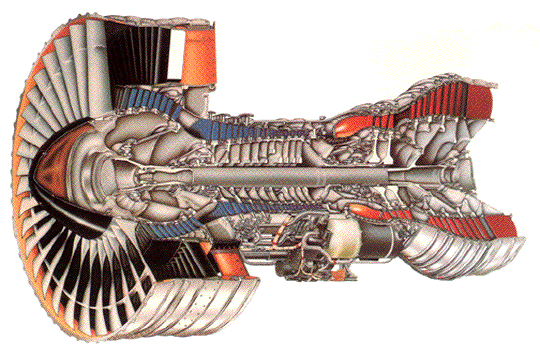
The turbofan and the turboprop are other variations of the primary gas turbine engine and have certain similarities in their design. They are both variations of the primary turbine engine, so their thermodynamics is based on the Brayton cycle. Similarly sized engines deliver similar power to the fan or propeller. The turbofan has a large fan stage on the front of the engine core, as shown in the cutaway below. The turbofan is a very efficient way of producing thrust, especially if it uses a high bypass ratio, i.e., most of the mass flow goes through the fan, and the fan creates most of the thrust. The turboprop uses a propeller driven by a power turbine, which is equivalent to a propulsion system with a very high bypass ratio.
The performance and analysis of turbofans and turboprops are similar in many ways. However, the propeller’s propulsive characteristics and aerodynamic limitations affect a turboprop’s operation as a system. Turboprops and turbofans have much better efficiency than turbojets in producing thrust for a given quantity of fuel. Turbofans are used on many commercial airliners, although turboprops may be used on smaller commuter aircraft. Turboprops are also used on some general aviation aircraft and military training aircraft. A turboshaft, which has the same essential core as a turboprop, can power helicopters and other machinery besides aircraft.
Learning Objectives
- Understand the functionality and characteristics of a turbofan engine and how it differs from a turbojet engine.
- Appreciate the concept of bypass ratio for a turbofan and how it contributes to its overall propulsive efficiency.
- Understand the characteristics of turboprop and turboshaft engines.
Design Characteristics of a Turbofan
The flow in a turbofan engine is split into two paths, as shown in the figure below:
- The flow through the engine’s core as in a turbojet engine.
- The fan produces the surrounding axial “bypass” flow.
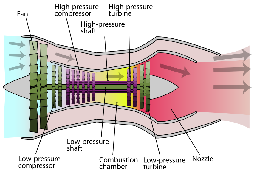
The fan spins much slower than the inner core of the engine, which contributes to its efficiency and reduces noise. A cowl surrounds the fan stage, guiding the airflow into the fan and the engine core. It is found that the thrust-producing efficiency of this type of engine is increased significantly by increasing the bypass ratio. Recall that the bypass ratio (BPR) is the area or mass flow through the fan divided by the area or mass flow through the core itself, i.e.,
(1) 
Like all engines, the thrust of a turbofan and its fuel consumption characteristics vary with flight conditions, i.e., with airspeed or Mach number and flight altitude. Such characteristics are determined from engine performance measurements supported by the mathematical modeling of the engine characteristics. However, remember that altitude is generally the density altitude, i.e., the altitude corresponding to the local ambient density.
Thrust Production
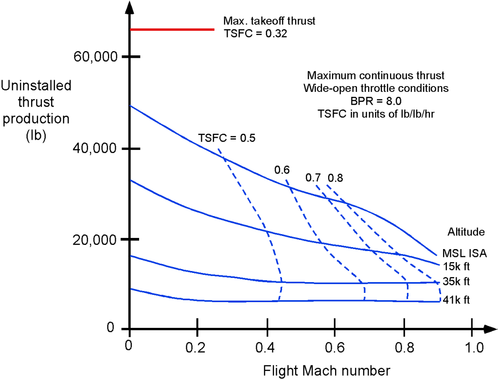
The thrust-producing capabilities of turbofan engines are found to be significantly affected by the airspeed  and the corresponding Mach number
  , and its thrust production decreases at higher airspeeds. The typical takeoff and climbing phase behavior is shown below, which will be at relatively low airspeeds below about 300 kts (flight Mach numbers < 0.5). Notice the reduction in thrust with increasing flight Mach number, a characteristic of this engine type. At higher Mach numbers, the thrust curves tend to flatten out at higher altitudes, but at lower altitudes, the thrust production diminishes quickly at transonic Mach numbers.
For design purposes, equations representing the characteristics of an engine are often helpful. During the takeoff and climb phase, the thrust for a turbofan engine is often approximated using the empirical equation
(2) 
The thrust from a turbofan can also be approximated using the equation
(3) 
where the values of the coefficients  and
and  depend not only on the engine type but also on its operational altitude. Notice that the variations of thrust with and are relatively large at lower altitudes. However, the assumption that thrust is almost constant is reasonable in the cruise range (say, between flight Mach numbers of 0.7 to 0.85 at higher flight altitudes). The same basic variation of thrust with altitude holds for turbofan engines, i.e.,
(4) 
where  is the thrust produced at MSL. Notice that
  in most cases, although the value can and will depend on the engine design.
Worked Example #1 – Thrust and power from a turbofan
The mass flow of air into the core of the engine is
![\[ \overbigdot{m}_{\rm core} = 20~\mbox{kg/s} \]](https://eaglepubs.erau.edu/app/uploads/quicklatex/quicklatex.com-868e8fe9f39779d647daa9a83d4473ed_l3.png "Rendered by QuickLaTeX.com")
and with a bypass ratio of 5:1, the mass flow into the fan will be
![\[ \overbigdot{m}_{\rm fan} = 5 \overbigdot{m}_{\rm core} = 100~\mbox{kg/s} \]](https://eaglepubs.erau.edu/app/uploads/quicklatex/quicklatex.com-75000a2bd935af3220dad7def5c89242_l3.png "Rendered by QuickLaTeX.com")
The mass flow rate of fuel is
![\[ \overbigdot{m}_f = 2~\mbox{kg/s} \]](https://eaglepubs.erau.edu/app/uploads/quicklatex/quicklatex.com-45c136f7942d6bba31efc3775d320114_l3.png "Rendered by QuickLaTeX.com")
Therefore, the thrust from the engine core is
![\[ T_{\rm core} = (\overbigdot{m}_{\rm core} + \overbigdot{m}_f) V_{\rm core} - \overbigdot{m}_{\rm core} V_{\infty} \]](https://eaglepubs.erau.edu/app/uploads/quicklatex/quicklatex.com-e7f5b75706510d9eb533246b2a64ce6e_l3.png "Rendered by QuickLaTeX.com")
And from the fan, the thrust is
![\[ T_{\rm fan} = \overbigdot{m}_{\rm fan} V_{\rm fan} - \overbigdot{m}_{\rm fan} V_{\infty} = \overbigdot{m}_{\rm fan} \left( V_{\rm fan} - V_{\infty} \right) = 5 \overbigdot{m}_{\rm core} \left( V_{\rm fan} - V_{\infty} \right) \]](https://eaglepubs.erau.edu/app/uploads/quicklatex/quicklatex.com-a6715a22d33c208340666230721e7b00_l3.png "Rendered by QuickLaTeX.com")
The total thrust is then.
![\[ T = T_{\rm core} + T_{\rm fan} \]](https://eaglepubs.erau.edu/app/uploads/quicklatex/quicklatex.com-5213526dbf708b1552a94219a3756a1e_l3.png "Rendered by QuickLaTeX.com")
In this case we are given that  = 20 kg/s,
  = 2 kg/s, and also that
  = 410 m/s,
  = 270 m/s, and = 200 m/s. Therefore, substituting the numbers gives
![\[ T_{\rm core} = (20.0 + 2.0 ) 410.0 - (20.0) 200 = 9,020 - 4,000 = 5.02~\mbox{kN} \]](https://eaglepubs.erau.edu/app/uploads/quicklatex/quicklatex.com-68b6ed7491f72ea749be7c82ccd50374_l3.png "Rendered by QuickLaTeX.com")
and
![\[ T_{\rm fan} = 5 (20.0) (270.0 - 200.0) = 7.0~\mbox{kN} \]](https://eaglepubs.erau.edu/app/uploads/quicklatex/quicklatex.com-c0c37b8f452f5fae52261703a113086c_l3.png "Rendered by QuickLaTeX.com")
The total thrust is
![\[ T = T_{\rm core} + T_{\rm fan} = 5.02 + 7.0 = 12.02~\mbox{kN} \]](https://eaglepubs.erau.edu/app/uploads/quicklatex/quicklatex.com-a98fc6769e1d43b2b41d230fac7c40af_l3.png "Rendered by QuickLaTeX.com")
The equivalent net power  that is developed is
![\[ P = T V_{\infty} = 12.02 \times 10^3 \times 200 = 2.4~\mbox{MW} \]](https://eaglepubs.erau.edu/app/uploads/quicklatex/quicklatex.com-606077ec2f44ecb7a1814b87ef52b844_l3.png "Rendered by QuickLaTeX.com")
Thrust Specific Fuel Consumption (TSFC)
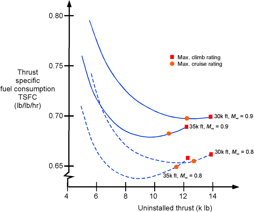
A representative thrust-specific fuel consumption (TSFC) map for a turbofan engine is shown in the figure below. For modeling purposes, the variation of the TSFC for a turbofan follows the relation
(5) 
where the values of  and
and  depend on the engine and the engine’s operational altitude. This latter equation has good validity in the cruise condition between flight Mach numbers of 0.7 to 0.85. The effect of altitude on the TSFC of a turbofan engine is fairly small (notice the greatly expanded scale), so the assumption that TSFC is constant is reasonable for use in a first-level aircraft flight performance analysis.
Design Characteristics of a Turboprop
A turboprop is a gas turboshaft engine at its core, as shown in the figure below. However, a low-pressure power turbine drives a propeller through a shaft, and only a small amount of jet thrust is produced, i.e., by design,  is relatively low, which also helps keep the noise lower. In fact, in this type of design, about 95% of the thrust comes from the propeller and only 5% from any residual jet thrust from the exhaust nozzle. The most common application of turboprop engines is for smaller, commuter-class aircraft. The turboprop engine is similar to the turboshaft, which is used extensively to supply power for helicopters. Examples of standard turboprop engines are the Pratt & Whitney PT6, used in many small commuter aircraft, and the Allison T56, which is used to power the Lockheed C-130 Hercules and the Lockheed P-3 Orion.
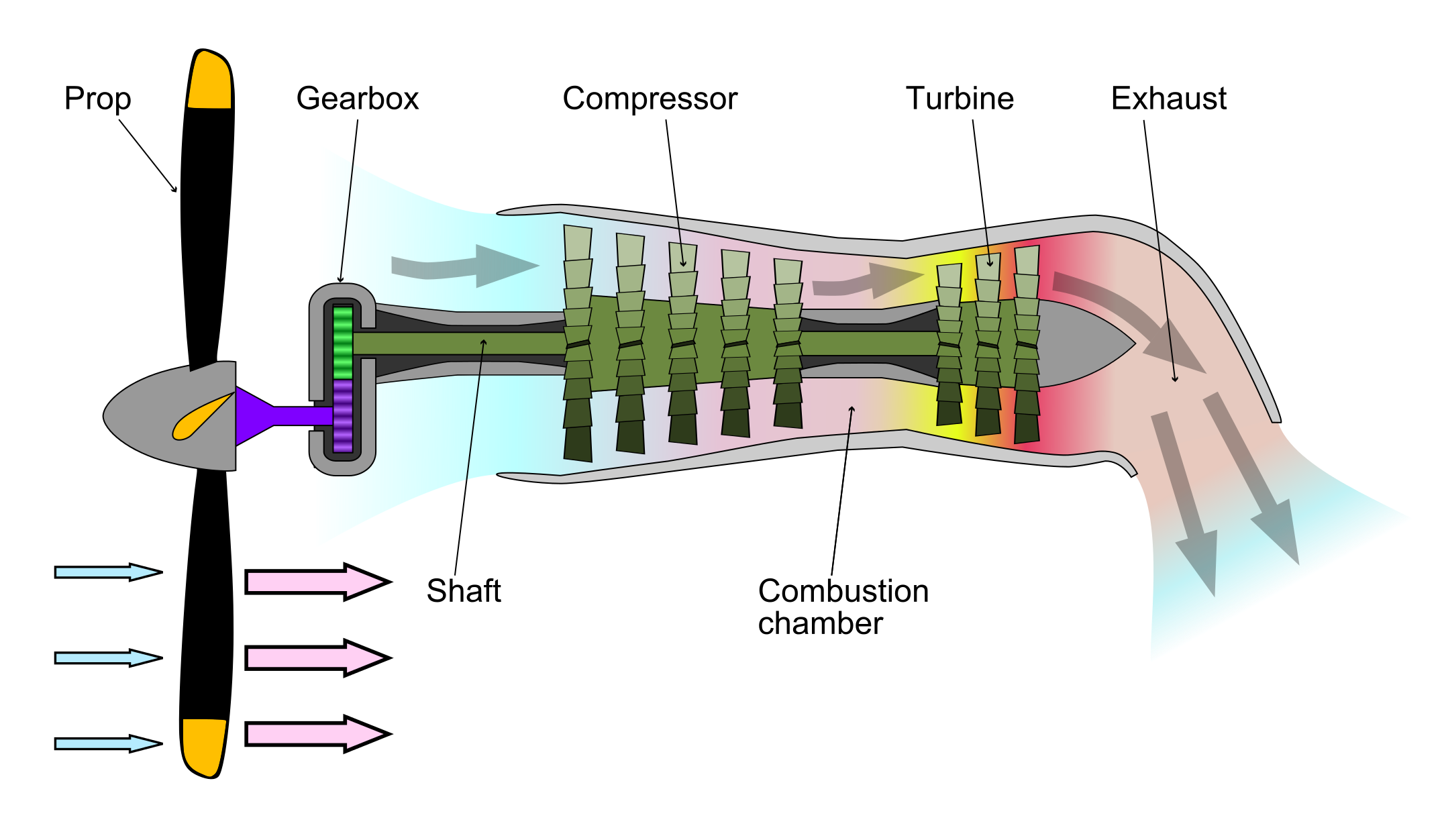
In the turboprop/shaft engine, the first three stages of the engine core are essentially the same for all gas turbine engines. However, in this case, the high-pressure turbine is followed by a low-pressure turbine, which powers the high-pressure compressor, and the low-pressure power turbine drives the propeller through a concentric shaft. The power turbine may be integral to the gas generator section, although most engines today have a free power turbine on a separate concentric shaft driving the propeller. This latter type of design enables the propeller to rotate freely, independently of the compressor’s rotational speed. In addition, because of the additional expansion in the low-pressure power turbine stage, the exhaust jet’s residual energy is low, and any jet thrust out of the exhaust nozzle is small, as previously discussed.
The propeller may be coupled to the power turbine through a speed reduction gearbox, which is needed to keep the propeller tip speeds less than the speed of sound. This approach maintains not only the overall propulsive efficiency but also lowers the noise from the propeller. This gearbox is mounted on the front of the engine behind the propeller. Because turboshaft engines are used to power high-performance airplanes, the propeller is always of the constant speed (variable pitch) type similar to that used with higher-powered reciprocating engines.
Regarding efficiency, the turboprop falls between the propeller/reciprocating engine combination and the turbofan or turbojet. Regarding airspeed capabilities, the maximum airspeed (or flight Mach number) for a turboprop-powered aircraft is limited by the propeller’s loss in efficiency when the blades begin to operate at higher helical Mach numbers. This characteristic results from compressibility losses and the onset of shock waves at the propellers’ tips. For this reason, turboprops tend to be limited to flight at lower airspeeds than turbojet or turbofan-powered aircraft and also to lower operational altitudes where the speed of sound is higher.
The performance of the turboprop can be analyzed using the basic conservation principles. The total thrust from the turboprop is  , where
  is the propeller thrust and
  is the jet thrust, and so the power from the turboprop is
(6) 
Defining the shaft power as the power available from the engine, then
(7) 
where  is the propulsive efficiency of the propeller and
  is the power produced by jet thrust. Defining equivalent shaft power
  as an overall power that includes jet thrust gives
(8) 
or
(9) 
The TSFC for the turboprop will be
(10) 
which is measured in terms of weight per hour per unit thrust, e.g., in units of lb hr lb or kg kN hr. Again, remember the anomaly of the SI system where mass (kg) is often used for TSFC instead of weight (N), and this difference should be accounted for in calculations, as needed. However, other definitions for TSFC for a turboprop can also be based on the net available power
  , the shaft power
  , or the “equivalent” shaft power , i.e.,
(11) 
The equivalent shaft power includes the small contribution from the jet thrust.
Both power and TSFC will vary with airspeed and altitude. For a turboprop, is approximately constant with up to a typical operational value of 0.6 or 0.65. The variation of with altitude follows the relationship
(12) 
where  is typical, although the exact value depends on the engine’s design. The specific fuel consumption of a turboprop is found to be relatively constant with both airspeed and altitude.
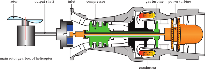
Turboshaft Engines
Turboshaft engines are very similar to turboprops in that they are designed to deliver power to a shaft, with only minor differences in their detailed design. Many engine manufacturers use a basic engine core customized as either a turboprop engine or a turboshaft engine. The differences in the various engines are usually confined to the compressor stages, which are optimized to reach the best pressure ratios for different operational flight scenarios and give the best power output and lowest specific fuel consumption.
Turboshaft engines are commonly used in helicopters, which drive the rotor(s) through a gearbox and transmission system, as shown in the figure below. The advantage of a turboshaft engine for a helicopter is that it is powerful and lightweight, i.e., it has a much better power-to-weight ratio than a piston engine. Turboshaft engines are used exclusively on helicopters except for smaller GA helicopters, where piston engines are usually a better alternative based on cost. Turboshaft engines are also used as auxiliary power units (they drive an electrical generator) on larger airplanes. On ships, turboshafts may be used for propulsion and may also be found on various other ground-based equipment.
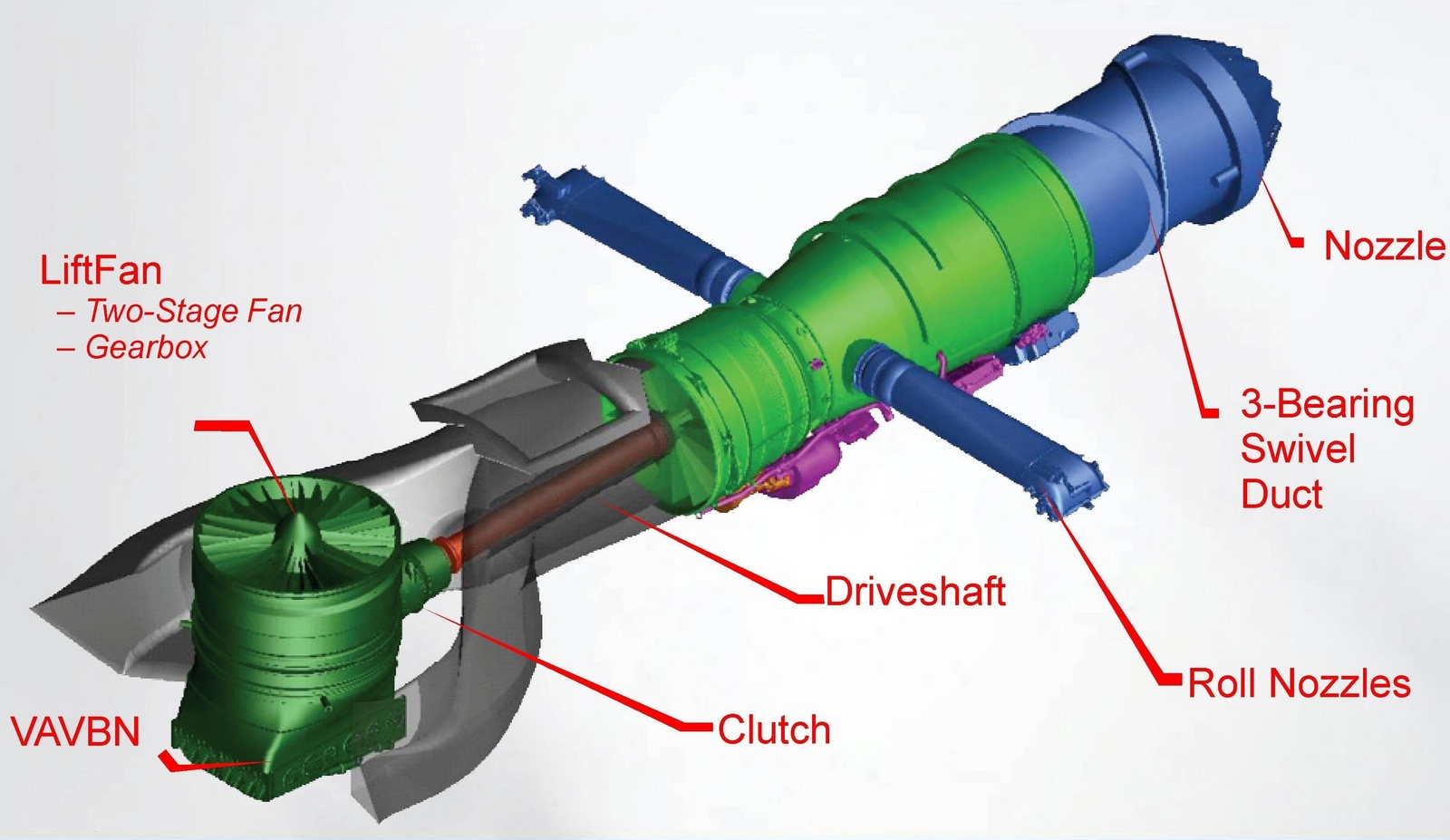
A unique use of the turboshaft engine is on the 29,000 hp (21,300 kW) Pratt & Whitney F135-PW-600 afterburning turbofan engine for the STOVL version of the F-35B, as shown in the figure below. In conventional (airplane) mode, the engine operates as a turbofan. However, when powering the lift fan for VTOL operation, it operates in turboshaft mode to send power through a shaft (i.e., like a turboprop). At the same time, the engine simultaneously continues to produce propulsive thrust as a turbofan.
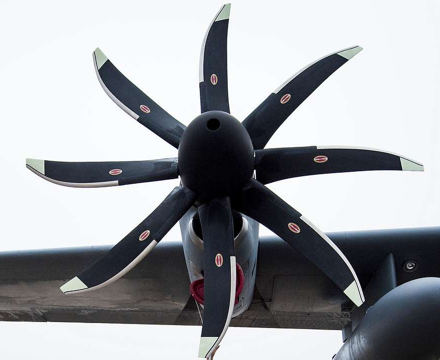
Open Rotor Design
The figure below shows a variation of the turboprop/turbofan concept known as an “Open-Rotor” concept, which engineers have explored for many decades. While the concept has been built and tested, including in-flight, it has not yet seen commercialization.
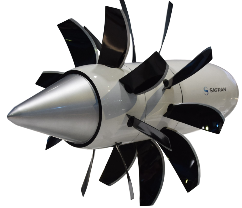
This type of design uses two contra-rotating high bypass fans to improve efficiency and reduce fuel burn. The concept also has a higher thrust-to-weight ratio than a turbofan. However, the rotor/prop combination has a significant shortcoming: it produces much higher noise levels than a turbofan. Today, reducing airplane noise is so important that an open rotor design faces many challenges from a noise perspective, i.e., from the standpoint of certification under US and European noise limits. Nevertheless, because of its high propulsive efficiency, the open rotor design will likely continue to receive attention from engineers.
How Many Engines?
One important design decision for an airplane, especially an airliner, is the number of engines to use. One benefit of using two or more engines is redundancy in that, in case of engine failure, the aircraft can still safely fly and make an emergency landing. Aircraft engines, however, are costly to purchase and operate, so airlines typically like to use twin-engine airliners. However, for some really large “Jumbo” aircraft, four engines may need to be used to have sufficient thrust and power to propel the aircraft, give it good climb performance, and ensure adequate one-engine inoperative performance. Twin-engine aircraft, however, are still subject to restrictions on long-distance, over-water operations under ICAO rules called ETOPS, which is an acronym for Extended-range Twin-engine Operations Performance Standards.
Aircraft with fewer engines will have lower fuel burn and better economics. For a jet engine, a good approximation of the thrust produced is
(13) 
where  is the pressure ratio at that altitude and
  is the corresponding absolute temperature ratio, which can be found from the ISA model.
Because jet engines will operate at or close to their rated thrust for much of the flight, a first-level approximation is to assume that their TSFC remains independent of power output. Of course, a better approximation is to calculate the actual fuel flow rate from the TSFC curve for the engine. By multiplying the TSFC by the thrust output, it will be apparent that the fuel flow rate  is a linear function of the thrust output. This relationship can be generalized as
(14) 
where  is the number of engines and the coefficients
  and
and  , depend on the characteristics of a particular engine.
It will be apparent that the total fuel flow will always be greater by approximately  for a multi-engine installation. Therefore, an aircraft design will generally try to use the fewest number of engines consistent with flight performance, the safety of flight, and other considerations. The recent retiral of the Boeing 747 and the A380 from many of the world’s airline fleets and the cessation of production of both models reflects an airline’s emphasis on costs.
Summary & Closure
Turbofans or turboprops are used on many aircraft types because of their high propulsive efficiency. Turboprops, however, are generally limited to smaller commuter aircraft or those that do not need to cruise at transonic flight conditions. A cowl around the large fan helps the turbofan perform better than a propeller at higher speeds and reduces noise. However, the propeller, too, has aerodynamic limits, including the loss of propulsive efficiency at high helical tip Mach numbers. At supersonic flight speeds, such as for a military fighter, turbojets are generally more suitable, but turbofans are increasingly used.
5-Question Self-Assessment Quickquiz
For Further Thought or Discussion
- Discuss why the propulsive efficiency of a turboprop system generally decreases at higher flight altitudes.
- Increasing the fan diameter of a turbofan engine can dramatically increase its thrust. Explain.
- Take a look at photographs of the large turbofan engines used on the Boeing 787. Why are there chevrons at the end of the bypass section of the engine?
- Research the Open Rotor concept and list its relative advantages and disadvantages compared to a turbofan.
- What are the advantages and disadvantages of a high bypass ratio in a turbofan engine?
- Explain the principle of reverse thrust and its significance for turbofan and turboprop engines.
- What factors determine the propulsive efficiency of a turboprop engine?
- Compare and contrast the fuel efficiency of turbofan and turboprop engines.
- How do the size and design of the propeller affect the performance of a turboprop engine?
- Discuss the factors that influence the selection of a turbofan or turboprop engine for a specific aircraft.
Other Useful Online Resources
To learn more about turbofans and turboprops, check out some of these online resources:
- A series of videos on how to build a jumbo-jet engine. See the playlist here.
- A tutorial on turbofan engines by CFM.
- A series of videos on the B-777 GE90 turbofan. See the playlist here.
- A great video tour of the Rolls Royce Engine factory, where they build the XWB engine for the Airbus A350.
- GE90 maximum thrust test!
- King Air turboprop demonstration – starting and varying blade pitch.
- Excellent video demonstration of a turboprop engine using a cutaway.
- Fascinating tour of a propeller overhaul facility!
- Video on how a turboshaft engine is used to power a helicopter.
- First tests of a new open rotor propulsion system.
- Airbus is getting ready to test an open-rotor design on an A-380.
