airframe
(redirected from airframes)Also found in: Dictionary, Thesaurus.
airframe
[′er‚frām]Airframe
The structural backbone of an aircraft that balances the internal and external loads acting upon the craft. These loads consist of internal mass inertia forces (equipment, payload, stores, fuel, and so forth), flight forces (propulsion thrust, lift, drag, maneuver, wind gusts, and so forth), and ground forces (taxi, landing, and so forth).
The strength capability of the airframe must be predictable to ensure that these applied loads can be withstood with an adequate margin of safety throughout the life of the airplane. In addition to strength, the airframe requires structural stiffness to prevent excessive deformation under load and to provide a satisfactory natural frequency of the structure (the number of times per second the structure will vibrate when a load is suddenly imposed or changed). The aerodynamic loads on the airframe can oscillate in magnitude under some circumstances, and if these oscillations are near the same rate as the natural frequency of the structure, runaway deflections (called flutter) and failure can occur. Consequently, adequate structural stiffness is needed to provide a natural frequency far above the danger range. See Aeroelasticity
The overall airframe structure is made up of a number of separate components, each of which performs discrete individual functions. The fuselage provides the accommodations of crew, passengers, cargo, fuel, and environmental control systems. The empennage consists of the vertical and horizontal stabilizers, which are used, respectively, for turning and pitching flight control. The wing passing through the air provides lift to the aircraft. Its related control devices, leading-edge slats and trailing-edge flaps, are used to increase this lift at slow airspeeds, such as during landing and takeoff, to prevent stalling and loss of lift. The ailerons increase lift on one side of the wing and reduce lift on the other in order to roll the airplane about its fore-and-aft axis. See Fuselage, Wing
Performance requirements (range, payload, speed, altitude, landing and takeoff distance, and so forth) dictate that the airframe be designed and constructed so as to minimize its weight. All the airframe material must be arranged and sized so that it is utilized as near its capacity as possible, and so that the paths between applied loads and their reactions are as direct and as short as possible. The accomplishment of these goals, however, is compromised by constraints such as maintenance of the aerodynamic shape, the location of equipment, minimum sizes or thicknesses that are practical to manufacture, and structural stability, among others.
To maintain structural efficiency (minimum weight), the material that forms the aerodynamic envelope of the airplane is also utilized as a primary load-carrying member of the airframe. For example, the thin sheets that are commonly used for outer fuselage skins are very efficient in carrying in-plane loads like tension and shear when they are stabilized (prevented from moving or deflecting out of the way when loads are applied). This structural support is provided by circumferential frames and longitudinal primary members called longerons. The compression loads are also carried in the longerons and the thin skins when they are additionally stabilized by multiple secondary longitudinal stiffeners that are normally located between the frames. Illustration a shows a typical fuselage primary load path structure indicating the frames and longerons. This skeleton will be covered by thin skins.
)
Various analytical techniques may be used to determine the internal stress levels for each of the airframe components. The most common analytical methods use the technique of reducing these highly complex structural arrangements into a group of well-defined simple structures known as finite elements. This simplification allows the load distribution to be solved by a series of algebraic equations.
The finite element model used for the determination of the internal load distribution must support various structural objectives that include the analysis of strength, stiffness, and damage tolerance characteristics of the aircraft. In order to accomplish these objectives the finite element model must represent the vehicle configuration in sufficient detail to define adequately the basic characteristics of the local structural load paths and provide for application of all external loading parameters. Illustration b shows the complete finite element model of an airframe. The many varied loading parameters include airloads, structural weight, engine thrust, landing gear reactions, fuel tanks, cargo, and passengers. Environmental factors such as cabin pressure and structural heating must also be considered.
airframe
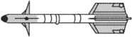
ii. The assembled structural components of a missile but excluding its propulsion system, controls, electronic equipment, and payload.
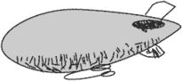
iii. The framework, envelope, and cabin of an airship.