I'm working with a 28BYJ-48 step motor. Instead of ordering the ULN2003 Motor Driver board, I ordered a ULN2003 Darlington IC. After looking at tons of pages and videos, I see most of the tutorials use the motor driver board. I've ordered it and am waiting for it to show up. In the meantime, I thought I'd try replicating the motor driver board if it turns out that I have the parts on hand.
The capacitors used in that manner are commonly called decoupling capacitors or bypass capacitors. The following is taken from the Wikipedia but the same general description likely can be found anywhere using the mentioned naming conventions.
"A decoupling capacitor is a capacitor used to decouple one part of an electrical network (circuit) from another. Noise caused by other circuit elements is shunted through the capacitor, reducing the effect it has on the rest of the circuit. An alternative name is bypass capacitor as it is used to bypass the power supply or other high impedance component of a circuit".
They are your friends. Embellish them and treat them well.
Mark_T and Ron_Blain, By giving me the correct terminology there, you've helped me to fish for myself. Thank you! I will be spending time "becoming one" with decoupling capacitors!
wvmarle:
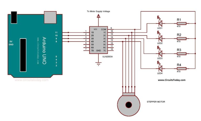
Those LEDs may of course be omitted, you're not trying to run a light show but a motor.
Funny! They're kind of like pretty training wheels, giving a level of comfort while I'm in the early stages of figuring out what I'm doing. Will remove them shortly. Thanks!
raschemmel:
Were you planning on powering the motor with the Arduino 5V regulator ?
No. Everything I've read tells me it's bad practice to drive the motor using the Arduino's 5V. I connected up the DC Power Supply to it for now, since I don't have an appropriate battery pack. But, thank you for asking about it.
The 28BYJ-48 that it works well when the Arduino is powered over USB and the motor is powered through the 5V pin. It takes some 300 mA typically.
Wiring it like that is OK for testing, not a good idea for a more permanent installation. Then you better take a regulated 5V supply, powering the Arduino through its 5V pin and the motor directly.
Now if you want to improve on the ULN2003 (which is an old design - using lossy darlington transistors, dropping up to 2V leaving a mere 3V for the motor!) consider replacing it with an array of MOSFETs. There also exist drop-in MOSFET based replacements for the ULN2003 but they're not that easy to find unfortunately. Or consider to use this stepper in bipolar mode (using 4-wire connection) with a regular stepper driver. That also makes control on the Arduino side easier.