advertisement

Technical Service Instructions
SI-5EW0B
FD-4403
Front derailleur
General Safety Information
WARNING
• Obtain and read the service instructions carefully prior to installing the parts. Loose, worn, or damaged parts may cause injury to the rider.
We strongly recommend only using genuine
Shimano replacement parts.
• Be careful not to let the cuffs of your clothes get caught in the chain while riding, otherwise you may fall off the bicycle.
• Read these Technical Service Instructions carefully, and keep them in a safe place for later reference.
Note
• If gear shifting operations cannot be carried out smoothly, clean the derailleur and lubricate all moving parts.
• If the amount of looseness in the links is so great that adjustment is not possible, you should replace the derailleur.
• When the chain is in the position shown in the illustration, the chain may contact the front chainrings or front derailleur and generate noise.
If the noise is a problem, shift the chain onto the next-larger rear sprocket or the one after.
Front chainrings
Rear sprockets
• If attaching the FD-4403 (brazed-on type) to a seat tube with a thickness of more than 31.8 mm, the derailleur may come into contact with the seat tube and interfere with normal gear shifting performance.
• For smooth operation, use the specified outer casing and the bottom bracket cable guide.
• Grease the inner cable and the inside of the outer casing before use to ensure that they slide properly.
• This front derailleur is for triple front chainwheel use only. It cannot be used with the double front chainwheel, as the shifting points do not match.
• For the chain, be sure to use only the Shimano narrow type chain. The wide type chain cannot be used.
• Parts are not guaranteed against natural wear or deterioration resulting from normal use.
• For maximum performance we highly recommend
Shimano lubricants and maintenance products.
• For any questions regarding methods of installation, adjustment, maintenance or operation, please contact a professional bicycle dealer.
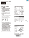
In order to realize the best performance, we recommend that the following combination be used.
Series
Shifting lever
Outer casing
Gears
Front derailleur
Front chainwheel
Bottom bracket
Rear derailleur
Freehub
Cassette sprocket
Chain
Bottom bracket cable guide
TIAGRA
ST-4400 / ST-R600
SL-R440
SP40
27
FD-4403
FC-4404
BB-ES51 / BB-ES30
RD-4400-GS
FH-4400
CS-HG50-9
CN-HG53
SM-SP17
Specifications
Type
Front chainwheel tooth difference
Min. difference between top and intermediate
Front derailleur installation band diameter
Chainstay angle (
C
)
Chain line
Band type / Brazed on type
22 teeth or less
10T
S (28.6mm), M (31.8mm)
63° - 66°
45mm
Chainstay angle
Installation of the front derailleur
Adjust and then install the front derailleur as shown in the illustration. Do not remove the Pro-Set alignment block at this time.
Pro-Set alignment block
Gear teeth should come within this range
Pro-Set gauge
1mm
3mm
The level section of the chain guide outer plate should be directly above and parallel to the largest chainring.
Secure using a 5mm Allen key.
Tightening torque:
5 - 7 N·m
{44 - 60 in. lbs.}
Chainwheel
(largest chainring)
Chain guide t
SIS adjustment
Be sure to follow the sequence described below.
1. Low adjustment
First remove the Pro-Set alignment block. Next, set so that the clearance between the chain guide inner plate and the chain is 0 - 0.5mm.
Chain position
Largest sprocket
Smallest chainring
Pro-Set alignment block
Note: There are 2 derailleur positions for the intermediate chainring. When making the cable adjustment, make sure that the derailleur is in the inner side (toward small chainring) of the two positions. Locate the derailleur to this position by shifting from the largest to the intermediate chainring (recommended) or by shifting from the small to the intermediate chainring, then gently press lever (b) until a small click is felt (to position the derailleur to the inner side of the intermediate chainring).
Adjust the cable tension by using the outer adjustment barrel so that the clearance between the chain guide inner plate and the chain is 0 -
0.5 mm.
B
B A
Low adjustment screw
Chain guide inner plate
Chain
A
2. Connection and securing of cable
While pulling the inner cable, tighten the wire fixing bolt with a 5 mm allen key to secure the cable.
Tightening torque:
5 - 7 N·m
{44 - 60 in. lbs.}
Pull
After taking up the initial slack in the cable, re-secure to the front derailleur as shown in the illustration.
3. Top adjustment
Set so that the clearance between the chain guide outer plate and the chain is 0-0.5 mm.
Chain position
Smallest sprocket
Largest chainring
B
B A
Top adjustment screw
A
Chain guide inner plate
Chain
4. Cable adjustment using the intermediate chainring
When making the cable adjustment, place the chain on the largest sprocket for the rear and the middle chainring for the front.
Chain position
Largest sprocket
Intermediate chainring
B A
Outer casing adjustment bolt
Front shifting (ST-4400)
Chain guide inner plate
B
Chain
A
Lever [
Lever [
Lever [
From large chainring to small chainring
Lever
[
From small chainring to large chainring
5. Troubleshooting chart
After completion of steps 1 - 4, move the shifting lever to check the shifting. (This also applies if shifting becomes difficult during use.)
If the chain falls to the crank side
If shifting is difficult from the intermediate chainring to the largest chainring
If shifting is difficult from the intermediate chainring to the smallest chainring
If there is interference between the chain and the front derailleur inner plate at the largest chainring
If there is interference between the chain and the front derailleur outer plate at the largest chainring
If the intermediate chainring is skipped when shifting from the largest chainring
If there is interference between the chain and front derailleur inner plate when the rear sprocket is shifted to the largest sprocket when the chainwheel is at the intermediate chainring position.
If the chain falls to the bottom bracket side.
Tighten the top adjustment screw clockwise (about 1/4 turn).
Loosen the top adjustment screw counterclockwise (about 1/8 turn).
Loosen the low adjustment screw counterclockwise (about 1/4 turn).
Tighten the top adjustment screw clockwise (about 1/8 turn).
Loosen the top adjustment screw counterclockwise (about 1/8 turn).
Loosen the outer casing adjustment barrel counterclockwise (1 or 2 turns).
Tighten the outer casing adjustment barrel clockwise (1 or 2 turns).
Tighten the low adjustment screw clockwise (about 1/2 turn).
Be sure to read these service instructions in conjunction with the service instructions for the ST-4400 / R600, SL-R440 before use.
One Holland, Irvine, California 92618, U.S.A. Phone: +1-949-951-5003
Industrieweg 24, 8071 CT Nunspeet, The Netherlands Phone: +31-341-272222 3-77 Oimatsu-cho, Sakai, Osaka 590-8577, Japan
Please note: specifications are subject to change for improvement without notice. (English)
© Jul. 2004 by Shimano Inc. XBC SZK Printed in Japan.
t
advertisement
* Your assessment is very important for improving the workof artificial intelligence, which forms the content of this project
Related manuals
advertisement