Fostex FD-8 Service Manual
Digital multitracker
Hide thumbs
Also See for FD-8:
- Owner's manual (121 pages) ,
- Quick operation manual (28 pages) ,
- Supplement owner's manual (2 pages)
Table of Contents
Advertisement
Advertisement
Table of Contents

Related Manuals for Fostex FD-8


Summary of Contents for Fostex FD-8
- Page 1 Service Manual Model FD-8 DIGITAL MULTITRACKER...
-
Page 2: Safety Instructions
CAUTION RISK OF ELECTRIC SHOCK DO NOT OPEN CAUTION: TO REDUCE THE RISK OF ELECTRIC SHOCK, DO NOT REMOVE COVER (OR BACK). NO USER-SERVICEABLE PARTS INSIDE. REFER SERVICING TO QUALIFIED SERVICE PERSONNEL. The lightening flash with arrowhead symbol, within an equilateral triangle, is intended to alert the user to the presence of uninsulated “dangerous voltage”... -
Page 3: Table Of Contents
Service mode, error code list, exploded view, PCB assembly, parts list and circuit diagrams are given in this manual to assist the service technician in maintaining the Model FD-8. The following accessories are supplied with FD-8 as the standard accessories. -
Page 4: Specifications
FD-8 1. SPECIFICATIONS RECORD & REPRODUCE Recording Medium Standard Sampling Frequency Quantization Emphasis Compression / Expansion Method Recording Time (mono track min.) MASTERING mode NORMAL mode Number of Tracks Number of recording tracks Number of simultaneous recording tracks Number of simultaneous playback tracks... - Page 5 80 ~ 20 kHz +1, -2 dB (AUX RTN: -20 dBV, at 20 mW / output) +15 dB ± 3 dB at “+15” position -15 dB ± 3 dB at “-15” position +15 dB ± 3 dB at “+15” position -15 dB ± 3 dB at “-15” position FD-8...
- Page 6 FD-8 ELECTRICAL (continued) S / N INPUT INPUT INPUT 8 Residual Noise Distortion INPUT INPUT -40 dBV AUX RTN -10 dBV -10 dBV Crosstalk Click Noise Power on / off Other switching MIDI Controlling • RECORDER SECTION Frequency Response Full Scale Output Level (Ref: -12 dB)
-
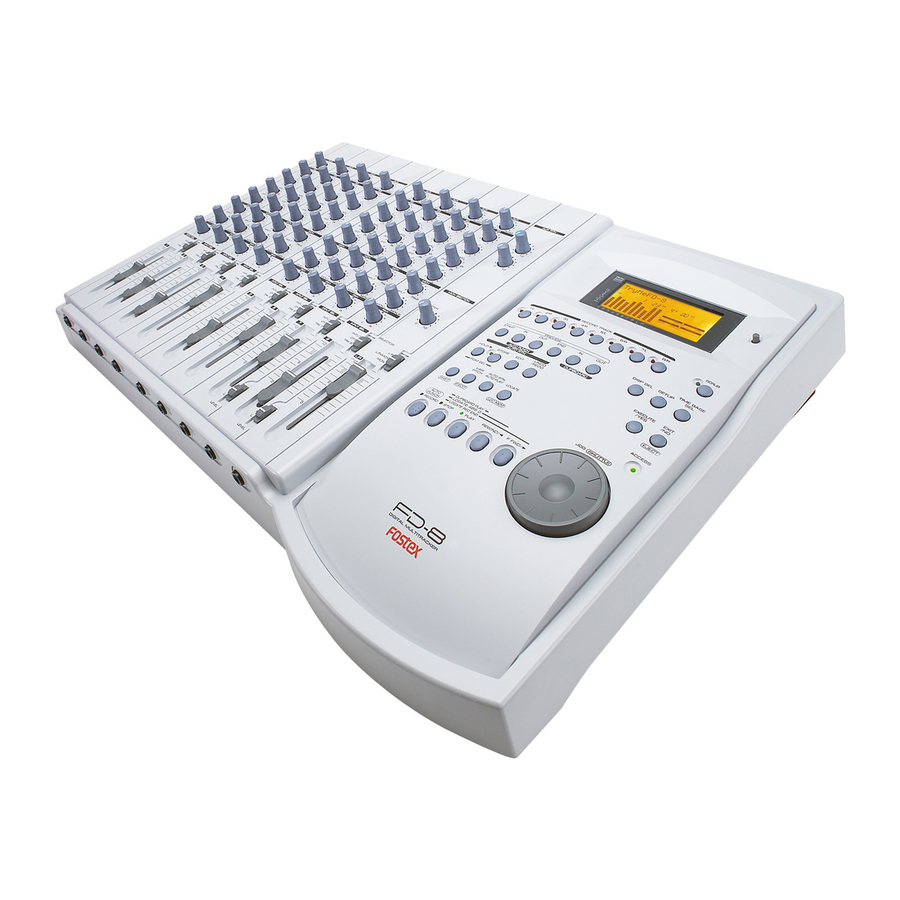
Page 7: Controls, Indicators And Connectors
FD-8 2. CONTROLS, INDICATORS & CONNECTORS Rear Panel Control Panel Front Panel... - Page 8 FD-8 Control Panel (Mixer Section) 1. Input faders [ 1-8 ] 2. Input select switches [ INPUT SEL (INPUT/OFF/TRK) ] 3. Panpot knobs [ PAN (L/R) ] 4. Monitor panpot knobs [ PAN (MON L/MON R) ] 5. Monitor level control knob [ MON (INPUT/TRK) ] 6.
- Page 9 38. Auto Punch In key [ AUTO PUNCH IN/ 39. Auto Punch Out key [ AUTO PUNCH OUT/ 40. Clipboard In key [ CLIPBOARD IN/ 41. Clipboard Out key [ CLIPBOARD OUT/ 42. Scrub key [ SCRUB ] FD-8 PREVIEW PREVIEW PREVIEW PREVIEW...
-
Page 10: Front Panel
FD-8 Front Panel 1. Input jacks [ 1, 2, 3, 4, 5, 6, 7, 8 ] ( Phone ) 2. Headphone jack [ PHONES ] ( TRS Phone ) Rear Panel 1. Monitor Out jacks [ MON OUT L, R ] ( RCA pin ) 2. -
Page 11: Software Update
“4-8. Flash ROM” (page 17). The SCSI ID to be connected to the FD-8 must be selected to 0 ~ 5. The SCSI ID “6” is used for backing up purpose exclusively. The SCSI ID “7” cannot be used by technical reasons. -
Page 12: Service Mode
Connect a SCSI device, insert the diskette formatted by the FD-8 and turn the power of SCSI device on. After confirming that the access LED on the SCSI device is lit and then goes out, turn on the power of FD-8. - Page 13 (2, 4, 6, 8 and R) channels indicate the left and right input level of S/P DIF digital signal fed to the DATA INPUT jack respectively. If the FD-8 is not in a normal condition, “DIGITAL” will blink and the bargraph meter will not indicate any level. FD-8...
- Page 14 To execute this test, press the EXECUTE/YES key while “?” is blinking. If the FD-8 is in a normal condition, all the segments on the LCD display will be lit solid and all the LEDs on the top panel will start blinking.
- Page 15 8 LCD display in order. If a 2.5" internal E-IDE hard disk drive is not installed in the FD-8, the Self Check mode comes to a standstill at “ATA Bus C (check)” test. In order to continue the Self Check mode, press the EXECUTE/YES key again.
- Page 16 FD-8 From previous page The followings are examples of error message when the FD-8 is not working properly. • SCSI function • Digital Signal in/out (Fs: 44.1kHz) 4-6. Offset Display If the FD-8 is in a good condition, “Check OK!” will be...
- Page 17 Plug the EPROMs into the sockets. Turn on the power of FD-8. In this condition, the FD-8 is booted up using the system software inside the EPROMs. The next procedures to take are as follows. Put the FD-8 into the Service Mode, select “FlashROM” and press EXECUTE/YES key. (“SURE?” is blinking.) Press the EXECUTE/YES key one more time to copy the system software from EPROMs to Flash ROM.
- Page 18 This mode is used to check the condition of the diskette : blinking inserted into an external SCSI drive connected to the FD-8 or the internal E-IDE hard disk drive. (As mentioned before, the SCSI drive has a priority unless the SCSI ID is set to “6”.)
-
Page 19: Error Code List
The chart below indicates the error code number and corresponding description. Since the error code list is basically designed for our engineers to improve the software, the description is quite technical. If you find the FD-8 with one of the error codes displayed, we encourage you to update the software first. -
Page 20: Installing 2.5" Internal Hard Disk Drive
• 8 x screws (P 3 x 5 CZn) Installing Procedures Loosen 17 x screws (BBT 3 x 8 BZn) fixing the FD-8 Top Panel section to the Bottom Panel section. Remove the following cables from the connectors on the MAIN PCB assy. - Page 21 Not like the FD-4 MAIN PCB assy, the E-IDE 50-pin connector J12 and 2-pin cable between W1 and W5 have already been mounted and soldered. So, it is not necessary to remove the FD-8 MAIN PCB assy when installing a 2.5” E-IDE hard disk drive.
- Page 22 • 9-pin cable to the J3 (from MIXER B PCB assy) • 9-pin cable to the J7 (from DISPLAY PCB assy) Tighten 17 x screws (BBT 3 x 8 BZn) fixing the FD-8 Top Panel section to the Bottom Panel section.
-
Page 23: Exploded View, Pcb Assembly And Parts List
PCB assy, XLR, FD-4/8 8216 6841 00 Shield, mixer, FD-8 8226 2370 00 Button assy, control, FD-4/8 8274 1260 00 PCB assy, Mixer B, FD-8 8226 2230 01 Knob, volume, C 8274 1560 00 PCB assy, Display, FD-8 8274 1570 00... - Page 24 FD-8 PCB PATTERN DRAWING • Parts Side of MAIN PCB assy J101 J201 TO MIXER LCH IN RCH IN TO MIXER 1-4CH C113 C213 C313 C103 C203 C102 C202 C114 C214 C314 C906 C154 C164 C264 C162 C262 C262 C152 1...
- Page 25 • Foil Side of MAIN PCB assy HCU04 D4 D3 U903 21035 HC14 HC32 J201 HC157 J101...
- Page 26 • MIXER A, JACK and XLR PCB assys INSERT3/7 INSERT4/8 L/MONO AUX RTN 1 C501 C503 R502 R501 R504 C603 C601 R601 R602 R604 C702 R702 R614 R802 C802 R803 R801 C801 R167 R163 R168 R164 R253 R153 R260 C264 R160 C165 R166...
- Page 27 • MIXER B PCB assy R102 R104 C101 R101 R202 C201 R201 R302 C301 R301 R402 C401 R401 C120 R112 U110 C118 R119 C113 C220 S102 R212 U210 C218 R219 C213 C320 S202 R312 U310 R319 C318 C413 C420 S302 R412 U410 S402...
- Page 28 • DISPLAY PCB assy GREEN MAIN GREEN GREEN GREEN...
- Page 29 • POWER PCB assy COUT2 COUT1 DGND DGND A+12 AGND AGND A–12 8251523 000 PCB POWER FD-8 CAUTION RISK OF ELECTRIC SHOCK ZONE T800mA 250V...
- Page 30 U013 8236 5025 00 ST, analog, reset, NJM2103M U014 8236 5701 01 ST, digital, driver, DTC114EK U015 8236 0838 02 QFP, digital, CPU, main, FD-8, mask, SH7042, F28 U016~019 U020~023 8236 5704 01 ST, digital, driver, DTA114EK U024 8236 5600 32 ST, digital, 74HC32...
- Page 31 C111~811 8232 1431 06 VT, ALU, 16V, 10µF, 20%, SME-VB C112~812 8233 5006 81 ST, CER, 50V, 680pF, 5%, CC20SL C113~413 8233 5041 03 ST, CER, 25V, 0.01µF, 10%, CC20R C114~414 8233 5041 03 ST, CER, 25V, 0.01µF, 10%, CC20R C115~815 FD-8...
- Page 32 FD-8 Ref. No. Part No. C116~816 8232 1434 76 VT, ALU, 16V, 47µF, 20%, SME-VB C151 C152 8233 5041 03 ST, CER, 25V, 0.01µF, 10%, CC20R C153 8232 1431 06 VT, ALU, 16V, 10µF, 20%, SME-VB C154 8233 5041 03 ST, CER, 25V, 0.01µF, 10%, CC20R C155 8233 5021 04 ST, CER, 50V, 0.1µF, +80-20%, CC20F...
- Page 33 C153, 253 8232 8011 01 VT, CER, 50V, 100pF, 5%, SL C154, 254 8232 8011 01 VT, CER, 50V, 100pF, 5%, SL C155, 255 8232 1431 06 VT, ALU, 16V, 10µF, 20%, SME-VB C160, 260 8232 1424 76 VT, ALU, 10V, 47µF, 20%, SME-VB FD-8...
- Page 34 8276 7790 20 Cable assy, 9P, WHT MT/F-MT/BS, L200 8277 4530 40 Cable assy, shield 2C, 6P, WHT8283-9073, L400 Part No. Description 8274 1260 00 PCB Assy, Mixer B, FD-8 8251 5160 00 Plain PCB, Mixer B, FD-8 Part No. Description RESISTORs Part No.
- Page 35 8274 1240 00 PCB Assy, XLR, FD-4/8 B001 8251 9672 03 Plain PCB, XLR, FD-4/8 Ref. No. Part No. Description J001, 002 8245 2680 03 Connector, PL, XLR 31, 3P, NC3FAH20 J003 8245 1721 06 Connector, PL, jack, 8283, 6P, WHT FD-8...
- Page 36 FD-8 • DISPLAY PCB assy Ref. No. Part No. 8274 1560 00 PCB Assy, Display, FD-8 B001 8251 5181 00 Plain PCB, Display, FD-8 Ref. No. Part No. U001 8236 0835 01 QFP, digital, CPU, FD4/8-display U002 U003 8236 0836 00 QFP, digital, LCD driver,...
- Page 37 • POWER PCB assy Ref. No. Part No. Description 8274 1580 00 PCB Assy, Power Supply, FD-8 B101 8251 5230 00 Plain PCB, Power Supply, FD-8 Ref. No. Part No. Description U001 8236 5410 03 V, analog, power, MIP163 U002 8234 1081 00 Opt., H, photo coupler, ON3171...
-
Page 38: Circuit Diagrams
8. CIRCUIT DIAGRAMS BLOCK DIAGRAM INPUT SEL INPUT INPUT1 INPUT -10dBV TRK1 FADER INPUT TRK1 INPUT1 INPUT2 INPUT6 INSERT7 INPUT7 INPUT SEL -50~-10dBV INPUT INPUT UNBAL TRK7 FADER TRIM INPUT TRK7 INPUT7 INPUT8 L/MONO -20dBV AUX RTN AUX RTN1 AUX RTN2 MASTER AUX1 GAIN... - Page 39 MIXER A, INPUT 5 ~ 8 CONNECTION (1/6) REPRO INPUT5 /REC MUTE5-8 REPRO5 REPRO5 REPRO5 REPRO6 REPRO7 REC MUTE5 REC MUTE5 REPRO8 R.MUTE5 R.MUTE6 R.MUTE7 +12V +12V R.MUTE8 AGND AGND AGND -12V -12V INPUT6 REPRO6 REPRO6 REC MUTE6 REC MUTE6 +12V +12V AGND...
- Page 40 MIXER A, MASTER (2/6) C152 R155 120K +12V C150 47/10 R156 AUX1 C151 4558 C153 100P -12V C252 R255 120K +12V C250 47/10 R256 AUX2 C251 C253 4558 100P -12V STEREO L STEREO R C170 R170 47/10 AUX RTN 1L R172 C172 470P...
- Page 41 MIXER A, INPUT 5 (3/6) +12V C530 C503 100P C504 R504 C502 R502 47/10 10/16 U501A 4558 R503 100k J501 C531 -12V INPUT5 R501 U510 C501 100k DTC143 100P REC MUTE5 REPRO5 R536 +12V +12V AGND -12V AGND R537 -12V C512 R517 R520...
- Page 42 MIXER A, INPUT 6 (4/6) +12V C630 C603 100P C604 R604 C602 R602 47/10 10/16 U601A R603 4558 100k J601 C631 -12V INPUT6 R601 U610 C601 100k DTC143 100P REC MUTE6 REPRO6 R636 +12V +12V AGND -12V AGND R637 -12V C612 R616 R617...
- Page 43 MIXER A, INPUT 7 (5/6) GAIN *40dB *20dB *0dB R708 S701B C704 R706 100/10 R710 200K J701 R704 +12V 200K C702 INPUT7 UNBAL R702 100P 100k C707 C701 R701 100k 100P U401A 2068 S701A C703 INPUT7H R707 100/10 -12V INPUT7C R705 R703 R709...
- Page 44 MIXER A, INPUT 8 (6/6) GAIN *40dB *20dB *0dB R808 S801B C804 R806 100/10 R810 200K J801 R804 200K INPUT8 UNBAL C802 R802 100P 100k C807 C801 R801 100k 100P U401B 2068 S801A C803 INPUT8H R807 100/10 INPUT8C R805 R803 R809 200K 200K...
- Page 45 MIXER B, INPUT 1 ~ 4 CONNECTION (1/5) RE PRO 1 RE PRO 2 RE PRO 3 RE PRO 4 RE C M U T E 1 RE C M U T E 2 RE C M U T E 3 RE C M U T E 4 A G N D RE PRO /RE C M U T E...
- Page 46 MIXER B, INPUT 1 (2/5) +12V C130 C103 100P C104 R104 C102 R102 47/10 10/16 U101A 4558 R103 100k J101 C131 -12V INPUT1 R101 U110 C101 100k DTC143 100P REC MUTE1 REPRO1 +12V R136 +12V AGND -12V AGND R137 -12V C112 R116 R117...
- Page 47 MIXER B, INPUT 2 (3/5) +12V C230 C203 100P C204 R204 C202 R202 47/10 10/16 U201A R203 4558 100k J201 C231 -12V INPUT1 R201 U210 C201 100k DTC143 100P REC MUTE1 REPRO1 +12V R236 +12V AGND -12V AGND R237 -12V C212 R216 R220...
- Page 48 MIXER B, INPUT 3 (4/5) +12V C330 C303 100P C304 R304 C302 R302 47/10 10/16 U301A R303 4558 100k J301 C331 -12V INPUT 1 R301 U310 C301 100k 100P DTC143 REC MUTE1 REPRO1 R336 +12V +12V AGND -12V AGND R337 -12V C312 R316...
- Page 49 MIXER B, INPUT 4 (5/5) +12V C430 C403 100P C404 R404 C402 R402 47/10 10/16 U401A 4558 R403 100k J401 C431 -12V INPUT1 R401 U410 C401 100k DTC143 100P REC MUTE1 REPRO1 +12V R436 +12V AGND -12V AGND R437 -12V C412 R416 R417...
- Page 50 ANALOG I/O & XLR AUX RTN 1 L/MONO AUX RTN 2 L/MONO INSERT7 INSERT8 AUX RTN 1 L STEREO L AUX RTN 1 R STEREO R AUX RTN 2 L MONITOR L AUX RTN 2 R MONITOR R INSERT7 SEND AUX1 AUX2 INSERT8 SEND...
- Page 51 DISPLAY, ROOT (1/3) 10/16 Non_79L05A 0.1A 10/35 (F10 JUMPER) /ATN1 > RxD1 < TxD1 > SCK1 > To MAIN /ATN2 < /RST_DISP > DGND A-12 BOADIN 9P DGND DGND DGND Non_10/16 Non_0.1 E101 Non_TP DGND (-12V) Vlcd /ATN1 /ATN2 470p JOG1 JOG0 DGND...
- Page 52 DISPLAY, LCD (2/3) SEG22 SEG21 SEG20 SEG19 SEG18 SEG17 SEG16 SEG15 SEG14 SEG13 SEG12 SEG11 SEG10 SEG9 SEG8 SEG7 SEG6 SEG5 SEG4 SEG3 DGND SEG2 SEG1 DGND Vlcd Vlcd DGND Non_1/50 (F5 Jumper) R11 1k R12 1k No n_LA5640N R14 1k R43 10k Lo<...
- Page 53 DISPLAY, KEY & LED (3/3) R17 1 00k JO G0 JO G1 R20 1 00k SCA N[0..4 ] SCA N[0..4 ] SCA N0 S/R 8 SCA N1 S CRUB SCA N2 UNDO/RE DO SCA N3 SCA N4 Non _TA CT R30 22k DGND KEY[0..7 ]...
- Page 54 POWER SW1-2 BL 250VAC/0.8A 6HOLE AC IN 0.0022/250VAC 0.1/250VAC AC IN 0.0022/250VAC LINE FILTER 1mH/2.2A 6HOLE DB-S 33/0.5W 100/400V MA649 LINE FILTER 19mH/0.5A 0.01/630V 100k/2W DIN60 EK13 330/25V EK13 IPD MIP TRANSE 3 47/25V MA171 ON3171 0.0022/250VAC 0.0022/250VAC 390P/500V 10uH/2A 470/25V 470/25V DGND...
- Page 55 MAIN, ROOT (1/10) AD-DA A+12 AGND HP AD-DA A+12 AGND A-12 MUTE REC_L REC_R A-12 AGND MUTE MUTE 8283M7P REC_L REC_L REC_L REC_R REC_R REC_R TO MIXER W101 A+12 RCA-JACK-SW A+12 A+12 J101 A-12 A-12 A-12 L101 W201 REC IN AGND AGND J201...
- Page 56 MAIN, CPU (2/10) R_MUTE1 R_MUTE2 R_MUTE3 R_MUTE4 ADDA R_MUTE[1..8] R_MUTE[1..8] R_MUTE5 R_MUTE6 A-12 A-12 R_MUTE7 R_MUTE8 DGND DGND A-12 MEMORY DGND /EPROM /EPROM FM_RDY FM_RDY ADDA D[0..15] D[0..15] D[0..15] A[0..18] A[0..18] A[0..18] MEMORY DGND DGND DGND RDWR RDWR RDWR /CS0 /CS0 /CS0 /CS2...
- Page 57 MAIN, MEMORY (3/10) EPROM1 EPROM2 DGND 0.01 HN27C4001G-SOCKET DGND Under 2M 2M of 4M DGND FM_RDY /CS0 /CS_EPROM /CS0 /CS2 /CS2 /CS_FLMEM /CS2 /CS0 /EPROM 74HC157 0.01 DGND DGND DGND DGND FLASH MEMORY DQ10 DGND DQ11 DQ12 DQ13 DQ14 DQ15 0.01 HN27C4001G-SOCKET C100...
- Page 58 MAIN, GATE ARRAY (4/10) VCO+5 VCO+5 POWER VCOGND VCOGND 0.01 0.01 10/16 POWER 0.01 0.01 DGND DGND DGND SCSI /ATA_RST /ATA_RST /ATA_RST DD10 DD[0..17] DD11 DD[0..17] DD[0..17] DD12 DD13 DD14 DD15 DMARQ DMARQ DMARQ /DIOW /DIOW /DIOW /DIOR /DIOR /DIOR IORDY_I IORDY_I IORDY_I...
- Page 59 MAIN, SCSI I/F (5/10) /ATA_RST DMARQ IORDY_I INTRQ /ATA_RST DGND DD10 DD11 DD12 DD13 DD14 DD15 /DIOW DGND /DIOR KEYPIN /DMACK DMARQ DGND TO IDE HD /DIOW DGND /DIOR DGND IORDY DMACK DGND INTRQ /IOCS16 ATA1 /PDIAG ATA0 ATA2 /CS1FX /CS3FX /DASP DGND...
- Page 60 MAIN, ADAC (6/10) NANDB0 NCO3 NANDB1 NCO2 NANDBO NCO1 NANDC0 NCO0 NANDC1 NANDCO NORA0 NORA1 NMLRCK NORAO C256FS NORB0 C512FS ADAC NORB1 N16BIT NORBO NRESET NORC0 NCS0 NORC1 NORCO MINTEST TEST0 TEST1 ADAC 0.01 0.01 0.01 0.01 DGND VARI/EXT_LRCK NANDB0 NCO3 NANDB1 NCO2...
- Page 61 MAIN, ROOT, ADDA (7/10) G=-4.5dB C101 R101 10/16 REC_L MIXER R109 100K C107 C104 0.01 C201 R201 10/16 REC_R MIXER R209 100K C207 MUTE C204 0.01 R908 VBIAS R909 C903 C904 0.01 10/16 MUTE AGND A+12 /MUTE RB400D R912 C913 R906 U901 100/25...
- Page 62 MAIN, AD-DA (8/10) AIN2+ AIN2- AIN1+ AIN1- C155 U151 AGND C153 C154 AINR+ 10/16 0.01 AINR- SMODE VREF CMODE SDATA AGND FSYNC AINL+ LRCK AIN- SCLK C151 TST1 MCLK C152 HPFE AGND 0.01 TST2 SMODE2 TST3 TST4 D+5_1 DGND AK5351 R151 C156 C157...
- Page 63 MAIN, ANALOG OUT (9/10) A+12 C113 0.01 U153A C111 10/16 NJM4565M AGND AOUT1+ R111 R113 2.7K C115 C112 R112 680P A-12 C114 0.01 C211 U153B 10/16 NJM4565M AOUT2+ R211 R213 2.7K C215 C212 R212 680P A+12 C213 0.01 U253A C311 NJM4565M 10/16 AGND...
- Page 64 MAIN, VCO1 (10/10) PLL_SEL VCO+5 FCONT1 VCO+5 POWER VCOGND VCOGND VARI/EXT_LRCK VCO+5 22uH 0.01 0.01 R39 10K VCO+5 VCOGND LOCK 8.2K VDDA AMPI AMPO VSSA 0.47 TC9246F 0.01 0.01 VCOGND VCOGND VCOGND 0.01 VCO+5 22uH 0.01 0.01 VCOGND 1.5K LOCK VDDA AMPI AMPO...
- Page 65 FD-8 < NOTE >...
- Page 66 FOSTEX CORPORATION 3-2-35 Musashino, Akishima, Tokyo, Japan 196-0021 FOSTEX CORPORATION OF AMERICA 15431 Blackburn Ave., Norwalk, CA 90650, U.S.A. © PRINTED IN JAPAN SEP 1998 8288775000...