Review

Real Driving Emission Calibration—Review of Current Validation Methods against the Background of Future Emission Legislation

Institute for Combustion Engines, RWTH Aachen University, 52074 Aachen, Germany
*
Author to whom correspondence should be addressed.
Appl. Sci. 2021, 11(12), 5429; https://doi.org/10.3390/app11125429
Submission received: 30 April 2021 / Revised: 25 May 2021 / Accepted: 27 May 2021 / Published: 11 June 2021
(This article belongs to the Section Robotics and Automation)

Abstract

:
Reducing air pollution caused by emissions from road traffic, especially in urban areas, is an important goal of legislators and the automotive industry. The introduction of so-called “Real Driving Emission” (RDE) tests for the homologation of vehicles with internal combustion engines according to the EU6d legislation was a fundamental milestone for vehicle and powertrain development. Due to the introduction of non-reproducible on-road emission tests with “Portable Emission Measurement Systems” (PEMS) in addition to the standardized emission tests on chassis dynamometers, emission aftertreatment development and validation has become significantly more complex. For explicit proof of compliance with the emission and fuel consumption regulations, the legislators continue to require the “Worldwide Harmonized Light Duty Vehicle Test Cycle” (WLTC) on a chassis dynamometer. For calibration purposes, also various RDE profiles are conducted on the chassis dynamometer. However, the combination of precisely defined driving profiles on the chassis dynamometer and the dynamics-limiting boundary conditions in PEMS tests on the road still lead to discrepancies between the certified test results and the real vehicle behavior. The expected future emissions standards to replace EU6d will therefore force even more realistic RDE tests. This is to be achieved by significantly extending the permissible RDE test boundary conditions, such as giving more weight to the urban section of an RDE test. In addition, the introduction of limit values for previously unregulated pollutants such as nitrogen dioxide (NO2), nitrous oxide (N2O), ammonia (NH3) and formaldehyde (CH2O) is being considered. Furthermore, the particle number (for diameters of solid particles > 10 nm: PN10), the methane (CH4) emissions and emissions of non-methane organic gases (NMOG) shall be limited and must be tested. To simplify the test procedure in the long term, the abandonment of predefined chassis dyno emission tests to determine the pollutant emission behavior is under discussion. Against this background, current testing, validation, and development methods are reviewed in this paper. New challenges and necessary adaptations of current approaches are discussed and presented to illustrate the need to consider future regulatory requirements in today’s approaches. Conclusions are drawn and suggestions for a robust RDE validation procedure are formulated.

1. Introduction

Reduction of emissions is one of the most important goals in shaping future mobility without negative effects on human health and the environment. This is counteracted by the permanent growth of the world’s population and the concomitant increase in motorized individual mobility [1,2,3]. The constant evolution of the pollutant and CO2 emission standards is a technology driver that is forcing the automotive industry to continuously develop ever more robust powertrains and emission control as well as exhaust gas aftertreatment systems.
In contrast to the comparatively moderate adjustments of the emission standards in recent decades, the introduction of the current EU6d legislation was a milestone for the requirements on the development of emission reduction technologies as shown in Figure 1. Since the introduction of Real Driving Emissions (RDE) tests, pollutant emissions must be validated and reported under real road and traffic conditions and not only in the driving cycles on a chassis dynamometer that were exclusively relevant to legislation so far [4]. Many Original Equipment Manufacturers (OEM) implemented task forces to avoid having to discard the planned Starts of Production (SOP) for their products, some were even forced to reduce their product portfolio [5]. This is due to the wide range of possible testing conditions already required by the current legislation to cover all possible test scenarios for RDE [6].
Current proposals and discussions in the context of an upcoming EU7 legislation indicate that a further milestone for powertrain development must be reached [7]. This will pose new challenges for the automotive industry, but also for the manufacturers of Portable Emission Measurement Systems (PEMS).
In this paper, these challenges are discussed with focus on the field of emission calibration. Therefore, current publications are reviewed for proposals and prognoses concerning the next steps of the emission legislation. The findings are summarized in the chapter “Challenges posed by the upcoming emission legislation”. Subsequently, the problems are transferred to the subject area of emission calibration. For this purpose, the entirety of the changes is condensed into four core elements, which require a review or action in regard to established development methods.
For these core elements, a problem analysis is performed in “Problem analysis and consequences of potential legislative amendments for calibration”. Accordingly, all four issue blocks are addressed separately and challenges for vehicle development and especially for emission calibration are identified.
Current RDE development and testing methods are examined for their future practicability in “Review of current methodologies against the background of calibration challenges”. The extent to which existing development methods can meet the future requirements is analyzed. Necessary changes are examined and discussed, provided they can be implemented in the respective approaches.
Once specific tasks have been identified, the chapter “Implementation of solutions and presentation of a suitable RDE development and validation methodology” will provide concrete solutions. In this context, a methodology is presented that is already able to meet many of the challenges of the upcoming legislative changes previously discussed.
The section entitled “Conclusions and Outlook” provides a compact summary of technical achievements with particular added value for automotive development and provides an outlook on further research activities in the area of RDE calibration methods.

2. Challenges Posed by the Upcoming Emission Legislation

Figure 2 shows an overview of the development of emissions legislation in Europe since 2015. The standards take into account technical trends and further developments that enable more non-critical emissions behavior while at the same time allowing for justifiable additional effort on the part of manufacturers and consumers. Forecasts and future scenarios are particularly important for OEM, as the development cycles of new hardware are in some cases longer than the current revision intervals of emissions legislation in Europe [8].
The overall objective of the regular revision of emission legislation is an improvement in air quality. In particular, zero-emission mobility in urban environments is focused since many years. The sometimes considerable discrepancies between emission results determined in the laboratory and PEMS measurement results on the road [9,10,11,12] have led to public discussions, juristic conflicts and consequently to local bans on vehicles of older construction years [7,13]. With the introduction of the “Worldwide harmonized Light duty vehicle Test Procedure” (WLTP), RDE tests were integrated into the vehicle homologation procedure in addition to chassis dyno tests in the laboratory environment.
Currently, a debate is taking place about the elimination of laboratory tests as main criterion for the evaluation of pollutant emissions for the period after EU6 [14]. The Clove Consortium states that so far “non-regulated pollutants (gaseous and particles) [shall] be included in the regulations and measured on board the vehicle with PEMS” [14].
Laboratory tests should then only be necessary, for example, to evaluate new pollutants for which an appropriate mobile measuring technology is not yet available. Additionally “for CO2 emission measurement and check of compliance with the fleet-based CO2 emission targets” [15], the WLTP chassis dynamometer tests could still be applied according to this reference. However, the actual “[pollutant] emission certification [will probably be]-based (solely) on RDE and PEMS testing” [15].
A further adjustment of the specifications is planned in the form of fuel and technology neutrality of emission standards [15,16]. Thus, there will probably be uniform limit values for petrol, diesel, and any hybrid applications. At the same time, it is likely that all fuels available on the market can be used for test purposes. Examples for the influence of the fuel on the particulate number (PN) emission result are given in [17,18,19,20,21,22,23]. The oxygen content in the fuel has a strong influence; increasing oxygen content in the fuel (e.g., in ethanol or methanol) causes a decrease in the total PN concentration and in the concentration of nucleation mode PN [24,25,26].
The importance of RDE will increase significantly as a result of these changes. Especially as the acceptance in society for emission results from measurements in real road traffic is higher than for the testing approach on chassis dynos used so far. However, the current legally defined boundary conditions for e.g., longitudinal vehicle dynamics or road topography still lead to discrepancies between compliant RDE test results and reality. The current conditions and limitations are highlighted in Figure 3.
With a clear differentiation of the drive profile into the urban, rural and motorway phases, the possible shares of speed ranges are clearly defined. On top of the speed itself, restrictions for allowed driving dynamics ranges are given by providing a maximum limitation for v·apos95 (95th percentile of the products of velocity and positive acceleration for each phase) and a minimum limitation for RPA (relative positive acceleration). Furthermore, the limitation of boundary conditions for temperature and altitude with the separation into moderate and extended conditions restrict the potential test scenarios compared to a possible real-world usage behavior.
To close this gap, the Clove consortium [14,15,27] recommends that RDE tests in the future should take into account all parameters mentioned below:
  • Driving dynamics
  • Ambient temperatures
  • Altitudes
  • Payloads
  • Types of driving distances with emphasis on short trips, cold starts, and warm starts
The last point is a particular challenge for emission measurement devices, because depending on the measurement principle (dry/wet), only a delayed recording of emissions is possible due to condensation effects at temperatures of exhaust gas components below the dew point [28].
Consideration of the approaches presented against the background of the available sensor and measurement technologies partially rules out some measures for the near future. However, a scenario for a gradual implementation in two stages is conceivable.
According to Clove, the following points must be realistically assigned to the long-term goals:
  • The test procedure must be able to monitor the vehicles’ cleanliness under (almost) all circumstances and boundary conditions and during its entire realistic lifetime [27].
  • Urban mobility must be (almost) emission-free. This should be “guaranteed via a combination of RDE and On Board Monitoring (OBM) systems“ [27,29]
  • Replacement of all chassis dynamometer type approval tests by RDE procedures [27].
These long-term goals must be noted and considered where possible for new developments. However, from the current perspective, the “short term scenario” is more important. It consists of the following proposals, which can technically be realized within a time horizon of a few years in advance:
  • OEM must ensure that emissions are low across the entire engine operation map by means of appropriate control mechanisms [27,30]. In recent years, feasibility of this topic has already been demonstrated by various studies, particularly in the context of CO emissions from gasoline engines [30,31,32].
  • In Service Conformity (ISC) will be checked by RDE tests until suitable OBM systems are available [27]. However, OBM will be introduced successively. A first sign has already been set by the introduction of the Fuel Consumption Monitoring (FCM) system within EU6d [33,34].
  • On Board Diagnostics (OBD) functionality is to be demonstrated under RDE conditions.
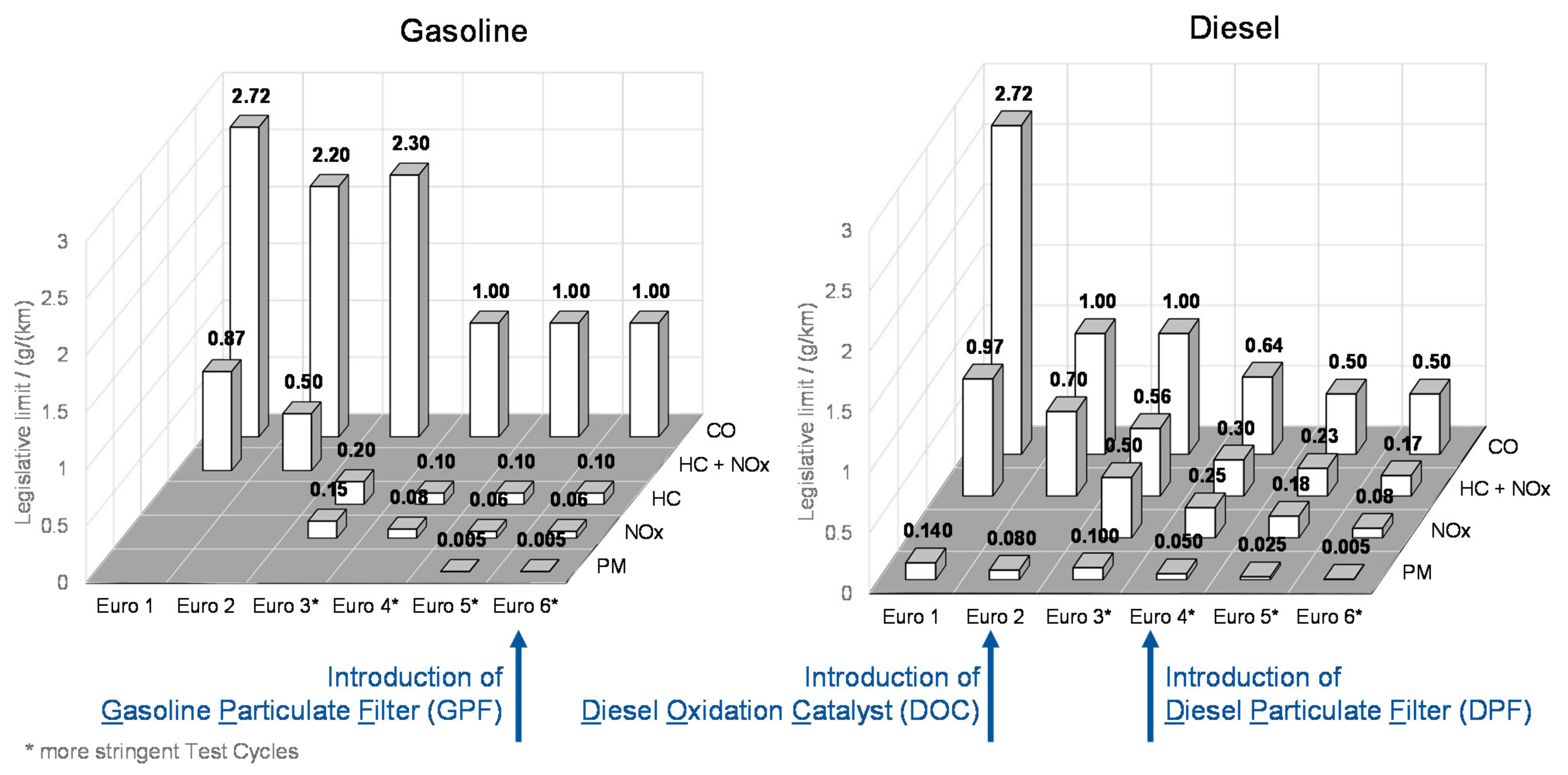
  • Implementation of stricter and uniform limit values for pollutant emissions of the various propulsion technologies [35].
  • Introduction of limits for additional pollutants [2,7,35]—new emissions species considered relevant are: nitrogen dioxide (NO2), nitrous oxide (N2O), ammonia (NH3), formaldehyde (CH2O), particle number (for diameters of solid particles > 10   nm : PN10), methane (CH4) and non-methane organic gases (NMOG) [15,36].
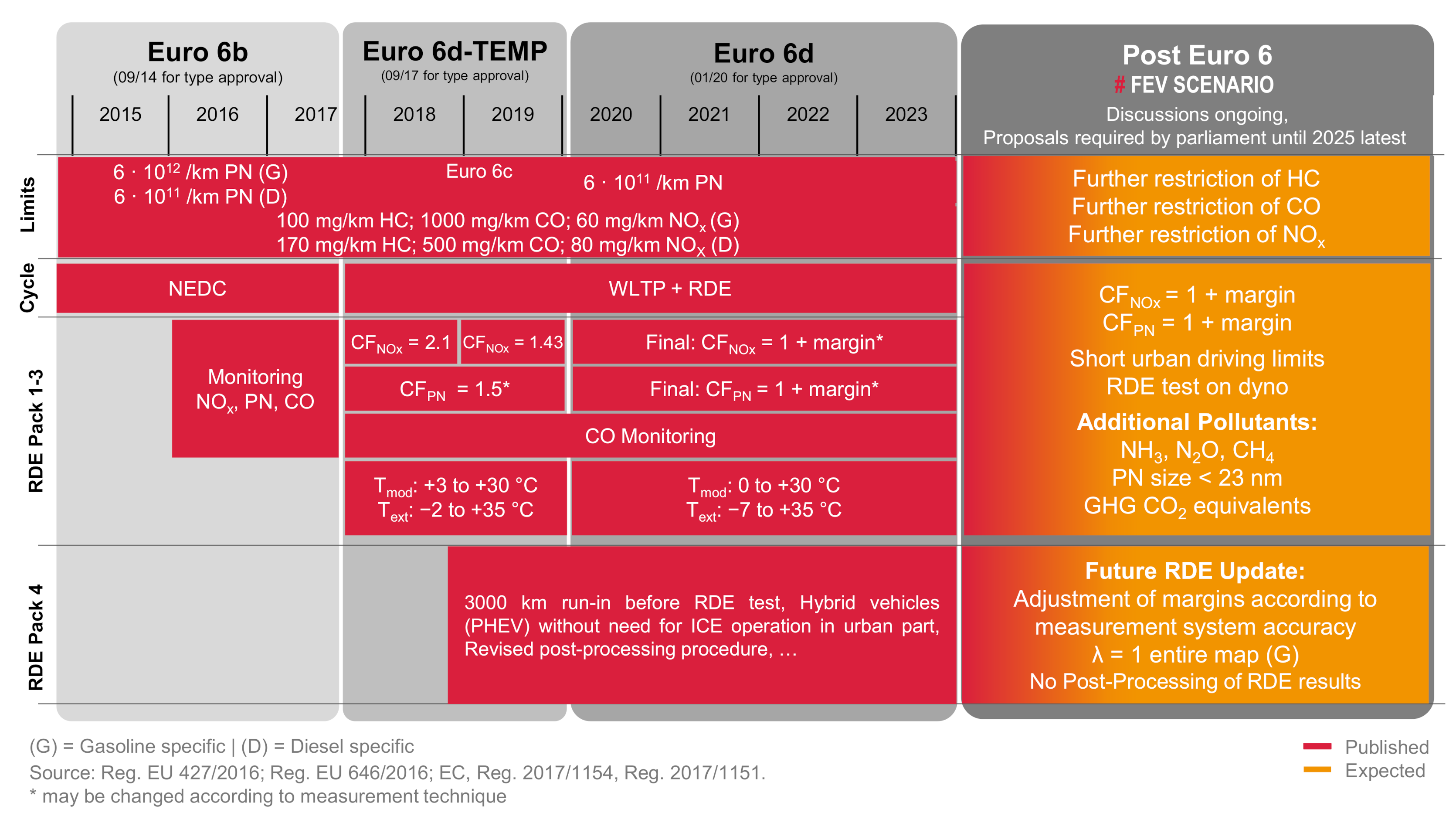
  • Type approval as such will continue to take place on the chassis dynamometer for an indefinite period of time and will be supplemented by RDE tests on the road. However, the focus could gradually (comparable to the stages between EU6b and EU6d (final)) be shifted more and more toward “certification of Air Pollutants and verification of [Green House Gases (GHG)]” [27] by RDE tests with PEMS. For many of the non-regulated pollutants, there are already promising approaches for on-road measurements. Examples are the measurement of N2O, NH3, CH4 and CH2O during on-road operation in [37], which shows good results in correlation with laboratory measurement technology. However, further testing is necessary [27].
  • The RDE test procedure will be significantly modified:
    Adaptation of the RDE boundary conditions with regard to the question “how are the cars in fact driven/used in practice?”—“Normal use and normal conditions across Europe will be reassessed to consider a more encompassing RDE” [27].
    Definition of a significantly “wider RDE testing range” [15].
Future ISC tests with PEMS will require additional testing effort. Additionally, the shift of OBD demonstrations from the chassis dynamometer to the road means a change in processes and an increased demand for mobile emission measurement technology. Considering the results of the comprehensive market analysis on emission measurement technology, shown in Figure 4, an increase of 67% can be expected between the date of introduction of EU6d (2019) and the earliest possible introduction of EU7 (~2025).
Between the introduction of EU6b and EU6d, the Grand View Research Inc. study “Vehicle Emissions Test System Market: ANALYSIS AND FORECASTS FROM 2016 TO 2027” shows a market growth of about 90%. This relative increase also correlates with the increase in the number of emission tests carried out during this period, due to the increased need for validation per product resulting from the introduction of WLTP and RDE. Accordingly, an increase in the number of tests required for the next emissions legislation step can be anticipated.
In the future, the significant increase in need for testing will result in particular from RDE tests, which already represent a significant part of the validation process. An overview of the upcoming changes under discussion shows that the importance of RDE is growing rapidly in the context of future legislation and vehicle homologation. This paper therefore focuses on the question: “What do the upcoming changes in the legislation mean for the existing RDE test procedures and how can we ensure that newly developed vehicles will be clean within the wider RDE test range?
This is discussed in terms of the following key challenges to be considered:
  • “New pollutants”—Is measurement technology up to the task?
  • Progressive shift of test operations from the laboratory onto the road
  • Increase of possible test cases: “Wider RDE testing range” in “order to address all driving conditions” [14]
  • Vehicle testing according to actual use: “Normal use and normal conditions will be reassessed” [15]

3. Problem Analysis and Consequences of Potential Legislative Amendments for Calibration

The measurement of previously unregulated pollutants is a challenge for various reasons. Additional measurement technology is required and the necessity to measure pollutant emissions mainly in real road traffic in the future requires mobile measurement systems with sufficiently accurate sensor technology.

3.1. “New Pollutants”—Is Measurement Technology up to the Task?

State-of-the-art PEMS are equipped with sensors for concentration measurement of nitrogen oxides (NOX), carbon monoxide (CO) and carbon dioxide (CO2) as well as for counting PN (with diameters >23 nm: PN23). In addition, the PEMS setup includes an exhaust gas mass flow measurement (EFM) system, a Global Positioning System (GPS) and an energy source. Each additional analyzer requires further installation space in the already very compact PEMS design [39]. The compact design causes compromises in measurement accuracy (currently the law allows 50% deviation for PN and 43% for NOX) [4]. Since PEMS are operated under strongly varying environmental conditions (temperature, humidity) and are subject to strong accelerations and shaking, they are designed simpler than laboratory devices in order to increase robustness. This is another reason for the higher measurement uncertainty compared to the laboratory grade equipment [40,41].
Mobile measuring systems are already available on the market for some of the potentially future regulated gaseous pollutants. Some of those new pollutants can be measured quite satisfactorily with such systems [37].
In contrast to the gaseous emissions, the results for the measurement of ultrafine particles (PN10) are subject to high inaccuracies. Dorscheidt et al. show that PN10 can account for up to 50% of the total PN result when a vehicle is operated dynamically on a chassis dynamometer [42]. For these investigations, a selection of gasoline vehicles with state-of-the-art aftertreatment systems including a gasoline particulate filter (GPF) have been used. Figure 5 shows measurement results of PN10 and PN23 and their respective share of the total PN emission result. The investigation points out how critical a deviation of only 50% in PN10 can be for the overall result.
The diagram shows the PN results in a WLTC for a J-, S- and A-class vehicle, each equipped with a state-of-the-art emission aftertreatment system including a GPF. These were measured on the emission chassis dynamometer with a Cambustion DMS500 [43] and a condensation particle counter (CPC—[44,45,46]). On the other hand, measurement results of selected stationary operating points (measured upstream and downstream of the GPF) of the S-class vehicle are shown. For this purpose the DMS500 was set up on the engine test bench.
The significant share of PN10 on the total PN results is also confirmed by the results of another study on the “Laboratory and On-Road Evaluation of a GPF-Equipped Gasoline Vehicle”, which shows proportions between 20% and 50% [47].
PEMS for PN10 are part of different studies that show large scattering measurement results [48,49]. Particularly in direct comparison with laboratory equipment, clear deviations are detected. The “Assessment of 10 - nm Particle Number (PN) PEMS” [40] summarizes that the most accurate system shows ±25% deviations. However, depending on the measuring principle, deviations between 25% and 100% can be observed:
  • CPC systems had 25% to 50% differences compared to the reference systems
  • diffusion charger systems had 50% to 100% differences [40]
The use of the current PN10 mobile emission measurement technology would therefore in some cases falsely generate results that exceed the legal limit. If the legislator provides a sufficiently high Conformity Factor (CF), this is acceptable for individual homologation tests, but not for development purposes where high measurement accuracy is required for system optimization.
On top of challenges regarding the robustness and availability of measurement devices for the new pollutants, the impact of adjusted boundary conditions needs to be considered for PEMS devices. Yet difficult measurement procedures for e.g., HC and NH3 species as well as procedures for already PEMS relevant pollutants must work securely and reliably under all ambient conditions. This includes low temperatures (likely down to −10 °C) and high temperatures (likely up to 45 °C) at high altitudes of around 1600 m above sea level [50].
Furthermore, the extended range of operation as a consequence of potentially omitted boundary conditions for the dynamics of a test cycle may lead to a high variance of exhaust gas mass flows during a single test. The measurement device must then be able to capture low mass flows during low load urban operation as well as extremely high mass flows at high speed motorway driving with a sufficient accuracy [50].
Extending the on-road measurements from PEMS to in-vehicle OBM systems within a future legislation to track the fleet’s emission conformity in use during the vehicle’s lifetime rises the need for adequate measurement devices and technologies. Accordingly, sensors need to be implemented into the exhaust aftertreatment system that are capable of identifying all relevant pollutant components. Such sensors must be installed in a highly limited space—extreme reduction compared to PEMS—with a sufficient level of accuracy—comparable to PEMS—at the same time [51]. Within current EU6d, the legislator already allows a conformity factor of 1.43 to 1.5 to compensate the variance of PEMS test results due to the device’s tolerances [4]. Performing a PEMS test with a duration of roughly two hours necessitates a pre-calibration and post-check for each test. A reduction of calibration intervals for OBM hard- and software is required with adequate procedures to compensate or prohibit measurement drift to allow a normal operation of the vehicle in daily use. Considering high variances in boundary conditions with extreme levels of experienced limits (real vehicle use instead of legislative test conditions) further complicates the design of systems with a reasonable robustness. This includes the durability and the resistance against cross sensitivities.

3.2. Progressive Shift of Test Operations from the Laboratory onto the Road

For emission optimization and calibration in general, reproducibility of test results and test conditions is essential. For example, for calibration of catalyst purge strategies or the optimization of the lambda controller downstream catalyst, the effect of smallest calibration changes on the emission results must be assessed over several calibration loops. Disturbances in form of varying boundary conditions must be excluded. This is only possible in a laboratory environment. The required degree of reproducibility for the successful completion of development projects cannot be achieved during road tests [52].
The “non-exhaust emissions” behavior [15], which is also discussed and which is the result, for example, of abrasion of the tires and brakes while driving, is very strongly influenced by the driving style and driving behavior, as well as the used components. From the perspective of calibration, these emissions would then become an issue if a combined PN limit value would be implemented. Calibration would then have to reduce exhaust emissions to such an extent that the limits would be met with all conceivable combinations of particulate emissions from tires and brakes. Otherwise, all vehicle-specific consumable parts and their manufacturers would have to be defined prior to homologation.

3.3. Increase of Possible Test Cases: “Wider RDE Testing Range”

The extension of the defined boundary conditions in RDE testing is accompanied by an increase in the number of test cases required for calibration and validation. Adjusting or even eliminating the required minimum driving distances for a valid RDE test results is a significant challenge for calibration due to the high emission level during cold start and warm-up phase [53,54]. Shortening the required total driving distance results in only a reduced distance to “dilute” the start emissions by the range covered in warm condition. For demonstration, the distance specific and cumulated PN, NOX and CO emissions for a WLTC test on a chassis dyno with a 1.6 l 155 kW GDI 1783 kg D segment vehicle with a state-of-the-art exhaust aftertreatment system including a three-way catalytic converter and a GPF are shown in Figure 6. Due to the cold system conditions, the increased raw emissions, and the low conversion rate of the aftertreatment system lead to a high increase of cumulated emissions within the first 100 s. Once the catalytic converter has reached the light-off temperature, the conversion of the raw emissions reaches a suitable efficiency, leading to a clear reduction in tailpipe emissions. The distance specific intensity indicates the diluting effect of the following test distance on the overall result. Even a shorter distance after a cold-start with restricted driving dynamics [4] can significantly increase the emissions generated in this phase if higher loads and thus higher mass flows are provoked while the exhaust aftertreatment components have not yet reached the necessary operation and light-off temperatures. As a consequence, additional auxiliaries such as electrically or burner-heated exhaust aftertreatment systems must be applied to support the warm-up process [2,55,56,57,58]. Further measures such as the use of e-fuels for improved starting and emission behavior are conceivable to support an efficient calibration [59,60,61,62].
The removal of limitations for driving dynamics (RPA and v·apos95) as well as the topography of the route driven lead to a multitude of new engine operating conditions. In particular, the resulting dwell time in emission-critical engine operating points makes it difficult to robustly ensure emission compliance. Both the continuous operation in high load ranges and the operation at low load and low dynamics must be considered in the calibration [63]. Current concepts, which require enrichment for thermal component protection at high loads and exhaust gas temperatures, can no longer be used due to the expected combination of the elimination of driving dynamics limitations and additional emission restrictions (especially for CO). This will require a change to stoichiometric operation over the entire engine map [7,30,31]. Additionally, low loads in combination with changed driving route restrictions can lead to a slower warm-up of the components, especially during the urban phase as shown in [64].
Considering the increasing hybridization of current and future powertrains, the challenge of a wider range of potential operating points and operating point traces is further enhanced. This can result in hurdles and benefits at the same time. Being able to actively shift the operating point in load, speed and completely decouple it from the actual propulsion demand (based on the specific hybrid topology) allows optimizing the used operation area based on the emission behavior. At the same time, a compromise between emission optimization and reduction of fuel consumption needs to be addressed in the layout of the hybrid strategy calibration. This advantage of decoupling the engine may result with regard to temperature management of the engine and exhaust aftertreatment system. Repeated engine starts at temperatures with a low conversion efficiency may lead to an intensified emission behavior. Accordingly, the strategy calibration needs to consider the variable and unknown operation points. The engine may be restarted anytime with various speeds and loads if required; for example due to insufficient state of charge of the battery or a high propulsion power demand, exceeding the capacity of the electric machine.
Thus, profiles that were previously not permissible due to insufficient driving dynamics or an insufficient resulting urban share may lead to critical emission intensities in the future. As a consequence, the increasing number of applicable boundary conditions and the resulting challenges for emission control lead to an increase in the number of tests required for robust validation. However, the limited capacity of test facilities and test benches as well as measurement systems and vehicles, coupled with shorter available development times and limited program budgets restrict the expansion of test cases that can be investigated. To counteract this development and to further ensure both the time required and the statistical certainty for the development under all boundary conditions, a revision of the existing processes and tools for the calibration process is necessary.

3.4. Vehicle Testing according to Actual Use: “Normal Use and Normal Conditions Will Be Reassessed”

The question arises how normal operation can be defined. An important aspect is the evaluation and quantification of operational and driving behavior with the respective vehicle.
Within the RDE legislation, the key figures v·apos95 and RPA are implemented (Figure 3) [4]. However, these are not sufficient to clearly describe “normal use” [65]. The introduction of further indicators as described in [65,66] is an important next step. The goal of focusing test procedures and operating modes on typical usage affects the calibration itself, the design of tests, and the evaluation and interpretation of test data. The demand for more realistic operating modes in legal tests has already been pursued by the introduction of the WLTC. To design this test cycle, statistical data of typical driving behavior was collected and the speed profile was derived from this data [67,68]. More realistic tests cause more realistic emission results, e.g., compared to NEDC [69]. An equivalent approach was implemented in the Chinese emission legislation with the introduction of CATC [70]. With the goal of mapping geographically regional driving behavior in a more focused manner [71,72,73,74], local target group-specific data are also collected, evaluated and, for example, combined into a supplementary test cycle via Markov chains (further explained in [75,76,77,78]) as described in [79,80].
The shift away from predefined driving cycles to a focus on free RDE routes means however that the previously used approaches will also be revised in the future. Methods must be introduced that do not define statistically relevant driving profile sequences on the basis of databases, but rather determine statistical relevance by means of comparison algorithms. The EU6d standard does not specify any characteristic values that describe typical driving behavior. The driving dynamics-limiting parameters v·apos95 and RPA are only used to ensure comparable test requirements. The derivation of corresponding parameters and especially the determination of target values is highly relevant since the driving behavior influence the total emission results significantly [6,81], but remains open.
A definition of global statistical targets by the legislator remains difficult and impractical. Different vehicles and motorizations have correspondingly different statistically typical operating modes [82,83,84,85]. With the goal of individual relevance, a target-oriented concept must leave the verification of the statistical relevance of a test drive to the manufacturer. In addition to the additional implementation of methods with statistical relevance, an increased calibration effort is necessary. Already in the case of derivative changes, the following changed typical usage behavior can lead to a shift in the focus of the calibration. Even with the same test, the emissions of a uniform propulsion system can vary in different vehicles, as shown in [82]. With the introduction of typical driving behaviors in the future, not only the effects of the vehicle on the operating point, but also the shifting of the operating points due to changed driving behavior will require extended calibration scopes.

4. Review of Current Methodologies against the Background of Calibration Challenges

With the new challenges resulting from the expected changes by the introduction of a new EU7 standard, a review of the approaches used to support calibration and validation process becomes necessary. The methods currently in use have been implemented to address the changes brought about by the introduction of RDE in EU6d-temp. With the focus of ensuring emission compliance within all possible operation conditions during current RDE boundaries and reducing the required amount of prototype vehicles, several solutions have been introduced, as shown in Figure 7.
Specific requirements for an efficient EU7 validation methodology can be derived from the previous chapters:
  • Sufficient flexibility toward the measurement of additional pollutant emissions
  • Appropriate measurement accuracy in a suitable test environment
  • Ability to adapt new/modified RDE boundary conditions
  • Consideration of representative driver-vehicle-interaction (“normal use”)
  • Possibility to emulate all influencing ambient conditions
While not directly resulting from expected regulative changes, further demands for a successful and resource-saving calibration process are:
  • Product or vehicle-specific problem identification and consideration
  • Examination of the entire relevant operating area for weak spots within the application
  • Reproducibility to validate the success of applicative changes
  • Efficient usage of available measurement data
Evaluating these requirements, the so far established RDE validation methodologies will be discussed:
  • Worst-case cycles:
    (Fleet) generic cycles—often characterized by high driving dynamics
    Pollutant specific created cycles based on simulation and/or Design of Experiment (DoE)
  • Real driving route testing—measurements with PEMS on-road or as replay on test bed facilities
  • Synthetically designed cycles based on (regionally) relevant driving behavior

4.1. Fleet Generic Cycles

A majority of the OEM and the Non-Governmental Organizations (NGO) use fleet generic approaches. Common methods using this approach are presented in [5,64,82,86]. The cycles presented are usually neither vehicle/application nor pollutant specific. With their suitability not ensured for providing a robust RDE validation within the current legislation [65,82,87], they are not expected to be sufficient for EU7. As they are limited to the same range of different driving maneuvers while testing various vehicles, their quality toward ensuring “worst-case” intensities of additional pollutants remains to be evaluated. Potentially, new cycles will have to be created by the OEM to cover these additional restrictions as well as extending the currently used profiles to the changes in the RDE boundary conditions for the cycle layout. Being tested on the chassis dynamometer within a laboratory environment with state-of-the-art and high quality measurement systems available, the detection of new pollutants will not provide a major additional challenge. Especially when referring to a typical usage of the vehicle, the relevance of the generic cycles will have to be proven for each vehicle. With different kinds of vehicles in the OEM’s fleet with differentiations in the “normal use”, one generic cycle for the entire fleet will quite likely not be sufficient anymore.

4.2. Worst-Case Cycles

Worst-case cycles based on DoE and test bench investigation approaches [17,30,31,88,89,90,91,92,93] offer a detailed tool for the evaluation of vehicle and pollutant specific characteristics. Especially in early stages of the vehicle development, these approaches provide a deep knowledge about potential future challenges during the further calibration and can support the selection of appropriate hardware. When conducted on an engine test bench, the reduction of limitations in boundary conditions will lead to an extension of the DoE test set range. Due to the laboratory environment, additional pollutants will not put further challenges to the methodology, but an extension of the DoE range might also be required. With the advantage of real emissions and component behaviors being available, detailed analyses of critical situations and formation of new pollutant enhancing factors is possible.
When using DoE approaches in a simulative environment, new models will have to be created, describing the formation of these previously not considered pollutants. This is not only connected to implementing new models into existing subsystems, but also to the demand of identifying the explicit formation and conversion mechanisms of the engine and aftertreatment systems for the creation of such models.
Furthermore, current models will have to be validated for the extension of the boundary conditions. Therefore, the implementation of EU7 could lead to an enormous amount of work-load to adapt current methodologies that follow purely simulative approaches.

4.3. Real Driving Route Testing

With the adjustment of limitations in driving dynamics and profile characteristics, existing routes will have to be revised. Especially when designed for a regional emission intensive route, a re-evaluation of the impact on current and new pollutants is required. The assessment of the route’s impact on new pollutants depends on the reliability of the measurement system. The precise measurement in a laboratory environment can only be achieved providing a suitable route has been recorded beforehand. This requires consideration of all influencing variables and subsequent transfer to the test bench. Such transfer is provided in [83,84,85], where the chassis dyno is used for reproduction of speed and a driver robot is used to reproduce the load profile measured on-road using the accelerator pedal.
Previously used routes take neither the new pollutants nor potential new and extended boundary conditions into account. All current driving cycles must therefore be critically reviewed and probably replaced by updated driving profiles. The process of identifying a suitable route is very challenging, as it always has to meet the desired boundary conditions in a given contiguous road infrastructure under the unpredictable influences of current traffic. Approaches to methodologically create and evaluate such routes as presented in [94], need to be revised and optionally adjusted to run the optimization process for the updated boundary conditions.

4.4. Synthetically Designed Cycles Based on (Regionally) Relevant Driving Behavior

In addition to the testing of real routes and the purely emissions-motivated simulative development of worst-case test cycles, it is also possible to create test scenarios that process empirical findings from previous measurements into fictitious routes [67,71,72,73,74,95,96]. The database must sufficiently represent the criteria to be checked. Possible input data for this process can be collected in fixed geographical areas, for example, if a driving cycle is to be created for a specific region. An example for this procedure is the development of the WLTC. It is based on a database containing a representative amount of data on typical driving behavior in Europe [67,68]. This background information is used to parameterize transition matrices for Markov chains. These Markov chains [97] determine probable implications for characteristic values, such as vehicle speeds and accelerations, and thus enable the creation of a driving profile that is characterized by an average typical European speed and acceleration pattern. However, the emission behavior of a vehicle is not considered in these methods.
Based on adjusted boundary conditions, an extension of the geographical areas might be required (e.g., typical driving behavior in high altitudes outside of the current EU6d legislative restrictions). The layout of these cycles can in general remain on the current approaches with existing databases and generation algorithms. Modifications of the input parameters for controlling the dynamics and distance shares will have to be carried out based on upcoming changes.

5. Implementation of Solutions and Presentation of a Suitable RDE Development and Validation Methodology

As previously presented, a suitable solution to support the RDE development for existing and future legislative requirements needs to combine different aspects. A laboratory environment is required, to be able to measure all relevant pollutants in an accurate manner. The focus on cycles used for these measurements must be able to be placed on all different exhaust gas components.
For a high flexibility and thus low efforts to adjust the approach for new legislations, the process for the test profile definition must be built to easily control the boundary conditions with regard to driving dynamics and track characteristics. Especially when referring the test profile to a statistical relevance for the typical usage of the vehicle, these statistical data have to be considered already during the generation of the profiles. Adjustment of existing models must not be necessary, or at most only to a minor extend.
These requirements are combined in an approach of statistically supported RDE cycle generation [65]. With measurement data being collected from all available sources (Figure 8 “Measurement Data”), such as on-road robustness recordings or PEMS measurements, chassis dynamometer and X-in-the-Loop test benches as described in [85,95,96,98,99,100,101,102,103,104,105,106,107], the methodology is highly flexible towards the consideration of additional new pollutants. Furthermore, specifications of exhaust gas components that require a highly sophisticated measurement equipment can easily be evaluated using the laboratory measurement equipment.
An automatic evaluation of these measurement data (Figure 8 “Event Detection”) not only allows a more efficient analysis of data than a manual evaluation by an engineer, but also considers any data input identifying potentially critical sequences in these, regardless of the absolute intensity of the total test result. In this way, data are included in the consideration of emission robustness and calibration potentials, even if they are not critical on first sight. In the context of emission optimization, the event detection identifies critical sequences with regard to their individual emission intensity by analyzing the emission formation in a certain sequence. Using measurement data with real emissions allows flexibly changing the target of the investigation without the requirement of adjusting existing or building new models for the emission formation. Due to this, a big advantage is provided toward the potential implementation of new exhaust gas components.
The demand for usage-relevant test cycles is covered by the approach of statistical analysis of the collected data. On the one hand, a huge amount of data (e.g., robustness measurements and fleet data) is used for the calculation of probability distributions and targets for reference values describing the overall dynamics and power demands, such as v·apos95, RPA or DrCE (distance related cycle energy) [82]. These can be used for the rating of how relevant a certain drive profile is in the general context of real-world usage of the vehicle and the decision of which targets shall be applied for a new test cycle. On the other hand, the signal traces are analyzed for similarity with the detected critical events [65], using a dynamic time warping approach [108]. By explicitly searching for similar signal patterns of all critical events in the complete amount of available real-world driving data, the statistical relevance of each event can be evaluated.
Applying the methodology to hybrid vehicles requires only small adjustments. While the derivation of statistical distributions remains untouched, it may be extended by additional characteristic values. These may include e.g., the duration or distance of operation with an active or inactive internal combustion engine. Comparing the traces of signals for the identification of most relevant events remains unchanged. The set of features used for the comparison can be either supplemented or replaced by relevant signals for hybrid operation.
The knowledge about relevance of specific measurement data and driving styles allows shifting the focus from ”worst-case” driving cycles that do not necessarily reflect a realistic behavior on public roads to a critical “most relevant” cycle. Here, the critical sequences are combined with their appearance under normal use conditions, leading to a cycle that is not only relevant with respect to key values describing the totality of the profile, but also relevant regarding the local traces. Using a cost function, control inputs (Figure 8 “Required Inputs”) can be applied to weight between the potential targets of the critical pollutant species, the intensity and statistical relevance of the emission events to be used, the overall driving dynamics and the characteristics to be achieved. Distances and distance shares can be explicitly specified with respect to the final definition of the legislation. For the application on hybrid use-cases, additional information of e.g., statistically representative durations and distances with and without use of the internal combustion engine or typical load distributions can be considered within the cost function as well. The reproduction of such inputs although requires supplementary algorithms and models. With additional degrees of freedom or hybrid powertrains, a detailed system prediction will become necessary to achieve the desired operation behavior on the chassis dynamometer or test bench. The extension of the approach is currently being developed and will be described in [109].
For the actual generation of the cycle (Figure 8 “Event Combination”), adjustments of simplified models are carried out based on the use case and the input data. Basic models for the engine map and transmission are required to support the acceleration profile generation and ensuring a drivable speed profile for the individual vehicle. The previously selected events are placed in the cycle considering the input values for distance shares and speed targets and are connected by synthetically generated parts.
The vehicle-specific test cycle thus generated enables the calibration and validation of critical scenarios while ensuring the statistical relevance of the considered sequences considered. Such cycles are designed for testing on a chassis dynamometer, which offers the ability to use precise measurement equipment in a laboratory environment. Furthermore, the usage on engine test benches or even on hardware-in-the-loop or model-in-the-loop applications is possible. The low-level requirements for models and the ability to focus on any target during the event detection provides the opportunity to adjust the focus onto any scenario of interest. Including real-world driving data allows not only evaluating and proving the relevance of a certain drive cycle, but already puts the focus onto the statistical probability when creating the test profile.

6. Conclusions and Outlook

With the introduction of an anticipated EU7 emission legislation and its expected content, manufacturers and vehicle developers will be facing new challenges. The exact scope of the planned adjustments in the transition from EU6 to EU7 is still unclear. However, it is already becoming apparent that in addition to improved exhaust gas aftertreatment systems and advanced measurement systems for accurate measurement of very low concentrations of already restricted and additional new pollutants, expanded or even new development structures and procedures are required in some areas to assure high quality in emission calibration and validation.
It also has to be considered that fewer constraints on boundary conditions for compliant RDE testing will expand the possible variation of driving test scenarios that must be covered during the calibration and verification process and that the statistical relevance during RDE testing will be enhanced.
All this results in not only technical but also in methodological challenges. With the higher number of pollutants to be minimized and validated for compliance and reduced limitations in test scenarios, the demand for testing and test resources will increase.
State-of-the-art approaches based on the introduction of RDE with the EU6 legislation mainly focus on specific aspects to reduce the testing effort and provide calibration robustness. They typically focus on the identification of worst-case scenarios based on DoE investigations in simulative environments or the engine test bench. Furthermore, they cover real-world driving profiles by re-driving such “relevant” routes on a test bench or focus on statistical relevance by deriving regionally typical velocity and acceleration profiles from databases representing characteristic driving behavior for a geographical area.
For future usability, an efficient approach must take into account the impact of the potential adaptations in a future EU7 legislation:
  • Possibility of execution in an environment that allows the use of highly accurate measurement equipment under laboratory conditions.
  • Ability of considering new pollutants and their dependence on the condition of the aftertreatment system.
  • Inclusion of the statistical relevance of a specific test scenario to ensure compliance with future legislative requirements with respect to typical vehicle use under real-world conditions.
  • Flexibility with varying boundary conditions, such as minimum driving distances, distance shares, altitude and temperature requirements or limitations for driving dynamics.
  • Focus on critical emission intensity scenarios to support the calibration process and provide sound validation.
While all current approaches already focus on execution in a laboratory environment, the implementation of limits for additional pollutants brings new challenges for simulation-based approaches. New models will have to be developed and validated with yet unknown influences of the state of the aftertreatment system on the formation of these additional pollutants and their conversion. Thus, a major focus in research will need to be placed on evaluating these issues to further take advantage of simulative studies.
Focusing solely on the statistical relevance of a particular drive profile cannot provide sound assurance of the robustness of a calibration and can hardly support the calibration process in focusing on weak points. However, with the claim of increasing statistical relevance in homologation testing, statistical investigations must be included in the creation of test scenarios for emission calibration and validation.
Here, a major advantage of the approach to measurement data-based statistical cycle generation becomes apparent. This methodology does not rely on is not depending on models for emission formation and conversion, since the measurement data are used to automatically identify the critical driving sequences. Including robustness and fleet data in the evaluation of the critical sequences for relevance and the derivation of target ranges for characteristic values already provides an approach to validate the statistical compliance of a test scenario for the OEM. Using this approach, a typical operating behavior can be described specifically for each vehicle.

Author Contributions

All authors have read and agreed to the published version of the manuscript.

Funding

The presented research was carried out at the Center for Mobile Propulsion (CMP) of RWTH Aachen University, funded by the German Science Council “Wissenschaftsrat” (WR) and the German Research Foundation “Deutsche Forschungsgemeinschaft” (DFG).

Informed Consent Statement

Not applicable.

Conflicts of Interest

The authors declare no conflict of interest.

References

  1. Reitz, R.D.; Ogawa, H.; Payri, R.; Fansler, T.; Kokjohn, S.; Moriyoshi, Y.; Agarwal, A.; Arcoumanis, D.; Assanis, D.; Bae, C.; et al. IJER editorial: The future of the internal combustion engine. Int. J. Engine Res. 2020, 21, 3–10. [Google Scholar] [CrossRef] [Green Version]
  2. Thewes, M.; Balazs, A.; Yadla, S.K.; Walter, V.; Gorgen, M.; Scharf, J. Zero-Impact Combustion Engine. In Proceedings of the 28th Aachen Colloquium Automobile and Engine Technology, Aachen, Germany, 7–9 October 2019. [Google Scholar]
  3. Jeon, J.; Bock, N.; Kittelson, D.B.; Northrop, W.F. Correlation of nanoparticle size distribution features to spatiotemporal flame luminosity in gasoline direct injection engines. Int. J. Engine Res. 2020, 21, 1107–1117. [Google Scholar] [CrossRef]
  4. European Parliament and Council. Commission Regulation (EU) 2018/1832. 2018. Available online: https://eur-lex.europa.eu/legal-content/GA/TXT/?uri=CELEX:32018R1832 (accessed on 14 April 2021).
  5. Claßen, J.; Sterlepper, S.; Dorscheidt, F.; Görgen, M.; Scharf, J.; Nijs, M.; Alt, N.; Balasz, A.; Böhmer, M.; Doucet, M.; et al. RDE-Cycle-Generation—A Statistical Approach to Provide a Secure Base to Approve RDE Legislation Compliance. In Proceedings of the SCC Symposium for Combustion Control, Aachen, Germany, 5–6 June 2019. [Google Scholar]
  6. Fraidl, G.; Kapus, P.; Vidmar, K. The gasoline engine and RDE challenges and prospects. In Proceedings of the 16th Internationales Stuttgarter Symposium; Metzler, J.B., Ed.; Springer: Wiesbaden, Germany, 2016; pp. 257–283. [Google Scholar]
  7. Scharf, J.; Thewes, M.; Balazs, A.; Görgen, M.; Böhmer, M.; Yadla, S.K.; Lückenbach, S.; Speckens, F.-W.; Doucet, M.; Guse, D. All clean gasoline hybrid powertrains—Real driving emissions, lambda = 1 & Euro 7. In Proceedings of the 27 Aachen Colloquium Automobile and Engine Technology, Aachen, Germany, 8–10 October 2018. [Google Scholar]
  8. Rexeis, M.; Hausberger, S. Trend of vehicle emission levels until 2020—Prognosis based on current vehicle measurements and future emission legislation. Atmos. Environ. 2009, 43, 4689–4698. [Google Scholar] [CrossRef]
  9. May, J.; Bosteels, D.; Favre, C. A Comparison of Light-Duty Vehicle Emissions Over Different Test Cycles and in Real Driving Conditions. In Proceedings of the FISITA Conference 2014, Maastricht, The Netherlands, 2–6 June 2014. [Google Scholar]
  10. Thompson, G.J.; Carder, D.K.; Besch, M.C.; Thiruvengadam, A.; Kappanna, H.K. In-Use Emissions Testing of Light-Duty Diesel Vehicles in the United States; International Council on Clean Transportation (ICCT): San Francisco, CA, USA, 2014. [Google Scholar]
  11. Johnson, T.V. Review of Vehicular Emissions Trends. SAE Int. J. Engines 2015, 8, 1152–1167. [Google Scholar] [CrossRef] [Green Version]
  12. Huang, Y.; Surawski, N.; Organ, B.; Zhou, J.L.; Tang, O.H.; Chan, E.F. Fuel consumption and emissions performance under real driving: Comparison between hybrid and conventional vehicles. Sci. Total Environ. 2019, 659, 275–282. [Google Scholar] [CrossRef]
  13. Kieserling, A. Diesel-Fahrverbot: Welche Städte Sind Betroffen? 2020. Available online: https://www.handwerksblatt.de/themen-specials/gezerre-um-fahrverbote/dieselfahrverbot-welche-staedte-sind-betroffen (accessed on 30 March 2021).
  14. CLOVE Consortium. Study on Post EURO 6/VI Emission Standards in Europe: Presentation to the Advisory Group on Vehicle Emission Standards (AGVES). 2019. Available online: https://circabc.europa.eu/sd/a/a108e064-c487-4bf6-bb46-7faac76f8205/Post-EURO%206%20WT2.2_AGVES_2019_10_18%20V4.pdf (accessed on 1 April 2021).
  15. CLOVE Consortium. Study on Post EURO 6/VI Emission Standards in Europe (Part B): Presentation to the Advisory Group on Vehicle Emission Standards (AGVES). 2020. Available online: https://circabc.europa.eu/webdav/CircaBC/GROW/AGVES/Library/3%20meeting%204%20February%202020/Part%20B%20slides%20for%20AGVES%2020200131%20v4.pdf (accessed on 3 March 2021).
  16. Viehmann, S. Milliarden-Bußgelder und neue Grenzwerte: Wie die EU Elektroautos Erzwingt. 2018. Available online: https://www.focus.de/auto/news/abgas-skandal/abgasnorm-euro-7-schon-in-vorbereitung-milliarden-bussgelder-und-neue-grenzwerte-eu-will-elektroautos-erzwingen_id_8948048.html (accessed on 18 May 2018).
  17. Görgen, M.; Nijs, M.; Lehn, H.; Scharf, J.; Thewes, M.; Hendrikx, M.; Claßen, J.; Sterlepper, S.; Baumgarten, H. Current and Future Trends of Gasoline Particulate Filter Technologies, Calibration Strategies and Aging Methods. In Proceedings of the 26th Aachen Colloquium Automobile and Engine Technology, Aachen, Germany, 9–11 October 2017. [Google Scholar]
  18. Leach, F.; Stone, R.; Richardson, D. The Effect of Fuel Volatility and Aromatic Content on Particulate Emissions from GDI Engines. In Proceedings of the 16th ETH Conference on Combustion Generated Nanoparticles, University of Oxford, Oxford, UK, 24–27 June 2012. [Google Scholar]
  19. Vuk, C.; Griend, S.J.V. Fuel Property Effects on Particulates in Spark Ignition Engines; SAE Technical Paper Series; SAE Technical Paper 2013-01-1124; SAE Headquarter: Warrendale, PA, USA, 2013. [Google Scholar] [CrossRef]
  20. Wang, Y.; Zheng, R.; Shuai, S.-J.; Qin, Y.; Peng, J.; Niu, H.; Li, M.; Wu, Y.; Lu, S.; Hu, M. The Impact of Fuel Properties from Chinese Market on the Particulate and VOCs Emissions of a PFI and a DIG Engine; SAE Technical Paper 2016-01-0838; SAE Headquarter: Warrendale, PA, USA, 2016. [Google Scholar] [CrossRef]
  21. Sakai, S.; Rothamer, D. Effect of ethanol blending on particulate formation from premixed combustion in spark-ignition engines. Fuel 2017, 196, 154–168. [Google Scholar] [CrossRef]
  22. Fatouraie, M.; Frommherz, M.; Mosburger, M.; Chapman, E.; Li, S.; McCormick, R.; Fioroni, G. Investigation of the Impact of Fuel Properties on Particulate Number Emission of a Modern Gasoline Direct Injection Engine; SAE Technical Paper 2018-01-0358; SAE Headquarter: Warrendale, PA, USA, 2018. [Google Scholar] [CrossRef]
  23. Guse, D.; Roehrich, H.; Lenz, M.; Pischinger, S. Influence of Vehicle Operators and Fuel Grades on Particulate Emissions of an SI Engine in Dynamic Cycles; SAE Technical Paper 2018-01-0350; SAE Headquarter: Warrendale, PA, USA, 2018. [Google Scholar] [CrossRef]
  24. Qin, J.; Li, X.; Pei, Y. Effects of Combustion Parameters and Lubricating Oil on Particulate Matter Emissions from a Turbo-Charged GDI Engine Fueled with Methanol/Gasoline Blends, SAE Technical Paper 2014-01-2841; SAE Headquarter: Warrendale, PA, USA, 2014. [CrossRef]
  25. Tabata, K.; Takahashi, M.; Takeda, K.; Tsurumi, K.; Kiya, Y.; Tobe, S.; Ogura, A. Studies on Characteristics of Nanoparticles Generated in a Gasoline Direct-Injection Engine; SAE Technical Paper 2019-01-2328; SAE Headquarter: Warrendale, PA, USA, 2019. [Google Scholar]
  26. Singh, R.; Han, T.; Fatouraie, M.; Mansfield, A.; Wooldridge, M.; Boehman, A. Influence of fuel injection strategies on efficiency and particulate emissions of gasoline and ethanol blends in a turbocharged multi-cylinder direct injection engine. Int. J. Engine Res. 2021, 22, 152–164. [Google Scholar] [CrossRef]
  27. CLOVE Consortium. Study on Post-EURO 6/VI Emission Standards in Europe (Part A): Presentation to the Advisory Group on Vehicle Emission Standards (AGVES). 2020. Available online: https://circabc.europa.eu/webdav/CircaBC/GROW/AGVES/Library/3%20meeting%204%20February%202020/Part%20A%20slides%20for%20AGVES%2020200131%20v3.pdf (accessed on 3 March 2021).
  28. Giechaskiel, B.; Zardini, A.A.; Clairotte, M. Exhaust Gas Condensation during Engine Cold Start and Application of the Dry-Wet Correction Factor. Appl. Sci. 2019, 9, 2263. [Google Scholar] [CrossRef] [Green Version]
  29. De Prez, M. FleetNews. European Commission Starts Development of Euro 7 Emissions Standards. 2020. Available online: https://www.fleetnews.co.uk/news/environment/2020/07/10/european-commission-starts-development-of-euro-7-emissions-standards (accessed on 10 July 2020).
  30. Görgen, M.; Balazs, A.; Böhmer, M.; Nijs, M.; Lehn, H.; Scharf, J.; Thewes, M.; Müller, A.; Alt, N.; Claßen, J.; et al. All lambda 1 gasoline powertrains. In Proceedings of the Internationaler Motorenkongress 2018; Liebl, J., Beidl, C., Maus, W., Eds.; Springer: Wiesbaden, Germany, 2018; pp. 93–111. ISBN 978-3-658-21014-4. [Google Scholar]
  31. Baumgarten, H.; Görgen, M.; Balazs, A.; Nijs, M.; Lehn, H.; Scharf, J.; Thewes, M.; Böhmer, M.; Alt, N.; Claßen, J.; et al. New Lambda = 1 Gasoline Powertrains New Technologies and Their Interaction with Connected and Autonomous Driving. In Proceedings of the 30th International AVL Conference “Engine & Environment”, Graz, Austria, 7–8 June 2018. [Google Scholar]
  32. Millo, F.; Accurso, F.; Zanelli, A.; Rolando, L. Numerical Investigation of 48 V Electrification Potential in Terms of Fuel Economy and Vehicle Performance for a Lambda-1 Gasoline Passenger Car. Energies 2019, 12, 2998. [Google Scholar] [CrossRef] [Green Version]
  33. Wieler, J. Euro 6d Abgasnorm: Diese Pkw Erfüllen die Neuesten Vorschriften. ADAC. 2020. Available online: https://www.adac.de/rund-ums-fahrzeug/auto-kaufen-verkaufen/neuwagenkauf/euro-6d-temp-modelle/ (accessed on 4 December 2020).
  34. Viehmann, S. Selbst Hybridfahrzeuge im Visier: Wie die EU bei jeder Fahrt den CO2-Ausstoß überwacht. 2020. Available online: https://www.focus.de/auto/news/brisantes-gutachten-selbst-hybridfahrzeugen-droht-aus-eu-plant-totalueberwachung-bei-verbrauch-und-co2_id_12394141.html (accessed on 9 March 2021).
  35. Sterlepper, S.; Claßen, J.; Pischinger, S.; Görgen, M.; Cox, J.; Nijs, M.; Scharf, J. Relevance of Exhaust Aftertreatment System Degradation for EU7 Gasoline Engine Applications; SAE Technical Paper 2020-01-0382; SAE Headquarter: Warrendale, PA, USA, 2020. [Google Scholar] [CrossRef]
  36. Nottelmann, S.; Kureti, S. Literature Study on Secondary and Non-Regulated Emissions of Combustion Engines: Secondary Emissions/Non-Regulated Emissions; FVV Final Report: Frankfurt am Main, Germany, 2019. [Google Scholar]
  37. Suarez-Bertoa, R.; Pechout, M.; Vojtíšek, M.; Astorga, C. Regulated and Non-Regulated Emissions from Euro 6 Diesel, Gasoline and CNG Vehicles under Real-World Driving Conditions. Atmosphere 2020, 11, 204. [Google Scholar] [CrossRef] [Green Version]
  38. Grand View Research Inc. Vehicle Emissions Test System Market: Analysis and Forecasts from 2016 to 2027; Report ID: GVR-2-68038-771-1; Grand View Research Inc.: San Francisco, CA, USA, 2020. [Google Scholar]
  39. Giechaskiel, B.; Bonnel, P.; Perujo, A.; Dilara, P. Solid Particle Number (SPN) Portable Emissions Measurement Systems (PEMS) in the European Legislation: A Review. Int. J. Environ. Res. Public Health 2019, 16, 4819. [Google Scholar] [CrossRef] [PubMed] [Green Version]
  40. Giechaskiel, B.; Lähde, T.; Gandi, S.; Keller, S.; Kreutziger, P.; Mamakos, A. Assessment of 10-nm Particle Number (PN) Portable Emissions Measurement Systems (PEMS) for Future Regulations. Int. J. Environ. Res. Public Health 2020, 17, 3878. [Google Scholar] [CrossRef] [PubMed]
  41. Giechaskiel, B.; Casadei, S.; Mazzini, M.; Sammarco, M.; Montabone, G.; Tonelli, R.; Deana, M.; Costi, G.; Di Tanno, F.; Prati, M.V.; et al. Inter-Laboratory Correlation Exercise with Portable Emissions Measurement Systems (PEMS) on Chassis Dynamometers. Appl. Sci. 2018, 8, 2275. [Google Scholar] [CrossRef] [Green Version]
  42. Dorscheidt, F.; Sterlepper, S.; Görgen, M.; Nijs, M.; Claßen, J.; Yadla, S.K.; Maurer, R.; Pischinger, S.; Krysmon, S.; Abdelkader, A. Gasoline Particulate Filter Characterization Focusing on the Filtration Efficiency of Nano-Particulates Down to 10 nm; SAE Technical Paper 2020-01-2212; SAE Headquarter: Warrendale, PA, USA, 2020. [Google Scholar]
  43. Price, P.; Stone, R.; Collier, T.; Davies, M.; Scheer, V. Dynamic Particulate Measurements from a DISI Vehicle: A Comparison of DMS500, ELPI, CPC and PASS; SAE Technical Paper 2006-01-1077; SAE Headquarter: Warrendale, PA, USA, 2006. [Google Scholar] [CrossRef]
  44. Kulmala, M.; Mordas, G.; Petäjä, T.; Grönholm, T.; Aalto, P.P.; Vehkamäki, H.; Hienola, A.I.; Herrmann, E.; Sipilä, M.; Riipinen, I.; et al. The condensation particle counter battery (CPCB): A new tool to investigate the activation properties of nanoparticles. J. Aerosol Sci. 2007, 38, 289–304. [Google Scholar] [CrossRef]
  45. McMurry, P.H. The History of Condensation Nucleus Counters. Aerosol Sci. Technol. 2000, 33, 297–322. [Google Scholar] [CrossRef] [Green Version]
  46. Wang, X.; Caldow, R.; Sem, G.J.; Hama, N.; Sakurai, H. Evaluation of a condensation particle counter for vehicle emission measurement: Experimental procedure and effects of calibration aerosol material. J. Aerosol Sci. 2010, 41, 306–318. [Google Scholar] [CrossRef]
  47. Suarez-Bertoa, R.; Lähde, T.; Pavlovic, J.; Valverde, V.; Clairotte, M.; Giechaskiel, B. Laboratory and On-Road Evaluation of a GPF-Equipped Gasoline Vehicle. Catalyst 2019, 9, 678. [Google Scholar] [CrossRef] [Green Version]
  48. Giechaskiel, B.; Mamakos, A.; Woodburn, J.; Szczotka, A.; Bielaczyc, P. Evaluation of a 10 nm Particle Number Portable Emissions Measurement System (PEMS). Sensors 2019, 19, 5531. [Google Scholar] [CrossRef] [Green Version]
  49. Giechaskiel, B.; Clairotte, M.; Valverde, V.; Bonnel, P. Real Driving Emissions: 2017 Assessment of PEMS Measurement Uncertainty; Publications Office of the European Union, European Commission: Ispra, Italy, 2017. [Google Scholar] [CrossRef]
  50. CLOVE Consortium. Preliminary Findings on Possible Euro 7 Emission Limits for Passenger Cars and LCVs. 2021. Available online: https://www.heise.de/downloads/18/3/0/8/5/7/1/4/AGVES-2021-04-08-LDV_Exhaust.pdf (accessed on 21 April 2021).
  51. Domínguez, D.E.C.; Lehmann, S.; López, V.V.; Palocz-Andresen, M. Micro PEMS for the Control of Emissions in Cars. In International Climate Protection; Metzler, J.B., Ed.; Springer Nature: Cham, Switzerland, 2019; pp. 247–253. [Google Scholar]
  52. Bodisco, T.; Zare, A. Practicalities and Driving Dynamics of a Real Driving Emissions (RDE) Euro 6 Regulation Homologation Test. Energies 2019, 12, 2306. [Google Scholar] [CrossRef] [Green Version]
  53. Böhmer, M. Simulation der Abgasemissionen von Hybridfahrzeugen für reale Fahrbedingungen. Ph.D. Thesis, Rheinisch-Westfälische Technische Hochschule Aachen, Aachen, Germany, 2017. [Google Scholar]
  54. Badshah, H.; Khalek, I.A. Solid Particle Emissions from Vehicle Exhaust during Engine Start-Up. SAE Int. J. Engines 2015, 8, 1492–1502. [Google Scholar] [CrossRef]
  55. Kim, C.H.; Paratore, M.; Gonze, E.; Solbrig, C.; Smith, S. Electrically Heated Catalysts for Cold-Start Emissions in Diesel After-treatment. In Proceedings of the SAE 2012 World Congress & Exhibition, Detroit, MI, USA, 24 April 2012; SAE International: Warrendale, PA, USA, 2012. [Google Scholar]
  56. Sivakumar, S.; Shingyouchi, H.; Yan, X.; Okajima, T.; Yamaguchi, K.; Kusaka, J.; Nagata, M. Effects of Using an Electrically Heated Catalyst on the State of Charge of the Battery Pack for Series Hybrid Electric Vehicles at Cold Start; SAE Technical Paper 2020-01-0444; SAE Headquarter: Warrendale, PA, USA, 2020. [Google Scholar]
  57. Rösel, G.; Achleitner, E.; Graf, F.; Rodatz, P.; Senft, P.; Brück, R.; Stock, H. Lowest Real Driving Emissions: Solutions for Electrified Gasoline Engines. In Proceedings of the 28th Aachen Colloquium Automobile and Engine Technology, Aachen, Germany, 7–9 October 2019. [Google Scholar]
  58. Jean, E.; Sommier, T.; Capirchia, M. Electric Heating for Exhaust Converters: The Key to Very Low Emission Levels. In Proceedings of the 28th Aachen Colloquium Automobile and Engine Technology, Aachen, Germany, 7–9 October 2019. [Google Scholar]
  59. Siegemund, S.; Schmidt, P.; Trommler, M.; Kolb, O.; Zinnecker, V. The Potential of Electricity-Based Fuels for Low-Emission Transport in the EU: E-Fuels Study. An Expertise by LBST and Dena; German Energy Agency: Berlin, Germany, 2017. [Google Scholar]
  60. Pischinger, S.; Neumann, D.; Heuser, B.; Leitner, W.; Schönen, M. Almost CO2-Neutral Mobility by Optimized E-Fuels Mix. FEV Spectrum 01(64). 2018. Available online: https://www.fev.com/fileadmin/user_upload/Media/Spectrum/en/Spectrum_64_EN_WEB.pdf (accessed on 14 December 2020).
  61. Ausfelder, F.; Wagemann, K. Power-to-Fuels: E-Fuels as an Important Option for a Climate-Friendly Mobility of the Future. Chem. Ing. Tech. 2020, 92, 21–30. [Google Scholar] [CrossRef]
  62. Maas, H.; Schamel, A.; Weber, C.; Kramer, U. Review of combustion engine efficiency improvements and the role of e-fuels. In Internationaler Motorenkongress 2016; Liebl, J., Beidl, C., Eds.; Springer: Wiesbaden, Germany, 2016; pp. 463–483. ISBN 978-3-658-12917-0. [Google Scholar]
  63. Gao, J.; Tian, G.; Sorniotti, A.; Karci, A.E.; Di Palo, R. Review of thermal management of catalytic converters to decrease engine emissions during cold start and warm up. Appl. Therm. Eng. 2019, 147, 177–187. [Google Scholar] [CrossRef]
  64. Krysmon, S.; Claßen, J.; Dorscheidt, F.; Düzgün, M.; Görgen, M.; Nijs, M. Real Driving Emission Calibration—Comparison of different RDE validation cycles and the impact on emissions. in preparation.
  65. Claßen, J.; Pischinger, S.; Krysmon, S.; Sterlepper, S.; Dorscheidt, F.; Doucet, M.; Reuber, C.; Görgen, M.; Scharf, J.; Nijs, M.; et al. Statistically supported real driving emission calibration: Using cycle generation to provide vehicle-specific and statistically representative test scenarios for Euro 7. Int. J. Engine Res. 2020, 21, 1783–1799. [Google Scholar] [CrossRef]
  66. Light Duty Vehicle Performance and Economy Measure Committee. Drive Quality Evaluation for Chassis Dynamometer Testing, 1st ed.; J2951_20111, 20140; SAE International: Warrendale, PA, USA, 2014. [Google Scholar]
  67. Kooijman, D.G.; Balau, A.E.; Wilkins, S.; Ligterink, N.; Cuelenaere, R. WLTP Random Cycle Generator. In Proceedings of the IEEE Vehicle Power and Propulsion Conference (VPPC), Montreal, QC, Canada, 19–22 October 2015; pp. 1–6. [Google Scholar]
  68. Tutuianu, M.; Bonnel, P.; Ciuffo, B.; Haniu, T.; Ichikawa, N.; Marotta, A.; Pavlovic, J.; Steven, H. Development of the World-wide harmonized Light duty Test Cycle (WLTC) and a possible pathway for its introduction in the European legislation. Transp. Res. Part D Transp. Environ. 2015, 40, 61–75. [Google Scholar] [CrossRef]
  69. Sileghem, L.; Bosteels, D.; May, J.; Favre, C.; Verhelst, S. Analysis of vehicle emission measurements on the new WLTC, the NEDC and the CADC. Transp. Res. Part D Transp. Environ. 2014, 32, 70–85. [Google Scholar] [CrossRef] [Green Version]
  70. MIIT. Overview of CATC Development; WP.29-172-21. 2017. Available online: https://www.slideserve.com/moonw/overview-of-catc-development-powerpoint-ppt-presentation (accessed on 14 March 2021).
  71. Ashtari, A.; Bibeau, E.; Shahidinejad, S. Using Large Driving Record Samples and a Stochastic Approach for Real-World Driving Cycle Construction: Winnipeg Driving Cycle. Transp. Sci. 2014, 48, 170–183. [Google Scholar] [CrossRef]
  72. Della Ragione, L.; Meccariello, G. Statistical approach to identify Naples city’s real driving cycle referring to the Worldwide harmonized Light duty Test Cycle (WLTC) framework. Sustain. Dev. Plan. VIII 2016, 210, 555–566. [Google Scholar] [CrossRef] [Green Version]
  73. Galgamuwa, U.; Perera, L.; Bandara, S. A Representative Driving Cycle for the Southern Expressway Compared to Existing Driving Cycles. Transp. Dev. Econ. 2016, 2, 22. [Google Scholar] [CrossRef] [Green Version]
  74. Kondaru, M.K.; Telikepalli, K.P.; Thimmalapura, S.V.; Pandey, N.K. Generating a Real World Drive Cycle–A Statistical Approach; SAE Technical Paper 2018-01-0325; SAE Headquarter: Warrendale, PA, USA, 2018. [Google Scholar] [CrossRef]
  75. Feldman, R.M.; Valdez-Flores, C. Applied Probability and Stochastic Processes; Springer-Verlag: Berlin/Heidelberg, Germany, 2010. [Google Scholar] [CrossRef]
  76. Ching, W.-K.; Huang, X.; Ng, M.K.; Siu, T.-K. Markov Chains; Springer: Boston, MA, USA, 2013; Volume 189. [Google Scholar]
  77. Bättig, D. Angewandte Datenanalyse; Springer: Berlin/Heidelberg, Germany, 2015; ISBN 978-3-662-43393-5. [Google Scholar]
  78. Grübel, R. Kombinatorische Markov-Ketten. Math. Semesterber. 2013, 60, 185–215. [Google Scholar] [CrossRef]
  79. Dai, Z.; Niemeier, D.; Eisinger, D. Driving Cycles: A New Cycle-Bulding Method that Better Represents Real-World Emissions; Department of Civil and Environmental Engineering, University of California: Davis, CA, USA, 2008. [Google Scholar]
  80. Gong, Q.; Midlam-Mohler, S.; Marano, V.; Rizzoni, G. An Iterative Markov Chain Approach for Generating Vehicle Driving Cycles. SAE Int. J. Engines 2011, 4, 1035–1045. [Google Scholar] [CrossRef]
  81. Al Tarooti, A.; Meyer, N.; Guse, D.; Klein, S. Driver Modeling and Simulation for RDE Testing—Effect of driver behavior on representative test results. In Proceedings of the JSAE Annual Congress (20195167), Kanagawa, Japan, 22–24 May 2019. [Google Scholar]
  82. Claßen, J.; Sterlepper, S.; Dorscheidt, F.; Görgen, M.; Scharf, J.; Nijs, M.; Alt, N.; Balazs, A.; Böhmer, M.; Doucet, M.; et al. RDE cycle generation—A statistical approach to cut down testing effort and provide a secure base to approve RDE legislation compliance. In Internationaler Motorenkongress; Springer Vieweg: Wiesbaden, Germany, 2019. [Google Scholar] [CrossRef]
  83. Mason, A.; Roberts, P.; Whelan, S.; Kondo, Y.; Brenton, L. RDE Plus—A Road to Rig Development Methodology for Complete RDE Compliance: Road to Chassis Perspective; SAE Technical Paper 2020-01-0378; SAE Headquarter: Warrendale, PA, USA, 2020. [Google Scholar] [CrossRef]
  84. Roberts, P.; Mason, A.; Whelan, S.; Tabata, K.; Kondo, Y.; Kumagai, T.; Mumby, R.; Bates, L. RDE Plus—A Road to Rig Development Methodology for Whole Vehicle RDE Compliance: Overview; SAE Technical Paper 2020-01-0376; SAE Headquarter: Warrendale, PA, USA, 2020. [Google Scholar] [CrossRef]
  85. Roberts, P.J.; Mumby, R.; Mason, A.; Redford-Knight, L.; Kaur, P. RDE Plus—The Development of a Road, Rig and Engine-in-the-Loop Test Methodology for Real Driving Emissions Compliance; SAE Technical Paper 2019-01-0756; SAE Headquarter: Warrendale, PA, USA, 2019. [Google Scholar] [CrossRef]
  86. Kim, K.; Chung, W.; Kim, M.; Kim, C.; Myung, C.-L.; Park, S. Inspection of PN, CO2, and Regulated Gaseous Emissions Characteristics from a GDI Vehicle under Various Real-World Vehicle Test Modes. Energies 2020, 13, 2581. [Google Scholar] [CrossRef]
  87. Maschmeyer, H. Systematische Bewertung Verbrennungsmotorischer Antriebssysteme Hinsichtlich ihrer Realfahrtemissionen am Motorenprüfstand. Master’s Thesis, Technische Universität, Darmstadt, Germany, 2017. [Google Scholar]
  88. Baumgarten, H.; Scharf, J.; Thewes, M.; Uhlmann, T.; Balazs, A.; Böhmer, M. Simulationsbasierte Entwicklungsmethode für zukünftige Abgasemissionsgesetzgebung/Simulation-Based Development Methodology for Future Emission Legislation. In 37. Internationales Wiener Motorensymposium 28–29 April 2016; VDI Verlag GmbH: Düsseldorf, Germany, 2016; p. I-209. [Google Scholar]
  89. Faubel, L.; Lensch-Franzen, C.; Schuhardt, A.; Krohn, C. Übertrag von RDE-Anforderungen in eine modellbasierte Prüfstandsumgebung. MTZextra 2016, 21, 44–49. [Google Scholar] [CrossRef]
  90. Maschmeyer, H.; Beidl, C.; Düser, T.; Schick, B. RDE-Homologation—Herausforderungen, Lösungen und Chancen. MTZ Mot. Z. 2016, 77, 84–91. [Google Scholar] [CrossRef]
  91. Maschmeyer, H.; Kluin, M.; Beidl, C. Real Driving Emissions—Ein Paradigmenwechsel in der Entwicklung. MTZ Mot. Z. 2015, 76, 36–41. [Google Scholar] [CrossRef]
  92. Mayr, C.; Merl, R.; Gigerl, H.-P.; Teitzer, M.; König, D.; Stemmer, D.; Retter, F. Test emissionsrelevanter Fahrzyklen auf dem Motorprüfstand. In Simulation und Test 2018; Metzler, J.B., Ed.; Springer: Wiesbaden, Germany, 2019; pp. 107–125. [Google Scholar]
  93. Nies, H.; Beidl, C.; Hüners, H.; Fischer, K. Systematische Entwicklungsmethodik für eine robuste Motorkalibrierung unter RDE-Randbedingungen; Springer Nature: Cham, Switzerland, 2020; Volume 76, pp. 50–62. [Google Scholar]
  94. Donateo, T.; Giovinazzi, M. Building a cycle for Real Driving Emissions. Energy Procedia 2017, 126, 891–898. [Google Scholar] [CrossRef]
  95. Donn, C.; Zulehner, W.; Pfister, F. Realfahrtests für die Antriebsentwicklung mithilfe des virtuellen Fahrversuchs. ATZextra 2019, 24, 44–49. [Google Scholar] [CrossRef]
  96. Hipp, J.; Schmidt, D.; Bauer, S.; Steinhaus, T.; Beidl, C. Methodikbaukasten zur effizienten, zielgerichteten RDE-Entwicklung—Potenziale und Perspektiven. In Simulation und Test 2018; Metzler, J.B., Ed.; Springer: Wiesbaden, Germany, 2019; pp. 127–146. [Google Scholar]
  97. Knopov, P.S.; Samosonok, A.S. On Markov stochastic processes with local interaction for solving some applied problems. Cybern. Syst. Anal. 2011, 47, 346–359. [Google Scholar] [CrossRef]
  98. Xia, F.; Dorscheidt, F.; Lücke, S.; Andert, J.; Gardini, P.; Scheel, T.; Walter, V.; Tharmakulasingam, J.K.R.; Böhmer, M.; Nijs, M. Experimental Proof-of-Concept of HiL Based Virtual Calibration for a Gasoline Engine with a Three-Way-Catalyst; SAE Technical Paper 2019-01-2301; SAE Headquarter: Warrendale, PA, USA, 2019. [Google Scholar] [CrossRef]
  99. Dorscheidt, F.; Düzgün, M.; Claßen, J.; Krysmon, S.; Pischinger, S.; Görgen, M.; Dönitz, C.; Nijs, M. Hardware-in-the-Loop Based Virtual Emission Calibration for a Gasoline Engine; SAE Technical Paper 2021-01-0417; SAE Headquarter: Warrendale, PA, USA, 2021. [Google Scholar] [CrossRef]
  100. Krysmon, S.; Bonnaventure R de Baroud, W.; Kluge, K. FEV Spectrum 71(3). FEV’s Modern X-in-the-Loop-Test Benches for Hybrid Power-Trains. 2020. Available online: http://p228187.webspaceconfig.de/mailing/Spectrum/Spectrum_EN_latest-issue.pdf (accessed on 3 April 2021).
  101. Görgen, M.; Nijs, M.; Thewes, M.; Balazs, A.; Yadla, S.; Scharf, J.; Uhlmann, T.; Claßen, J.; Dorscheidt, F.; Krysmon, S.; et al. Holistic Hybrid RDE Calibration Methodology for EU7. In Proceedings of the Internationaler Motorenkongress 2021, Baden Baden, Germany, 23–24 February 2021. [Google Scholar]
  102. Heusch, C.; Guse, D.; Dorscheidt, F.; Claßen, J.; Fahrbach, T.; Pischinger, S.; Tegelkamp, S.; Görgen, M.; Nijs, M.; Scharf, J. Analysis of Drivability Influence on Tailpipe Emissions in Early Stages of a Vehicle Development Program by Means of Engine-in-the-Loop Test Benches; SAE Technical Paper 2020-01-0373; SAE Headquarter: Warrendale, PA, USA, 2020. [Google Scholar] [CrossRef]
  103. Lee, S.-Y.; Andert, J.; Neumann, D.; Querel, C.; Scheel, T.; Aktas, S.; Miccio, M.; Schaub, J.; Koetter, M.; Ehrly, M. Hardware-in-the-Loop-Based Virtual Calibration Approach to Meet Real Driving Emissions Requirements; SAE Technical Paper 2018-01-0869; SAE Headquarter: Warrendale, PA, USA, 2018. [Google Scholar] [CrossRef]
  104. Guse, D.; Andert, J.; Walter, S.; Meyer, N. Next Level of Testing—Extended Frontloading through Latency-optimized EiL Test Benches. MTZ Worldw. 2020, 81, 44–49. [Google Scholar] [CrossRef]
  105. Guse, D.; Claßen, J.; Kumagai, T.; Ueda, N.; Scharf, J.; Nijs, M.; Balasz, A.; Görgen, M. Powertrain development frontloading for RDE compliance—Part 2: Robust RDE compliant PN emissions calibration at Engine-in-the-Loop test bench. In Proceedings of the JSAE, Kanagawa, Japan, 23–25 May 2018. [Google Scholar]
  106. Guse, D.; Heusch, C.; Klein, S.; Fahrbach, T.; Andert, J.; Pischinger, S.; Tegelkamp, S.; Nijs, M.; Scharf, J. Objectified Evaluation and Classification of Passenger Vehicles Longitudinal Drivability Capabilities in Automated Load Change Drive Maneuvers at Engine-in-the-Loop Test Benches; SAE Technical Paper 2020-01-0245; SAE Headquarter: Warrendale, PA, USA, 2020. [Google Scholar] [CrossRef]
  107. Gerstenberg, J.; Hartlief, H.; Tafel, S. RDE-Entwicklungsumgebung am hochdynamischen Motorprüfstand. ATZextra 2015, 20, 36–41. [Google Scholar] [CrossRef]
  108. Rabiner, L.; Rosenberg, A.; Levinson, S. Considerations in dynamic time warping algorithms for discrete word recognition. IEEE Trans. Acoust. Speech Signal Process. 1978, 26, 575–582. [Google Scholar] [CrossRef]
  109. Krysmon, S.; Dorscheidt, F.; Claßen, J.; Düzgün, M.; Pischinger, S. Real Driving Emissions—Conception of a Data-driven Calibration Methodology for Hybrid Powertrains Combining Statistical Analysis and Virtual Calibration Platforms. in preparation.
Figure 1. Development of emission limits from Euro 1 to Euro 6 for gasoline and diesel engines.
Applsci 11 05429 g001
Figure 2. FEV scenario for European emission legislation roadmap with focus on RDE.
Applsci 11 05429 g002
Figure 3. RDE test limitations of EU6d and potential extensions due to EU7.
Applsci 11 05429 g003
Figure 4. Development of vehicle emission test system market size [38].
Applsci 11 05429 g004
Figure 5. Share of ultrafine particles in the overall PN result for transient and stationary measurements.
Applsci 11 05429 g005
Figure 6. Distance specific and cumulated emission results for PN, NOX and CO on a WLTC.
Applsci 11 05429 g006
Figure 7. Overview of current RDE validation methodologies.
Applsci 11 05429 g007
Figure 8. Schematic overview of the process for statistically supported RDE test cycle generation.
Applsci 11 05429 g008
Publisher’s Note: MDPI stays neutral with regard to jurisdictional claims in published maps and institutional affiliations.

