SlideShare a Scribd company logo
1 of 16
Electronics Measurement and Instrument
Electrodynamometer type instrument By Prof. Chandra Prakash
Electrodynamometer type Instrument
An electrodynamic instrument is a moving-coil instrument in which the
operating field is produced, not by a permanent magnet but by another
fixed coil. This instrument can be used either as an ammeter or a voltmeter
but is generally used as a wattmeter.
It can be used for measurement of current, voltage & power for both AC
and DC up to 125Hz and with some modifications as power factor &
frequency meters.
Accuracy is very high and hence can be used in laboratory for calibration
of other instruments.
The electrodynamometer is a transfer-type instrument. A transfer-type
instrument is one that may be calibrated with a dc source and then used
without modification to measure AC. This requires the transfer type
instruments to have the same accuracy for both DC and AC.
If the current is reversed, the field polarity and the polarity of the moving
coil reverse at the same time, and the turning force continues in the
original direction. Since the reversing the current direction does not
reverse the turning force, this type of instruments can be used to
measure AC or DC current, voltage, or its major application as a
wattmeter for power measurement.
Construction
The construction of the Electrodynamometer includes fixed coil, moving coil,
control, damping, scales, and pointer.
Fixed Coils:
• The field is produced by a fixed coil.
• This coil is divided into two sections to give a more uniform field near
the centre and to allow passage of the instrument shaft.
• Fixed coils are usually wound with heavy wire carrying the main current
in ammeters and watt meters.
• The wire is stranded where necessary to reduce eddy current losses in
conductors.
Moving Coil:
• A single element instrument has one moving coil (pressure or voltage
coil).
• The moving coil is wound either as a self-sustaining coil or else on a
non-metallic former.
• A metallic former cannot be used as eddy current would be induced in it
by the alternating field.
• It should be noted that both fixed and moving coils are air cored.
Control:
• The controlling torque is provided by two control springs.
• These springs act as leads to the moving coil.
Moving System:
• The moving coil is mounted on an aluminum spindle.
• The moving system also carries the counter weights and truss type pointer.
• Sometimes a suspension may be used in case a high sensitivity is desired.
Damping:
• Air friction damping is employed for these instruments and is provided by a
pair of aluminum vanes, attached to the spindle at the bottom.
• These vanes move in sector shaped chambers.
• Eddy current damping cannot be used in these instruments as the
operating field is very weak (on account of the fact that the coils are air
cored) and any introduction of a permanent magnet required for eddy
current damping would distort the operating magnetic field of the
instrument.
Shielding:
• The field produced by the fixed coils is somewhat weaker than in other
types of instruments.
• It is nearly 0.005 to 0.006 Wb/m.
• In D.C. Measurements even the earth magnetic field may affect the
readings.
• Thus it is necessary to shield an electrodynamometer type instrument
from the effect of stray magnetic fields.
• Air cored electrodynamometer type instruments are protected against
external magnetic fields by enclosing them in a casing of high
permeability alloy.
• This shunts external magnetic fields around the instrument mechanism
and minimizes their effects on the indication.
Working Principle
• Electro-dynamometer type instruments are very similar to PMMC type
instrument in which the operating field is produced, not by a permanent
magnet but by another fixed coil (usually two fixed air cored coils are used).
• The PMMC instrument cannot be used on A.C currents or voltages. If A.C
supply is given to these instruments, an alternating torque will be
developed. Due to moment of inertia of the moving system, the pointer will
not follow the rapidly changing alternating torque and will fail to show any
reading.
• In order that the instrument should be able to read A.C quantities, the
magnetic field in the air gap must change along with the change in current.
This principle is used in the electro-dynamometer type instrument.
Torque Equation
Let,
i1 = instantaneous value of current in the fixed coils, (A)
i2 = instantaneous value of current in the moving coils, (A)
L1 = self-inductance of fixed coils, (H)
L2 = self-inductance of moving coil, (H)
M = mutual inductance between fixed and moving coils (H)
• Flux linkage of Coil 1, ψ1 = L1 i1 + Mi2
Flux linkage of Coil 2, ψ2 = L2 i2 + Mi1
Electrical input energy = e1 i1 dt + e2 i2 dt = i1 dψ1 + i2 dψ2
As e1 = dψ1/dt and e1 = dψ2/dt
Electrical input energy = i1 d( L1 i1 + Mi2 )+ i2 d(L2 i2 + Mi1)
= i1L1di1 + i1
2dL1 + i1i2dM + i1Mdi2 + i2L2di2 + i2
2dL2 + i1i2dM + i2Mdi1
Since L1 and L2 are constant, therefore dL1 = 0 and dL2 = 0
= i1L1di1 + i1i2dM + i1Mdi2 + i2L2di2 + i1i2dM + i2Mdi1 …………(1)
Energy stored in the magnetic field = ½ i1
2L1 + ½ i2
2L2 + i1 i2M
Change in energy stored = d(½ i1
2L1 + ½ i2
2L2 + i1 i2M)
= i1L1di1+ i2L2di2+ i1Mdi2 + i2Mdi1+ i1i2dM+(i1
2/2)dL1 + (i2
2/2)dL2
But L1 and L2 are constant, therefore dL1 = 0 and dL2 = 0
= i1L1di1+ i2L2di2+ i1Mdi2 + i2Mdi1+ i1i2dM ……(2)
From the principle of conservation of energy,
Total electrical input energy = Change in energy in energy stored + mechanical energy
The mechanical energy can be obtained by subtracting above equations
Therefore, mechanical energy = i1 i2dM
suppose Td is the deflecting torque and dθ is the change in deflection, then,
Mechanical energy = work done = Td dθ
Thus we have,
Td dθ = i1 i2dM
Td = i1 i2 (dM/dθ)
controlling torque Tc = kθ where k = spring constant
At final steady position Td = Tc
I1 I2 (dM/dθ) = kθ
Deflection, θ = (I1 I2/k)(dM/dθ)
Advantages
1. Can be used for both a.c. as well as d.c. measurements (transfer
instrument)
2. Accuracy is very high (can be used for calibration of other instrument).
3. Free from hysteresis and eddy current loss (coils are air cored)
4. As the instrument exhibit square law response the angular deflection of
these instrument is directly in terms of RMS value of the a.c parameter
under measurement.
Disadvantages
1. Low torque to weight ratio hence have low sensitivity.
2. The scale is non-uniform.
3. Highly expensive as compared other instrument for ammeter, voltmeter.
therefore used for precision measurement.
4. Frictional losses are high.
5. Higher power consumption as compared to PMMC instrument.
Sources of Errors
• Error due to low torque to weight ratio.
• Error due to temperature change
• Error due to eddy current.
• Error due to external magnetic field
• Error due to frequency

More Related Content

What's hot

What's hot (20)

Electrical Measurements
Electrical MeasurementsElectrical Measurements
Electrical Measurements
 
Measurement of frequency
Measurement of frequencyMeasurement of frequency
Measurement of frequency
 
Ppt of current transformer
Ppt of current transformerPpt of current transformer
Ppt of current transformer
 
TRANSIENT IN POWER SYSTEM
TRANSIENT IN POWER SYSTEMTRANSIENT IN POWER SYSTEM
TRANSIENT IN POWER SYSTEM
 
Electrical instruments ppt
Electrical instruments pptElectrical instruments ppt
Electrical instruments ppt
 
Unit 3
Unit 3Unit 3
Unit 3
 
Unit 2
Unit 2Unit 2
Unit 2
 
Digital multimeter
Digital multimeterDigital multimeter
Digital multimeter
 
Transformer basics
Transformer   basicsTransformer   basics
Transformer basics
 
Digital voltmeter (DVM) and its Classification
Digital voltmeter (DVM) and its ClassificationDigital voltmeter (DVM) and its Classification
Digital voltmeter (DVM) and its Classification
 
ppt on the Transformer
ppt on the Transformerppt on the Transformer
ppt on the Transformer
 
Switching regulators
Switching regulatorsSwitching regulators
Switching regulators
 
Static relay
Static relayStatic relay
Static relay
 
Emi unit 1 ppt
Emi unit 1 pptEmi unit 1 ppt
Emi unit 1 ppt
 
Different Types of Transformers
Different Types of TransformersDifferent Types of Transformers
Different Types of Transformers
 
Wattmeter Presentation
Wattmeter PresentationWattmeter Presentation
Wattmeter Presentation
 
Megger
MeggerMegger
Megger
 
Transient in Power system
Transient in Power systemTransient in Power system
Transient in Power system
 
Power supplies & regulators
Power supplies & regulatorsPower supplies & regulators
Power supplies & regulators
 
Power electronics Phase Controlled Rectifiers - SCR
Power electronics   Phase Controlled Rectifiers - SCRPower electronics   Phase Controlled Rectifiers - SCR
Power electronics Phase Controlled Rectifiers - SCR
 

Similar to Electrodynamometer type instrument.pptx

SSC JE Measurements - wifistudy (1).pdf
SSC JE Measurements - wifistudy (1).pdfSSC JE Measurements - wifistudy (1).pdf
SSC JE Measurements - wifistudy (1).pdf
Vibhugoyal6
 

Similar to Electrodynamometer type instrument.pptx (20)

UNIT 2.pptx
UNIT 2.pptxUNIT 2.pptx
UNIT 2.pptx
 
Types of instruments
Types of instrumentsTypes of instruments
Types of instruments
 
BEEME UNIT III.ppt
BEEME UNIT III.pptBEEME UNIT III.ppt
BEEME UNIT III.ppt
 
Voltmeter & Transformers: Types and Applications.
Voltmeter & Transformers: Types and  Applications.Voltmeter & Transformers: Types and  Applications.
Voltmeter & Transformers: Types and Applications.
 
Unit 5 part 2 of transducers and it's importance
Unit 5 part 2 of transducers and it's importanceUnit 5 part 2 of transducers and it's importance
Unit 5 part 2 of transducers and it's importance
 
SSC JE Measurements - wifistudy (1).pdf
SSC JE Measurements - wifistudy (1).pdfSSC JE Measurements - wifistudy (1).pdf
SSC JE Measurements - wifistudy (1).pdf
 
Elect measuring
Elect measuringElect measuring
Elect measuring
 
Induction type-dynamometer type Wattmeters.pptx
Induction type-dynamometer type Wattmeters.pptxInduction type-dynamometer type Wattmeters.pptx
Induction type-dynamometer type Wattmeters.pptx
 
Sensor and transducers lect 1
Sensor and transducers lect 1Sensor and transducers lect 1
Sensor and transducers lect 1
 
Linear and angular measurement
Linear and angular measurementLinear and angular measurement
Linear and angular measurement
 
EMI PPT (UNIT-2).pdf
EMI PPT (UNIT-2).pdfEMI PPT (UNIT-2).pdf
EMI PPT (UNIT-2).pdf
 
Microsoft PowerPoint - Unit II.pdf
Microsoft PowerPoint - Unit II.pdfMicrosoft PowerPoint - Unit II.pdf
Microsoft PowerPoint - Unit II.pdf
 
A presentation on transducerpptx
A presentation on transducerpptxA presentation on transducerpptx
A presentation on transducerpptx
 
Unit 03 Construction & Operation of Watt meter & Energy meter
Unit   03 Construction & Operation of Watt meter & Energy meterUnit   03 Construction & Operation of Watt meter & Energy meter
Unit 03 Construction & Operation of Watt meter & Energy meter
 
EMI-tansducers
EMI-tansducersEMI-tansducers
EMI-tansducers
 
Transducers
Transducers Transducers
Transducers
 
Electrical, electronics and magnetic instruments
Electrical, electronics and magnetic instrumentsElectrical, electronics and magnetic instruments
Electrical, electronics and magnetic instruments
 
92058 sensors transducers and actuators
92058 sensors transducers and actuators92058 sensors transducers and actuators
92058 sensors transducers and actuators
 
X ray generators and its type
X ray generators and its typeX ray generators and its type
X ray generators and its type
 
instrumentation-lecture-3
instrumentation-lecture-3instrumentation-lecture-3
instrumentation-lecture-3
 

More from ChandraPrakash715640 (8)

python introduction initial lecture unit1.pptx
python introduction initial lecture unit1.pptxpython introduction initial lecture unit1.pptx
python introduction initial lecture unit1.pptx
 
lecture 6 history containing modern events of freedom fighting
lecture 6 history containing modern events of freedom fightinglecture 6 history containing modern events of freedom fighting
lecture 6 history containing modern events of freedom fighting
 
IOT Lecture 6.pdf
IOT Lecture 6.pdfIOT Lecture 6.pdf
IOT Lecture 6.pdf
 
IOT Lecture 6.pptx
IOT Lecture 6.pptxIOT Lecture 6.pptx
IOT Lecture 6.pptx
 
IOT ppt2.pptx
IOT ppt2.pptxIOT ppt2.pptx
IOT ppt2.pptx
 
IOT ppt1.pptx
IOT ppt1.pptxIOT ppt1.pptx
IOT ppt1.pptx
 
Kinematics lecture 8.pptx
Kinematics lecture 8.pptxKinematics lecture 8.pptx
Kinematics lecture 8.pptx
 
Kinematics lecture 6.pptx
Kinematics lecture 6.pptxKinematics lecture 6.pptx
Kinematics lecture 6.pptx
 

Recently uploaded

ALCOHOL PRODUCTION- Beer Brewing Process.pdf
ALCOHOL PRODUCTION- Beer Brewing Process.pdfALCOHOL PRODUCTION- Beer Brewing Process.pdf
ALCOHOL PRODUCTION- Beer Brewing Process.pdf
Madan Karki
 
Seizure stage detection of epileptic seizure using convolutional neural networks
Seizure stage detection of epileptic seizure using convolutional neural networksSeizure stage detection of epileptic seizure using convolutional neural networks
Seizure stage detection of epileptic seizure using convolutional neural networks
IJECEIAES
 
Maher Othman Interior Design Portfolio..
Maher Othman Interior Design Portfolio..Maher Othman Interior Design Portfolio..
Maher Othman Interior Design Portfolio..
MaherOthman7
 

Recently uploaded (20)

UNIT 4 PTRP final Convergence in probability.pptx
UNIT 4 PTRP final Convergence in probability.pptxUNIT 4 PTRP final Convergence in probability.pptx
UNIT 4 PTRP final Convergence in probability.pptx
 
Operating System chapter 9 (Virtual Memory)
Operating System chapter 9 (Virtual Memory)Operating System chapter 9 (Virtual Memory)
Operating System chapter 9 (Virtual Memory)
 
5G and 6G refer to generations of mobile network technology, each representin...
5G and 6G refer to generations of mobile network technology, each representin...5G and 6G refer to generations of mobile network technology, each representin...
5G and 6G refer to generations of mobile network technology, each representin...
 
analog-vs-digital-communication (concept of analog and digital).pptx
analog-vs-digital-communication (concept of analog and digital).pptxanalog-vs-digital-communication (concept of analog and digital).pptx
analog-vs-digital-communication (concept of analog and digital).pptx
 
Filters for Electromagnetic Compatibility Applications
Filters for Electromagnetic Compatibility ApplicationsFilters for Electromagnetic Compatibility Applications
Filters for Electromagnetic Compatibility Applications
 
Low Altitude Air Defense (LAAD) Gunner’s Handbook
Low Altitude Air Defense (LAAD) Gunner’s HandbookLow Altitude Air Defense (LAAD) Gunner’s Handbook
Low Altitude Air Defense (LAAD) Gunner’s Handbook
 
Autodesk Construction Cloud (Autodesk Build).pptx
Autodesk Construction Cloud (Autodesk Build).pptxAutodesk Construction Cloud (Autodesk Build).pptx
Autodesk Construction Cloud (Autodesk Build).pptx
 
Software Engineering Practical File Front Pages.pdf
Software Engineering Practical File Front Pages.pdfSoftware Engineering Practical File Front Pages.pdf
Software Engineering Practical File Front Pages.pdf
 
Artificial Intelligence in due diligence
Artificial Intelligence in due diligenceArtificial Intelligence in due diligence
Artificial Intelligence in due diligence
 
ALCOHOL PRODUCTION- Beer Brewing Process.pdf
ALCOHOL PRODUCTION- Beer Brewing Process.pdfALCOHOL PRODUCTION- Beer Brewing Process.pdf
ALCOHOL PRODUCTION- Beer Brewing Process.pdf
 
Research Methodolgy & Intellectual Property Rights Series 2
Research Methodolgy & Intellectual Property Rights Series 2Research Methodolgy & Intellectual Property Rights Series 2
Research Methodolgy & Intellectual Property Rights Series 2
 
litvinenko_Henry_Intrusion_Hong-Kong_2024.pdf
litvinenko_Henry_Intrusion_Hong-Kong_2024.pdflitvinenko_Henry_Intrusion_Hong-Kong_2024.pdf
litvinenko_Henry_Intrusion_Hong-Kong_2024.pdf
 
Seizure stage detection of epileptic seizure using convolutional neural networks
Seizure stage detection of epileptic seizure using convolutional neural networksSeizure stage detection of epileptic seizure using convolutional neural networks
Seizure stage detection of epileptic seizure using convolutional neural networks
 
Raashid final report on Embedded Systems
Raashid final report on Embedded SystemsRaashid final report on Embedded Systems
Raashid final report on Embedded Systems
 
Introduction to Artificial Intelligence and History of AI
Introduction to Artificial Intelligence and History of AIIntroduction to Artificial Intelligence and History of AI
Introduction to Artificial Intelligence and History of AI
 
Fuzzy logic method-based stress detector with blood pressure and body tempera...
Fuzzy logic method-based stress detector with blood pressure and body tempera...Fuzzy logic method-based stress detector with blood pressure and body tempera...
Fuzzy logic method-based stress detector with blood pressure and body tempera...
 
Piping and instrumentation diagram p.pdf
Piping and instrumentation diagram p.pdfPiping and instrumentation diagram p.pdf
Piping and instrumentation diagram p.pdf
 
8th International Conference on Soft Computing, Mathematics and Control (SMC ...
8th International Conference on Soft Computing, Mathematics and Control (SMC ...8th International Conference on Soft Computing, Mathematics and Control (SMC ...
8th International Conference on Soft Computing, Mathematics and Control (SMC ...
 
Maher Othman Interior Design Portfolio..
Maher Othman Interior Design Portfolio..Maher Othman Interior Design Portfolio..
Maher Othman Interior Design Portfolio..
 
Research Methodolgy & Intellectual Property Rights Series 1
Research Methodolgy & Intellectual Property Rights Series 1Research Methodolgy & Intellectual Property Rights Series 1
Research Methodolgy & Intellectual Property Rights Series 1
 

Electrodynamometer type instrument.pptx

  • 1. Electronics Measurement and Instrument Electrodynamometer type instrument By Prof. Chandra Prakash
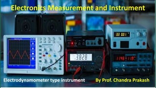
  • 2. Electrodynamometer type Instrument An electrodynamic instrument is a moving-coil instrument in which the operating field is produced, not by a permanent magnet but by another fixed coil. This instrument can be used either as an ammeter or a voltmeter but is generally used as a wattmeter. It can be used for measurement of current, voltage & power for both AC and DC up to 125Hz and with some modifications as power factor & frequency meters. Accuracy is very high and hence can be used in laboratory for calibration of other instruments.
  • 3. The electrodynamometer is a transfer-type instrument. A transfer-type instrument is one that may be calibrated with a dc source and then used without modification to measure AC. This requires the transfer type instruments to have the same accuracy for both DC and AC. If the current is reversed, the field polarity and the polarity of the moving coil reverse at the same time, and the turning force continues in the original direction. Since the reversing the current direction does not reverse the turning force, this type of instruments can be used to measure AC or DC current, voltage, or its major application as a wattmeter for power measurement.
  • 4. Construction The construction of the Electrodynamometer includes fixed coil, moving coil, control, damping, scales, and pointer.
  • 5.
  • 6.
  • 7. Fixed Coils: • The field is produced by a fixed coil. • This coil is divided into two sections to give a more uniform field near the centre and to allow passage of the instrument shaft. • Fixed coils are usually wound with heavy wire carrying the main current in ammeters and watt meters. • The wire is stranded where necessary to reduce eddy current losses in conductors. Moving Coil: • A single element instrument has one moving coil (pressure or voltage coil). • The moving coil is wound either as a self-sustaining coil or else on a non-metallic former. • A metallic former cannot be used as eddy current would be induced in it by the alternating field. • It should be noted that both fixed and moving coils are air cored.
  • 8. Control: • The controlling torque is provided by two control springs. • These springs act as leads to the moving coil. Moving System: • The moving coil is mounted on an aluminum spindle. • The moving system also carries the counter weights and truss type pointer. • Sometimes a suspension may be used in case a high sensitivity is desired. Damping: • Air friction damping is employed for these instruments and is provided by a pair of aluminum vanes, attached to the spindle at the bottom. • These vanes move in sector shaped chambers. • Eddy current damping cannot be used in these instruments as the operating field is very weak (on account of the fact that the coils are air cored) and any introduction of a permanent magnet required for eddy current damping would distort the operating magnetic field of the instrument.
  • 9. Shielding: • The field produced by the fixed coils is somewhat weaker than in other types of instruments. • It is nearly 0.005 to 0.006 Wb/m. • In D.C. Measurements even the earth magnetic field may affect the readings. • Thus it is necessary to shield an electrodynamometer type instrument from the effect of stray magnetic fields. • Air cored electrodynamometer type instruments are protected against external magnetic fields by enclosing them in a casing of high permeability alloy. • This shunts external magnetic fields around the instrument mechanism and minimizes their effects on the indication.
  • 10. Working Principle • Electro-dynamometer type instruments are very similar to PMMC type instrument in which the operating field is produced, not by a permanent magnet but by another fixed coil (usually two fixed air cored coils are used). • The PMMC instrument cannot be used on A.C currents or voltages. If A.C supply is given to these instruments, an alternating torque will be developed. Due to moment of inertia of the moving system, the pointer will not follow the rapidly changing alternating torque and will fail to show any reading. • In order that the instrument should be able to read A.C quantities, the magnetic field in the air gap must change along with the change in current. This principle is used in the electro-dynamometer type instrument.
  • 11. Torque Equation Let, i1 = instantaneous value of current in the fixed coils, (A) i2 = instantaneous value of current in the moving coils, (A) L1 = self-inductance of fixed coils, (H) L2 = self-inductance of moving coil, (H) M = mutual inductance between fixed and moving coils (H)
  • 12. • Flux linkage of Coil 1, ψ1 = L1 i1 + Mi2 Flux linkage of Coil 2, ψ2 = L2 i2 + Mi1 Electrical input energy = e1 i1 dt + e2 i2 dt = i1 dψ1 + i2 dψ2 As e1 = dψ1/dt and e1 = dψ2/dt Electrical input energy = i1 d( L1 i1 + Mi2 )+ i2 d(L2 i2 + Mi1) = i1L1di1 + i1 2dL1 + i1i2dM + i1Mdi2 + i2L2di2 + i2 2dL2 + i1i2dM + i2Mdi1 Since L1 and L2 are constant, therefore dL1 = 0 and dL2 = 0 = i1L1di1 + i1i2dM + i1Mdi2 + i2L2di2 + i1i2dM + i2Mdi1 …………(1) Energy stored in the magnetic field = ½ i1 2L1 + ½ i2 2L2 + i1 i2M Change in energy stored = d(½ i1 2L1 + ½ i2 2L2 + i1 i2M) = i1L1di1+ i2L2di2+ i1Mdi2 + i2Mdi1+ i1i2dM+(i1 2/2)dL1 + (i2 2/2)dL2 But L1 and L2 are constant, therefore dL1 = 0 and dL2 = 0 = i1L1di1+ i2L2di2+ i1Mdi2 + i2Mdi1+ i1i2dM ……(2)
  • 13. From the principle of conservation of energy, Total electrical input energy = Change in energy in energy stored + mechanical energy The mechanical energy can be obtained by subtracting above equations Therefore, mechanical energy = i1 i2dM suppose Td is the deflecting torque and dθ is the change in deflection, then, Mechanical energy = work done = Td dθ Thus we have, Td dθ = i1 i2dM Td = i1 i2 (dM/dθ) controlling torque Tc = kθ where k = spring constant At final steady position Td = Tc I1 I2 (dM/dθ) = kθ Deflection, θ = (I1 I2/k)(dM/dθ)
  • 14. Advantages 1. Can be used for both a.c. as well as d.c. measurements (transfer instrument) 2. Accuracy is very high (can be used for calibration of other instrument). 3. Free from hysteresis and eddy current loss (coils are air cored) 4. As the instrument exhibit square law response the angular deflection of these instrument is directly in terms of RMS value of the a.c parameter under measurement.
  • 15. Disadvantages 1. Low torque to weight ratio hence have low sensitivity. 2. The scale is non-uniform. 3. Highly expensive as compared other instrument for ammeter, voltmeter. therefore used for precision measurement. 4. Frictional losses are high. 5. Higher power consumption as compared to PMMC instrument.
  • 16. Sources of Errors • Error due to low torque to weight ratio. • Error due to temperature change • Error due to eddy current. • Error due to external magnetic field • Error due to frequency