CEx-58 / COx-58 PROFIBUS-DP (PNO) - TR Electronic
CEx-58 / COx-58 PROFIBUS-DP (PNO) - TR Electronic
CEx-58 / COx-58 PROFIBUS-DP (PNO) - TR Electronic

Erfolgreiche ePaper selbst erstellen
Machen Sie aus Ihren PDF Publikationen ein blätterbares Flipbook mit unserer einzigartigen Google optimierten e-Paper Software.
<strong>TR</strong> - ECE - BA - DGB - 0036 - 09 09/20/2011<br />
Rotary<br />
Encoders<br />
Linear Encoders Motion System<br />
D<br />
GB<br />
Seite 2 - <strong>58</strong><br />
Page 59 - 116<br />
CK-<strong>58</strong><br />
CEK-<strong>58</strong><br />
COK-<strong>58</strong><br />
CE-<strong>58</strong><br />
CEV-<strong>58</strong><br />
COV-<strong>58</strong><br />
CH-<strong>58</strong> / CS-<strong>58</strong><br />
CEH-<strong>58</strong> / CES-<strong>58</strong><br />
COH-<strong>58</strong> / COS-<strong>58</strong><br />
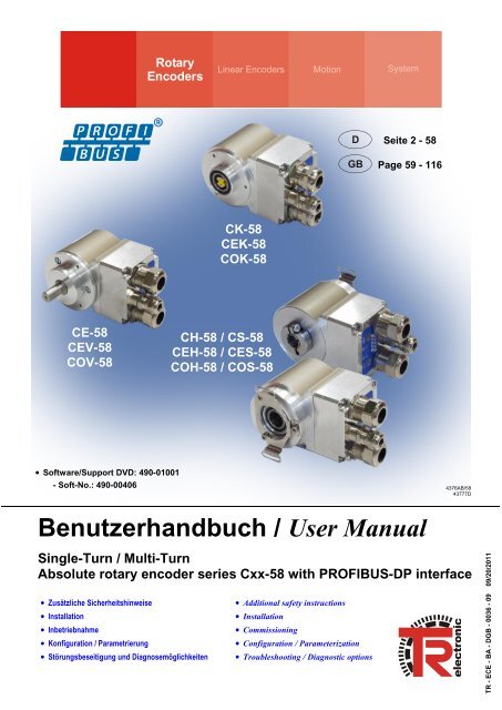
• Software/Support DVD: 490-01001<br />
- Soft-No.: 490-00406<br />
4376AB/<strong>58</strong><br />
43777D<br />
Benutzerhandbuch / User Manual<br />
Single-Turn / Multi-Turn<br />
Absolute rotary encoder series Cxx-<strong>58</strong> with <strong>PROFIBUS</strong>-<strong>DP</strong> interface<br />
• Zusätzliche Sicherheitshinweise<br />
• Installation<br />
• Inbetriebnahme<br />
• Konfiguration / Parametrierung<br />
• Störungsbeseitigung und Diagnosemöglichkeiten<br />
• Additional safety instructions<br />
• Installation<br />
• Commissioning<br />
• Configuration / Parameterization<br />
• Troubleshooting / Diagnostic options
<strong>TR</strong>-<strong>Electronic</strong> GmbH<br />
D-78647 Trossingen<br />
Eglishalde 6<br />
Tel.: (0049) 07425/228-0<br />
Fax: (0049) 07425/228-33<br />
E-mail: info@tr-electronic.de<br />
http://www.tr-electronic.de<br />
Urheberrechtsschutz<br />
Dieses Handbuch, einschließlich den darin enthaltenen Abbildungen, ist<br />
urheberrechtlich geschützt. Drittanwendungen dieses Handbuchs, welche von den<br />
urheberrechtlichen Bestimmungen abweichen, sind verboten. Die Reproduktion,<br />
Übersetzung sowie die elektronische und fotografische Archivierung und<br />
Veränderung bedarf der schriftlichen Genehmigung durch den Hersteller.<br />
Zuwiderhandlungen verpflichten zu Schadenersatz.<br />
Änderungsvorbehalt<br />
Jegliche Änderungen, die dem technischen Fortschritt dienen, vorbehalten.<br />
Dokumenteninformation<br />
Ausgabe-/Rev.-Datum: 09/20/2011<br />
Dokument-/Rev.-Nr.: <strong>TR</strong> - ECE - BA - DGB - 0036 - 09<br />
Dateiname:<br />
<strong>TR</strong>-ECE-BA-DGB-0036-09.DOC<br />
Verfasser:<br />
MÜJ<br />
Schreibweisen<br />
Kursive oder fette Schreibweise steht für den Titel eines Dokuments oder wird zur<br />
Hervorhebung benutzt.<br />
Courier-Schrift zeigt Text an, der auf dem Display bzw. Bildschirm sichtbar ist und<br />
Menüauswahlen von Software.<br />
< > weist auf Tasten der Tastatur Ihres Computers hin<br />
(wie etwa ).<br />
Marken<br />
<strong>PROFIBUS</strong>-<strong>DP</strong> und das <strong>PROFIBUS</strong>-Logo sind eingetragene Warenzeichen der<br />
<strong>PROFIBUS</strong> Nutzerorganisation e.V. (<strong>PNO</strong>)<br />
SIMATIC ist ein eingetragenes Warenzeichen der SIEMENS AG<br />
<strong>TR</strong>-<strong>Electronic</strong> GmbH 2004, All Rights Reserved<br />
Printed in the Federal Republic of Germany<br />
Page 2 of 116 <strong>TR</strong> - ECE - BA - DGB - 0036 - 09 09/20/2011
Inhaltsverzeichnis<br />
Inhaltsverzeichnis<br />
Inhaltsverzeichnis .............................................................................................................................. 3<br />
Änderungs-Index ................................................................................................................................ 6<br />
1 Allgemeines ..................................................................................................................................... 7<br />
1.1 Geltungsbereich ...................................................................................................................... 7<br />
1.2 Verwendete Abkürzungen / Begriffe ....................................................................................... 8<br />
2 Zusätzliche Sicherheitshinweise ................................................................................................... 9<br />
2.1 Symbol- und Hinweis-Definition .............................................................................................. 9<br />
2.2 Ergänzende Hinweise zur bestimmungsgemäßen Verwendung ........................................... 9<br />
2.3 Organisatorische Maßnahmen ............................................................................................... 10<br />
3 Technische Daten ............................................................................................................................ 11<br />
3.1 Elektrische Kenndaten ............................................................................................................ 11<br />
4 <strong>PROFIBUS</strong> Informationen ............................................................................................................... 12<br />
4.1 Kommunikationsprotokoll <strong>DP</strong> ................................................................................................. 12<br />
5 Installation / Inbetriebnahmevorbereitung ................................................................................... 13<br />
5.1 RS485 Übertragungstechnik .................................................................................................. 13<br />
5.2 Variante mit Kabelverschraubungen ...................................................................................... 14<br />
5.2.1 Anschluss ................................................................................................................ 14<br />
5.2.2 Bus-Terminierung ................................................................................................... 15<br />
5.2.3 Bus-Adressierung ................................................................................................... 15<br />
5.2.4 Schirmauflage ......................................................................................................... 15<br />
5.3 Variante mit Steckverbinder ................................................................................................... 18<br />
5.3.1 Anschluss ................................................................................................................ 18<br />
5.3.2 Bus-Terminierung ................................................................................................... 19<br />
5.3.3 Bus-Adressierung ................................................................................................... 19<br />
5.3.4 Schirmauflage ......................................................................................................... 19<br />
6 Inbetriebnahme ................................................................................................................................ 20<br />
6.1 Geräte-Stammdaten-Datei (GSD) .......................................................................................... 20<br />
6.2 <strong>PNO</strong>-Identnummer .................................................................................................................. 20<br />
6.3 Anlauf am <strong>PROFIBUS</strong> ............................................................................................................ 21<br />
6.4 Bus-Statusanzeige .................................................................................................................. 22<br />
Printed in the Federal Republic of Germany<br />
<strong>TR</strong>-<strong>Electronic</strong> GmbH 2004, All Rights Reserved<br />
09/20/2011 <strong>TR</strong> - ECE - BA - DGB - 0036 - 09 Page 3 of 116
Inhaltsverzeichnis<br />
7 Betrieb mit älteren GSD-Datei Ständen ......................................................................................... 23<br />
8 Parametrierung und Konfiguration................................................................................................ 24<br />
8.1 Übersicht ................................................................................................................................. 25<br />
8.1.1 <strong>CEx</strong>-<strong>58</strong>, <strong>TR</strong>09AAAB.GS_ ....................................................................................... 25<br />
8.1.2 <strong>COx</strong>-<strong>58</strong>, <strong>TR</strong>0DAAAB.GS_ ...................................................................................... 26<br />
8.2 <strong>PNO</strong> CLASS 1 16-Bit ............................................................................................................ 27<br />
8.3 <strong>PNO</strong> CLASS 1 32-Bit ............................................................................................................ 27<br />
8.4 <strong>PNO</strong> CLASS 2 16-Bit ............................................................................................................ 28<br />
8.5 <strong>PNO</strong> CLASS 2 32-Bit ............................................................................................................ 29<br />
8.6 <strong>TR</strong>-Mode Position ................................................................................................................... 30<br />
8.7 <strong>TR</strong>-Mode Position + Velocity .................................................................................................. 31<br />
8.8 <strong>TR</strong>-Mode High Resolution ...................................................................................................... 33<br />
8.9 <strong>TR</strong>-Mode High Resolution + Velocity ..................................................................................... 34<br />
8.10 Preset-Justage-Funktion ...................................................................................................... 35<br />
8.11 Beschreibung der Betriebsparameter ................................................................................... 36<br />
8.11.1 Zählrichtung .......................................................................................................... 36<br />
8.11.2 Klasse 2 Funktionalität .......................................................................................... 36<br />
8.11.3 Diagnose Meldemodus ......................................................................................... 36<br />
8.11.4 Inbetriebnahmefunktion ........................................................................................ 37<br />
8.11.5 Kurze Diagnose .................................................................................................... 38<br />
8.11.6 Skalierungsfunktion .............................................................................................. 39<br />
8.11.7 Skalierungsparameter <strong>PNO</strong> CLASS 2 .................................................................. 39<br />
8.11.7.1 Schritte pro Umdrehung ................................................................................................................ 39<br />
8.11.7.2 Messlänge in Schritten .................................................................................................................. 40<br />
8.11.8 Skalierungsparameter <strong>TR</strong>-Modes ......................................................................... 41<br />
8.11.8.1 Messlänge in Schritten .................................................................................................................. 41<br />
8.11.8.2 Umdrehungen Zähler / Umdrehungen Nenner .............................................................................. 42<br />
8.11.9 Code <strong>PROFIBUS</strong>-Schnittstelle ............................................................................. 44<br />
8.11.10 Endschalter unterer und oberer Grenzwert ........................................................ 44<br />
8.11.11 Geschwindigkeit [1/x U/min] ............................................................................... 44<br />
8.11.12 Statusbyte ........................................................................................................... 45<br />
8.12 Konfigurationsbeispiel, SIMATIC Manager V5.1 ................................................................ 46<br />
9 Störungsbeseitigung und Diagnosemöglichkeiten ..................................................................... 50<br />
9.1 Optische Anzeigen .................................................................................................................. 50<br />
9.2 Verwendung der <strong>PROFIBUS</strong> Diagnose ................................................................................. 51<br />
9.2.1 Normdiagnose ......................................................................................................... 51<br />
9.2.1.1 Stationsstatus 1 ............................................................................................................................... 52<br />
9.2.1.2 Stationsstatus 2 ............................................................................................................................... 52<br />
9.2.1.3 Stationsstatus 3 ............................................................................................................................... 52<br />
9.2.1.4 Masteradresse ................................................................................................................................. 53<br />
9.2.1.5 Herstellerkennung ........................................................................................................................... 53<br />
9.2.1.6 Länge (in Byte) der erweiterten Diagnose ....................................................................................... 53<br />
<strong>TR</strong>-<strong>Electronic</strong> GmbH 2004, All Rights Reserved<br />
Printed in the Federal Republic of Germany<br />
Page 4 of 116 <strong>TR</strong> - ECE - BA - DGB - 0036 - 09 09/20/2011
Inhaltsverzeichnis<br />
9.2.2 Erweiterte Diagnose ............................................................................................... 54<br />
9.2.2.1 Alarme ............................................................................................................................................. 54<br />
9.2.2.2 Betriebsstatus .................................................................................................................................. 55<br />
9.2.2.3 Encodertyp ...................................................................................................................................... 55<br />
9.2.2.4 Singleturn Auflösung ....................................................................................................................... 55<br />
9.2.2.5 Anzahl auflösbarer Umdrehungen ................................................................................................... 55<br />
9.2.2.6 Zusätzliche Alarme .......................................................................................................................... 55<br />
9.2.2.7 Unterstützte Alarme ......................................................................................................................... 56<br />
9.2.2.8 Warnungen ...................................................................................................................................... 56<br />
9.2.2.9 Unterstützte Warnungen .................................................................................................................. 56<br />
9.2.2.10 Profil Version ................................................................................................................................. 56<br />
9.2.2.11 Software Version ........................................................................................................................... 57<br />
9.2.2.12 Betriebsstundenzähler ................................................................................................................... 57<br />
9.2.2.13 Offsetwert ...................................................................................................................................... 57<br />
9.2.2.14 Herstellerspezifischer Offsetwert ................................................................................................... 57<br />
9.2.2.15 Anzahl Schritte pro Umdrehung .................................................................................................... 57<br />
9.2.2.16 Messlänge in Schritten .................................................................................................................. 57<br />
9.2.2.17 Seriennummer ............................................................................................................................... 57<br />
9.2.2.18 Herstellerspezifische Diagnosen ................................................................................................... <strong>58</strong><br />
9.3 Sonstige Störungen ................................................................................................................ <strong>58</strong><br />
Printed in the Federal Republic of Germany<br />
<strong>TR</strong>-<strong>Electronic</strong> GmbH 2004, All Rights Reserved<br />
09/20/2011 <strong>TR</strong> - ECE - BA - DGB - 0036 - 09 Page 5 of 116
Änderungs-Index<br />
Änderungs-Index<br />
Änderung Datum Index<br />
Erstausgabe 16.11.04 00<br />
Neue Geräte-Stammdaten-Datei (GSD): <strong>TR</strong>09AAAB.GSD, 07/2005 28.11.05 01<br />
Angaben zur UL / CSA – Zulassung 13.07.06 02<br />
Beschreibung für Endschalterfunktion ergänzt 31.07.06 03<br />
Korrektur Kap. „Optische Anzeigen“:<br />
grüne LED 10 Hz meldet auch einen Positionsfehler<br />
01.04.08 04<br />
Schrittzahl / Umdrehung bis 15 Bit, EMV-Normen angepasst 26.11.09 05<br />
Hinweis für die <strong>TR</strong>-Modes:<br />
Zählrichtung und Justage nicht gleichzeitig ausführbar<br />
Neue Encoder Baureihe: COV-<strong>58</strong>, COK-<strong>58</strong>, COS-<strong>58</strong>, COH-<strong>58</strong><br />
Neue Geräte-Stammdaten-Datei (GSD): <strong>TR</strong>0DAAAB.GSD, 02/2010<br />
06.04.10 06<br />
08.10.10 07<br />
Zusätzliche Hinweise für Auflösungen > 13 Bit 10.01.11 08<br />
Anpassung der Warnhinweise 20.09.11 09<br />
<strong>TR</strong>-<strong>Electronic</strong> GmbH 2004, All Rights Reserved<br />
Printed in the Federal Republic of Germany<br />
Page 6 of 116 <strong>TR</strong> - ECE - BA - DGB - 0036 - 09 09/20/2011
Allgemeines<br />
1 Allgemeines<br />
Das vorliegende schnittstellenspezifische Benutzerhandbuch beinhaltet folgende<br />
Themen:<br />
Ergänzende Sicherheitshinweise zu den bereits in der Montageanleitung<br />
definierten grundlegenden Sicherheitshinweisen<br />
Elektrische Kenndaten<br />
Installation<br />
Inbetriebnahme<br />
Konfiguration / Parametrierung<br />
Störungsbeseitigung und Diagnosemöglichkeiten<br />
Da die Dokumentation modular aufgebaut ist, stellt dieses Benutzerhandbuch eine<br />
Ergänzung zu anderen Dokumentationen wie z.B. Produktdatenblätter,<br />
Maßzeichnungen, Prospekte und der Montageanleitung etc. dar.<br />
Das Benutzerhandbuch kann kundenspezifisch im Lieferumfang enthalten sein, oder<br />
kann auch separat angefordert werden.<br />
1.1 Geltungsbereich<br />
Dieses Benutzerhandbuch gilt ausschließlich für folgende Mess-System-Baureihen<br />
mit <strong>PROFIBUS</strong>-<strong>DP</strong> Schnittstelle:<br />
CE-<strong>58</strong>, CEV-<strong>58</strong>, COV-<strong>58</strong><br />
CH-<strong>58</strong>, CEH-<strong>58</strong>, COH-<strong>58</strong><br />
CS-<strong>58</strong>, CES-<strong>58</strong>, COS-<strong>58</strong><br />
CK-<strong>58</strong>, CEK-<strong>58</strong>, COK-<strong>58</strong><br />
Die Produkte sind durch aufgeklebte Typenschilder gekennzeichnet und sind<br />
Bestandteil einer Anlage.<br />
Es gelten somit zusammen folgende Dokumentationen:<br />
anlagenspezifische Betriebsanleitungen des Betreibers,<br />
dieses Benutzerhandbuch,<br />
und die bei der Lieferung beiliegende<br />
Montageanleitung <strong>TR</strong>-ECE-BA-DGB-0035<br />
Printed in the Federal Republic of Germany<br />
<strong>TR</strong>-<strong>Electronic</strong> GmbH 2004, All Rights Reserved<br />
09/20/2011 <strong>TR</strong> - ECE - BA - DGB - 0036 - 09 Page 7 of 116
Allgemeines<br />
1.2 Verwendete Abkürzungen / Begriffe<br />
CE, CEV<br />
COV<br />
CK, CEK<br />
COK<br />
CS, CES<br />
COS<br />
CH, CEH<br />
COH<br />
CW<br />
CCW<br />
DDLM<br />
<strong>DP</strong><br />
EMV<br />
GSD<br />
<strong>PNO</strong><br />
<strong>PROFIBUS</strong><br />
Absolut-Encoder mit optischer Abtastung<br />
Ausführung mit Vollwelle<br />
15 Bit Auflösung,<br />
Absolut-Encoder mit optischer Abtastung > 15 Bit Auflösung,<br />
Ausführung mit Vollwelle<br />
Absolut-Encoder mit optischer Abtastung<br />
Ausführung mit Kupplung<br />
15 Bit Auflösung,<br />
Absolut-Encoder mit optischer Abtastung > 15 Bit Auflösung,<br />
Ausführung mit Kupplung<br />
Absolut-Encoder mit optischer Abtastung<br />
Ausführung mit Sackloch<br />
15 Bit Auflösung,<br />
Absolut-Encoder mit optischer Abtastung > 15 Bit Auflösung,<br />
Ausführung mit Sackloch<br />
Absolut-Encoder mit optischer Abtastung<br />
Ausführung mit Hohlwelle<br />
15 Bit Auflösung,<br />
Absolut-Encoder mit optischer Abtastung > 15 Bit Auflösung,<br />
Ausführung mit Hohlwelle<br />
im Uhrzeigersinn (clockwise)<br />
entgegen dem Uhrzeigersinn (counterclockwise)<br />
Direct Data Link Mapper, Schnittstelle zwischen <strong>PROFIBUS</strong>-<strong>DP</strong><br />
Funktionen und Mess-System Software<br />
Dezentralized Periphery (Dezentrale Peripherie)<br />
Elektro-Magnetische-Verträglichkeit<br />
Geräte-Stammdaten-Datei<br />
<strong>PROFIBUS</strong> Nutzerorganisation e.V.<br />
herstellerunabhängiger, offener Feldbusstandard<br />
<strong>TR</strong>-<strong>Electronic</strong> GmbH 2004, All Rights Reserved<br />
Printed in the Federal Republic of Germany<br />
Page 8 of 116 <strong>TR</strong> - ECE - BA - DGB - 0036 - 09 09/20/2011
Zusätzliche Sicherheitshinweise<br />
2 Zusätzliche Sicherheitshinweise<br />
2.1 Symbol- und Hinweis-Definition<br />
bedeutet, dass Tod oder schwere Körperverletzung eintreten<br />
kann, wenn die entsprechenden Vorsichtsmaßnahmen<br />
nicht getroffen werden.<br />
bedeutet, dass eine leichte Körperverletzung eintreten kann,<br />
wenn die entsprechenden Vorsichtsmaßnahmen nicht<br />
getroffen werden.<br />
bedeutet, dass ein Sachschaden eintreten kann, wenn die<br />
entsprechenden Vorsichtsmaßnahmen nicht getroffen<br />
werden.<br />
bezeichnet wichtige Informationen bzw. Merkmale und<br />
Anwendungstipps des verwendeten Produkts.<br />
2.2 Ergänzende Hinweise zur bestimmungsgemäßen Verwendung<br />
Das Mess-System ist ausgelegt für den Betrieb an <strong>PROFIBUS</strong>-<strong>DP</strong> Netzwerken nach<br />
den europäischen Normen EN 50170 und EN 50254 bis max. 12 MBaud. Die<br />
Parametrierung und die Gerätediagnose erfolgen durch den <strong>PROFIBUS</strong>-Master nach<br />
dem Profil für Encoder Version 1.1 der <strong>PROFIBUS</strong> Nutzerorganisation (<strong>PNO</strong>).<br />
Die technischen Richtlinien zum Aufbau des <strong>PROFIBUS</strong>-<strong>DP</strong> Netzwerks der<br />
<strong>PROFIBUS</strong> Nutzerorganisation sind für einen sicheren Betrieb zwingend einzuhalten.<br />
Zur bestimmungsgemäßen Verwendung gehört auch:<br />
das Beachten aller Hinweise aus diesem Benutzerhandbuch,<br />
das Beachten der Montageanleitung, insbesondere das dort enthaltene<br />
Kapitel "Grundlegende Sicherheitshinweise" muss vor Arbeitsbeginn gelesen<br />
und verstanden worden sein<br />
Printed in the Federal Republic of Germany<br />
<strong>TR</strong>-<strong>Electronic</strong> GmbH 2004, All Rights Reserved<br />
09/20/2011 <strong>TR</strong> - ECE - BA - DGB - 0036 - 09 Page 9 of 116
Zusätzliche Sicherheitshinweise<br />
2.3 Organisatorische Maßnahmen<br />
Dieses Benutzerhandbuch muss ständig am Einsatzort des Mess-Systems<br />
griffbereit aufbewahrt werden.<br />
Das mit Tätigkeiten am Mess-System beauftragte Personal muss vor Arbeitsbeginn<br />
- die Montageanleitung, insbesondere das Kapitel "Grundlegende<br />
Sicherheitshinweise",<br />
- und dieses Benutzerhandbuch, insbesondere das Kapitel "Zusätzliche<br />
Sicherheitshinweise",<br />
gelesen und verstanden haben.<br />
Dies gilt in besonderem Maße für nur gelegentlich, z. B. bei der<br />
Parametrierung des Mess-Systems, tätig werdendes Personal.<br />
<strong>TR</strong>-<strong>Electronic</strong> GmbH 2004, All Rights Reserved<br />
Printed in the Federal Republic of Germany<br />
Page 10 of 116 <strong>TR</strong> - ECE - BA - DGB - 0036 - 09 09/20/2011
Technische Daten<br />
3 Technische Daten<br />
3.1 Elektrische Kenndaten<br />
Versorgungsspannung: .................................... 11…27 VDC, paarweise verdrillt und geschirmt<br />
Bei UL / CSA-Zulassung ............................ Nach NEC Klasse 2; 24 VDC (11-27 VDC)<br />
Stromaufnahme ohne Last: .............................. < 350 mA bei 11 VDC, < 150 mA bei 27 VDC<br />
Gesamtauflösung<br />
<strong>CEx</strong>-<strong>58</strong>: ....................................................... 33 Bit, Datenbreite für Istposition auf dem Bus: 25 Bit<br />
<strong>COx</strong>-<strong>58</strong>: ...................................................... 36 Bit, Datenbreite für Istposition auf dem Bus: 29 Bit<br />
* Schrittzahl / Umdrehung<br />
<strong>CEx</strong>-<strong>58</strong>, Standard: ...................................... 8.192<br />
<strong>CEx</strong>-<strong>58</strong>, erweitert: ....................................... 32.768<br />
<strong>COx</strong>-<strong>58</strong>: ...................................................... 262.144<br />
* Anzahl Umdrehungen<br />
<strong>CEx</strong>-<strong>58</strong>, Standard: ...................................... 4.096 Umdrehungen<br />
<strong>CEx</strong>-<strong>58</strong>, erweitert: ....................................... 256.000 Umdrehungen<br />
<strong>COx</strong>-<strong>58</strong>: ...................................................... 262.144 Umdrehungen<br />
Ausgabecode<br />
* <strong>CEx</strong>-<strong>58</strong>: .................................................... Binär, Gray, gekappter Gray<br />
<strong>COx</strong>-<strong>58</strong>: .................................................... Binär<br />
Standardbaudraten: .......................................... 9.6 kBaud bis 12 MBaud<br />
Zykluszeit: .......................................................... 250 µs<br />
Stationsadressen: ............................................. 3 – 99, einstellbar über BCD-Drehschalter<br />
<strong>PROFIBUS</strong>-<strong>DP</strong> Norm: ........................................ IEC 611<strong>58</strong>, IEC 61784<br />
Übertragung: ...................................................... RS485, verdrilltes und geschirmtes Kupferkabel mit<br />
einem Leiterpaar (Kabeltyp A)<br />
Besondere Merkmale: ....................................... Die Programmierung erfolgt über das<br />
Parametriertelegramm beim Anlaufen des Mess-Systems<br />
oder des <strong>PROFIBUS</strong>-<strong>DP</strong> Masters<br />
EMV<br />
Störfestigkeit: .............................................. DIN EN 61000-6-2: 2006<br />
Störaussendung: ........................................ DIN EN 61000-6-3: 2007<br />
* parametrierbar über den <strong>PROFIBUS</strong>-<strong>DP</strong><br />
Printed in the Federal Republic of Germany<br />
<strong>TR</strong>-<strong>Electronic</strong> GmbH 2004, All Rights Reserved<br />
09/20/2011 <strong>TR</strong> - ECE - BA - DGB - 0036 - 09 Page 11 of 116
<strong>PROFIBUS</strong> Informationen<br />
4 <strong>PROFIBUS</strong> Informationen<br />
<strong>PROFIBUS</strong> ist ein durchgängiges, offenes, digitales Kommunikationssystem mit<br />
breitem Anwendungsbereich vor allem in der Fertigungs- und<br />
Prozessautomatisierung. <strong>PROFIBUS</strong> ist für schnelle, zeitkritische und für komplexe<br />
Kommunikationsaufgaben geeignet.<br />
Die Kommunikation von <strong>PROFIBUS</strong> ist in den internationalen Normen IEC 611<strong>58</strong> und<br />
IEC 61784 verankert. Die Anwendungs- und Engineeringaspekte sind in Richtlinien<br />
der <strong>PROFIBUS</strong> Nutzerorganisation festgelegt. Damit werden die<br />
Anwenderforderungen nach Herstellerunabhängigkeit und Offenheit erfüllt und die<br />
Kommunikation untereinander von Geräten verschiedener Hersteller ohne<br />
Anpassungen an den Geräten garantiert.<br />
Für Encoder wurde von der <strong>PROFIBUS</strong> Nutzerorganisation ein spezielles Profil<br />
verabschiedet. Das Profil beschreibt die Ankopplung von Dreh-, Winkel- und Linear-<br />
Encodern mit Singleturn- oder Multiturn-Auflösung an <strong>DP</strong>. Zwei Geräteklassen<br />
definieren Basisfunktionen und Zusatzfunktionen, wie z. B. Skalierung,<br />
Alarmbehandlung und Diagnose.<br />
Die Mess-Systeme unterstützen neben denen im Profil definierten Geräte-Klassen 1<br />
und 2, noch zusätzliche <strong>TR</strong>-spezifische Funktionen.<br />
Eine Druckschrift des Encoder-Profils (Bestell-Nr.: 3.062) und weiterführende<br />
Informationen zum <strong>PROFIBUS</strong> ist bei der Geschäftsstelle der <strong>PROFIBUS</strong>-<br />
Nutzerorganisation erhältlich:<br />
<strong>PROFIBUS</strong> Nutzerorganisation e.V.,<br />
Haid-und-Neu-Str. 7,<br />
D-76131 Karlsruhe,<br />
http://www.profibus.com/<br />
Tel.: ++ 49 (0) 721 / 96 <strong>58</strong> 590<br />
Fax: ++ 49 (0) 721 / 96 <strong>58</strong> <strong>58</strong>9<br />
e-mail: mailto:germany@profibus.com<br />
4.1 Kommunikationsprotokoll <strong>DP</strong><br />
Die Mess-Systeme unterstützen das Kommunikationsprotokoll <strong>DP</strong>, welches für einen<br />
schnellen Datenaustausch in der Feldebene konzipiert ist. Die Grundfunktionalität<br />
wird durch die Leistungsstufe V0 festgelegt. Dazu gehören der zyklische<br />
Datenaustausch sowie die stations-, modul- und kanalspezifische Diagnose.<br />
<strong>TR</strong>-<strong>Electronic</strong> GmbH 2004, All Rights Reserved<br />
Printed in the Federal Republic of Germany<br />
Page 12 of 116 <strong>TR</strong> - ECE - BA - DGB - 0036 - 09 09/20/2011
Installation / Inbetriebnahmevorbereitung<br />
5 Installation / Inbetriebnahmevorbereitung<br />
5.1 RS485 Übertragungstechnik<br />
Alle Geräte werden in einer Busstruktur (Linie) angeschlossen. In einem Segment<br />
können bis zu 32 Teilnehmer (Master oder Slaves) zusammengeschaltet werden.<br />
Am Anfang und am Ende jedes Segments wird der Bus durch einen aktiven<br />
Busabschluss abgeschlossen. Für einen störungsfreien Betrieb muss sichergestellt<br />
werden, dass die beiden Busabschlüsse immer mit Spannung versorgt werden. Der<br />
Busabschluss kann in der Mess-System-Anschlusshaube zugeschaltet werden.<br />
Bei mehr als 32 Teilnehmern oder zur Vergrößerung der Netzausdehnung müssen<br />
Repeater (Signalverstärker) eingesetzt werden, um die einzelnen Bussegmente zu<br />
verbinden.<br />
Alle verwendeten Leitungen müssen entsprechend der <strong>PROFIBUS</strong>-Spezifikation für<br />
die Kupfer-Datenadern folgende Parameter erfüllen:<br />
Parameter<br />
Leitungstyp A<br />
Wellenwiderstand in<br />
135...165 bei einer Frequenz von 3...20 MHz<br />
Betriebskapazität (pF/m) 30<br />
Schleifenwiderstand ( /km) 110<br />
Aderndurchmesser (mm) > 0,64<br />
Aderquerschnitt (mm²) > 0,34<br />
Die Übertragungsgeschwindigkeit ist beim <strong>PROFIBUS</strong> im Bereich zwischen 9.6 kBit/s<br />
und 12 Mbit/s wählbar und wird vom Mess-System automatisch erkannt. Sie wird bei<br />
der Inbetriebnahme des Systems einheitlich für alle Geräte am Bus ausgewählt.<br />
Reichweite in Abhängigkeit der Übertragungsgeschwindigkeit für Kabeltyp A:<br />
Baudrate (kbits/s) 9.6 19.2 93.75 187.5 500 1500 12000<br />
Reichweite / Segment 1200 m 1200 m 1200 m 1000 m 400 m 200 m 100 m<br />
Um eine hohe Störfestigkeit des Systems gegen elektromagnetische Störstrahlungen<br />
zu erzielen, muss eine geschirmte Datenleitung verwendet werden. Der Schirm sollte<br />
möglichst beidseitig und gut leitend über großflächige Schirmschellen an Schutzerde<br />
angeschlossen werden. Weiterhin ist zu beachten, dass die Datenleitung möglichst<br />
separat von allen starkstromführenden Kabeln verlegt wird. Bei Datenraten<br />
1,5 Mbit/s sind Stichleitungen unbedingt zu vermeiden.<br />
Um einen sicheren und störungsfreien Betrieb zu gewährleisten, sind die <strong>PROFIBUS</strong>-<br />
Richtlinien und sonstige einschlägige Normen und Richtlinien zu beachten!<br />
Insbesondere sind die EMV-Richtlinie sowie die Schirmungs- und Erdungsrichtlinien in<br />
den jeweils gültigen Fassungen zu beachten!<br />
Printed in the Federal Republic of Germany<br />
<strong>TR</strong>-<strong>Electronic</strong> GmbH 2004, All Rights Reserved<br />
09/20/2011 <strong>TR</strong> - ECE - BA - DGB - 0036 - 09 Page 13 of 116
0 1 2 3 4 5 6 7 8 9<br />
0 1 2 3 4 5 6 7 8 9<br />
0 1 2 3 4 5 6 7 8 9<br />
0 1 2 3 4 5 6 7 8 9<br />
0 1 2 3 4 5 6 7 8 9<br />
0 1 2 3 4 5 6 7 8 9<br />
Installation / Inbetriebnahmevorbereitung<br />
5.2 Variante mit Kabelverschraubungen<br />
5.2.1 Anschluss<br />
Um den Anschluss vornehmen zu können, muss zuerst die Anschlusshaube vom<br />
Mess-System abgenommen werden.<br />
Dazu werden die vier Schrauben (A) gelöst und die Haube abgezogen.<br />
1<br />
1<br />
A<br />
Abbildung 1: Abnehmen der Anschlusshaube<br />
<strong>PROFIBUS</strong>_IN<br />
Pin 1<br />
Pin 2<br />
Pin 3<br />
Pin 4<br />
<strong>PROFIBUS</strong> Data A<br />
<strong>PROFIBUS</strong> Data B<br />
Versorgungsspannung, 11-27 VDC<br />
0 V, GND<br />
IN<br />
1<br />
<strong>PROFIBUS</strong>_OUT<br />
Pin 1<br />
Pin 2<br />
Pin 3<br />
Pin 4<br />
<strong>PROFIBUS</strong> Data A<br />
<strong>PROFIBUS</strong> Data B<br />
Versorgungsspannung, 11-27 VDC<br />
0 V, GND<br />
1<br />
OUT<br />
Die Klemmen für die Versorgungsspannung (Pin 3 / Pin 4) sind intern miteinander<br />
verbunden und können sowohl als Einspeisung, als auch für die Versorgung des<br />
nachfolgenden Teilnehmers verwendet werden.<br />
<strong>TR</strong>-<strong>Electronic</strong> GmbH 2004, All Rights Reserved<br />
Printed in the Federal Republic of Germany<br />
Page 14 of 116 <strong>TR</strong> - ECE - BA - DGB - 0036 - 09 09/20/2011
50 1 2 3 4<br />
50 1 2 3 4<br />
Installation / Inbetriebnahmevorbereitung<br />
5.2.2 Bus-Terminierung<br />
ON<br />
Ist das Mess-System der letzte Teilnehmer<br />
im <strong>PROFIBUS</strong>-Segment, ist der<br />
Bus durch den Terminierungsschalter =<br />
ON abzuschließen. In diesem Zustand<br />
wird der weiterführende <strong>PROFIBUS</strong><br />
abgekoppelt.<br />
6 7 8 9<br />
6 7 8 9<br />
OFF<br />
5.2.3 Bus-Adressierung<br />
Gültige <strong>PROFIBUS</strong>-Adressen: 3 – 99<br />
10 0 : Einstellung der 1er-Stelle<br />
10 1 : Einstellung der 10er-Stelle<br />
Bei Einstellung einer ungültigen<br />
Stationsadresse läuft das Gerät nicht an.<br />
6 7 8 9<br />
50 1 2 3 4<br />
10 1 10 0<br />
6 7 8 9<br />
50 1 2 3 4<br />
5.2.4 Schirmauflage<br />
Die Schirmauflage erfolgt durch spezielle EMV-gerechte Kabelverschraubungen, bei<br />
denen die Kabelschirmung innen aufgelegt werden kann.<br />
<strong>PROFIBUS</strong>-Kabel vorbereiten (z.B. 2-adrig)<br />
ca. 80 mm<br />
X mm 5mm<br />
Das Maß "X" ist abhängig vom Typ und Größe der verwendeten Kabelverschraubung.<br />
Printed in the Federal Republic of Germany<br />
<strong>TR</strong>-<strong>Electronic</strong> GmbH 2004, All Rights Reserved<br />
09/20/2011 <strong>TR</strong> - ECE - BA - DGB - 0036 - 09 Page 15 of 116
Installation / Inbetriebnahmevorbereitung<br />
Montage für Kabelverschraubung, Variante A<br />
Pos. 1 Überwurfmutter<br />
Pos. 2 Dichteinsatz<br />
Pos. 3 Kontakthülse<br />
Pos. 5 Einschraubstutzen<br />
1. Schirmumflechtung / Schirmfolie auf Maß "X" zurückschneiden.<br />
2. Überwurfmutter (1) und Dichteinsatz / Kontakthülse (2) + (3) auf das Kabel<br />
aufschieben.<br />
3. Die Schirmumflechtung / Schirmfolie um ca. 90° umbiegen (4).<br />
4. Dichteinsatz / Kontakthülse (2) + (3) bis an die Schirmumflechtung /<br />
Schirmfolie schieben.<br />
5. Einschraubstutzen (5) am Gehäuse montieren.<br />
6. Dichteinsatz / Kontakthülse (2) + (3) in Einschraubstutzen (5) bündig<br />
zusammen stecken.<br />
7. Überwurfmutter (1) mit Einschraubstutzen (5) verschrauben.<br />
<strong>TR</strong>-<strong>Electronic</strong> GmbH 2004, All Rights Reserved<br />
Printed in the Federal Republic of Germany<br />
Page 16 of 116 <strong>TR</strong> - ECE - BA - DGB - 0036 - 09 09/20/2011
Installation / Inbetriebnahmevorbereitung<br />
Montage für Kabelverschraubung, Variante B<br />
Pos. 1 Überwurfmutter<br />
Pos. 2 Klemmeinsatz<br />
Pos. 3 innerer O-Ring<br />
Pos. 4 Einschraubstutzen<br />
1. Schirmumflechtung / Schirmfolie auf Maß "X" + 2mm zurückschneiden.<br />
2. Überwurfmutter (1) und Klemmeneinsatz (2) auf das Kabel aufschieben.<br />
3. Die Schirmumflechtung / Schirmfolie um ca. 90° umbiegen.<br />
4. Klemmeinsatz (2) bis an die Schirmumflechtung / Schirmfolie schieben und<br />
das Geflecht um den Klemmeinsatz (2) zurückstülpen, so dass das Geflecht<br />
über den inneren O-Ring (3) geht, und nicht über dem zylindrischen Teil<br />
oder den Verdrehungsstegen liegt.<br />
5. Einschraubstutzen (4) am Gehäuse montieren.<br />
6. Klemmeinsatz (2) in Einschraubstutzen (4) einführen, so dass die<br />
Verdrehungsstege in die im Einschraubstutzen (4) vorgesehenen<br />
Längsnuten passen.<br />
7. Überwurfmutter (1) mit Einschraubstutzen (4) verschrauben.<br />
1<br />
2<br />
3<br />
4<br />
Printed in the Federal Republic of Germany<br />
<strong>TR</strong>-<strong>Electronic</strong> GmbH 2004, All Rights Reserved<br />
09/20/2011 <strong>TR</strong> - ECE - BA - DGB - 0036 - 09 Page 17 of 116
Installation / Inbetriebnahmevorbereitung<br />
5.3 Variante mit Steckverbinder<br />
5.3.1 Anschluss<br />
Abbildung 2: Variante mit Steckverbinder<br />
X1, <strong>PROFIBUS</strong>_IN Flanschstecker, M12x1-5 pol. B-kodiert<br />
Pin 1<br />
Pin 2<br />
Pin 3<br />
Pin 4<br />
Pin 5<br />
N.C.<br />
<strong>PROFIBUS</strong>, Data A<br />
N.C.<br />
<strong>PROFIBUS</strong>, Data B<br />
N.C.<br />
X2, <strong>PROFIBUS</strong>_OUT Flanschdose, M12x1-5 pol. B-kodiert<br />
Pin 1<br />
Pin 2<br />
Pin 3<br />
Pin 4<br />
Pin 5<br />
N.C.<br />
<strong>PROFIBUS</strong>, Data A<br />
N.C.<br />
<strong>PROFIBUS</strong>, Data B<br />
N.C.<br />
X3, Versorgung Flanschstecker, M8x1-4 pol.<br />
Pin 1<br />
Pin 2<br />
Pin 3<br />
Pin 4<br />
Versorgungsspannung, 11-27 V DC<br />
N.C.<br />
0 V, GND<br />
N.C.<br />
Gegenstecker zu X1<br />
Gegenstecker zu X2<br />
Winkeldose BINDER: 99-1436-820-05<br />
Kabeldose BINDER: 99-1436-810-05<br />
Kabeldose LUMBERG: 0976 PFC 101<br />
Kabeldose PHOENIX CONTACT: 15 07 77 7<br />
Winkelstecker BINDER: 99-1437-820-05<br />
Kabelstecker BINDER: 99-1437-810-05<br />
Kabelstecker LUMBERG: 0976 PMC 101<br />
Kabelstecker PHOENIX CONTACT: 15 07 76 4<br />
<strong>TR</strong>-<strong>Electronic</strong> GmbH 2004, All Rights Reserved<br />
Printed in the Federal Republic of Germany<br />
Page 18 of 116 <strong>TR</strong> - ECE - BA - DGB - 0036 - 09 09/20/2011
Installation / Inbetriebnahmevorbereitung<br />
5.3.2 Bus-Terminierung<br />
Ist das Mess-System der letzte Teilnehmer<br />
im <strong>PROFIBUS</strong>-Segment, ist der<br />
Bus durch den Terminierungsschalter =<br />
ON abzuschließen. In diesem Zustand<br />
wird der weiterführende <strong>PROFIBUS</strong><br />
abgekoppelt.<br />
5.3.3 Bus-Adressierung<br />
Gültige <strong>PROFIBUS</strong>-Adressen: 3 – 99<br />
10 0 : Einstellung der 1er-Stelle<br />
10 1 : Einstellung der 10er-Stelle<br />
Bei Einstellung einer ungültigen<br />
Stationsadresse läuft das Gerät nicht.<br />
5.3.4 Schirmauflage<br />
Die Schirmung ist großflächig auf den Gegenstecker aufzulegen.<br />
Printed in the Federal Republic of Germany<br />
<strong>TR</strong>-<strong>Electronic</strong> GmbH 2004, All Rights Reserved<br />
09/20/2011 <strong>TR</strong> - ECE - BA - DGB - 0036 - 09 Page 19 of 116
Inbetriebnahme<br />
6 Inbetriebnahme<br />
6.1 Geräte-Stammdaten-Datei (GSD)<br />
Um für <strong>PROFIBUS</strong> eine einfache Plug-and-Play Konfiguration zu erreichen, wurden<br />
die charakteristischen Kommunikationsmerkmale von <strong>PROFIBUS</strong>-Geräten in Form<br />
eines elektronischen Gerätedatenblatts (Gerätestammdaten- Datei, GSD-Datei)<br />
festgelegt.<br />
Durch das festgelegte Dateiformat kann das Projektierungssystem die<br />
Gerätestammdaten des <strong>PROFIBUS</strong>-Mess-Systems einfach einlesen und bei der<br />
Konfiguration des Bussystems automatisch berücksichtigen.<br />
Die GSD-Datei ist Bestandteil des Mess-Systems und hat den Dateinamen<br />
●<br />
<strong>CEx</strong>-<strong>58</strong>: "<strong>TR</strong>09AAAB.GSG" (Deutsch)<br />
● <strong>COx</strong>-<strong>58</strong>: "<strong>TR</strong>0DAAAB.GSD" (Deutsch.<br />
Zum Mess-System gehören weiterhin noch zwei Bitmap Dateien mit Namen<br />
"Traaab5n.bmp" und "Traaab5s.bmp", die das Mess-System zum einen im<br />
Normalbetrieb, und zum anderen mit Störung zeigt.<br />
Die Dateien befinden sich auf der Software/Support DVD:<br />
Art.-Nr.: 490-01001, Soft-Nr.: 490-00406.<br />
System Konfiguration<br />
<strong>PROFIBUS</strong><br />
Konfigurator<br />
SPS<br />
Elektronische Gerätedatenblätter (GSD-Dateien)<br />
<strong>PROFIBUS</strong><br />
Abbildung 3: GSD für die Konfiguration<br />
6.2 <strong>PNO</strong>-Identnummer<br />
Jeder <strong>PROFIBUS</strong> Slave und jeder Master Klasse 1 muss eine Identnummer haben.<br />
Sie wird benötigt, damit ein Master ohne signifikanten Protokolloverhead die Typen<br />
der angeschlossenen Geräte identifizieren kann. Der Master vergleicht die<br />
Identnummern der angeschlossenen Geräte mit den Identnummern in den vom<br />
Projektierungstool vorgegebenen Projektierungsdaten. Der Nutzdatentransfer wird nur<br />
dann begonnen, wenn die richtigen Gerätetypen mit den richtigen Stationsadressen<br />
am Bus angeschlossen wurden. Dadurch wird eine hohe Sicherheit gegenüber<br />
Projektierungsfehlern erreicht.<br />
Das Mess-System hat die <strong>PNO</strong>-Identnummer AAAB (Hex). Diese Nummer ist<br />
reserviert und bei der <strong>PNO</strong> hinterlegt.<br />
<strong>TR</strong>-<strong>Electronic</strong> GmbH 2004, All Rights Reserved<br />
Printed in the Federal Republic of Germany<br />
Page 20 of 116 <strong>TR</strong> - ECE - BA - DGB - 0036 - 09 09/20/2011
Inbetriebnahme<br />
6.3 Anlauf am <strong>PROFIBUS</strong><br />
Bevor das Mess-System in den Nutzdatenverkehr (Data_Exchange) aufgenommen<br />
werden kann, muss der Master im Hochlauf das Mess-System zuerst initialisieren.<br />
Der dabei entstehende Datenverkehr zwischen dem Master und dem Mess-System<br />
(Slave) gliedert sich in die Parametrierungs-, Konfigurierungs- und<br />
Datentransferphase.<br />
Hierbei wird überprüft, ob die projektierte Sollkonfiguration mit der tatsächlichen<br />
Gerätekonfiguration übereinstimmt. Bei dieser Überprüfung müssen der Gerätetyp,<br />
die Format- und Längeninformationen sowie die Anzahl der Ein- und Ausgänge<br />
übereinstimmen. Der Benutzer erhält dadurch einen zuverlässigen Schutz gegen<br />
Parametrierungsfehler.<br />
Konnte die Überprüfung fehlerfrei ausgeführt werden, wird in den so genannten<br />
DDLM_Data_Exchange – Modus umgeschaltet. In diesem Modus überträgt das<br />
Mess-System z.B. seine Istposition und es kann die Preset-Justage-Funktion<br />
ausgeführt werden.<br />
<strong>DP</strong> Watchdog<br />
Power On/<br />
Reset<br />
Initialisierung<br />
WPRM<br />
Parameter nicht ok<br />
Konfiguration nicht ok<br />
Parameter ok<br />
Unlock<br />
Konfiguration nicht ok<br />
Parameter nicht ok<br />
falsche Output Länge<br />
WCFG<br />
Konfiguration ok<br />
DXCHG<br />
WPRM = Wait Parameter<br />
WCFG = Wait Configuration<br />
DXCHG = Data Exchange<br />
Parameter und Konfiguration ok<br />
Outputs Empfänger/<br />
Inputs zurückgeben<br />
Abbildung 4: <strong>DP</strong>-Slave Initialisierung<br />
Printed in the Federal Republic of Germany<br />
<strong>TR</strong>-<strong>Electronic</strong> GmbH 2004, All Rights Reserved<br />
09/20/2011 <strong>TR</strong> - ECE - BA - DGB - 0036 - 09 Page 21 of 116
Inbetriebnahme<br />
6.4 Bus-Statusanzeige<br />
Das Mess-System verfügt über zwei LEDs in der Anschlusshaube. Eine rote LED<br />
(Bus Fail) zur Anzeige von Fehlern und eine grüne LED (Bus Run) zur Anzeige der<br />
Statusinformation.<br />
Beim Anlaufen des Mess-Systems blinken beide LEDs kurz auf. Danach hängt die<br />
Anzeige vom Betriebszustand des Mess-Systems ab.<br />
Variante mit Kabelverschraubungen<br />
Variante mit Steckverbinder<br />
= AN<br />
= AUS<br />
= 1 Hz<br />
= 10 Hz<br />
LED, grün<br />
betriebsbereit<br />
Versorgung fehlt, Hardwarefehler<br />
Bus Run<br />
Parametrier- oder Konfigurationsfehler in <strong>PNO</strong>-kompatibler<br />
Sollkonfiguration. Die Daten wurden korrigiert.<br />
nicht behebbarer Parametrier- oder Konfigurationsfehler<br />
LED, rot<br />
kein Fehler, Bus im Zyklus<br />
Bus Fail<br />
Mess-System wird vom Master nicht angesprochen,<br />
kein Data-Exchange<br />
nicht behebbare Mess-System Störung<br />
Entsprechende Maßnahmen im Fehlerfall siehe Kapitel „Störungsbeseitigung und<br />
Diagnosemöglichkeiten“, Seite 50.<br />
<strong>TR</strong>-<strong>Electronic</strong> GmbH 2004, All Rights Reserved<br />
Printed in the Federal Republic of Germany<br />
Page 22 of 116 <strong>TR</strong> - ECE - BA - DGB - 0036 - 09 09/20/2011
Betrieb mit älteren GSD-Datei Ständen<br />
7 Betrieb mit älteren GSD-Datei Ständen<br />
GSD-Datei:<br />
<strong>TR</strong>05AAAB.GSD<br />
Stand: 14.09.2001<br />
Gerätetyp:<br />
CX-65, CX-<strong>58</strong><br />
Firmware-Stand: 4.x<br />
Hardwarekatalog-Eintrag: <strong>TR</strong> CE65M <strong>DP</strong> V4.0+<br />
Kommentar:<br />
Grundversion<br />
GSD-Datei:<br />
<strong>TR</strong>09AAAB.GSD<br />
Stand: 11.07.2005<br />
Gerätetyp:<br />
Firmware-Stand:<br />
Hardwarekatalog-Eintrag:<br />
Kommentar:<br />
Kompatibilität zu<br />
<strong>TR</strong>05AAAB.GSD:<br />
65er, <strong>58</strong>er<br />
4376AA_01 und 4376AB_01<br />
<strong>TR</strong> CE<strong>58</strong>_65M <strong>DP</strong> V1<br />
Erweiterung der Getriebeparameter in den <strong>TR</strong>-Modes<br />
„Position“ und „Position+Velocity“:<br />
Untergrenze Zähler: 1<br />
Obergrenze Zähler: 256.000<br />
Untergrenze Nenner: 1<br />
Obergrenze Nenner: 16.384<br />
Einschränkungen:<br />
Ist die Anzahl der Umdrehungen keine 2-er<br />
Potenz oder >4096, kann, falls mehr als 512<br />
Umdrehungen im stromlosen Zustand<br />
ausgeführt werden, der Nullpunkt des Multi-<br />
Turn Mess-Systems verloren gehen!<br />
Einschränkungen:<br />
Untergrenze Zähler: 1<br />
Obergrenze Zähler: 62.464<br />
Untergrenze Nenner: 1<br />
Obergrenze Nenner: 99<br />
Printed in the Federal Republic of Germany<br />
<strong>TR</strong>-<strong>Electronic</strong> GmbH 2004, All Rights Reserved<br />
09/20/2011 <strong>TR</strong> - ECE - BA - DGB - 0036 - 09 Page 23 of 116
Parametrierung und Konfiguration<br />
8 Parametrierung und Konfiguration<br />
Parametrierung<br />
Parametrierung bedeutet, einem <strong>PROFIBUS</strong>-<strong>DP</strong> Slave vor dem Eintritt in den zyklischen<br />
Austausch von Prozessdaten bestimmte Informationen mitzuteilen, die er für den Betrieb<br />
benötigt. Das Mess-System benötigt z.B. Daten für Auflösung, Zählrichtung usw.<br />
Üblicherweise stellt das Konfigurationsprogramm für den <strong>PROFIBUS</strong>-<strong>DP</strong> Master eine<br />
Eingabemaske zur Verfügung, über die der Anwender die Parameterdaten eingeben, oder aus<br />
Listen auswählen kann. Die Struktur der Eingabemaske ist in der Gerätestammdatei hinterlegt.<br />
Anzahl und Art der vom Anwender einzugebenden Parameter hängen von der Wahl der Soll-<br />
Konfiguration ab.<br />
Nachfolgend beschriebene Konfigurationen enthalten Konfigurations- und Parameter-<br />
Daten, die in ihrer Bit- bzw. Byte-Lage aufgeschlüsselt sind. Diese Informationen sind<br />
z.B. nur von Bedeutung bei der Fehlersuche, bzw. bei Busmaster-Systemen, bei denen<br />
diese Informationen manuell eingetragen werden müssen.<br />
Moderne Konfigurations-Tools stellen hierfür entsprechende grafische Oberflächen zur<br />
Verfügung. Die Bit- bzw. Byte-Lage wird dabei im "Hintergrund" automatisch gemanagt.<br />
Das Konfigurationsbeispiel Seite 46 verdeutlicht dies noch mal.<br />
Konfiguration<br />
Die Festlegung der E/A-Datenlänge, E/A-Datentyp etc. geschieht bei den meisten<br />
Busmastern automatisch. Nur bei wenigen Busmastern müssen diese Angaben<br />
manuell eingetragen werden.<br />
Konfiguration bedeutet, dass eine Angabe über die Länge und den Typ der Prozessdaten zu<br />
machen ist, und wie diese zu behandeln sind. Hierzu stellt das Konfigurationsprogramm<br />
üblicherweise eine Eingabeliste zur Verfügung, in die der Anwender die entsprechenden<br />
Kennungen einzutragen hat.<br />
Da das Mess-System mehrere mögliche Konfigurationen unterstützt, ist abhängig von der<br />
gewünschten Soll-Konfiguration die einzugebende Kennung voreingestellt, so dass nur noch die<br />
E/A Adressen eingetragen werden müssen. Die Kennungen sind in der Gerätestammdatei<br />
hinterlegt.<br />
Abhängig von der gewünschten Soll-Konfiguration belegt das Mess-System auf dem<br />
<strong>PROFIBUS</strong> eine unterschiedliche Anzahl Eingangs- und Ausgangsworte.<br />
Aufbau des Konfigurationsbyte (kompaktes Format):<br />
2 7 2 6 2 5 2 4 2 3 2 2 2 1 2 0<br />
Länge der E/A-Daten:<br />
0-15 für 1 bis 16 Bytes bzw. Worte<br />
Typ der E/A-Daten:<br />
00 = Leerplatz, 01 = Eingang,<br />
10 = Ausgang, 11 = Ein-/Ausgang<br />
Format: 0 = BYTE, 1 = WORT<br />
Konsistenz:<br />
0 = Konsistenz über ein Byte oder Wort<br />
1 = Konsistenz über das ganze Modul<br />
<strong>TR</strong>-<strong>Electronic</strong> GmbH 2004, All Rights Reserved<br />
Printed in the Federal Republic of Germany<br />
Page 24 of 116 <strong>TR</strong> - ECE - BA - DGB - 0036 - 09 09/20/2011
Parametrierung und Konfiguration<br />
8.1 Übersicht<br />
8.1.1 <strong>CEx</strong>-<strong>58</strong>, <strong>TR</strong>09AAAB.GS_<br />
Konfiguration Betriebsparameter *Länge Features<br />
<strong>PNO</strong> Class 1-16<br />
Seite 27 - Zählrichtung 16 Bit IN - Keine Skalierung des Mess-Systems, das Mess-<br />
System hat die Grundauflösung laut Typenschild<br />
<strong>PNO</strong> Class 1-32<br />
Seite 27<br />
- Zählrichtung 32 Bit IN<br />
- 16 Byte Diagnosedaten<br />
- Zählrichtung<br />
<strong>PNO</strong> Class 2-16<br />
Seite 28<br />
<strong>PNO</strong> Class 2-32<br />
Seite 29<br />
- Zählrichtung<br />
- Klasse 2 ein/aus<br />
- Diagnose Meldemodus<br />
- Skalierungsfunktion<br />
- Schritte/Umdrehung<br />
- Messlänge in Schritten<br />
- Zählrichtung<br />
- Klasse 2 ein/aus<br />
- Diagnose Meldemodus<br />
- Skalierungsfunktion<br />
- Schritte/Umdrehung<br />
- Messlänge in Schritten<br />
16 Bit IN<br />
16 Bit OUT - Max. Schrittzahl pro Umdrehung ≤ 8192,<br />
größere Schrittzahlen nur über die <strong>TR</strong>-Modes<br />
möglich<br />
32 Bit IN<br />
32 Bit OUT<br />
- Skalierung des Mess-Systems möglich, jedoch<br />
muss die Schrittzahl/Umdrehung ganzzahlig und<br />
die Umdrehungszahl eine 2er-Potenz sein<br />
- Preset-Justage über den Bus<br />
- Zählrichtung<br />
- Zählrichtung<br />
<strong>TR</strong>-Mode,<br />
Position<br />
Seite 30<br />
- Diagnose Meldemodus<br />
- Kurze Diagnose<br />
- Messlänge in Schritten<br />
- Umdrehungen Zähler<br />
- Umdrehungen Nenner<br />
- Code <strong>PROFIBUS</strong>-Schnittstelle<br />
- Unterer Endschalter<br />
32 Bit IN<br />
32 Bit OUT<br />
- Skalierung des Mess-Systems möglich, die<br />
Schrittzahl pro Umdrehung kann eine<br />
Kommazahl sein und die Umdrehungen eine<br />
gebrochene Anzahl (keine 2er-Potenz)<br />
- Preset-Justage über den Bus<br />
- Zählrichtung<br />
- Ausgabecode-Programmierung<br />
- Soft-Endschalter Funktion<br />
- Oberer Endschalter<br />
- Zählrichtung<br />
<strong>TR</strong>-Mode,<br />
- Position +<br />
- Geschwindigkeit<br />
Seite 31<br />
- Diagnose Meldemodus<br />
- Kurze Diagnose<br />
- Messlänge in Schritten<br />
- Umdrehungen Zähler<br />
- Umdrehungen Nenner<br />
- Code <strong>PROFIBUS</strong>-Schnittstelle<br />
- Unterer Endschalter<br />
- Oberer Endschalter<br />
32 Bit IN<br />
16 Bit IN<br />
32 Bit OUT<br />
- Skalierung des Mess-Systems möglich, die<br />
Schrittzahl pro Umdrehung kann eine<br />
Kommazahl sein und die Umdrehungen eine<br />
gebrochene Anzahl (keine 2er-Potenz)<br />
- Preset-Justage über den Bus<br />
- Zählrichtung<br />
- Ausgabecode-Programmierung<br />
- Soft-Endschalter Funktion<br />
- Geschwindigkeits-Ausgabe<br />
- Geschwindigkeit<br />
* aus Sicht des Bus-Masters<br />
Printed in the Federal Republic of Germany<br />
<strong>TR</strong>-<strong>Electronic</strong> GmbH 2004, All Rights Reserved<br />
09/20/2011 <strong>TR</strong> - ECE - BA - DGB - 0036 - 09 Page 25 of 116
Parametrierung und Konfiguration<br />
8.1.2 <strong>COx</strong>-<strong>58</strong>, <strong>TR</strong>0DAAAB.GS_<br />
Konfiguration Betriebsparameter *Länge Features<br />
<strong>PNO</strong> Class 1-16<br />
Seite 27 - Zählrichtung 16 Bit IN - Keine Skalierung des Mess-Systems, das Mess-<br />
System hat die Grundauflösung laut Typenschild<br />
<strong>PNO</strong> Class 1-32<br />
Seite 27<br />
- Zählrichtung 32 Bit IN<br />
- 16 Byte Diagnosedaten<br />
- Zählrichtung<br />
<strong>PNO</strong> Class 2-16<br />
Seite 28<br />
<strong>PNO</strong> Class 2-32<br />
Seite 29<br />
- Zählrichtung<br />
- Klasse 2 ein/aus<br />
- Diagnose Meldemodus<br />
- Skalierungsfunktion<br />
- Schritte/Umdrehung<br />
- Messlänge in Schritten<br />
- Zählrichtung<br />
- Klasse 2 ein/aus<br />
- Diagnose Meldemodus<br />
- Skalierungsfunktion<br />
- Schritte/Umdrehung<br />
- Messlänge in Schritten<br />
16 Bit IN<br />
16 Bit OUT - Max. Schrittzahl pro Umdrehung ≤ 8192,<br />
größere Schrittzahlen nur über die <strong>TR</strong>-Modes<br />
möglich<br />
32 Bit IN<br />
32 Bit OUT<br />
- Skalierung des Mess-Systems möglich, jedoch<br />
muss die Schrittzahl/Umdrehung ganzzahlig und<br />
die Umdrehungszahl eine 2er-Potenz sein<br />
- Preset-Justage über den Bus<br />
- Zählrichtung<br />
- Zählrichtung<br />
<strong>TR</strong>-Mode<br />
High Resolution<br />
Seite 33<br />
- Diagnose Meldemodus<br />
- Statusbyte<br />
- Kurze Diagnose<br />
- Messlänge in Schritten<br />
- Umdrehungen Zähler<br />
- Umdrehungen Nenner<br />
- Unterer Endschalter<br />
32 Bit IN<br />
32 Bit OUT<br />
- Skalierung des Mess-Systems möglich, die<br />
Schrittzahl pro Umdrehung kann eine<br />
Kommazahl sein und die Umdrehungen eine<br />
gebrochene Anzahl (keine 2er-Potenz)<br />
- Preset-Justage über den Bus<br />
- Zählrichtung<br />
- Soft-Endschalter Funktion<br />
- Oberer Endschalter<br />
- Zählrichtung<br />
<strong>TR</strong>-Mode<br />
High Resolution<br />
+ Velocity<br />
Seite 34<br />
- Diagnose Meldemodus<br />
- Statusbyte<br />
- Kurze Diagnose<br />
- Messlänge in Schritten<br />
- Umdrehungen Zähler<br />
- Umdrehungen Nenner<br />
- Unterer Endschalter<br />
- Oberer Endschalter<br />
32 Bit IN<br />
16 Bit IN<br />
32 Bit OUT<br />
- Skalierung des Mess-Systems möglich, die<br />
Schrittzahl pro Umdrehung kann eine<br />
Kommazahl sein und die Umdrehungen eine<br />
gebrochene Anzahl (keine 2er-Potenz)<br />
- Preset-Justage über den Bus<br />
- Zählrichtung<br />
- Soft-Endschalter Funktion<br />
- Geschwindigkeits-Ausgabe<br />
- Geschwindigkeit<br />
* aus Sicht des Bus-Masters<br />
<strong>TR</strong>-<strong>Electronic</strong> GmbH 2004, All Rights Reserved<br />
Printed in the Federal Republic of Germany<br />
Page 26 of 116 <strong>TR</strong> - ECE - BA - DGB - 0036 - 09 09/20/2011
Parametrierung und Konfiguration<br />
8.2 <strong>PNO</strong> CLASS 1 16-Bit<br />
Verfügbarkeit<br />
● <strong>CEx</strong>-<strong>58</strong>, <strong>TR</strong>09AAAB.GS_ / <strong>COx</strong>-<strong>58</strong>, <strong>TR</strong>0DAAAB.GS_<br />
Konfigurationsdaten<br />
● 0xD0: 1 Wort Eingangsdaten für Positionswert, konsistent<br />
Datenaustausch<br />
Byte Bit Eingangswort EWx<br />
X+0 2 15 –2 8 Positionswert<br />
X+1 2 7 –2 0 Positionswert<br />
Parameterdaten, [x] = Default, Byte-Order = Big Endian<br />
Byte Parameter Typ Beschreibung Seite<br />
1 Zählrichtung Bit Bit 0<br />
0: steigende Werte [x]<br />
1: fallende Werte<br />
36<br />
8.3 <strong>PNO</strong> CLASS 1 32-Bit<br />
Verfügbarkeit<br />
● <strong>CEx</strong>-<strong>58</strong>, <strong>TR</strong>09AAAB.GS_ / <strong>COx</strong>-<strong>58</strong>, <strong>TR</strong>0DAAAB.GS_<br />
Konfigurationsdaten<br />
● 0xD1: 1 Doppelwort Eingangsdaten für Positionswert, konsistent<br />
Datenaustausch<br />
Byte Bit Eingangsdoppelwort EDx<br />
X+0 2 31 –2 24 Positionswert<br />
X+1 2 23 –2 16 Positionswert<br />
X+2 2 15 –2 8 Positionswert<br />
X+3 2 7 –2 0 Positionswert<br />
Parameterdaten, [x] = Default, Byte-Order = Big Endian<br />
Byte Parameter Typ Beschreibung Seite<br />
1 Zählrichtung Bit Bit 0<br />
0: steigende Werte [x]<br />
1: fallende Werte<br />
36<br />
Printed in the Federal Republic of Germany<br />
<strong>TR</strong>-<strong>Electronic</strong> GmbH 2004, All Rights Reserved<br />
09/20/2011 <strong>TR</strong> - ECE - BA - DGB - 0036 - 09 Page 27 of 116
Parametrierung und Konfiguration<br />
8.4 <strong>PNO</strong> CLASS 2 16-Bit<br />
Maximale Schrittzahl pro Umdrehung: ≤ 8192<br />
Größere Schrittzahlen sind nur über die <strong>TR</strong>-Modes möglich<br />
Verfügbarkeit<br />
● <strong>CEx</strong>-<strong>58</strong>, <strong>TR</strong>09AAAB.GS_ / <strong>COx</strong>-<strong>58</strong>, <strong>TR</strong>0DAAAB.GS_<br />
Konfigurationsdaten<br />
● 0xF0: 1 Wort Eingangsdaten für Positionswert, konsistent<br />
1 Wort Ausgangsdaten für Preset-Justagewert, konsistent<br />
Datenaustausch<br />
Byte Bit Eingangswort EWx<br />
X+0 2 15 –2 8 Positionswert<br />
X+1 2 7 –2 0 Positionswert<br />
Byte Bit Ausgangswort AWx<br />
2 15 Preset-Ausführung mit steigender Flanke, siehe Seite 35<br />
X+0<br />
2 14 –2 8 Preset-Justagewert<br />
X+1 2 7 –2 0 Preset-Justagewert<br />
Parameterdaten, [x] = Default, Byte-Order = Big Endian<br />
Byte Parameter Typ Beschreibung Seite<br />
1<br />
Zählrichtung Bit Bit 0<br />
Klasse 2<br />
Funktionalität<br />
Diagnose<br />
Meldemodus<br />
Skalierungsfunktion<br />
Bit Bit 1<br />
Bit Bit 2<br />
Bit Bit 3<br />
0: steigende Werte [x]<br />
1: fallende Werte<br />
0: Nein<br />
1: Ja [x]<br />
0: ausgeschaltet [x]<br />
1: eingeschaltet<br />
0: ausgeschaltet<br />
1: eingeschaltet [x]<br />
2-3 - - nicht benutzt -<br />
4-5<br />
6-9<br />
Schritte pro<br />
Umdrehung<br />
Messlänge in<br />
Schritten<br />
Unsigned16<br />
Unsigned32<br />
Mess-System Auflösung<br />
Default = 4096 Schritte/Umdr.<br />
Gesamtmesslänge in Schritten<br />
Default = 16777216 Schritte<br />
36<br />
36<br />
36<br />
39<br />
39<br />
40<br />
<strong>TR</strong>-<strong>Electronic</strong> GmbH 2004, All Rights Reserved<br />
Printed in the Federal Republic of Germany<br />
Page 28 of 116 <strong>TR</strong> - ECE - BA - DGB - 0036 - 09 09/20/2011
Parametrierung und Konfiguration<br />
8.5 <strong>PNO</strong> CLASS 2 32-Bit<br />
Maximale Schrittzahl pro Umdrehung: ≤ 8192<br />
Größere Schrittzahlen sind nur über die <strong>TR</strong>-Modes möglich<br />
Verfügbarkeit<br />
● <strong>CEx</strong>-<strong>58</strong>, <strong>TR</strong>09AAAB.GS_ / <strong>COx</strong>-<strong>58</strong>, <strong>TR</strong>0DAAAB.GS_<br />
Konfigurationsdaten<br />
● 0xF1: 1 Doppelwort Eingangsdaten für Positionswert, konsistent<br />
1 Doppelwort Ausgangsdaten für Preset-Justagewert, konsistent<br />
Datenaustausch<br />
Byte Bit Eingangsdoppelwort EDx<br />
X+0 2 31 –2 24 Positionswert<br />
X+1 2 23 –2 16 Positionswert<br />
X+2 2 15 –2 8 Positionswert<br />
X+3 2 7 –2 0 Positionswert<br />
Byte Bit Ausgangsdoppelwort ADx<br />
X+0<br />
2 31 Preset-Ausführung mit steigender Flanke, siehe Seite 35<br />
2 30 –2 24 Preset-Justagewert<br />
X+1 2 23 –2 16 Preset-Justagewert<br />
X+2 2 15 –2 8 Preset-Justagewert<br />
X+3 2 7 –2 0 Preset-Justagewert<br />
Parameterdaten, [x] = Default, Byte-Order = Big Endian<br />
Byte Parameter Typ Beschreibung Seite<br />
1<br />
Zählrichtung Bit Bit 0<br />
Klasse 2<br />
Funktionalität<br />
Diagnose<br />
Meldemodus<br />
Skalierungsfunktion<br />
Bit Bit 1<br />
Bit Bit 2<br />
Bit Bit 3<br />
0: steigende Werte [x]<br />
1: fallende Werte<br />
0: Nein<br />
1: Ja [x]<br />
0: ausgeschaltet [x]<br />
1: eingeschaltet<br />
0: ausgeschaltet<br />
1: eingeschaltet [x]<br />
2-3 - - nicht benutzt -<br />
4-5<br />
6-9<br />
Schritte pro<br />
Umdrehung<br />
Messlänge in<br />
Schritten<br />
Unsigned16<br />
Unsigned32<br />
Mess-System Auflösung<br />
Default = 4096 Schritte/Umdr.<br />
Gesamtmesslänge in Schritten<br />
Default = 16777216 Schritte<br />
36<br />
36<br />
36<br />
39<br />
39<br />
40<br />
Printed in the Federal Republic of Germany<br />
<strong>TR</strong>-<strong>Electronic</strong> GmbH 2004, All Rights Reserved<br />
09/20/2011 <strong>TR</strong> - ECE - BA - DGB - 0036 - 09 Page 29 of 116
Parametrierung und Konfiguration<br />
8.6 <strong>TR</strong>-Mode Position<br />
Verfügbarkeit<br />
● <strong>CEx</strong>-<strong>58</strong>, <strong>TR</strong>09AAAB.GS_<br />
Konfigurationsdaten<br />
● 0xF1: 1 Doppelwort Eingangsdaten für Positionswert, konsistent<br />
1 Doppelwort Ausgangsdaten für Preset-Justagewert, konsistent<br />
Datenaustausch<br />
Byte Bit Eingangsdoppelwort EDx<br />
X+0 2 31 –2 24 Positionswert<br />
X+1 2 23 –2 16 Positionswert<br />
X+2 2 15 –2 8 Positionswert<br />
X+3 2 7 –2 0 Positionswert<br />
Byte Bit Ausgangsdoppelwort ADx<br />
X+0<br />
2 31 Preset-Ausführung mit steigender Flanke, siehe Seite 35<br />
2 30 –2 24 Preset-Justagewert<br />
X+1 2 23 –2 16 Preset-Justagewert<br />
X+2 2 15 –2 8 Preset-Justagewert<br />
X+3 2 7 –2 0 Preset-Justagewert<br />
Parameterdaten, [x] = Default, Byte-Order = Big Endian<br />
Byte Parameter Typ Beschreibung Seite<br />
Zählrichtung Bit Bit 0<br />
0: steigende Werte [x]<br />
1: fallende Werte<br />
36<br />
1<br />
Kurze Diagnose<br />
0: Ja<br />
Bit Bit 1<br />
(16 Byte)<br />
1: Nein [x]<br />
38<br />
Diagnose Meldemodus Bit Bit 2<br />
0: ausgeschaltet [x]<br />
1: eingeschaltet<br />
36<br />
2 Inbetriebnahmefunktion Unsigned8 Bit 1-0<br />
00: ausgeschaltet kein Status [x]<br />
10: ausgeschaltet mit Status 37<br />
11: eingeschaltet mit Status<br />
3-6 Messlänge in Schritten Unsigned32<br />
Gesamtmesslänge in Schritten<br />
Default = 16777216 Schritte<br />
41<br />
7-10 Umdrehungen Zähler Unsigned32<br />
Anzahl der Umdrehungen als Bruch<br />
Default = 4096 (Zähler)<br />
42<br />
11-12 Umdrehungen Nenner Unsigned16<br />
Anzahl der Umdrehungen als Bruch<br />
Default = 1 (Nenner)<br />
42<br />
13 Code SSI-Schnittstelle Unsigned8 wird nicht unterstützt -<br />
14<br />
00: Gray<br />
Code <strong>PROFIBUS</strong>-<br />
Unsigned8 Bit 1-0 01: Binär [x]<br />
Schnittstelle<br />
10: Gray gekappt<br />
44<br />
15-18 Preset 1 Unsigned32 wird nicht unterstützt -<br />
19-22 Preset 2 Unsigned32 wird nicht unterstützt -<br />
23-26 Unterer Endschalter Unsigned32<br />
Positionswert für unteren Endschalter<br />
Default = 0<br />
44<br />
27-30 Oberer Endschalter Unsigned32<br />
Positionswert für oberen Endschalter<br />
Default = 4096<br />
44<br />
31 Datenbits SSI-Schnittstelle Unsigned8 wird nicht unterstützt -<br />
<strong>TR</strong>-<strong>Electronic</strong> GmbH 2004, All Rights Reserved<br />
Printed in the Federal Republic of Germany<br />
Page 30 of 116 <strong>TR</strong> - ECE - BA - DGB - 0036 - 09 09/20/2011
Parametrierung und Konfiguration<br />
8.7 <strong>TR</strong>-Mode Position + Velocity<br />
Verfügbarkeit<br />
● <strong>CEx</strong>-<strong>58</strong>, <strong>TR</strong>09AAAB.GS_<br />
Konfigurationsdaten<br />
● 0xF1: 1 Doppelwort Eingangsdaten für Positionswert, konsistent<br />
1 Doppelwort Ausgangsdaten für Preset-Justagewert, konsistent<br />
●<br />
0xD0: 1 Wort Eingangsdaten für Geschwindigkeitsausgabe, konsistent<br />
Datenaustausch<br />
Byte Bit Eingangsdoppelwort EDx + Eingangswort EWx<br />
X+0 2 31 –2 24 Positionswert<br />
X+1 2 23 –2 16 Positionswert<br />
X+2 2 15 –2 8 Positionswert<br />
X+3 2 7 –2 0 Positionswert<br />
X+4 2 15 –2 8 Geschwindigkeitsausgabe<br />
X+5 2 7 –2 0 Geschwindigkeitsausgabe<br />
Byte Bit Ausgangsdoppelwort ADx<br />
X+0<br />
2 31 Preset-Ausführung mit steigender Flanke, siehe Seite 35<br />
2 30 –2 24 Preset-Justagewert<br />
X+1 2 23 –2 16 Preset-Justagewert<br />
X+2 2 15 –2 8 Preset-Justagewert<br />
X+3 2 7 –2 0 Preset-Justagewert<br />
Parameterdaten, [x] = Default, Byte-Order = Big Endian<br />
Byte Parameter Typ Beschreibung Seite<br />
1<br />
Zählrichtung Bit Bit 0<br />
Kurze Diagnose<br />
(16 Byte)<br />
Diagnose Meldemodus Bit Bit 2<br />
2 Inbetriebnahmefunktion Unsigned8 Bit 1-0<br />
3-6 Messlänge in Schritten Unsigned32<br />
7-10 Umdrehungen Zähler Unsigned32<br />
Fortsetzung siehe Folgeseite<br />
0: steigende Werte [x]<br />
1: fallende Werte<br />
Bit Bit 1<br />
0: Ja<br />
1: Nein [x]<br />
0: ausgeschaltet [x]<br />
1: eingeschaltet<br />
00: ausgeschaltet kein Status [x]<br />
10: ausgeschaltet mit Status<br />
11: eingeschaltet mit Status<br />
Gesamtmesslänge in Schritten<br />
Default = 16777216 Schritte<br />
Anzahl der Umdrehungen als Bruch<br />
Default = 4096 (Zähler)<br />
36<br />
38<br />
36<br />
37<br />
41<br />
42<br />
Printed in the Federal Republic of Germany<br />
<strong>TR</strong>-<strong>Electronic</strong> GmbH 2004, All Rights Reserved<br />
09/20/2011 <strong>TR</strong> - ECE - BA - DGB - 0036 - 09 Page 31 of 116
Parametrierung und Konfiguration<br />
Fortsetzung<br />
11-12 Umdrehungen Nenner Unsigned16<br />
Anzahl der Umdrehungen als Bruch<br />
Default = 1 (Nenner)<br />
42<br />
13 Code SSI-Schnittstelle Unsigned8 wird nicht unterstützt -<br />
14<br />
Code <strong>PROFIBUS</strong>-<br />
Schnittstelle<br />
Unsigned8 Bit 1-0<br />
00: Gray<br />
01: Binär [x]<br />
10: Gray gekappt<br />
15-18 Preset 1 Unsigned32 wird nicht unterstützt -<br />
19-22 Preset 2 Unsigned32 wird nicht unterstützt -<br />
23-26 Unterer Endschalter Unsigned32<br />
Positionswert für unteren Endschalter<br />
Default = 0<br />
44<br />
27-30 Oberer Endschalter Unsigned32<br />
Positionswert für oberen Endschalter<br />
Default = 4096<br />
44<br />
31 Datenbits SSI-Schnittstelle Unsigned8 wird nicht unterstützt -<br />
32 Geschwindigkeit Unsigned8<br />
Auflösung der Geschwindigkeitsausgabe<br />
Default = 1 (1 Digit = 1 Umdr./min)<br />
44<br />
44<br />
<strong>TR</strong>-<strong>Electronic</strong> GmbH 2004, All Rights Reserved<br />
Printed in the Federal Republic of Germany<br />
Page 32 of 116 <strong>TR</strong> - ECE - BA - DGB - 0036 - 09 09/20/2011
Parametrierung und Konfiguration<br />
8.8 <strong>TR</strong>-Mode High Resolution<br />
Verfügbarkeit<br />
● <strong>COx</strong>-<strong>58</strong>, <strong>TR</strong>0DAAAB.GS_<br />
Konfigurationsdaten<br />
● 0xF1: 1 Doppelwort Eingangsdaten für Positionswert, konsistent<br />
1 Doppelwort Ausgangsdaten für Preset-Justagewert, konsistent<br />
Datenaustausch<br />
Byte Bit Eingangsdoppelwort EDx<br />
X+0 2 31 –2 24 Positionswert<br />
X+1 2 23 –2 16 Positionswert<br />
X+2 2 15 –2 8 Positionswert<br />
X+3 2 7 –2 0 Positionswert<br />
Byte Bit Ausgangsdoppelwort ADx<br />
X+0<br />
2 31 Preset-Ausführung mit steigender Flanke, siehe Seite 35<br />
2 30 –2 24 Preset-Justagewert<br />
X+1 2 23 –2 16 Preset-Justagewert<br />
X+2 2 15 –2 8 Preset-Justagewert<br />
X+3 2 7 –2 0 Preset-Justagewert<br />
Parameterdaten, [x] = Default, Byte-Order = Big Endian<br />
Byte Parameter Typ Beschreibung Seite<br />
1<br />
Zählrichtung Bit Bit 0<br />
Kurze Diagnose<br />
(16 Byte)<br />
Diagnose Meldemodus Bit Bit 2<br />
2 Statusbyte Bit Bit 1<br />
3-6 Messlänge in Schritten Unsigned32<br />
7-10 Umdrehungen Zähler Unsigned32<br />
11-12 Umdrehungen Nenner Unsigned16<br />
13-16 Unterer Endschalter Unsigned32<br />
17-20 Oberer Endschalter Unsigned32<br />
0: steigende Werte [x]<br />
1: fallende Werte<br />
Bit Bit 1<br />
0: Ja<br />
1: Nein [x]<br />
0: ausgeschaltet [x]<br />
1: eingeschaltet<br />
0: ausgeschaltet [x]<br />
1: eingeschaltet<br />
Gesamtmesslänge in Schritten<br />
Default = 16777216 Schritte<br />
Anzahl der Umdrehungen als Bruch<br />
Default = 4096 (Zähler)<br />
Anzahl der Umdrehungen als Bruch<br />
Default = 1 (Nenner)<br />
Positionswert für unteren Endschalter<br />
Default = 0<br />
Positionswert für oberen Endschalter<br />
Default = 4096<br />
36<br />
38<br />
36<br />
45<br />
41<br />
42<br />
42<br />
44<br />
44<br />
Printed in the Federal Republic of Germany<br />
<strong>TR</strong>-<strong>Electronic</strong> GmbH 2004, All Rights Reserved<br />
09/20/2011 <strong>TR</strong> - ECE - BA - DGB - 0036 - 09 Page 33 of 116
Parametrierung und Konfiguration<br />
8.9 <strong>TR</strong>-Mode High Resolution + Velocity<br />
Verfügbarkeit<br />
● <strong>COx</strong>-<strong>58</strong>, <strong>TR</strong>0DAAAB.GS_<br />
Konfigurationsdaten<br />
● 0xF1: 1 Doppelwort Eingangsdaten für Positionswert, konsistent<br />
1 Doppelwort Ausgangsdaten für Preset-Justagewert, konsistent<br />
●<br />
0xD0: 1 Wort Eingangsdaten für Geschwindigkeitsausgabe, konsistent<br />
Datenaustausch<br />
Byte Bit Eingangsdoppelwort EDx + Eingangswort EWx<br />
X+0 2 31 –2 24 Positionswert<br />
X+1 2 23 –2 16 Positionswert<br />
X+2 2 15 –2 8 Positionswert<br />
X+3 2 7 –2 0 Positionswert<br />
X+4 2 15 –2 8 Geschwindigkeitsausgabe<br />
X+5 2 7 –2 0 Geschwindigkeitsausgabe<br />
Byte Bit Ausgangsdoppelwort ADx<br />
X+0<br />
2 31 Preset-Ausführung mit steigender Flanke, siehe Seite 35<br />
2 30 –2 24 Preset-Justagewert<br />
X+1 2 23 –2 16 Preset-Justagewert<br />
X+2 2 15 –2 8 Preset-Justagewert<br />
X+3 2 7 –2 0 Preset-Justagewert<br />
Parameterdaten, [x] = Default, Byte-Order = Big Endian<br />
Byte Parameter Typ Beschreibung Seite<br />
1<br />
Zählrichtung Bit Bit 0<br />
Kurze Diagnose<br />
(16 Byte)<br />
Diagnose Meldemodus Bit Bit 2<br />
2 Statusbyte Bit Bit 1<br />
3-6 Messlänge in Schritten Unsigned32<br />
7-10 Umdrehungen Zähler Unsigned32<br />
11-12 Umdrehungen Nenner Unsigned16<br />
13-16 Unterer Endschalter Unsigned32<br />
17-20 Oberer Endschalter Unsigned32<br />
21 Geschwindigkeit Unsigned8<br />
0: steigende Werte [x]<br />
1: fallende Werte<br />
Bit Bit 1<br />
0: Ja<br />
1: Nein [x]<br />
0: ausgeschaltet [x]<br />
1: eingeschaltet<br />
0: ausgeschaltet [x]<br />
1: eingeschaltet<br />
Gesamtmesslänge in Schritten<br />
Default = 16777216 Schritte<br />
Anzahl der Umdrehungen als Bruch<br />
Default = 4096 (Zähler)<br />
Anzahl der Umdrehungen als Bruch<br />
Default = 1 (Nenner)<br />
Positionswert für unteren Endschalter<br />
Default = 0<br />
Positionswert für oberen Endschalter<br />
Default = 4096<br />
Auflösung der Geschwindigkeitsausgabe<br />
Default = 1 (1 Digit = 1 Umdr./min)<br />
36<br />
38<br />
36<br />
45<br />
41<br />
42<br />
42<br />
44<br />
44<br />
44<br />
<strong>TR</strong>-<strong>Electronic</strong> GmbH 2004, All Rights Reserved<br />
Printed in the Federal Republic of Germany<br />
Page 34 of 116 <strong>TR</strong> - ECE - BA - DGB - 0036 - 09 09/20/2011
Parametrierung und Konfiguration<br />
8.10 Preset-Justage-Funktion<br />
Gefahr von Körperverletzung und Sachschaden durch einen<br />
Istwertsprung bei Ausführung der Preset-Justage-Funktion!<br />
Die Preset-Justage-Funktion sollte nur im Mess-System-Stillstand<br />
ausgeführt werden, bzw. muss der resultierende Istwertsprung<br />
programmtechnisch und anwendungstechnisch erlaubt sein!<br />
Verfügbarkeit<br />
Seite<br />
<strong>PNO</strong> CLASS 2 16 Bit <strong>PNO</strong> CLASS 2 32 Bit 28, 29<br />
<strong>TR</strong>-Mode Position <strong>TR</strong>-Mode Position+Velocity 30, 31<br />
<strong>TR</strong>-Mode High Resolution <strong>TR</strong>-Mode High Resolution+Velocity 33, 34<br />
● Damit die Preset-Justage-Funktion in den <strong>PNO</strong> CLASS 2 – Konfigurationen<br />
genutzt werden kann, muss der Betriebsparameter "Skalierungsfunktion"<br />
eingeschaltet sein !<br />
● <strong>TR</strong>-Mode Position/<strong>TR</strong>-Mode Position+Velocity:<br />
– Inbetriebnahmefunktion eingeschaltet, mit Status:<br />
Zählrichtung und Preset-Justage können nicht gleichzeitig ausgeführt<br />
werden. Die Bits 2 29 und 2 30 müssen zwingend auf „0“ gesetzt sein.<br />
Das Mess-System kann über den <strong>PROFIBUS</strong> im Wertebereich von 0 bis<br />
(Messlänge in Schritten – 1) auf einen beliebigen Positionswert justiert werden.<br />
Dies geschieht durch Setzen des höchstwertigen Bits der Ausgangsdaten<br />
(2 31 bei den Konfigurationen <strong>PNO</strong> CLASS 2-32 Bit und den <strong>TR</strong>-Modes, bzw. 2 15 bei<br />
den Konfiguration <strong>PNO</strong> CLASS 2 - 16 Bit).<br />
Der in den Datenbytes übertragene Preset-Justagewert wird mit der steigenden<br />
Flanke des Bits "Preset-Ausführung" als Positionswert übernommen.<br />
Im CLASS 2 Mode erfolgt keine Quittierung des Vorgangs über die Eingänge.<br />
Untergrenze 0<br />
Obergrenze programmierte Gesamtmesslänge in Schritten – 1<br />
Printed in the Federal Republic of Germany<br />
<strong>TR</strong>-<strong>Electronic</strong> GmbH 2004, All Rights Reserved<br />
09/20/2011 <strong>TR</strong> - ECE - BA - DGB - 0036 - 09 Page 35 of 116
Parametrierung und Konfiguration<br />
8.11 Beschreibung der Betriebsparameter<br />
8.11.1 Zählrichtung<br />
Verfügbarkeit<br />
Seite<br />
<strong>PNO</strong> CLASS 1 16 Bit <strong>PNO</strong> CLASS 1 32 Bit 27, 27<br />
<strong>PNO</strong> CLASS 2 16 Bit <strong>PNO</strong> CLASS 2 32 Bit 28, 29<br />
<strong>TR</strong>-Mode Position <strong>TR</strong>-Mode Position+Velocity 30, 31<br />
<strong>TR</strong>-Mode High Resolution <strong>TR</strong>-Mode High Resolution+Velocity 33, 34<br />
Die Zählrichtung definiert, ob steigende Positionswerte vom Mess-System<br />
ausgegeben werden, wenn die Mess-System-Welle im Uhrzeigersinn, bzw. gegen<br />
den Uhrzeigersinn gedreht wird (Blick auf Mess-System-Anflanschung).<br />
8.11.2 Klasse 2 Funktionalität<br />
Verfügbarkeit<br />
Seite<br />
<strong>PNO</strong> CLASS 2 16 Bit <strong>PNO</strong> CLASS 2 32 Bit 28, 29<br />
Legt den Funktionsumfang des Mess-Systems fest. Klasse 2 ausgeschaltet bedeutet,<br />
im Mess-System sind nur die Klasse 1 Funktionen aktiv, es skaliert den Positionswert<br />
nicht und es ist nicht justierbar.<br />
8.11.3 Diagnose Meldemodus<br />
Verfügbarkeit<br />
Seite<br />
<strong>PNO</strong> CLASS 2 16 Bit <strong>PNO</strong> CLASS 2 32 Bit 28, 29<br />
<strong>TR</strong>-Mode Position <strong>TR</strong>-Mode Position+Velocity 30, 31<br />
<strong>TR</strong>-Mode High Resolution <strong>TR</strong>-Mode High Resolution+Velocity 33, 34<br />
Legt fest, ob das Mess-System bei einem internen Fehler (Speicher oder<br />
Wertesprünge > 1 Umdrehung) einen "Diagnosealarm" (OB82 bei SIMATIC S7)<br />
auslöst, siehe auch Kapitel "Alarme", Seite 54.<br />
<strong>TR</strong>-<strong>Electronic</strong> GmbH 2004, All Rights Reserved<br />
Printed in the Federal Republic of Germany<br />
Page 36 of 116 <strong>TR</strong> - ECE - BA - DGB - 0036 - 09 09/20/2011
Parametrierung und Konfiguration<br />
8.11.4 Inbetriebnahmefunktion<br />
Verfügbarkeit<br />
Seite<br />
<strong>TR</strong>-Mode Position <strong>TR</strong>-Mode Position+Velocity 30, 31<br />
Mit der Inbetriebnahmefunktion können verschiedene Steuer- und Statusbits über den<br />
Data Exchange genutzt werden.<br />
●<br />
Ausgeschaltet kein Status (Default)<br />
- Positionsausgabe auf den Bits 2 0 – 2 24 , die Statusbits 2 25 – 2 31 sind „0“<br />
- Preset-Justage über Steuerbit 2 31 „Justage anfordern“<br />
●<br />
Ausgeschaltet mit Status<br />
- Positionsausgabe auf den Bits 2 0 – 2 24 mit Statusbits 2 25 – 2 31<br />
- Preset-Justage über Steuerbit 2 31 „Justage anfordern“<br />
● Eingeschaltet mit Status, siehe auch Hinweis auf Seite 35<br />
- Positionsausgabe auf den Bits 2 0 – 2 24 mit Statusbits 2 25 – 2 31<br />
- Preset-Justage über Steuerbit 2 31 „Justage anfordern“,<br />
nicht in Verbindung mit der Zählrichtungsänderung ausführbar<br />
- Zählrichtungsänderung über Steuerbit 2 28 „Zählrichtung ändern“,<br />
nicht in Verbindung mit der Preset-Justage ausführbar<br />
- Die Teach-In Funktion wird nicht unterstützt!<br />
Datenaustausch (Status = EIN)<br />
Byte Bit Eingangsdoppelwort EDx, Status<br />
2 31 Preset Quittierung: 0 = kein Preset angefordert, 1 = Preset wurde ausgeführt<br />
2 30 Teach-In Start: wird nicht unterstützt<br />
2 29 Teach-In Fahrweg übernehmen: wird nicht unterstützt<br />
2 28 Momentane Zählrichtung: 0 = CW, 1 = CCW (Blick auf Anflanschung)<br />
X+0<br />
Software-Endschalter:<br />
2 27 0 = Istwert unterer Endschalter oder Istwert oberer Endschalter<br />
1 = Istwert < unterer Endschalter oder Istwert > oberer Endschalter<br />
2 26 Betriebsart: 0 = Inbetriebnahmemodus, 1 = Normalmodus<br />
2 25 Betriebsbereitschaft: 0 = nicht betriebsbereit, 1 = betriebsbereit<br />
2 24 Positionswert<br />
X+1 2 23 –2 16 Positionswert<br />
X+2 2 15 –2 8 Positionswert<br />
X+3 2 7 –2 0 Positionswert<br />
Byte Bit Ausgangsdoppelwort ADx, Steuerung<br />
2 31 Preset-Ausführung mit steigender Flanke, siehe Seite 35<br />
2 30 Teach-In Start: wird nicht unterstützt, muss auf „0“ gesetzt sein!<br />
X+0<br />
2 29 Teach-In Übernahme: wird nicht unterstützt, muss auf „0“ gesetzt sein!<br />
2 28 Zählrichtung ändern: 0 = beibehalten, 1 = gegenwärtige Zählrichtung invertieren<br />
2 27 –2 25 ohne Bedeutung<br />
2 24 Preset-Justagewert<br />
X+1 2 23 –2 16 Preset-Justagewert<br />
X+2 2 15 –2 8 Preset-Justagewert<br />
X+3 2 7 –2 0 Preset-Justagewert<br />
Printed in the Federal Republic of Germany<br />
<strong>TR</strong>-<strong>Electronic</strong> GmbH 2004, All Rights Reserved<br />
09/20/2011 <strong>TR</strong> - ECE - BA - DGB - 0036 - 09 Page 37 of 116
Parametrierung und Konfiguration<br />
Ablauf<br />
Einstellung der Zählrichtung<br />
M = Master Status-/Steuerbits Datenbits<br />
S = Slave Bit 31 30 29 28 27 26 25 24 23 22 21 20 19 18 17 16 15 14 13 12 11 10 9 8 7 6 5 4 3 2 1 0<br />
M-->S 0 0 0 1 0 0 0 Mit Bit 28 wird die eingestellte Zählrichtung umgeschaltet von 0 auf 1, bzw. 1 auf 0<br />
S-->M 0 0 0 0 / 1 0 / 1 0 1 Das Mess-System quittiert nun in Bit 0 und Bit 28 mit der neu eingestellten Zählrichtung 0 / 1<br />
M-->S 0 0 0 0 0 0 0 Durch Setzen von Bit 28 auf 0 wird das Umschalten beendet<br />
S-->M 0 0 0 0 / 1 0 / 1 0 1 Der Prozess-Istwert wird nun wieder ausgegeben<br />
Preset-Justage<br />
M = Master Status-/Steuerbits Datenbits<br />
S = Slave Bit 31 30 29 28 27 26 25 24 23 22 21 20 19 18 17 16 15 14 13 12 11 10 9 8 7 6 5 4 3 2 1 0<br />
M-->S 1 0 0 0 0 0 0 Presetwert wird hier als gewünschter neuer Istwert übertragen<br />
S-->M 0 0 0 0 0 0 0 Das Mess-System quittiert in Bit 7 des Statusbytes die Übernahme<br />
M-->S 0 0 0 0 0 0 0 Durch Setzen von Bit 31 auf 0 wird die Justage beendet<br />
S-->M 0 0 0 0 0 0 0 Der Prozess-Istwert wird nun wieder ausgegeben<br />
8.11.5 Kurze Diagnose<br />
Verfügbarkeit<br />
Seite<br />
<strong>TR</strong>-Mode Position <strong>TR</strong>-Mode Position+Velocity 30, 31<br />
<strong>TR</strong>-Mode High Resolution <strong>TR</strong>-Mode High Resolution+Velocity 33, 34<br />
Mit diesem Parameter kann die Anzahl der Diagnosebytes von 6+51 Bytes auf 6+10<br />
Bytes begrenzt werden, damit das Mess-System auch an <strong>PROFIBUS</strong>-Mastern mit<br />
älteren Ausgabeständen betrieben werden kann.<br />
<strong>TR</strong>-<strong>Electronic</strong> GmbH 2004, All Rights Reserved<br />
Printed in the Federal Republic of Germany<br />
Page 38 of 116 <strong>TR</strong> - ECE - BA - DGB - 0036 - 09 09/20/2011
Parametrierung und Konfiguration<br />
8.11.6 Skalierungsfunktion<br />
Verfügbarkeit<br />
Seite<br />
<strong>PNO</strong> CLASS 2 16 Bit <strong>PNO</strong> CLASS 2 32 Bit 28, 29<br />
Legt fest, ob das Mess-System die Position nach Maßgabe der Parameter<br />
- "Schritte pro Umdrehung"<br />
- "Messlänge in Schritten"<br />
skaliert.<br />
Ist Klasse 2 ausgeschaltet, kann der Positionswert nicht skaliert und auch nicht justiert werden.<br />
8.11.7 Skalierungsparameter <strong>PNO</strong> CLASS 2<br />
Maximale Schrittzahl pro Umdrehung: ≤ 8192<br />
Größere Schrittzahlen sind nur über die <strong>TR</strong>-Modes möglich<br />
Sind die Skalierungsparameter über die Skalierungsfunktion freigeschaltet, kann die<br />
physikalische Auflösung des Mess-Systems verändert werden. Der ausgegebene<br />
Positionswert wird binär dekodiert und mit einer Nullpunktskorrektur und der<br />
eingestellten Zählrichtung verrechnet. Das Mess-System unterstützt bei dieser<br />
Konfiguration keine Kommazahlen oder von 2er-Potenzen abweichende<br />
Umdrehungszahlen (Getriebefunktion).<br />
8.11.7.1 Schritte pro Umdrehung<br />
Legt fest, wie viele Schritte das Mess-System bei einer Umdrehung der Mess-System-<br />
Welle ausgibt.<br />
Untergrenze<br />
Obergrenze<br />
Default 4096<br />
1 Schritt / Umdrehung<br />
8192 Schritte pro Umdrehung (Max.-Wert siehe Typenschild)<br />
Printed in the Federal Republic of Germany<br />
<strong>TR</strong>-<strong>Electronic</strong> GmbH 2004, All Rights Reserved<br />
09/20/2011 <strong>TR</strong> - ECE - BA - DGB - 0036 - 09 Page 39 of 116
Parametrierung und Konfiguration<br />
8.11.7.2 Messlänge in Schritten<br />
Legt die Gesamtschrittzahl des Mess-Systems fest, bevor das Mess-System wieder<br />
bei Null beginnt.<br />
Untergrenze<br />
Obergrenze <strong>PNO</strong> CLASS 2 16 Bit<br />
Obergrenze <strong>PNO</strong> CLASS 2 32 Bit<br />
16 Schritte<br />
65 536 Schritte<br />
Default 16 777 216<br />
33 554 432 Schritte (25 Bit)<br />
Der tatsächlich einzugebende Obergrenzwert für die Messlänge in Schritten ist von<br />
der Mess-System-Ausführung abhängig und kann nach untenstehender Formel<br />
berechnet werden. Da der Wert "0" bereits als Schritt gezählt wird, ist der Endwert =<br />
Messlänge in Schritten – 1.<br />
Messlänge in Schritten = Schritte pro Umdrehung * Anzahl der Umdrehungen<br />
Zur Berechnung können die Parameter Schritte/Umdr. und Anzahl Umdrehungen<br />
vom Typenschild des Mess-Systems abgelesen werden.<br />
Bei der Eingabe der Parametrierdaten ist darauf zu achten, dass die Parameter<br />
"Messlänge in Schritten" und "Anzahl Schritte pro Umdrehung" so gewählt<br />
werden, dass der Quotient aus beiden Parametern eine Zweierpotenz ist.<br />
Ist dies nicht gegeben, korrigiert das Mess-System die Messlänge in Schritten auf die<br />
nächst kleinere Zweierpotenz in Umdrehungen. Die Anzahl Schritte pro Umdrehung<br />
bleibt konstant.<br />
Die neu errechnete Messlänge in Schritten kann über die erweiterte<br />
Diagnoseinformation für CLASS 2 ausgelesen werden und ist immer kleiner als die<br />
vorgegebene Messlänge. Es kann daher vorkommen, dass die tatsächlich benötigte<br />
Gesamtschrittzahl unterschritten wird und das Mess-System vor Erreichen des<br />
maximalen mechanischen Verfahrweges einen Nullübergang generiert.<br />
Da sich die interne Absolutposition (vor Skalierung und Nullpunktsjustage) periodisch<br />
nach 4096 Umdrehungen wiederholt, kommt es bei Anwendungen, bei denen die<br />
Anzahl der Umdrehungen keine Zweierpotenz ist, und die immer endlos in dieselbe<br />
Richtung fahren, zwangsläufig zu Verschiebungen.<br />
Für derartige Anwendungen ist stets eine der <strong>TR</strong>-Konfigurationen<br />
"<strong>TR</strong>-Mode..." zu verwenden.<br />
<strong>TR</strong>-<strong>Electronic</strong> GmbH 2004, All Rights Reserved<br />
Printed in the Federal Republic of Germany<br />
Page 40 of 116 <strong>TR</strong> - ECE - BA - DGB - 0036 - 09 09/20/2011
Parametrierung und Konfiguration<br />
8.11.8 Skalierungsparameter <strong>TR</strong>-Modes<br />
Gefahr von Körperverletzung und Sachschaden beim Wiedereinschalten<br />
des Mess-Systems nach Positionierungen im stromlosen Zustand durch<br />
Verschiebung des Nullpunktes!<br />
Ist die Anzahl der Umdrehungen keine 2-er Potenz oder >4096, kann, falls<br />
mehr als 512 Umdrehungen im stromlosen Zustand ausgeführt werden, der<br />
Nullpunkt des Multi-Turn Mess-Systems verloren gehen!<br />
Sicherstellen, dass bei einem Multi-Turn Mess-System der Quotient von<br />
Umdrehungen Zähler/Umdrehungen Nenner eine 2er-Potenz aus der<br />
Menge 2 0 , 2 1 , 2 2 …2 12 (1, 2, 4…4096) ist.<br />
oder<br />
Sicherstellen, dass sich Positionierungen im stromlosen Zustand bei einem<br />
Multi-Turn Mess-System innerhalb von 512 Umdrehungen befinden.<br />
Über die Skalierungsparameter kann die physikalische Auflösung des Mess-Systems<br />
verändert werden. Das Mess-System unterstützt die Getriebefunktion für Rundachsen.<br />
Dies bedeutet, dass die Anzahl Schritte pro Umdrehung 1 und der Quotient von<br />
Umdrehungen Zähler/Umdrehungen Nenner eine Kommazahl sein darf.<br />
Der ausgegebene Positionswert wird mit einer Nullpunktskorrektur, der eingestellten<br />
Zählrichtung und den eingegebenen Getriebeparametern verrechnet.<br />
8.11.8.1 Messlänge in Schritten<br />
Legt die Gesamtschrittzahl des Mess-Systems fest, bevor das Mess-System wieder<br />
bei Null beginnt.<br />
Untergrenze<br />
Obergrenze <strong>CEx</strong>-<strong>58</strong><br />
Obergrenze <strong>COx</strong>-<strong>58</strong><br />
16 Schritte<br />
Default 16 777 216<br />
33 554 432 Schritte (25 Bit)<br />
536 870 912 Schritte (29 Bit)<br />
Der tatsächlich einzugebende Obergrenzwert für die Messlänge in Schritten ist von<br />
der Mess-System-Ausführung abhängig und kann nach untenstehender Formel<br />
berechnet werden. Da der Wert "0" bereits als Schritt gezählt wird, ist der Endwert =<br />
Messlänge in Schritten – 1.<br />
Messlänge in Schritten = Schritte pro Umdrehung * Anzahl der Umdrehungen<br />
Zur Berechnung können die Parameter Schritte/Umdr. und Anzahl Umdrehungen<br />
vom Typenschild des Mess-Systems abgelesen werden.<br />
1 ergibt sich indirekt über die Parameter Messlänge in Schritten und Umdrehungen Zähler/Nenner<br />
Printed in the Federal Republic of Germany<br />
<strong>TR</strong>-<strong>Electronic</strong> GmbH 2004, All Rights Reserved<br />
09/20/2011 <strong>TR</strong> - ECE - BA - DGB - 0036 - 09 Page 41 of 116
Parametrierung und Konfiguration<br />
8.11.8.2 Umdrehungen Zähler / Umdrehungen Nenner<br />
Diese beiden Parameter zusammen legen die Anzahl der Umdrehungen fest, bevor<br />
das Mess-System wieder bei Null beginnt.<br />
Da Kommazahlen nicht immer endlich (wie z.B. 3,4) sein müssen, sondern mit<br />
unendlichen Nachkommastellen (z.B. 3,435353553<strong>58</strong>774... ) behaftet sein können,<br />
wird die Umdrehungszahl als Bruch eingegeben.<br />
Untergrenze Zähler 1<br />
Obergrenze Zähler <strong>CEx</strong>-<strong>58</strong> 256 000<br />
Obergrenze Zähler <strong>COx</strong>-<strong>58</strong> 262 144<br />
Default Zähler 4096<br />
Untergrenze Nenner 1<br />
Obergrenze Nenner <strong>CEx</strong>-<strong>58</strong> 16 384<br />
Obergrenze Nenner <strong>COx</strong>-<strong>58</strong> 65 535<br />
Default Nenner 1<br />
Formel für Getriebeberechnung:<br />
Messlänge in Schritten = Anzahl Schritte pro Umdrehung *<br />
Anzahl Umdrehungen Zähler<br />
Anzahl Umdrehungen Nenner<br />
Sollten bei der Eingabe der Parametrierdaten die zulässigen Bereiche von Zähler und<br />
Nenner nicht eingehalten werden können, muss versucht werden diese entsprechend<br />
zu kürzen. Ist dies nicht möglich, kann die entsprechende Kommanzahl<br />
möglicherweise nur annähernd dargestellt werden. Die sich ergebende kleine<br />
Ungenauigkeit wird bei echten Rundachsenanwendungen (Endlos-Anwendungen in<br />
eine Richtung fahrend) mit der Zeit aufaddiert.<br />
Zur Abhilfe kann z.B. nach jedem Umlauf eine Justage durchgeführt werden, oder<br />
man passt die Mechanik bzw. Übersetzung entsprechend an.<br />
Der Parameter "Anzahl Schritte pro Umdrehung" darf ebenfalls eine Kommazahl<br />
sein, jedoch nicht die "Messlänge in Schritten". Das Ergebnis aus obiger Formel<br />
muss auf bzw. abgerundet werden. Der dabei entstehende Fehler verteilt sich auf die<br />
programmierte gesamte Umdrehungsanzahl und ist somit vernachlässigbar.<br />
Vorgehensweise bei Linearachsen (Vor- und Zurück-Verfahrbewegungen):<br />
Der Parameter "Umdrehungen Nenner" kann bei Linearachsen fest auf "1"<br />
programmiert werden. Der Parameter "Umdrehungen Zähler" wird etwas größer als<br />
die benötigte Umdrehungsanzahl programmiert. Somit ist sichergestellt, dass das<br />
Mess-System bei einer geringfügigen Überschreitung des Verfahrweges keinen<br />
Istwertsprung (Nullübergang) erzeugt. Der Einfachheit halber kann auch der volle<br />
Umdrehungsbereich des Mess-Systems programmiert werden.<br />
<strong>TR</strong>-<strong>Electronic</strong> GmbH 2004, All Rights Reserved<br />
Printed in the Federal Republic of Germany<br />
Page 42 of 116 <strong>TR</strong> - ECE - BA - DGB - 0036 - 09 09/20/2011
Parametrierung und Konfiguration<br />
Das folgende Beispiel soll die Vorgehensweise näher erläutern:<br />
Gegeben:<br />
- Mess-System mit 4096 Schritte/Umdr. und max. 4096 Umdrehungen<br />
- Auflösung 1/100 mm<br />
- Sicherstellen, dass das Mess-System in seiner vollen Auflösung und Messlänge<br />
(4096x4096) programmiert ist:<br />
Messlänge in Schritten = 16777216,<br />
Umdrehungen Zähler = 4096<br />
Umdrehungen Nenner = 1<br />
Zu erfassende Mechanik auf Linksanschlag bringen<br />
- Mess-System mittels Justage auf „0“ setzen<br />
- Zu erfassende Mechanik in Endlage bringen<br />
- Den mechanisch zurückgelegten Weg in mm vermessen<br />
- Istposition des Mess-Systems an der angeschlossenen Steuerung ablesen<br />
Annahme:<br />
- zurückgelegter Weg = 2000 mm<br />
- Mess-Sysem-Istposition nach 2000 mm = 607682 Schritte<br />
Daraus folgt:<br />
Anzahl zurückgelegter Umdrehungen = 607682 Schritte / 4096 Schritte/Umdr.<br />
= 148,3598633 Umdrehungen<br />
Anzahl mm / Umdrehung = 2000 mm / 148,3598633 Umdr. = 13,48073499mm / Umdr.<br />
Bei 1/100mm Auflösung entspricht dies einer Schrittzahl / Umdrehung von 1348,073499<br />
erforderliche Programmierungen:<br />
Anzahl Umdrehungen Zähler = 4096<br />
Anzahl Umdrehungen Nenner = 1<br />
Messlänge in Schritten = Anzahl Schritte pro Umdrehung *<br />
= 1348,073499 Schritte / Umdr. *<br />
Anzahl Umdrehungen Zähler<br />
Anzahl Umdrehungen Nenner<br />
4096 Umdrehungen Zähler<br />
1 Umdrehung Nenner<br />
= 5521709 Schritte (abgerundet)<br />
Printed in the Federal Republic of Germany<br />
<strong>TR</strong>-<strong>Electronic</strong> GmbH 2004, All Rights Reserved<br />
09/20/2011 <strong>TR</strong> - ECE - BA - DGB - 0036 - 09 Page 43 of 116
Parametrierung und Konfiguration<br />
8.11.9 Code <strong>PROFIBUS</strong>-Schnittstelle<br />
Verfügbarkeit<br />
Seite<br />
<strong>TR</strong>-Mode Position <strong>TR</strong>-Mode Position+Velocity 30, 31<br />
Legt den Ausgabecode für die <strong>PROFIBUS</strong>-Schnittstelle fest.<br />
8.11.10 Endschalter unterer und oberer Grenzwert<br />
Verfügbarkeit<br />
Seite<br />
<strong>TR</strong>-Mode Position <strong>TR</strong>-Mode Position+Velocity 30, 31<br />
<strong>TR</strong>-Mode High Resolution <strong>TR</strong>-Mode High Resolution+Velocity 33, 34<br />
Das Mess-System kann bei eingeschaltetem Status (siehe Inbetriebnahmefunktion<br />
Seite 37 und Statusbyte Seite 45) dem Master über ein Bit mitteilen, ob sich der<br />
Istwert innerhalb der Grenzen befindet.<br />
Endschalterbit = 0<br />
Prozess-Istwert<br />
Prozess-Istwert<br />
unterer Softwareendschalter oder<br />
oberer Softwareendschalter<br />
Endschalterbit = 1<br />
Prozess-Istwert < unterer Endschalter oder<br />
Prozess-Istwert > oberer Endschalter<br />
Die Eingaben hängen von der Gesamtmesslänge in Schritten ab.<br />
Untergrenze 0<br />
Obergrenze programmierte Gesamtmesslänge in Schritten – 1<br />
Default Unterer Endschalter 0<br />
Default Oberer Endschalter 4096<br />
8.11.11 Geschwindigkeit [1/x U/min]<br />
Verfügbarkeit<br />
Seite<br />
<strong>TR</strong>-Mode Position+Velocity 31<br />
<strong>TR</strong>-Mode High Resolution+Velocity 34<br />
Mit diesem Parameter kann die Angabe der Umdrehungsgeschwindigkeit in<br />
beliebigen Schritten zwischen 1/1 und 1/100 U/min skaliert werden. Die<br />
Umdrehungsgeschwindigkeit wird als 2er-Komplement ausgegeben. CW = positiv,<br />
CCW = negativ mit Blick auf die Anflanschung.<br />
Default = 1 U/min.<br />
<strong>TR</strong>-<strong>Electronic</strong> GmbH 2004, All Rights Reserved<br />
Printed in the Federal Republic of Germany<br />
Page 44 of 116 <strong>TR</strong> - ECE - BA - DGB - 0036 - 09 09/20/2011
Parametrierung und Konfiguration<br />
8.11.12 Statusbyte<br />
Verfügbarkeit<br />
Seite<br />
<strong>TR</strong>-Mode High Resolution <strong>TR</strong>-Mode High Resolution+Velocity 33, 34<br />
Mit der Statusbyte-Funktion können verschiedene Statusbits über den<br />
Datenaustausch genutzt werden. Ist die Statusbyte-Funktion ausgeschaltet, verhält<br />
sich der Datenaustausch wie unter den Konfigurationen „<strong>TR</strong>-Mode High Resolution“<br />
und „<strong>TR</strong>-Mode High Resolution+Velocity“ dargestellt. Ist die Statusbyte-Funktion<br />
eingeschaltet, wird im Eingangsdoppelwort die Position mit verschiedenen<br />
Statusinformationen übertragen:<br />
Datenaustausch<br />
Byte Bit Eingangsdoppelwort EDx<br />
2 31<br />
2 30<br />
2 29 0 = kein Preset angefordert<br />
Preset Quittierung:<br />
1 = Preset wurde ausgeführt<br />
X+0<br />
0 = Istwert unterer Endschalter; Istwert oberer Endschalter<br />
1 = Istwert < unterer Endschalter; Istwert > oberer Endschalter<br />
Software-Endschalter:<br />
0 = nicht betriebsbereit<br />
Betriebsbereitschaft:<br />
1 = betriebsbereit<br />
2 28 –2 24 Positionswert<br />
X+1 2 23 –2 16 Positionswert<br />
X+2 2 15 –2 8 Positionswert<br />
X+3 2 7 –2 0 Positionswert<br />
Byte Bit Ausgangsdoppelwort ADx<br />
X+0<br />
2 31 Preset-Ausführung mit steigender Flanke, siehe Seite 35<br />
2 30 –2 24 Preset-Justagewert<br />
X+1 2 23 –2 16 Preset-Justagewert<br />
X+2 2 15 –2 8 Preset-Justagewert<br />
X+3 2 7 –2 0 Preset-Justagewert<br />
Printed in the Federal Republic of Germany<br />
<strong>TR</strong>-<strong>Electronic</strong> GmbH 2004, All Rights Reserved<br />
09/20/2011 <strong>TR</strong> - ECE - BA - DGB - 0036 - 09 Page 45 of 116
Parametrierung und Konfiguration<br />
8.12 Konfigurationsbeispiel, SIMATIC Manager V5.1<br />
Für das Konfigurationsbeispiel wird vorausgesetzt, dass die Hardwarekonfiguration<br />
bereits vorgenommen wurde. Als CPU wird die CPU315-2 <strong>DP</strong> mit integrierter<br />
<strong>PROFIBUS</strong>-Schnittstelle verwendet.<br />
Dateinamen und Einträge in den nachfolgenden Masken sind nur als Beispiele<br />
für die Vorgehensweise zu betrachten.<br />
Zur Aufnahme der GSD-Datei in den Katalog, muss diese zuerst installiert werden:<br />
<strong>TR</strong>-<strong>Electronic</strong> GmbH 2004, All Rights Reserved<br />
Printed in the Federal Republic of Germany<br />
Page 46 of 116 <strong>TR</strong> - ECE - BA - DGB - 0036 - 09 09/20/2011
Parametrierung und Konfiguration<br />
Nach Installation der GSD-Datei erscheint ein neuer Eintrag im Katalog:<br />
<strong>PROFIBUS</strong>-<strong>DP</strong>-->Weitere Feldgeräte-->Encoder--><strong>TR</strong>-ELEC<strong>TR</strong>ONIC<br />
Der Eintrag der GSD-Datei <strong>TR</strong>09AAAB.GS_ lautet: „<strong>TR</strong> CE<strong>58</strong>_65M <strong>DP</strong> V1“<br />
Unter diesem Eintrag reihen sich die einzelnen Konfigurationsmöglichkeiten an:<br />
- <strong>PNO</strong> Class 1 16 Bit, siehe Seite 27<br />
- <strong>PNO</strong> Class 1 32 Bit, siehe Seite 27<br />
- <strong>PNO</strong> Class 2 16 Bit, siehe Seite 28<br />
- <strong>PNO</strong> Class 2 32 Bit, siehe Seite 29<br />
- <strong>TR</strong>-Mode Position, siehe Seite 30<br />
- <strong>TR</strong>-Mode Position+Velocity, siehe Seite 31<br />
Der Eintrag der GSD-Datei <strong>TR</strong>0DAAAB.GS_ lautet: „<strong>TR</strong> CO<strong>58</strong>_80 <strong>DP</strong>“<br />
Unter diesem Eintrag reihen sich die einzelnen Konfigurationsmöglichkeiten an:<br />
- <strong>PNO</strong> Class 1 16 Bit, siehe Seite 27<br />
- <strong>PNO</strong> Class 1 32 Bit, siehe Seite 27<br />
- <strong>PNO</strong> Class 2 16 Bit, siehe Seite 28<br />
- <strong>PNO</strong> Class 2 32 Bit, siehe Seite 29<br />
- <strong>TR</strong>-Mode High Resolution, siehe Seite 33<br />
- <strong>TR</strong>-Mode High Resolution+Velocity, siehe Seite 34<br />
Der Eintrag Universalmodul wird irrtümlicherweise automatisch von manchen<br />
Systemen bereitgestellt, darf jedoch nicht verwendet werden!<br />
Printed in the Federal Republic of Germany<br />
<strong>TR</strong>-<strong>Electronic</strong> GmbH 2004, All Rights Reserved<br />
09/20/2011 <strong>TR</strong> - ECE - BA - DGB - 0036 - 09 Page 47 of 116
Parametrierung und Konfiguration<br />
Mess-System an das Mastersystem (Drag&Drop) anbinden:<br />
Mit Anbindung des Mess-Systems an das Mastersystem können die<br />
Netzeinstellungen vorgenommen werden (Klick mit rechter Maustaste auf das Mess-<br />
System-Symbol --> Objekteigenschaften):<br />
<strong>TR</strong>-<strong>Electronic</strong> GmbH 2004, All Rights Reserved<br />
Printed in the Federal Republic of Germany<br />
Page 48 of 116 <strong>TR</strong> - ECE - BA - DGB - 0036 - 09 09/20/2011
Parametrierung und Konfiguration<br />
Gewünschte Konfiguration aus dem Katalog auf den Steckplatz übertragen<br />
(Drag&Drop). Das Mess-System-Symbol muss aktiv sein.<br />
Parametrierung vornehmen mit Doppelklick auf die Steckplatznummer:<br />
Printed in the Federal Republic of Germany<br />
<strong>TR</strong>-<strong>Electronic</strong> GmbH 2004, All Rights Reserved<br />
09/20/2011 <strong>TR</strong> - ECE - BA - DGB - 0036 - 09 Page 49 of 116
Störungsbeseitigung und Diagnosemöglichkeiten<br />
9 Störungsbeseitigung und Diagnosemöglichkeiten<br />
9.1 Optische Anzeigen<br />
Zustände der grünen LED (Bus Run)<br />
grüne LED Ursache Abhilfe<br />
Spannungsversorgung fehlt<br />
Spannungsversorgung Verdrahtung prüfen<br />
Stationsadresse falsch eingestellt Stationsadresse einstellen (gültige Werte 3-99 !)<br />
aus<br />
Bushaube nicht korrekt gesteckt<br />
und angeschraubt<br />
Bushaube defekt<br />
Hardwarefehler,<br />
Mess-System defekt<br />
Bushaube auf korrekten Sitz prüfen<br />
Bushaube tauschen<br />
Mess-System tauschen<br />
10 Hz<br />
Nicht behebbarer Parametrieroder<br />
Konfigurationsfehler, z.B.:<br />
interner Speicherfehler<br />
Preset-Justagewert<br />
außerhalb Messbereich<br />
Positionsfehler<br />
(Untersetzungen)<br />
Mess-System läuft am Bus an.<br />
Parametrierung und Konfiguration prüfen,<br />
siehe Kap. 8 ab Seite 24<br />
Gültiger Justagewert = programmierte<br />
Gesamtmesslänge in Schritten – 1<br />
Mess-System tauschen<br />
1 Hz<br />
an<br />
Parametrier- oder Konfigurationsfehler<br />
in <strong>PNO</strong>-kompatibler Sollkonfiguration.<br />
Z.B. wenn der Parameter<br />
„Anzahl Umdrehungen“ keine 2er-<br />
Potenz ist.<br />
Die Daten werden automatisch<br />
korrigiert, das Mess-System läuft<br />
am Bus an.<br />
Mess-System betriebsbereit<br />
Projektierung und Betriebszustand des <strong>PROFIBUS</strong><br />
Masters prüfen.<br />
Parameterdaten der <strong>PNO</strong>-kompatiblen<br />
Sollkonfigurationen überprüfen,<br />
siehe Kap. 8 ab Seite 24<br />
Zustände der roten LED (Bus Fail)<br />
rote LED Ursache Abhilfe<br />
aus<br />
Kein Fehler, Bus im Zyklus<br />
1 Hz<br />
an<br />
Mess-System wurde vom Master<br />
noch nicht angesprochen, kein<br />
Data Exchange<br />
Nicht behebbare Mess-<br />
Systemstörung, z.B.:<br />
Vorwahlwert für die externen<br />
Eingänge Preset1/Preset2<br />
außerhalb Messbereich.<br />
Mess-System läuft nicht am Bus<br />
an.<br />
Eingestellte Stationsadresse prüfen<br />
Projektierung und Betriebszustand des<br />
<strong>PROFIBUS</strong> Masters prüfen<br />
Besteht eine Verbindung zum Master?<br />
Parameterdaten überprüfen, siehe Kap. 8 ab Seite 24<br />
Gültiger Preset-Vorwahlwert = programmierte<br />
Gesamtmesslänge in Schritten – 1<br />
<strong>TR</strong>-<strong>Electronic</strong> GmbH 2004, All Rights Reserved<br />
Printed in the Federal Republic of Germany<br />
Page 50 of 116 <strong>TR</strong> - ECE - BA - DGB - 0036 - 09 09/20/2011
Normdiagnose<br />
Erweiterte Diagnose<br />
Störungsbeseitigung und Diagnosemöglichkeiten<br />
9.2 Verwendung der <strong>PROFIBUS</strong> Diagnose<br />
In einem <strong>PROFIBUS</strong>-System stellen die <strong>PROFIBUS</strong>-Master die Prozessdaten einem<br />
sog. Hostsystem, z.B. einer SPS-CPU zur Verfügung. Ist ein Slave am Bus nicht, oder<br />
nicht mehr erreichbar, oder meldet der Slave von sich aus eine Störung, muss der<br />
Master dem Hostsystem die Störung in irgendeiner Form mitteilen. Hierzu stehen<br />
mehrere Möglichkeiten zur Verfügung, über deren Auswertung allein die Anwendung<br />
im Hostsystem entscheidet.<br />
In aller Regel kann ein Hostsystem bei Ausfall von nur einer Komponente am Bus<br />
nicht gestoppt werden, sondern muss auf den Ausfall in geeigneter Weise nach<br />
Maßgabe von Sicherheitsvorschriften reagieren. Normalerweise stellt der Master dem<br />
Hostsystem zunächst eine Übersichtsdiagnose zur Verfügung, die das Hostsystem<br />
zyklisch vom Master liest, und über die die Anwendung über den Zustand der<br />
einzelnen Teilnehmer am Bus informiert wird. Wird ein Teilnehmer in der<br />
Übersichtsdiagnose als gestört gemeldet, kann der Host weitere Daten vom Master<br />
anfordern (Slavediagnose), die dann eine detailliertere Auswertung über die Gründe<br />
der Störung zulassen. Die so gewonnenen Anzeigen können dann einerseits vom<br />
Master generiert worden sein, wenn der betreffende Slave auf die Anfragen des<br />
Masters nicht, oder nicht mehr antwortet, oder direkt vom Slave kommen, wenn dieser<br />
von sich aus eine Störung meldet. Das Erzeugen oder Lesen der Diagnosemeldung<br />
zwischen Master und Slave läuft dabei automatisch ab, und muss vom Anwender<br />
nicht programmiert werden.<br />
Das Mess-System liefert je nach Soll-Konfiguration außer der<br />
Normdiagnoseinformation eine erweiterte Diagnosemeldung nach CLASS 1 oder<br />
CLASS 2 des Profils für Encoder der <strong>PROFIBUS</strong>-Nutzerorganisation.<br />
9.2.1 Normdiagnose<br />
Die Diagnose nach <strong>DP</strong>-Norm ist wie folgt aufgebaut. Die Betrachtungsweise ist immer<br />
die Sicht vom Master auf den Slave.<br />
Bytenr.<br />
Bedeutung<br />
Byte 1 Stationsstatus 1<br />
Byte 2 Stationsstatus 2<br />
Byte 3 Stationsstatus 3 allgemeiner Teil<br />
Byte 4<br />
Byte 5<br />
Byte 6<br />
Byte 7<br />
Byte 8<br />
Masteradresse<br />
Herstellerkennung HI-Byte<br />
Herstellerkennung LO-Byte<br />
Länge (in Byte) der erweiterten<br />
Diagnose, einschließlich diesem Byte<br />
bis<br />
Byte 241<br />
(max)<br />
weitere gerätespezifische Diagnose<br />
gerätespezifische<br />
Erweiterungen<br />
Printed in the Federal Republic of Germany<br />
<strong>TR</strong>-<strong>Electronic</strong> GmbH 2004, All Rights Reserved<br />
09/20/2011 <strong>TR</strong> - ECE - BA - DGB - 0036 - 09 Page 51 of 116
Normdiagnose Byte 3<br />
Normdiagnose Byte 1<br />
Normdiagnose Byte 2<br />
Störungsbeseitigung und Diagnosemöglichkeiten<br />
9.2.1.1 Stationsstatus 1<br />
Bit 7<br />
Bit 6<br />
Bit 5<br />
Bit 4<br />
Bit 3<br />
Bit 2<br />
Bit 1<br />
Bit 0<br />
Master_Lock<br />
Parameter_Fault<br />
Invalid_Slave_Response<br />
Not_Supported<br />
Ext_Diag<br />
Slave_Cfg_Chk_Fault<br />
Station_Not_Ready<br />
Station_Non_Existent<br />
Slave wurde von anderem<br />
Master parametriert (Bit wird vom<br />
Master gesetzt)<br />
Das zuletzt gesendete<br />
Parametriertelegramm wurde<br />
vom Slave abgelehnt<br />
Wird vom Master gesetzt, wenn<br />
der Slave nicht ansprechbar ist<br />
Slave unterstützt die<br />
angeforderten Funktionen nicht.<br />
Bit = 1 bedeutet, es steht eine<br />
erweiterte Diagnosemeldungen<br />
vom Slave an<br />
Die vom Master gesendete<br />
Konfigurationskennung(en)<br />
wurde(n) vom Slave abgelehnt<br />
Slave ist nicht zum Austausch<br />
zyklischer Daten bereit<br />
Der Slave wurde projektiert ist<br />
aber am Bus nicht vorhanden<br />
9.2.1.2 Stationsstatus 2<br />
Bit 7<br />
Bit 6<br />
Bit 5<br />
Bit 4<br />
Bit 3<br />
Deactivated<br />
Reserviert<br />
Sync_Mode<br />
Freeze_Mode<br />
WD_On<br />
Slave wurde vom Master aus der<br />
Poll-Liste entfernt<br />
Wird vom Slave nach Erhalt des<br />
Kommandos SYNC gesetzt<br />
Wird vom Slave nach Erhalt des<br />
Kommandos FREEZE gesetzt<br />
Die Ansprechüberwachung des<br />
Slaves ist aktiviert<br />
Bit 2 Slave_Status bei Slaves immer gesetzt<br />
Bit 1 Stat_Diag Statische Diagnose<br />
Bit 0<br />
Prm_Req<br />
Der Slave setzt dieses Bit, wenn<br />
er neu Parametriert und neu<br />
konfiguriert werden muss.<br />
9.2.1.3 Stationsstatus 3<br />
Bit 7<br />
Ext_Diag_Overflow<br />
Überlauf bei erweiterter<br />
Diagnose<br />
Bit 6-0 Reserviert<br />
<strong>TR</strong>-<strong>Electronic</strong> GmbH 2004, All Rights Reserved<br />
Printed in the Federal Republic of Germany<br />
Page 52 of 116 <strong>TR</strong> - ECE - BA - DGB - 0036 - 09 09/20/2011
Störungsbeseitigung und Diagnosemöglichkeiten<br />
9.2.1.4 Masteradresse<br />
Normdiagnose Byte 4<br />
In dieses Byte trägt der Slave die Stationsadresse des Masters ein, der zuerst ein<br />
gültiges Parametriertelegramm gesendet hat. Zur korrekten Funktion am <strong>PROFIBUS</strong><br />
ist es zwingend erforderlich, dass bei gleichzeitigem Zugriff mehrerer Master deren<br />
Konfigurations- und Parametrierinformation exakt übereinstimmt.<br />
9.2.1.5 Herstellerkennung<br />
Normdiagnose Byte 5 + 6<br />
In die Bytes trägt der Slave die herstellerspezifische Ident-Nummer ein. Diese ist für<br />
jeden Gerätetyp eindeutig, und bei der <strong>PNO</strong> reserviert und hinterlegt. Die Ident-<br />
Nummer des Mess-Systems heißt AAAB(h).<br />
9.2.1.6 Länge (in Byte) der erweiterten Diagnose<br />
Normdiagnose Byte 7<br />
Stehen zusätzliche Diagnoseinformationen zur Verfügung, so trägt der Slave an<br />
dieser Stelle die Anzahl der Bytes ein, die außer der Normdiagnose noch folgen.<br />
Printed in the Federal Republic of Germany<br />
<strong>TR</strong>-<strong>Electronic</strong> GmbH 2004, All Rights Reserved<br />
09/20/2011 <strong>TR</strong> - ECE - BA - DGB - 0036 - 09 Page 53 of 116
Erweiterte Diagnose<br />
Erweiterte Diagnose, Byte 8<br />
Störungsbeseitigung und Diagnosemöglichkeiten<br />
9.2.2 Erweiterte Diagnose<br />
Das Mess-System liefert zusätzlich zur Diagnosemeldung nach <strong>DP</strong>-Norm eine<br />
erweiterte Diagnosemeldung gemäß dem Profil für Encoder der <strong>PNO</strong>. Diese Meldung<br />
ist unterschiedlich lang, je nach gewählter Soll-Konfiguration. In den Konfigurationen<br />
mit der Bezeichnung <strong>TR</strong>-Mode entspricht die Diagnosemeldung der <strong>PNO</strong>-Klasse 2.<br />
Die folgenden Seiten zeigen einen Gesamtüberblick über die zu erhaltenen<br />
Diagnoseinformationen. Welche Optionen das Mess-System im Einzelnen tatsächlich<br />
unterstützt, kann aus dem jeweiligen Gerät ausgelesen werden.<br />
Bytenr. Bedeutung Klasse<br />
Byte 7 Länge (in Byte) der erweiterten Diagnose 1/2/<strong>TR</strong><br />
Byte 8 Alarme 1/2/<strong>TR</strong><br />
Byte 9 Betriebs-Status 1/2/<strong>TR</strong><br />
Byte 10 Encodertyp 1/2/<strong>TR</strong><br />
Byte 11-14<br />
Encoderauflösung in Schritten pro Umdrehung (rotatorisch)<br />
Encoderauflösung in Mess-Schritten (Linear)<br />
1/2/<strong>TR</strong><br />
Byte 15-16 Anzahl auflösbare Umdrehungen 1/2/<strong>TR</strong><br />
Byte 17 Zusätzliche Alarme 2/<strong>TR</strong><br />
Byte 18-19 unterstützte Alarme 2/<strong>TR</strong><br />
Byte 20-21 Warnungen 2/<strong>TR</strong><br />
Byte 22-23 unterstützte Warnungen 2/<strong>TR</strong><br />
Byte 24-25 Profil-Version 2/<strong>TR</strong><br />
Byte 26-27 Software-Version (Firmware) 2/<strong>TR</strong><br />
Byte 28-31 Betriebsstundenzähler 2/<strong>TR</strong><br />
Byte 32-35 Offset-Wert 2/<strong>TR</strong><br />
Byte 36-39 Herstellerspezifischer Offset-Wert 2/<strong>TR</strong><br />
Byte 40-43 Anzahl Schritte pro Umdrehung 2/<strong>TR</strong><br />
Byte 44-47 Messlänge in Schritten 2/<strong>TR</strong><br />
Byte 48-57 Seriennummer 2/<strong>TR</strong><br />
Byte <strong>58</strong>-59 reserviert Optional<br />
Byte 60-63 herstellerspezifische Diagnosen Optional<br />
9.2.2.1 Alarme<br />
Bit Bedeutung = 0 = 1<br />
Bit 0 Positionsfehler Nein Ja<br />
Bit 1 Versorgungsspannung fehlerhaft Nein Ja<br />
Bit 2 Stromaufnahme zu groß Nein Ja<br />
Bit 3 Diagnose OK Fehler<br />
Bit 4 Speicherfehler Nein Ja<br />
Bit 5 nicht benutzt<br />
Bit 6 nicht benutzt<br />
Bit 7 nicht benutzt<br />
<strong>TR</strong>-<strong>Electronic</strong> GmbH 2004, All Rights Reserved<br />
Printed in the Federal Republic of Germany<br />
Page 54 of 116 <strong>TR</strong> - ECE - BA - DGB - 0036 - 09 09/20/2011
Störungsbeseitigung und Diagnosemöglichkeiten<br />
9.2.2.2 Betriebsstatus<br />
Erweiterte Diagnose, Byte 9<br />
Bit Bedeutung = 0 = 1<br />
Bit 0 Zählrichtung Steigend Uz. Fallend Uz.<br />
Bit 1 Class-2 Funktionen<br />
nein, nicht<br />
unterstützt<br />
Ja<br />
Bit 2 Diagnose<br />
nein, nicht<br />
unterstützt<br />
Ja<br />
Bit 3 Status Skalierungsfunktion<br />
nein, nicht<br />
unterstützt<br />
Ja<br />
Bit 4 nicht benutzt<br />
Bit 5 nicht benutzt<br />
Bit 6 nicht benutzt<br />
Bit 7 Benutzte Konfiguration <strong>PNO</strong> Konfiguration <strong>TR</strong> Konfiguration<br />
9.2.2.3 Encodertyp<br />
Erweiterte Diagnose, Byte 10<br />
Code<br />
Bedeutung<br />
00 Singleturn Absolut-Encoder (rotatorisch)<br />
01 Multiturn Absolut-Encoder (rotatorisch)<br />
weitere Codes siehe Encoderprofil<br />
9.2.2.4 Singleturn Auflösung<br />
Erweiterte Diagnose, Byte 11-14<br />
Über die Diagnosebytes kann die hardwareseitige Single-Turn Auflösung des<br />
Encoders ausgelesen werden.<br />
9.2.2.5 Anzahl auflösbarer Umdrehungen<br />
Erweiterte Diagnose, Byte 15-16<br />
Über die Diagnosebytes kann die maximale Anzahl der Umdrehungen des Encoders<br />
abgefragt werden. Singleturn-Encoder melden 1 Umdrehung. Multiturn-Encoder<br />
können 12 oder 16 Umdrehungsbits messen (siehe Typenschild). Wenn dieser Wert<br />
mit 16 Bit nicht darstellbar ist, wird hier 0 gemeldet.<br />
9.2.2.6 Zusätzliche Alarme<br />
Für zusätzliche Alarme ist das Byte 17 reserviert, jedoch sind keine weiteren Alarme<br />
implementiert.<br />
Erweiterte Diagnose, Byte 17<br />
Bit Bedeutung = 0 = 1<br />
Bit 0-7<br />
reserviert<br />
Printed in the Federal Republic of Germany<br />
<strong>TR</strong>-<strong>Electronic</strong> GmbH 2004, All Rights Reserved<br />
09/20/2011 <strong>TR</strong> - ECE - BA - DGB - 0036 - 09 Page 55 of 116
Störungsbeseitigung und Diagnosemöglichkeiten<br />
9.2.2.7 Unterstützte Alarme<br />
Erweiterte Diagnose, Byte 18-19<br />
Bit Bedeutung = 0 = 1<br />
Bit 0 * Positionsfehler nicht unterstützt unterstützt<br />
Bit 1<br />
Überwachung<br />
Versorgungsspannung<br />
nicht unterstützt unterstützt<br />
Bit 2 Überwachung Stromaufnahme nicht unterstützt unterstützt<br />
Bit 3 Diagnoseroutine nicht unterstützt unterstützt<br />
Bit 4 * Speicherfehler nicht unterstützt unterstützt<br />
Bit 5-15 nicht benutzt<br />
* wird unterstützt<br />
9.2.2.8 Warnungen<br />
Erweiterte Diagnose, Byte 20-21<br />
Bit Bedeutung = 0 = 1<br />
Bit 0 Frequenz überschritten Nein Ja<br />
Bit 1 zul. Temperatur überschritten Nein Ja<br />
Bit 2 Licht Kontrollreserve Nicht erreicht Erreicht<br />
Bit 3 CPU Watchdog Status OK Reset ausgeführt<br />
Bit 4 Betriebszeitwarnung Nein Ja<br />
Bit 5-15 Batterieladung OK Zu niedrig<br />
9.2.2.9 Unterstützte Warnungen<br />
Erweiterte Diagnose, Byte 22-23<br />
Bit Bedeutung = 0 = 1<br />
Bit 0 Frequenz überschritten nicht unterstützt unterstützt<br />
Bit 1 zul. Temperatur überschritten nicht unterstützt unterstützt<br />
Bit 2 Licht Kontrollreserve nicht unterstützt unterstützt<br />
Bit 3 CPU Watchdog Status nicht unterstützt unterstützt<br />
Bit 4 Betriebszeitwarnung nicht unterstützt unterstützt<br />
Bit 5-15 reserviert<br />
9.2.2.10 Profil Version<br />
Die Diagnosebytes 24-25 zeigen die vom Encoder unterstützte Version des Profils für<br />
Encoder der <strong>PNO</strong> an. Die Aufschlüsselung erfolgt nach Revisions-Nummer und<br />
Revisions-Index (z.B. 1.40 entspricht 0000 0001 0100 0000 oder 0140 (Hex) )<br />
Erweiterte Diagnose, Byte 24-25<br />
Byte 24<br />
Byte 25<br />
Revisions-Nummer<br />
Revisions-Index<br />
<strong>TR</strong>-<strong>Electronic</strong> GmbH 2004, All Rights Reserved<br />
Printed in the Federal Republic of Germany<br />
Page 56 of 116 <strong>TR</strong> - ECE - BA - DGB - 0036 - 09 09/20/2011
Störungsbeseitigung und Diagnosemöglichkeiten<br />
9.2.2.11 Software Version<br />
Die Diagnosebytes 26-27 zeigen die interne Software-Version des Encoders an. Die<br />
Aufschlüsselung erfolgt nach Revisions-Nummer und Revisions-Index (z.B. 1.40<br />
entspricht 0000 0001 0100 0000 oder 0140 (Hex) )<br />
Erweiterte Diagnose, Byte 26-27<br />
Byte 26<br />
Byte 27<br />
Revisions-Nummer<br />
Revisions-Index<br />
9.2.2.12 Betriebsstundenzähler<br />
Erweiterte Diagnose, Byte 28-31<br />
Die Diagnosebytes stellen einen Betriebsstundenzähler dar, der alle 6 Minuten um ein<br />
Digit erhöht wird. Die Maßeinheit der Betriebsstunden ist damit 0,1 Stunden.<br />
Wird die Funktion nicht unterstützt, steht der Betriebsstundenzähler auf dem<br />
Maximalwert FFFFFFFF(Hex).<br />
Die Encoder zählen die Betriebsstunden. Um die Busbelastung klein zu halten, wird<br />
ein Diagnosetelegramm mit dem neuesten Zählerstand gesendet, aber nur nach jeder<br />
Parametrierung oder wenn ein Fehler gemeldet werden muss, jedoch nicht wenn alles<br />
in Ordnung ist und sich nur der Zähler geändert hat. Daher wird bei der Online-<br />
Diagnose immer der Stand von der letzten Parametrierung angezeigt.<br />
9.2.2.13 Offsetwert<br />
Erweiterte Diagnose, Byte 32-35<br />
Die Diagnosebytes zeigen den Verschiebungswert zur Absolutposition der Abtastung<br />
an, der beim Ausführen der Preset-Funktion errechnet wird.<br />
9.2.2.14 Herstellerspezifischer Offsetwert<br />
Erweiterte Diagnose, Byte 36-39<br />
Die Diagnosebytes zeigen einen zusätzlichen herstellerspezifischen<br />
Verschiebungswert zur Absolutposition der Abtastung an, der beim Ausführen der<br />
Preset-Funktion errechnet wird.<br />
9.2.2.15 Anzahl Schritte pro Umdrehung<br />
Erweiterte Diagnose, Byte 40-43<br />
Die Diagnosebytes zeigen die projektierten Schritte pro Umdrehung des Encoders an.<br />
9.2.2.16 Messlänge in Schritten<br />
Erweiterte Diagnose, Byte 44-47<br />
Die Diagnosebytes zeigen die projektierte Messlänge in Schritten des Encoders an.<br />
9.2.2.17 Seriennummer<br />
Erweiterte Diagnose, Byte 48-57<br />
Die Diagnosebytes zeigen Seriennummer des Encoders an. Wird diese Funktion nicht<br />
unterstützt, werden Sterne angezeigt (Hex-Code 0x2A) **********.<br />
Printed in the Federal Republic of Germany<br />
<strong>TR</strong>-<strong>Electronic</strong> GmbH 2004, All Rights Reserved<br />
09/20/2011 <strong>TR</strong> - ECE - BA - DGB - 0036 - 09 Page 57 of 116
Störungsbeseitigung und Diagnosemöglichkeiten<br />
9.2.2.18 Herstellerspezifische Diagnosen<br />
Das Mess-System unterstützt keine weiteren, herstellerspezifischen Diagnosen.<br />
Wichtiger Hinweis<br />
Laut Profil für Encoder der <strong>PNO</strong> muss ein Encoder im Fall des Erkennens eines<br />
internen Fehlers im Stationsstatus die Bits "ext.Diag" (erweiterte<br />
Diagnoseinformation verfügbar) und "Stat.Diag" (Statischer Fehler) setzen. Dies<br />
führt dazu, dass im Fehlerfall der Encoder keine Positionsdaten mehr ausgibt, und<br />
vom <strong>PROFIBUS</strong>-Master aus dem Prozessabbild entfernt wird, bis die Fehlerbits<br />
zurückgesetzt werden. Eine Quittierung des Fehlers von der Anwenderseite ist über<br />
den <strong>PROFIBUS</strong> so nicht möglich.<br />
Diese Funktion ist nur bei eingeschalteter "Diagnose Meldemodus" Funktion<br />
gewährleistet.<br />
9.3 Sonstige Störungen<br />
Störung Ursache Abhilfe<br />
starke Vibrationen<br />
Vibrationen, Schläge und Stöße z.B. an Pressen, werden<br />
mit so genannten "Schockmodulen" gedämpft. Wenn der<br />
Fehler trotz dieser Maßnahmen wiederholt auftritt, muss<br />
das Mess-System getauscht werden.<br />
Positionssprünge<br />
des Mess-Systems<br />
elektrische Störungen<br />
EMV<br />
übermäßige axiale<br />
und radiale Belastung<br />
der Welle oder einen<br />
Defekt der Abtastung.<br />
Gegen elektrische Störungen helfen eventuell isolierende<br />
Flansche und Kupplungen aus Kunststoff, sowie Kabel mit<br />
paarweise verdrillten Adern für Daten und Versorgung. Die<br />
Schirmung und die Leitungsführung müssen nach den<br />
Aufbaurichtlinien für <strong>PROFIBUS</strong> ausgeführt sein.<br />
Kupplungen vermeiden mechanische Belastungen der<br />
Welle. Wenn der Fehler trotz dieser Maßnahme weiterhin<br />
auftritt, muss das Mess-System getauscht werden.<br />
<strong>PROFIBUS</strong> läuft,<br />
wenn das Mess-<br />
System nicht<br />
angeschlossen ist,<br />
bringt jedoch<br />
Störung, wenn die<br />
Bushaube auf das<br />
Mess-System<br />
gesteckt wird<br />
<strong>PROFIBUS</strong><br />
Data-A und Data-B<br />
vertauscht<br />
Alle Anschlüsse und Leitungen, die mit der Verdrahtung<br />
des Mess-Systems in Verbindung stehen, überprüfen.<br />
<strong>TR</strong>-<strong>Electronic</strong> GmbH 2004, All Rights Reserved<br />
Printed in the Federal Republic of Germany<br />
Page <strong>58</strong> of 116 <strong>TR</strong> - ECE - BA - DGB - 0036 - 09 09/20/2011
User Manual<br />
<strong>CEx</strong>-<strong>58</strong>/<strong>COx</strong>-<strong>58</strong> <strong>PROFIBUS</strong>-<strong>DP</strong><br />
Printed in the Federal Republic of Germany<br />
<strong>TR</strong>-<strong>Electronic</strong> GmbH 2004, All Rights Reserved<br />
09/20/2011 <strong>TR</strong> - ECE - BA - DGB - 0036 - 09 Page 59 of 116
<strong>TR</strong>-<strong>Electronic</strong> GmbH<br />
D-78647 Trossingen<br />
Eglishalde 6<br />
Tel.: (0049) 07425/228-0<br />
Fax: (0049) 07425/228-33<br />
E-mail: info@tr-electronic.de<br />
http://www.tr-electronic.de<br />
Copyright protection<br />
This Manual, including the illustrations contained therein, is subject to copyright<br />
protection. Use of this Manual by third parties in contravention of copyright<br />
regulations is forbidden. Reproduction, translation as well as electronic and<br />
photographic archiving and modification require the written content of the<br />
manufacturer. Offenders will be liable for damages.<br />
Subject to amendments<br />
Any technical changes that serve the purpose of technical progress, reserved.<br />
Document information<br />
Release date/Rev. date: 09/20/2011<br />
Document rev. no.: <strong>TR</strong> - ECE - BA - DGB - 0036 - 09<br />
File name:<br />
<strong>TR</strong>-ECE-BA-DGB-0036-09.DOC<br />
Author:<br />
MÜJ<br />
Font styles<br />
Italic or bold font styles are used for the title of a document or are used for<br />
highlighting.<br />
Courier font displays text, which is visible on the display or screen and software<br />
menu selections.<br />
< > indicates keys on your computer keyboard (such as ).<br />
Trademarks<br />
<strong>PROFIBUS</strong>-<strong>DP</strong> and the <strong>PROFIBUS</strong> logo are registered trademarks of <strong>PROFIBUS</strong><br />
Nutzerorganisation e.V. (<strong>PNO</strong>) [<strong>PROFIBUS</strong> User Organization]<br />
SIMATIC is a registered trademark of SIEMENS corporation<br />
<strong>TR</strong>-<strong>Electronic</strong> GmbH 2004, All Rights Reserved<br />
Printed in the Federal Republic of Germany<br />
Page 60 of 116 <strong>TR</strong> - ECE - BA - DGB - 0036 - 09 09/20/2011
Contents<br />
Contents<br />
Contents .............................................................................................................................................. 61<br />
Revision index .................................................................................................................................... 64<br />
1 General information ........................................................................................................................ 65<br />
1.1 Applicability ............................................................................................................................. 65<br />
1.2 Abbreviations used / Terminology .......................................................................................... 66<br />
2 Additional safety instructions ........................................................................................................ 67<br />
2.1 Definition of symbols and instructions .................................................................................... 67<br />
2.2 Additional instructions for proper use ..................................................................................... 67<br />
2.3 Organizational measures ........................................................................................................ 68<br />
3 Technical data .................................................................................................................................. 69<br />
3.1 Electrical characteristics ......................................................................................................... 69<br />
4 <strong>PROFIBUS</strong> information ................................................................................................................... 70<br />
4.1 <strong>DP</strong> Communication protocol ................................................................................................... 70<br />
5 Installation / Preparation for commissioning ............................................................................... 71<br />
5.1 RS485 Data transmission technology .................................................................................... 71<br />
5.2 Type with cable glands ........................................................................................................... 72<br />
5.2.1 Connection .............................................................................................................. 72<br />
5.2.2 Bus termination ....................................................................................................... 73<br />
5.2.3 Bus address ............................................................................................................ 73<br />
5.2.4 Shield cover ............................................................................................................ 73<br />
5.3 Type with connectors .............................................................................................................. 76<br />
5.3.1 Connection .............................................................................................................. 76<br />
5.3.2 Bus termination ....................................................................................................... 77<br />
5.3.3 Bus address ............................................................................................................ 77<br />
5.3.4 Shield cover ............................................................................................................ 77<br />
6 Commissioning ................................................................................................................................ 78<br />
6.1 Device Master file (GSD)........................................................................................................ 78<br />
6.2 <strong>PNO</strong> ID number ...................................................................................................................... 78<br />
6.3 Starting up on the <strong>PROFIBUS</strong> ................................................................................................ 79<br />
6.4 Bus status display ................................................................................................................... 80<br />
Printed in the Federal Republic of Germany<br />
<strong>TR</strong>-<strong>Electronic</strong> GmbH 2004, All Rights Reserved<br />
09/20/2011 <strong>TR</strong> - ECE - BA - DGB - 0036 - 09 Page 61 of 116
Contents<br />
7 Operation with older GSD file revisions ....................................................................................... 81<br />
8 Parameterization and configuration .............................................................................................. 82<br />
8.1 Overview ................................................................................................................................. 83<br />
8.1.1 <strong>CEx</strong>-<strong>58</strong>, <strong>TR</strong>09AAAB.GS_ ....................................................................................... 83<br />
8.1.2 <strong>COx</strong>-<strong>58</strong>, <strong>TR</strong>0DAAAB.GS_ ...................................................................................... 84<br />
8.2 <strong>PNO</strong> CLASS 1 16-Bit ............................................................................................................ 85<br />
8.3 <strong>PNO</strong> CLASS 1 32-Bit ............................................................................................................ 85<br />
8.4 <strong>PNO</strong> CLASS 2 16-Bit ............................................................................................................ 86<br />
8.5 <strong>PNO</strong> CLASS 2 32-Bit ............................................................................................................ 87<br />
8.6 <strong>TR</strong>-Mode Position ................................................................................................................... 88<br />
8.7 <strong>TR</strong>-Mode Position + Velocity .................................................................................................. 89<br />
8.8 <strong>TR</strong>-Mode High Resolution ...................................................................................................... 91<br />
8.9 <strong>TR</strong>-Mode High Resolution + Velocity ..................................................................................... 92<br />
8.10 Preset adjustment function ................................................................................................... 93<br />
8.11 Description of the operating parameters .............................................................................. 94<br />
8.11.1 Count direction ...................................................................................................... 94<br />
8.11.2 Class 2 Functionality ............................................................................................. 94<br />
8.11.3 Commissioning diagnostics .................................................................................. 94<br />
8.11.4 Teach-In function .................................................................................................. 95<br />
8.11.5 Short Diagnostics .................................................................................................. 96<br />
8.11.6 Scaling function ..................................................................................................... 97<br />
8.11.7 Scaling parameter <strong>PNO</strong> CLASS 2 ........................................................................ 97<br />
8.11.7.1 Steps per revolution ....................................................................................................................... 97<br />
8.11.7.2 Total measuring range ................................................................................................................... 98<br />
8.11.8 Scaling parameter <strong>TR</strong>-Modes ............................................................................... 99<br />
8.11.8.1 Total measuring range ................................................................................................................... 99<br />
8.11.8.2 Revolutions numerator / Revolutions denominator ........................................................................ 100<br />
8.11.9 Code <strong>PROFIBUS</strong>-Interface ................................................................................... 102<br />
8.11.10 Limit switch lower and upper limit ....................................................................... 102<br />
8.11.11 Velocity [1/x rpm] ................................................................................................ 102<br />
8.11.12 Status-byte .......................................................................................................... 103<br />
8.12 Configuration example, SIMATIC Manager V5.3 ............................................................... 104<br />
9 Troubleshooting and diagnosis options ....................................................................................... 108<br />
9.1 Optical displays ....................................................................................................................... 108<br />
9.2 Use of the <strong>PROFIBUS</strong> diagnosis ............................................................................................ 109<br />
9.2.1 Standard diagnosis ................................................................................................. 109<br />
9.2.1.1 Station status 1 ................................................................................................................................ 110<br />
9.2.1.2 Station status 2 ................................................................................................................................ 110<br />
9.2.1.3 Station status 3 ................................................................................................................................ 110<br />
9.2.1.4 Master address ................................................................................................................................ 111<br />
9.2.1.5 Manufacturer's identifier .................................................................................................................. 111<br />
9.2.1.6 Length (in bytes) of the extended diagnosis .................................................................................... 111<br />
<strong>TR</strong>-<strong>Electronic</strong> GmbH 2004, All Rights Reserved<br />
Printed in the Federal Republic of Germany<br />
Page 62 of 116 <strong>TR</strong> - ECE - BA - DGB - 0036 - 09 09/20/2011
Contents<br />
9.2.2 Extended diagnosis................................................................................................. 112<br />
9.2.2.1 Alarms ............................................................................................................................................. 112<br />
9.2.2.2 Operating status .............................................................................................................................. 113<br />
9.2.2.3 Encoder type ................................................................................................................................... 113<br />
9.2.2.4 Single turn resolution ....................................................................................................................... 113<br />
9.2.2.5 Number of resolvable revolutions .................................................................................................... 113<br />
9.2.2.6 Additional alarms ............................................................................................................................. 113<br />
9.2.2.7 Alarms supported ............................................................................................................................ 114<br />
9.2.2.8 Warnings ......................................................................................................................................... 114<br />
9.2.2.9 Warnings supported ........................................................................................................................ 114<br />
9.2.2.10 Profile version ................................................................................................................................ 114<br />
9.2.2.11 Software version ............................................................................................................................ 115<br />
9.2.2.12 Operating hours counter ................................................................................................................ 115<br />
9.2.2.13 Offset value ................................................................................................................................... 115<br />
9.2.2.14 Manufacturer's offset value............................................................................................................ 115<br />
9.2.2.15 Number of steps per revolution ..................................................................................................... 115<br />
9.2.2.16 Total measuring range ................................................................................................................... 115<br />
9.2.2.17 Serial number ................................................................................................................................ 115<br />
9.2.2.18 Manufacturer's diagnoses.............................................................................................................. 116<br />
9.3 Other faults ............................................................................................................................. 116<br />
Printed in the Federal Republic of Germany<br />
<strong>TR</strong>-<strong>Electronic</strong> GmbH 2004, All Rights Reserved<br />
09/20/2011 <strong>TR</strong> - ECE - BA - DGB - 0036 - 09 Page 63 of 116
Revision index<br />
Revision index<br />
Revision Date Index<br />
First release 11/16/04 00<br />
New Device Master File (GSD): <strong>TR</strong>09AAAB.GSD, 07/2005 11/28/05 01<br />
Details to the UL / CSA approval 07/13/06 02<br />
Description for limit switch function completed 07/31/06 03<br />
Correction chapter “Optical displays”:<br />
green LED 10 Hz reports also a position error<br />
04/01/08 04<br />
Number of steps / revolution up to 15 bit, EMC standards modified 11/26/09 05<br />
Note for the <strong>TR</strong>-Modes:<br />
Count direction and Adjustment function can not be executed at the same time<br />
New encoder series: COV-<strong>58</strong>, COK-<strong>58</strong>, COS-<strong>58</strong>, COH-<strong>58</strong><br />
New Device Master File (GSD): <strong>TR</strong>0DAAAB.GSD, 02/2010<br />
04/06/10 06<br />
10/08/10 07<br />
Additional hints in case of resolutions > 13 bit 01/10/11 08<br />
Modification of the warnings 09/20/11 09<br />
<strong>TR</strong>-<strong>Electronic</strong> GmbH 2004, All Rights Reserved<br />
Printed in the Federal Republic of Germany<br />
Page 64 of 116 <strong>TR</strong> - ECE - BA - DGB - 0036 - 09 09/20/2011
General information<br />
1 General information<br />
This interface-specific User Manual includes the following topics:<br />
Safety instructions in additional to the basic safety instructions defined in the<br />
Assembly Instructions<br />
Electrical characteristics<br />
Installation<br />
Commissioning<br />
Configuration / parameterization<br />
Troubleshooting and diagnostic options<br />
As the documentation is arranged in a modular structure, this User Manual is<br />
supplementary to other documentation, such as product datasheets, dimensional<br />
drawings, leaflets and the assembly instructions etc.<br />
The User Manual may be included in the customer's specific delivery package or it<br />
may be requested separately.<br />
1.1 Applicability<br />
This User Manual applies exclusively to the following measuring system models with<br />
<strong>PROFIBUS</strong>-<strong>DP</strong> interface:<br />
CE-<strong>58</strong>, CEV-<strong>58</strong>, COV-<strong>58</strong><br />
CH-<strong>58</strong>, CEH-<strong>58</strong>, COH-<strong>58</strong><br />
CS-<strong>58</strong>, CES-<strong>58</strong>, COS-<strong>58</strong><br />
CK-<strong>58</strong>, CEK-<strong>58</strong>, COK-<strong>58</strong><br />
The products are labelled with affixed nameplates and are components of a system.<br />
The following documentation therefore also applies:<br />
the operator's operating instructions specific to the system,<br />
this User Manual,<br />
and the assembly instructions <strong>TR</strong>-ECE-BA-DGB-0035, which is enclosed<br />
when the device is delivered<br />
Printed in the Federal Republic of Germany<br />
<strong>TR</strong>-<strong>Electronic</strong> GmbH 2004, All Rights Reserved<br />
09/20/2011 <strong>TR</strong> - ECE - BA - DGB - 0036 - 09 Page 65 of 116
General information<br />
1.2 Abbreviations used / Terminology<br />
CE, CEV<br />
COV<br />
CK, CEK<br />
COK<br />
CS, CES<br />
COS<br />
CH, CEH<br />
COH<br />
CW<br />
CCW<br />
DDLM<br />
<strong>DP</strong><br />
EMC<br />
GSD<br />
<strong>PNO</strong><br />
<strong>PROFIBUS</strong><br />
Absolute Encoder with optical scanning unit<br />
Shaft<br />
15 bit resolution, Solid<br />
Absolute Encoder with optical scanning unit > 15 bit resolution, Solid<br />
Shaft<br />
Absolute Encoder with optical scanning unit<br />
Integrated Claw Coupling<br />
15 bit resolution,<br />
Absolute Encoder with optical scanning unit > 15 bit resolution,<br />
Integrated Claw Coupling<br />
Absolute Encoder with optical scanning unit<br />
Shaft<br />
15 bit resolution, Blind<br />
Absolute Encoder with optical scanning unit > 15 bit resolution, Blind<br />
Shaft<br />
Absolute Encoder with optical scanning unit<br />
Hollow Through Shaft<br />
15 bit resolution,<br />
Absolute Encoder with optical scanning unit > 15 bit resolution,<br />
Hollow Through Shaft<br />
Clockwise<br />
Counterclockwise<br />
Direct Data Link Mapper, interface between <strong>PROFIBUS</strong>-<strong>DP</strong><br />
functions and measuring system software<br />
Decentralized Periphery<br />
Electro Magnetic Compatibility<br />
Device Master File<br />
<strong>PROFIBUS</strong> User Organization (<strong>PROFIBUS</strong> Nutzerorganisation)<br />
Manufacturer independent, open field bus standard<br />
<strong>TR</strong>-<strong>Electronic</strong> GmbH 2004, All Rights Reserved<br />
Printed in the Federal Republic of Germany<br />
Page 66 of 116 <strong>TR</strong> - ECE - BA - DGB - 0036 - 09 09/20/2011
Additional safety instructions<br />
2 Additional safety instructions<br />
2.1 Definition of symbols and instructions<br />
means that death or serious injury can occur if the required<br />
precautions are not met.<br />
means that minor injuries can occur if the required<br />
precautions are not met.<br />
means that damage to property can occur if the required<br />
precautions are not met.<br />
indicates important information or features and application<br />
tips for the product used.<br />
2.2 Additional instructions for proper use<br />
The measurement system is designed for operation with <strong>PROFIBUS</strong>-<strong>DP</strong> networks<br />
according to the European standards EN 50170 and EN 50254 up to max. 12 Mbaud.<br />
The parameterization and the device diagnosis are performed through the <strong>PROFIBUS</strong><br />
master according to the profile for encoders version 1.1 of the <strong>PROFIBUS</strong> User<br />
Organization (<strong>PNO</strong>).<br />
The technical guidelines for the structure of the <strong>PROFIBUS</strong>-<strong>DP</strong> network from the<br />
<strong>PROFIBUS</strong> User Organization are always to be observed in order to ensure safe<br />
operation.<br />
Proper use also includes:<br />
observing all instructions in this User Manual,<br />
observing the assembly instructions. The "Basic safety instructions" in<br />
particular must be read and understood prior to commencing work.<br />
Printed in the Federal Republic of Germany<br />
<strong>TR</strong>-<strong>Electronic</strong> GmbH 2004, All Rights Reserved<br />
09/20/2011 <strong>TR</strong> - ECE - BA - DGB - 0036 - 09 Page 67 of 116
Additional safety instructions<br />
2.3 Organizational measures<br />
This User Manual must always kept accessible at the site of operation of the<br />
measurement system.<br />
Prior to commencing work, personnel working with the measurement system<br />
must have read and understood<br />
- the assembly instructions, in particular the chapter "Basic safety<br />
instructions",<br />
- and this User Manual, in particular the chapter "Additional safety<br />
instructions".<br />
This particularly applies for personnel who are only deployed occasionally,<br />
e.g. at the parameterization of the measurement system.<br />
<strong>TR</strong>-<strong>Electronic</strong> GmbH 2004, All Rights Reserved<br />
Printed in the Federal Republic of Germany<br />
Page 68 of 116 <strong>TR</strong> - ECE - BA - DGB - 0036 - 09 09/20/2011
Technical data<br />
3 Technical data<br />
3.1 Electrical characteristics<br />
Supply voltage: .................................................. 11…27 VDC, twisted in pairs and shielded<br />
At UL / CSA approval ................................. According to NEC Class 2; 24 VDC (11-27 VDC)<br />
Current consumption without load: ................ < 350 mA at 11 VDC, < 150 mA at 27 VDC<br />
Total resolution<br />
<strong>CEx</strong>-<strong>58</strong>: ....................................................... 33 bit, data size for actual position on the bus: 25 bit<br />
<strong>COx</strong>-<strong>58</strong>: ...................................................... 36 bit, data size for actual position on the bus: 29 bit<br />
* Number of steps/revolution<br />
<strong>CEx</strong>-<strong>58</strong>, standard: ....................................... 8.192<br />
<strong>CEx</strong>-<strong>58</strong>, expanded: ..................................... 32.768<br />
<strong>COx</strong>-<strong>58</strong>: ...................................................... 262.144<br />
* Number of revolutions<br />
<strong>CEx</strong>-<strong>58</strong>, standard: ....................................... 4.096 revolutions<br />
<strong>CEx</strong>-<strong>58</strong>, expanded: ..................................... 256.000 revolutions<br />
<strong>COx</strong>-<strong>58</strong>: ...................................................... 262.144 revolutions<br />
Output code<br />
* <strong>CEx</strong>-<strong>58</strong>: .................................................... Binary, Gray, shifted Gray<br />
<strong>COx</strong>-<strong>58</strong>: .................................................... Binary<br />
Standard Baud rates ......................................... 9.6 kBaud to 12 MBaud<br />
Cycle time: .......................................................... 250 µs<br />
Station addresses: ............................................ 3 - 99, set on BCD rotary switch<br />
<strong>PROFIBUS</strong>-<strong>DP</strong> standard: .................................. IEC 611<strong>58</strong>, IEC 61784<br />
Transmission: .................................................... RS485, twisted and shielded copper cable with a single<br />
conductor pair (cable type A)<br />
Special features: ................................................ Programming takes place via the parameterization<br />
telegram when the measuring system or the <strong>PROFIBUS</strong>-<br />
<strong>DP</strong> master starts up.<br />
EMC<br />
Immunity to disturbance: ............................ DIN EN 61000-6-2: 2006<br />
Transient emissions:................................... DIN EN 61000-6-3: 2007<br />
* parameterizable via <strong>PROFIBUS</strong>-<strong>DP</strong><br />
Printed in the Federal Republic of Germany<br />
<strong>TR</strong>-<strong>Electronic</strong> GmbH 2004, All Rights Reserved<br />
09/20/2011 <strong>TR</strong> - ECE - BA - DGB - 0036 - 09 Page 69 of 116
<strong>PROFIBUS</strong> information<br />
4 <strong>PROFIBUS</strong> information<br />
<strong>PROFIBUS</strong> is a continuous, open, digital communication system with a broad range of<br />
applications, particularly in manufacturing and process automation. <strong>PROFIBUS</strong> is<br />
suitable for fast, time-sensitive and complex communication tasks.<br />
<strong>PROFIBUS</strong> communication is based on the international standards IEC 611<strong>58</strong> and<br />
IEC 61784. The application and engineering aspects are defined in the <strong>PROFIBUS</strong><br />
User Organization guidelines. These serve to fulfill the user requirements for a<br />
manufacturer independent and open system where the communication between<br />
devices from different manufacturers is guaranteed without modification of the<br />
devices.<br />
The <strong>PROFIBUS</strong> User Organization has implemented a special profile for encoders.<br />
The profile describes the connection of rotary, angular and linear encoders with single<br />
turn or multi turn resolution to the <strong>DP</strong>. Two device classes define the basic and<br />
additional functions, e.g. scaling, alarm management and diagnosis.<br />
The measuring systems support Device Classes 1 and 2 as defined in the profile, as<br />
well as additional <strong>TR</strong>-specific functions.<br />
A description of the encoder profile (order no.: 3.062) and further information on<br />
<strong>PROFIBUS</strong> is available from the <strong>PROFIBUS</strong> User Organization:<br />
<strong>PROFIBUS</strong> Nutzerorganisation e.V.,<br />
Haid-und-Neu-Str. 7<br />
D-76131 Karlsruhe,<br />
http://www.profibus.com/<br />
Tel.: ++ 49 (0) 721 / 96 <strong>58</strong> 590<br />
Fax: ++ 49 (0) 721 / 96 <strong>58</strong> <strong>58</strong>9<br />
e-mail: mailto:germany@profibus.com<br />
4.1 <strong>DP</strong> Communication protocol<br />
The measuring systems support the <strong>DP</strong> communication protocol, which is designed<br />
for fast data exchange on the field level. The basic functionality is defined by the<br />
performance level V0. This includes cyclic data exchange, as well as the station,<br />
module and channel-specific diagnosis.<br />
<strong>TR</strong>-<strong>Electronic</strong> GmbH 2004, All Rights Reserved<br />
Printed in the Federal Republic of Germany<br />
Page 70 of 116 <strong>TR</strong> - ECE - BA - DGB - 0036 - 09 09/20/2011
Installation / Preparation for commissioning<br />
5 Installation / Preparation for commissioning<br />
5.1 RS485 Data transmission technology<br />
All devices are connected in a bus structure (line). Up to 32 subscribers (master or<br />
slaves) can be connected together in a segment.<br />
The bus is terminated with an active bus termination at the beginning and end of each<br />
segment. For stable operation, it must be ensured that both bus terminations are<br />
always supplied with voltage. The bus termination can be switched in the measuring<br />
system connector hood.<br />
Repeaters (signal amplifiers) have to be used with more than 32 subscribers or to<br />
expand the network scope in order to connect the various bus segments.<br />
All cables used must be conform with the <strong>PROFIBUS</strong> specification for the following<br />
copper data wire parameters:<br />
Parameter<br />
Cable type A<br />
Wave impedance in<br />
135...165 at a frequency of 3...20 MHz<br />
Operating capacitance (pF/m) 30<br />
Loop resistance ( /km) 110<br />
Wire diameter (mm) > 0.64<br />
Wire cross-section (mm²) > 0.34<br />
The <strong>PROFIBUS</strong> transmission speed may be set between 9.6 kbit/s and 12 Mbit/s and<br />
is automatically recognized by the measuring system. It is selected for all devices on<br />
the bus at the time of commissioning the system.<br />
The range is dependent on the transmission speed for cable type A:<br />
Baud rate (kbits/s) 9.6 19.2 93.75 187.5 500 1500 12000<br />
Range / Segment 1200 m 1200 m 1200 m 1000 m 400 m 200 m 100 m<br />
A shielded data cable must be used to achieve high electromagnetic interference<br />
stability. The shielding should be connected with low resistance to protective ground<br />
using large shield clips at both ends. It is also important that the data line is routed<br />
separate from power current carrying cables if at all possible. At data speed<br />
1.5 Mbit/s, drop lines should be avoided under all circumstances.<br />
The <strong>PROFIBUS</strong> guidelines and other applicable standards and guidelines are to be<br />
observed to insure safe and stable operation!<br />
In particular, the applicable EMC directive and the shielding and grounding guidelines<br />
must be observed!<br />
Printed in the Federal Republic of Germany<br />
<strong>TR</strong>-<strong>Electronic</strong> GmbH 2004, All Rights Reserved<br />
09/20/2011 <strong>TR</strong> - ECE - BA - DGB - 0036 - 09 Page 71 of 116
0 1 2 3 4 5 6 7 8 9<br />
0 1 2 3 4 5 6 7 8 9<br />
0 1 2 3 4 5 6 7 8 9<br />
0 1 2 3 4 5 6 7 8 9<br />
0 1 2 3 4 5 6 7 8 9<br />
0 1 2 3 4 5 6 7 8 9<br />
Installation / Preparation for commissioning<br />
5.2 Type with cable glands<br />
5.2.1 Connection<br />
The connection hood must first be removed from the measuring system to undertake<br />
connection.<br />
The four screws (A) are unscrewed and the hood removed.<br />
1<br />
1<br />
A<br />
Figure 1: Removing of the connection hood<br />
<strong>PROFIBUS</strong>_IN<br />
Pin 1<br />
Pin 2<br />
Pin 3<br />
Pin 4<br />
<strong>PROFIBUS</strong> Data A<br />
<strong>PROFIBUS</strong> Data B<br />
Supply voltage, 11-27 VDC<br />
0 V, GND<br />
IN<br />
1<br />
<strong>PROFIBUS</strong>_OUT<br />
Pin 1<br />
Pin 2<br />
Pin 3<br />
Pin 4<br />
<strong>PROFIBUS</strong> Data A<br />
<strong>PROFIBUS</strong> Data B<br />
Supply voltage, 11-27 VDC<br />
0 V, GND<br />
1<br />
OUT<br />
The terminals for the supply voltage (pin 3 / pin 4) are connected together internally<br />
and can be used as feeding, as well as supply voltage for the subsequent slave.<br />
<strong>TR</strong>-<strong>Electronic</strong> GmbH 2004, All Rights Reserved<br />
Printed in the Federal Republic of Germany<br />
Page 72 of 116 <strong>TR</strong> - ECE - BA - DGB - 0036 - 09 09/20/2011
50 1 2 3 4<br />
50 1 2 3 4<br />
Installation / Preparation for commissioning<br />
5.2.2 Bus termination<br />
ON<br />
If the measuring system is the last slave<br />
in the <strong>PROFIBUS</strong> segment, the bus is to<br />
be terminated with the termination<br />
switch = ON. In this state, the<br />
subsequent <strong>PROFIBUS</strong> is decoupled.<br />
6 7 8 9<br />
6 7 8 9<br />
OFF<br />
5.2.3 Bus address<br />
Valid <strong>PROFIBUS</strong> addresses: 3 - 99<br />
10 0 : Setting the 1st position<br />
10 1 : Setting the 10th position<br />
The device does not start up with an<br />
invalid station address.<br />
6 7 8 9<br />
50 1 2 3 4<br />
10 1 10 0<br />
6 7 8 9<br />
50 1 2 3 4<br />
5.2.4 Shield cover<br />
The shield cover is connected with a special EMC cable gland, whereby the cable<br />
shielding is fitted on the inside.<br />
Prepare the <strong>PROFIBUS</strong> cable (e.g. 2-wire)<br />
approx. 80 mm<br />
X mm 5mm<br />
The dimension "X" depends on the type and size of the cable gland.<br />
Printed in the Federal Republic of Germany<br />
<strong>TR</strong>-<strong>Electronic</strong> GmbH 2004, All Rights Reserved<br />
09/20/2011 <strong>TR</strong> - ECE - BA - DGB - 0036 - 09 Page 73 of 116
Installation / Preparation for commissioning<br />
Cable gland assembly, variant A<br />
Pos. 1 Nut<br />
Pos. 2 Seal<br />
Pos. 3 Contact bush<br />
Pos. 5 Screw socket<br />
1. Cut shield braid / shield foil back to dimension "X".<br />
2. Slide the nut (1) and seal / contact bush (2) + (3) over the cable.<br />
3. Bend the shield braining / shield foil to 90° (4).<br />
4. Slide seal / contact bush (2) + (3) up to the shield braining / shield foil.<br />
5. Assemble screw socket (5) on the housing.<br />
6. Push seal / contact bush (2) + (3) flush into the screw socket (5).<br />
7. Screw the nut (1) to the screw socket (5).<br />
<strong>TR</strong>-<strong>Electronic</strong> GmbH 2004, All Rights Reserved<br />
Printed in the Federal Republic of Germany<br />
Page 74 of 116 <strong>TR</strong> - ECE - BA - DGB - 0036 - 09 09/20/2011
Installation / Preparation for commissioning<br />
Cable gland assembly, variant B<br />
Pos. 1 Nut<br />
Pos. 2 Clamping ring<br />
Pos. 3 Inner O-ring<br />
Pos. 4 Screw socket<br />
1. Cut shield braid / shield foil back to dimension "X" + 2mm.<br />
2. Slide the nut (1) and clamping ring (2) over the cable.<br />
3. Bend the shield braining / shield foil to approx. 90°.<br />
4. Push clamping ring (2) up to the shield braid / shield foil and wrap the braiding<br />
back around the clamping ring (2), such that the braiding goes around the<br />
inner O-ring (3), and is not above the cylindrical part or the torque supports.<br />
5. Assemble screw socket (4) on the housing.<br />
6. Insert the clamping ring (2) in the screw socket (4) such that the torque<br />
supports fit in the slots in the screw socket (4).<br />
7. Screw the nut (1) to the screw socket (4).<br />
1<br />
2<br />
3<br />
4<br />
Printed in the Federal Republic of Germany<br />
<strong>TR</strong>-<strong>Electronic</strong> GmbH 2004, All Rights Reserved<br />
09/20/2011 <strong>TR</strong> - ECE - BA - DGB - 0036 - 09 Page 75 of 116
Installation / Preparation for commissioning<br />
5.3 Type with connectors<br />
5.3.1 Connection<br />
Figure 2: Type with connectors<br />
X1, <strong>PROFIBUS</strong>_IN Male socket, M12x1-5 pol. B-coded<br />
Pin 1<br />
Pin 2<br />
Pin 3<br />
Pin 4<br />
Pin 5<br />
N.C.<br />
<strong>PROFIBUS</strong>, Data A<br />
N.C.<br />
<strong>PROFIBUS</strong>, Data B<br />
N.C.<br />
X2, <strong>PROFIBUS</strong>_OUT Female socket, M12x1-5 pol. B-coded<br />
Pin 1<br />
Pin 2<br />
Pin 3<br />
Pin 4<br />
Pin 5<br />
N.C.<br />
<strong>PROFIBUS</strong>, Data A<br />
N.C.<br />
<strong>PROFIBUS</strong>, Data B<br />
N.C.<br />
X3, Supply Voltage Male socket, M8x1-4 pol.<br />
Pin 1<br />
Pin 2<br />
Pin 3<br />
Pin 4<br />
Supply Voltage, 11-27 V DC<br />
N.C.<br />
0 V, GND<br />
N.C.<br />
Mating connector for X1<br />
Mating connector for X2<br />
Female angled connector BINDER: 99-1436-820-05<br />
Female cable connector BINDER: 99-1436-810-05<br />
Female cable connector LUMBERG: 0976 PFC 101<br />
Female cable connector PHOENIX CONTACT: 15 07 77 7<br />
Male angled connector BINDER: 99-1437-820-05<br />
Male cable connector BINDER: 99-1437-810-05<br />
Male cable connector LUMBERG: 0976 PMC 101<br />
Male cable connector PHOENIX CONTACT: 15 07 76 4<br />
<strong>TR</strong>-<strong>Electronic</strong> GmbH 2004, All Rights Reserved<br />
Printed in the Federal Republic of Germany<br />
Page 76 of 116 <strong>TR</strong> - ECE - BA - DGB - 0036 - 09 09/20/2011
Installation / Preparation for commissioning<br />
5.3.2 Bus termination<br />
If the measuring system is the last slave<br />
in the <strong>PROFIBUS</strong> segment, the bus is to<br />
be terminated with the termination<br />
switch = ON. In this state, the<br />
subsequent <strong>PROFIBUS</strong> is decoupled.<br />
5.3.3 Bus address<br />
Valid <strong>PROFIBUS</strong> addresses: 3 - 99<br />
10 0 : Setting the 1st position<br />
10 1 : Setting the 10th position<br />
The device does not start up with an<br />
invalid station address.<br />
5.3.4 Shield cover<br />
The shielding is to be connected with large surface on the mating connector.<br />
Printed in the Federal Republic of Germany<br />
<strong>TR</strong>-<strong>Electronic</strong> GmbH 2004, All Rights Reserved<br />
09/20/2011 <strong>TR</strong> - ECE - BA - DGB - 0036 - 09 Page 77 of 116
Commissioning<br />
6 Commissioning<br />
6.1 Device Master file (GSD)<br />
In order to achieve a simple plug-and-play configuration for <strong>PROFIBUS</strong>, the<br />
characteristic communication features for <strong>PROFIBUS</strong> devices were defined in the<br />
form of an electronic device datasheet (device master file, GSD file).<br />
The defined file format allows the projection system to easily read the device master<br />
data of the <strong>PROFIBUS</strong> measuring system and automatically take it into account when<br />
configuring the bus system.<br />
The GSD file is a component of the measuring system and has the file name<br />
●<br />
<strong>CEx</strong>-<strong>58</strong>: "<strong>TR</strong>09AAAB.GSE" (English).<br />
● <strong>COx</strong>-<strong>58</strong>: "<strong>TR</strong>0DAAAB.GSE" (English).<br />
The measuring system also includes two bitmap files with the names<br />
"Traaab5n.bmp" and "Traaab5s.bmp", which show the measuring system in normal<br />
operation as well as with a fault.<br />
The files are on the Software/Support DVD:<br />
Order number: 490-01001, Soft-No.: 490-00406.<br />
System Configuration<br />
<strong>PROFIBUS</strong><br />
Configurator<br />
PLC<br />
<strong>Electronic</strong> Device Data Sheets (GSD Files)<br />
<strong>PROFIBUS</strong><br />
Figure 3: GSD for the configuration<br />
6.2 <strong>PNO</strong> ID number<br />
Every <strong>PROFIBUS</strong> slave and every Class 1 master must have an ID number. It is<br />
required so that a master can identify the type of the connected device without<br />
significant protocol overhead. The master compares the ID numbers of the devices<br />
connected with the ID numbers of the projection data specified in the projection tool.<br />
The transfer of utility data only starts once the correct device types have been<br />
connected with the correct station addresses on the bus. This achieves a high level of<br />
security against projection errors.<br />
The measuring system has the <strong>PNO</strong> ID number AAAB (hex). This number is reserved<br />
and is stored at the <strong>PNO</strong>.<br />
<strong>TR</strong>-<strong>Electronic</strong> GmbH 2004, All Rights Reserved<br />
Printed in the Federal Republic of Germany<br />
Page 78 of 116 <strong>TR</strong> - ECE - BA - DGB - 0036 - 09 09/20/2011
Commissioning<br />
6.3 Starting up on the <strong>PROFIBUS</strong><br />
Before the measuring system can be accepted for "Data_Exchange", the master must<br />
firstly initialize the measuring system at start-up. The resulting data exchange<br />
between the master and the measuring system (slave) is divided into the<br />
parameterization, configuration and data transfer phases.<br />
It is checked whether the projected nominal configuration agrees with the actual<br />
device configuration. The device type, the format and length information as well as the<br />
number of inputs and outputs must agree in this check. The user is therefore reliably<br />
protected against parameterization errors.<br />
If the check was successful, it is switched over into the DDLM_Data_Exchange mode.<br />
In this mode, the measuring system e.g. sends its actual position, and the preset<br />
adjustment function can be performed.<br />
<strong>DP</strong> Watchdog<br />
Power On/<br />
Reset<br />
Initialization<br />
WPRM<br />
Parameter not ok<br />
Configuration not ok<br />
Parameter ok<br />
Unlock<br />
Configuration not ok<br />
Parameter not ok<br />
Output length false<br />
WCFG<br />
Configuration ok<br />
DXCHG<br />
WPRM = Wait Parameter<br />
WCFG = Wait Configuration<br />
DXCHG = Data Exchange<br />
Parameter and Configuration ok<br />
Outputs Receiver/<br />
Return Inputs<br />
Figure 4: <strong>DP</strong> slave initialization<br />
Printed in the Federal Republic of Germany<br />
<strong>TR</strong>-<strong>Electronic</strong> GmbH 2004, All Rights Reserved<br />
09/20/2011 <strong>TR</strong> - ECE - BA - DGB - 0036 - 09 Page 79 of 116
Commissioning<br />
6.4 Bus status display<br />
The measuring system has two LEDs in the connection hood. A red LED (Bus Fail) to<br />
display faults and a green LED (Bus Run) to display status information.<br />
When the measuring system starts up, both LEDs flash briefly. The display then<br />
depends on the operational state.<br />
Type with cable glands<br />
Type with connectors<br />
= ON<br />
= OFF<br />
= 1 Hz<br />
= 10 Hz<br />
LED, green<br />
Bus Run<br />
Ready for operation<br />
Supply absent, hardware error<br />
Parameterization or configuration error in <strong>PNO</strong>-compatible nominal<br />
configuration. Data have been corrected.<br />
Irreparable parameterization or configuration error<br />
LED, red<br />
Bus Fail<br />
No error, bus in cycle<br />
Measuring system is not addressed by the master, no data exchange<br />
Non-recoverable measuring system fault<br />
Corresponding measures in case of an error see chapter “Troubleshooting and<br />
diagnosis options”, page 108.<br />
<strong>TR</strong>-<strong>Electronic</strong> GmbH 2004, All Rights Reserved<br />
Printed in the Federal Republic of Germany<br />
Page 80 of 116 <strong>TR</strong> - ECE - BA - DGB - 0036 - 09 09/20/2011
Operation with older GSD file revisions<br />
7 Operation with older GSD file revisions<br />
GSD file:<br />
<strong>TR</strong>05AAAB.GSD<br />
State: 09/14/2001<br />
Device type:<br />
CX-65, CX-<strong>58</strong><br />
Firmware state: 4.x<br />
Entry hardware catalogue: <strong>TR</strong> CE65M <strong>DP</strong> V4.0+<br />
Comment:<br />
Base version<br />
GSD file:<br />
<strong>TR</strong>09AAAB.GSD<br />
State: 07/11/2005<br />
Device type:<br />
Firmware state:<br />
Entry hardware catalogue:<br />
Comment:<br />
Compatibility to<br />
<strong>TR</strong>05AAAB.GSD:<br />
65, <strong>58</strong> – Encoder types<br />
4376AA_01 and 4376AB_01<br />
<strong>TR</strong> CE<strong>58</strong>_65M <strong>DP</strong> V1<br />
Expansion of the gear parameters in the <strong>TR</strong>-modes<br />
„Position“ and „Position+Velocity“:<br />
Limits:<br />
Limits:<br />
Numerator lower limit: 1<br />
Numerator upper limit: 256.000<br />
Denominator lower limit: 1<br />
Denominator upper limit: 16.384<br />
If the number of revolutions is not an<br />
exponent of 2 or is >4096, it can occur, if<br />
more than 512 revolutions are made in the<br />
de-energized state, that the zero point of the<br />
multi-turn measuring system is lost!<br />
Numerator lower limit: 1<br />
Numerator upper limit: 62.464<br />
Denominator lower limit: 1<br />
Denominator upper limit: 99<br />
Printed in the Federal Republic of Germany<br />
<strong>TR</strong>-<strong>Electronic</strong> GmbH 2004, All Rights Reserved<br />
09/20/2011 <strong>TR</strong> - ECE - BA - DGB - 0036 - 09 Page 81 of 116
Parameterization and configuration<br />
8 Parameterization and configuration<br />
Parameterization<br />
Parameterization means providing a <strong>PROFIBUS</strong>-<strong>DP</strong> slave with certain information required for<br />
operation prior to commencing the cyclic exchange of process data. The measuring system<br />
requires e.g. data for Resolution, Count direction etc.<br />
Normally the configuration program provides an input mask for the <strong>PROFIBUS</strong>-<strong>DP</strong> master with<br />
which the user can enter parameter data or select from a list. The structure of the input mask is<br />
stored in the device master file. The number and type of the parameter to be entered by the user<br />
depends on the choice of nominal configuration.<br />
The configuration described as follows contains configuration and parameter data<br />
coded in their bit and byte positions. This information is e.g. only of significance in<br />
troubleshooting or with bus master systems for which this information has to be<br />
entered manually.<br />
Modern configuration tools provide an equivalent graphic interface for this purpose.<br />
Here the bit and byte positions are automatically managed in the "background". The<br />
configuration example on page 104 illustrates this again.<br />
Configuration<br />
The definition of the I/O length, I/O data type etc. takes place automatically for most bus<br />
masters. This information only has to be entered manually for a few bus masters.<br />
Configuration means that the length and type of process data must be specified and how it is to<br />
be treated. The configuration program normally provides an input list for this purpose, in which<br />
the user has to enter the corresponding identifiers.<br />
As the measuring system supports several possible configurations, the identifier to be entered is<br />
preset dependent on the required nominal configuration, so that only the I/O addresses need to<br />
be entered. The identifiers are stored in the device master file.<br />
The measuring system uses a different number of input and output words on the <strong>PROFIBUS</strong><br />
dependent on the required nominal configuration.<br />
Structure of the configuration byte (compact format):<br />
2 7 2 6 2 5 2 4 2 3 2 2 2 1 2 0<br />
Length of the I/O data:<br />
0-15 for 1 to 16 bytes or words<br />
Type of I/O data:<br />
00 = empty, 01 = input,<br />
10 = output, 11 = input/output<br />
Format: 0 = BYTE, 1 = WORD<br />
Consistency:<br />
0 = Consistency about one byte or word<br />
1 = Consistency about the complete module<br />
<strong>TR</strong>-<strong>Electronic</strong> GmbH 2004, All Rights Reserved<br />
Printed in the Federal Republic of Germany<br />
Page 82 of 116 <strong>TR</strong> - ECE - BA - DGB - 0036 - 09 09/20/2011
Parameterization and configuration<br />
8.1 Overview<br />
8.1.1 <strong>CEx</strong>-<strong>58</strong>, <strong>TR</strong>09AAAB.GS_<br />
Configuration Operating parameters *·Length Features<br />
<strong>PNO</strong> Class 1-16<br />
Page 85 - Count direction 16 bit IN<br />
<strong>PNO</strong> Class 1-32<br />
Page 85<br />
- Count direction 32 bit IN<br />
- No measuring system scaling, the measuring<br />
system has the base resolution according to the<br />
nameplate<br />
- 16 byte diagnosis data<br />
- Count direction<br />
- Count direction<br />
- Class 2 on/off<br />
<strong>PNO</strong> Class 2-16<br />
Page 86<br />
<strong>PNO</strong> Class 2-32<br />
Page 87<br />
- Commissioning diagnostics<br />
- Scaling function<br />
- Steps per revolution<br />
- Total measuring range<br />
- Count direction<br />
- Class 2 on/off<br />
- Commissioning diagnostics<br />
- Scaling function<br />
16 bit IN<br />
16 bit OUT<br />
32 bit IN<br />
32 bit OUT<br />
- Max. steps per revolution ≤ 8192, if higher<br />
resolutions are required, one of the <strong>TR</strong>-Modes<br />
must be used<br />
- Measuring system scaling is possible, however<br />
the number of steps / revolution must be an<br />
integer and the number of revolutions an<br />
exponent of 2<br />
- Preset adjustment via the bus<br />
- Count direction<br />
- Steps per revolution<br />
- Total measuring range<br />
- Count direction<br />
<strong>TR</strong>-Mode,<br />
Position<br />
Page 88<br />
- Commissioning diagnostics<br />
- Short Diagnostics<br />
- Total measuring range<br />
- Revolutions numerator<br />
- Revolutions denominator<br />
- Code <strong>PROFIBUS</strong>-Interface<br />
- Lower limit switch<br />
32 bit IN<br />
32 bit OUT<br />
- Measuring system scaling possible, the number<br />
of steps per revolution can be a decimal number<br />
and the number of revolutions any number (not<br />
an exponent of 2).<br />
- Preset adjustment via the bus<br />
- Count direction<br />
- Output code programming<br />
- Soft limit switch function<br />
- Upper limit switch<br />
- Count direction<br />
<strong>TR</strong>-Mode,<br />
- Position +<br />
- Velocity<br />
Page 89<br />
- Commissioning diagnostics<br />
- Short Diagnostics<br />
- Total measuring range<br />
- Revolutions numerator<br />
- Revolutions denominator<br />
- Code <strong>PROFIBUS</strong>-Interface<br />
- Lower limit switch<br />
- Upper limit switch<br />
32 bit IN<br />
16 bit IN<br />
32 bit OUT<br />
- Measuring system scaling possible, the number<br />
of steps per revolution can be a decimal number<br />
and the number of revolutions any number (not<br />
an exponent of 2).<br />
- Preset adjustment via the bus<br />
- Count direction<br />
- Output code programming<br />
- Soft limit switch function<br />
- Velocity output<br />
- Velocity<br />
* from the bus master perspective<br />
Printed in the Federal Republic of Germany<br />
<strong>TR</strong>-<strong>Electronic</strong> GmbH 2004, All Rights Reserved<br />
09/20/2011 <strong>TR</strong> - ECE - BA - DGB - 0036 - 09 Page 83 of 116
Parameterization and configuration<br />
8.1.2 <strong>COx</strong>-<strong>58</strong>, <strong>TR</strong>0DAAAB.GS_<br />
Configuration Operating parameters *·Length Features<br />
<strong>PNO</strong> Class 1-16<br />
Page 85 - Count direction 16 bit IN<br />
<strong>PNO</strong> Class 1-32<br />
Page 85<br />
- Count direction 32 bit IN<br />
- No measuring system scaling, the measuring<br />
system has the base resolution according to the<br />
nameplate<br />
- 16 byte diagnosis data<br />
- Count direction<br />
- Count direction<br />
- Class 2 on/off<br />
<strong>PNO</strong> Class 2-16<br />
Page 86<br />
<strong>PNO</strong> Class 2-32<br />
Page 87<br />
- Commissioning diagnostics<br />
- Scaling function<br />
- Steps per revolution<br />
- Total measuring range<br />
- Count direction<br />
- Class 2 on/off<br />
- Commissioning diagnostics<br />
- Scaling function<br />
16 bit IN<br />
16 bit OUT<br />
32 bit IN<br />
32 bit OUT<br />
- Max. steps per revolution ≤ 8192, if higher<br />
resolutions are required, one of the <strong>TR</strong>-Modes<br />
must be used<br />
- Measuring system scaling is possible, however<br />
the number of steps / revolution must be an<br />
integer and the number of revolutions an<br />
exponent of 2<br />
- Preset adjustment via the bus<br />
- Count direction<br />
- Steps per revolution<br />
- Total measuring range<br />
- Count direction<br />
<strong>TR</strong>-Mode,<br />
High Resolution<br />
Page 91<br />
- Commissioning diagnostics<br />
- Status-byte<br />
- Short Diagnostics<br />
- Total measuring range<br />
- Revolutions numerator<br />
- Revolutions denominator<br />
- Lower limit switch<br />
32 bit IN<br />
32 bit OUT<br />
- Measuring system scaling possible, the number<br />
of steps per revolution can be a decimal number<br />
and the number of revolutions any number (not<br />
an exponent of 2).<br />
- Preset adjustment via the bus<br />
- Count direction<br />
- Soft limit switch function<br />
- Upper limit switch<br />
- Count direction<br />
<strong>TR</strong>-Mode,<br />
High Resolution<br />
+ Velocity<br />
Page 92<br />
- Commissioning diagnostics<br />
- Status-byte<br />
- Short Diagnostics<br />
- Total measuring range<br />
- Revolutions numerator<br />
- Revolutions denominator<br />
- Lower limit switch<br />
- Upper limit switch<br />
32 bit IN<br />
16 bit IN<br />
32 bit OUT<br />
- Measuring system scaling possible, the number<br />
of steps per revolution can be a decimal number<br />
and the number of revolutions any number (not<br />
an exponent of 2).<br />
- Preset adjustment via the bus<br />
- Count direction<br />
- Soft limit switch function<br />
- Velocity output<br />
- Velocity<br />
* from the bus master perspective<br />
<strong>TR</strong>-<strong>Electronic</strong> GmbH 2004, All Rights Reserved<br />
Printed in the Federal Republic of Germany<br />
Page 84 of 116 <strong>TR</strong> - ECE - BA - DGB - 0036 - 09 09/20/2011
Parameterization and configuration<br />
8.2 <strong>PNO</strong> CLASS 1 16-Bit<br />
Availability<br />
● <strong>CEx</strong>-<strong>58</strong>, <strong>TR</strong>09AAAB.GS_ / <strong>COx</strong>-<strong>58</strong>, <strong>TR</strong>0DAAAB.GS_<br />
Configuration data<br />
● 0xD0: 1 word input data for position value, consistent<br />
Data Exchange<br />
Byte Bit Input word IWx<br />
X+0 2 15 –2 8 Position value<br />
X+1 2 7 –2 0 Position value<br />
Parameter data, [x] = Default, Byte-Order = Big Endian<br />
Byte Parameter Type Description Page<br />
1 Count direction Bit Bit 0<br />
0: increasing values [x]<br />
1: decreasing values<br />
94<br />
8.3 <strong>PNO</strong> CLASS 1 32-Bit<br />
Availability<br />
● <strong>CEx</strong>-<strong>58</strong>, <strong>TR</strong>09AAAB.GS_ / <strong>COx</strong>-<strong>58</strong>, <strong>TR</strong>0DAAAB.GS_<br />
Configuration data<br />
● 0xD1: 1 double word input data for position value, consistent<br />
Data Exchange<br />
Byte Bit Input double word IDx<br />
X+0 2 31 –2 24 Position value<br />
X+1 2 23 –2 16 Position value<br />
X+2 2 15 –2 8 Position value<br />
X+3 2 7 –2 0 Position value<br />
Parameter data, [x] = Default, Byte-Order = Big Endian<br />
Byte Parameter Type Description Page<br />
1 Count direction Bit Bit 0<br />
0: increasing values [x]<br />
1: decreasing values<br />
94<br />
Printed in the Federal Republic of Germany<br />
<strong>TR</strong>-<strong>Electronic</strong> GmbH 2004, All Rights Reserved<br />
09/20/2011 <strong>TR</strong> - ECE - BA - DGB - 0036 - 09 Page 85 of 116
Parameterization and configuration<br />
8.4 <strong>PNO</strong> CLASS 2 16-Bit<br />
Maximum steps per revolution: ≤ 8192<br />
If higher resolutions are required, one of the <strong>TR</strong>-Modes must be used<br />
Availability<br />
● <strong>CEx</strong>-<strong>58</strong>, <strong>TR</strong>09AAAB.GS_ / <strong>COx</strong>-<strong>58</strong>, <strong>TR</strong>0DAAAB.GS_<br />
Configuration data<br />
● 0xF0: 1 word input data for position value, consistent<br />
1 word output data for preset adjustment value, consistent<br />
Data Exchange<br />
Byte Bit Input word IWx<br />
X+0 2 15 –2 8 Position value<br />
X+1 2 7 –2 0 Position value<br />
Byte Bit Output word OWx<br />
2 15 Preset execution with rising edge, see page 93<br />
X+0<br />
2 14 –2 8 Preset adjustment value<br />
X+1 2 7 –2 0 Preset adjustment value<br />
Parameter data, [x] = Default, Byte-Order = Big Endian<br />
Byte Parameter Type Description Page<br />
1<br />
Count direction Bit Bit 0<br />
Class 2<br />
Functionality<br />
Commissioning<br />
diagnostics<br />
Bit Bit 1<br />
Bit Bit 2<br />
Scaling function Bit Bit 3<br />
0: increasing values [x]<br />
1: decreasing values<br />
0: No<br />
1: Yes [x]<br />
0: switched off [x]<br />
1: switched on<br />
0: switched off<br />
1: switched on [x]<br />
2-3 - - unused -<br />
4-5<br />
6-9<br />
Steps per<br />
revolution<br />
Total measuring<br />
range<br />
Unsigned16<br />
Unsigned32<br />
Measuring system resolution<br />
Default = 4096 steps/revolution<br />
Total measuring range in steps<br />
Default = 16777216 steps<br />
94<br />
94<br />
94<br />
97<br />
97<br />
98<br />
<strong>TR</strong>-<strong>Electronic</strong> GmbH 2004, All Rights Reserved<br />
Printed in the Federal Republic of Germany<br />
Page 86 of 116 <strong>TR</strong> - ECE - BA - DGB - 0036 - 09 09/20/2011
Parameterization and configuration<br />
8.5 <strong>PNO</strong> CLASS 2 32-Bit<br />
Maximum steps per revolution: ≤ 8192<br />
If higher resolutions are required, one of the <strong>TR</strong>-Modes must be used<br />
Availability<br />
● <strong>CEx</strong>-<strong>58</strong>, <strong>TR</strong>09AAAB.GS_ / <strong>COx</strong>-<strong>58</strong>, <strong>TR</strong>0DAAAB.GS_<br />
Configuration data<br />
● 0xF1: 1 double word input data for position value, consistent<br />
1 double word output data for preset adjustment value, consistent<br />
Data Exchange<br />
Byte Bit Input double word IDx<br />
X+0 2 31 –2 24 Position value<br />
X+1 2 23 –2 16 Position value<br />
X+2 2 15 –2 8 Position value<br />
X+3 2 7 –2 0 Position value<br />
Byte Bit Output double word ODx<br />
X+0<br />
2 31 Preset execution with rising edge, see page 93<br />
2 30 –2 24 Preset adjustment value<br />
X+1 2 23 –2 16 Preset adjustment value<br />
X+2 2 15 –2 8 Preset adjustment value<br />
X+3 2 7 –2 0 Preset adjustment value<br />
Parameter data, [x] = Default, Byte-Order = Big Endian<br />
Byte Parameter Type Description Page<br />
1<br />
Count direction Bit Bit 0<br />
Class 2<br />
Functionality<br />
Commissioning<br />
diagnostics<br />
Bit Bit 1<br />
Bit Bit 2<br />
Scaling function Bit Bit 3<br />
0: increasing values [x]<br />
1: decreasing values<br />
0: No<br />
1: Yes [x]<br />
0: switched off [x]<br />
1: switched on<br />
0: switched off<br />
1: switched on [x]<br />
2-3 - - unused -<br />
4-5<br />
6-9<br />
Steps per<br />
revolution<br />
Total measuring<br />
range<br />
Unsigned16<br />
Unsigned32<br />
Measuring system resolution<br />
Default = 4096 steps/revolution<br />
Total measuring range in steps<br />
Default = 16777216 steps<br />
94<br />
94<br />
94<br />
97<br />
97<br />
98<br />
Printed in the Federal Republic of Germany<br />
<strong>TR</strong>-<strong>Electronic</strong> GmbH 2004, All Rights Reserved<br />
09/20/2011 <strong>TR</strong> - ECE - BA - DGB - 0036 - 09 Page 87 of 116
Parameterization and configuration<br />
8.6 <strong>TR</strong>-Mode Position<br />
Availability<br />
● <strong>CEx</strong>-<strong>58</strong>, <strong>TR</strong>09AAAB.GS_<br />
Configuration data<br />
● 0xF1: 1 double word input data for position value, consistent<br />
1 double word output data for preset adjustment value, consistent<br />
Data Exchange<br />
Byte Bit Input double word IDx<br />
X+0 2 31 –2 24 Position value<br />
X+1 2 23 –2 16 Position value<br />
X+2 2 15 –2 8 Position value<br />
X+3 2 7 –2 0 Position value<br />
Byte Bit Output double word ODx<br />
X+0<br />
2 31 Preset execution with rising edge, see page 93<br />
2 30 –2 24 Preset adjustment value<br />
X+1 2 23 –2 16 Preset adjustment value<br />
X+2 2 15 –2 8 Preset adjustment value<br />
X+3 2 7 –2 0 Preset adjustment value<br />
Parameter data, [x] = Default, Byte-Order = Big Endian<br />
Byte Parameter Type Description Page<br />
Count direction Bit Bit 0<br />
0: increasing values [x]<br />
1: decreasing values<br />
94<br />
1<br />
Short diagnostics<br />
0: Yes<br />
Bit Bit 1<br />
(16 Byte)<br />
1: No [x]<br />
96<br />
Commissioning<br />
0: switched off [x]<br />
Bit Bit 2<br />
diagnostics<br />
1: switched on<br />
94<br />
00: switched off no status [x]<br />
2 Teach-In function Unsigned8 Bit 1-0 10: switched off with status 95<br />
11: switched on with status<br />
3-6 Total measuring range Unsigned32<br />
Total measuring range in steps<br />
Default = 16777216 steps<br />
99<br />
7-10 Revolutions numerator Unsigned32<br />
Number of revolutions as fraction<br />
Default = 4096 (numerator)<br />
100<br />
11-12 Revolutions denominator Unsigned16<br />
Number of revolutions as fraction<br />
Default = 1 (denominator)<br />
100<br />
13 Code SSI-Interface Unsigned8 not supported -<br />
14<br />
00: Gray<br />
Code <strong>PROFIBUS</strong>-<br />
Unsigned8 Bit 1-0 01: Binary [x]<br />
Interface<br />
10: Shifted Gray<br />
102<br />
15-18 Preset 1 Unsigned32 not supported -<br />
19-22 Preset 2 Unsigned32 not supported -<br />
23-26 Lower limit switch Unsigned32<br />
Position value for lower limit switch<br />
Default = 0<br />
102<br />
27-30 Upper limit switch Unsigned32<br />
Position value for upper limit switch<br />
Default = 4096<br />
102<br />
31 Data bits SSI-Interface Unsigned8 not supported -<br />
<strong>TR</strong>-<strong>Electronic</strong> GmbH 2004, All Rights Reserved<br />
Printed in the Federal Republic of Germany<br />
Page 88 of 116 <strong>TR</strong> - ECE - BA - DGB - 0036 - 09 09/20/2011
Parameterization and configuration<br />
8.7 <strong>TR</strong>-Mode Position + Velocity<br />
Availability<br />
● <strong>CEx</strong>-<strong>58</strong>, <strong>TR</strong>09AAAB.GS_<br />
Configuration data<br />
● 0xF1: 1 double word input data for position value, consistent<br />
1 double word output data for preset adjustment value, consistent<br />
●<br />
0xD0: 1 word input data for speed output, consistent<br />
Data Exchange<br />
Byte Bit Input double word IDx + Input word IWx<br />
X+0 2 31 –2 24 Position value<br />
X+1 2 23 –2 16 Position value<br />
X+2 2 15 –2 8 Position value<br />
X+3 2 7 –2 0 Position value<br />
X+4 2 15 –2 8 Speed output<br />
X+5 2 7 –2 0 Speed output<br />
Byte Bit Output double word ODx<br />
X+0<br />
2 31 Preset execution with rising edge, see page 93<br />
2 30 –2 24 Preset adjustment value<br />
X+1 2 23 –2 16 Preset adjustment value<br />
X+2 2 15 –2 8 Preset adjustment value<br />
X+3 2 7 –2 0 Preset adjustment value<br />
Parameter data, [x] = Default, Byte-Order = Big Endian<br />
Byte Parameter Type Description Page<br />
Count direction Bit Bit 0<br />
0: increasing values [x]<br />
1: decreasing values<br />
94<br />
1<br />
Short diagnostics<br />
0: Yes<br />
Bit Bit 1<br />
(16 Byte)<br />
1: No [x]<br />
96<br />
Commissioning<br />
0: switched off [x]<br />
Bit Bit 2<br />
diagnostics<br />
1: switched on<br />
94<br />
00: switched off no status [x]<br />
2 Teach-In function Unsigned8 Bit 1-0 10: switched off with status 95<br />
11: switched on with status<br />
3-6 Total measuring range Unsigned32<br />
Total measuring range in steps<br />
Default = 16777216 steps<br />
99<br />
7-10 Revolutions numerator Unsigned32<br />
Number of revolutions as fraction<br />
Default = 4096 (numerator)<br />
100<br />
Continuation see following page<br />
Printed in the Federal Republic of Germany<br />
<strong>TR</strong>-<strong>Electronic</strong> GmbH 2004, All Rights Reserved<br />
09/20/2011 <strong>TR</strong> - ECE - BA - DGB - 0036 - 09 Page 89 of 116
Parameterization and configuration<br />
Continuation<br />
11-12 Revolutions denominator Unsigned16<br />
Number of revolutions as fraction<br />
Default = 1 (denominator)<br />
100<br />
13 Code SSI-Interface Unsigned8 not supported -<br />
14<br />
00: Gray<br />
Code <strong>PROFIBUS</strong>-<br />
Unsigned8 Bit 1-0 01: Binary [x]<br />
Interface<br />
10: Shifted Gray<br />
102<br />
15-18 Preset 1 Unsigned32 not supported -<br />
19-22 Preset 2 Unsigned32 not supported -<br />
23-26 Lower limit switch Unsigned32<br />
Position value for lower limit switch<br />
Default = 0<br />
102<br />
27-30 Upper limit switch Unsigned32<br />
Position value for upper limit switch<br />
Default = 4096<br />
102<br />
31 Data bits SSI-Interface Unsigned8 not supported -<br />
32 Velocity Unsigned8<br />
Resolution of the speed output<br />
Default = 1 (1 Digit = 1 revol./min)<br />
102<br />
<strong>TR</strong>-<strong>Electronic</strong> GmbH 2004, All Rights Reserved<br />
Printed in the Federal Republic of Germany<br />
Page 90 of 116 <strong>TR</strong> - ECE - BA - DGB - 0036 - 09 09/20/2011
Parameterization and configuration<br />
8.8 <strong>TR</strong>-Mode High Resolution<br />
Availability<br />
● <strong>COx</strong>-<strong>58</strong>, <strong>TR</strong>0DAAAB.GS_<br />
Configuration data<br />
● 0xF1: 1 double word input data for position value, consistent<br />
1 double word output data for preset adjustment value, consistent<br />
Data Exchange<br />
Byte Bit Input double word IDx<br />
X+0 2 31 –2 24 Position value<br />
X+1 2 23 –2 16 Position value<br />
X+2 2 15 –2 8 Position value<br />
X+3 2 7 –2 0 Position value<br />
Byte Bit Output double word ODx<br />
X+0<br />
2 31 Preset execution with rising edge, see page 93<br />
2 30 –2 24 Preset adjustment value<br />
X+1 2 23 –2 16 Preset adjustment value<br />
X+2 2 15 –2 8 Preset adjustment value<br />
X+3 2 7 –2 0 Preset adjustment value<br />
Parameter data, [x] = Default, Byte-Order = Big Endian<br />
Byte Parameter Type Description Page<br />
0: increasing values [x]<br />
Count direction Bit Bit 0<br />
94<br />
1: decreasing values<br />
Short diagnostics<br />
0: Yes<br />
1<br />
Bit Bit 1<br />
96<br />
(16 Byte)<br />
1: No [x]<br />
Commissioning<br />
diagnostics<br />
2 Status-byte Bit Bit 1<br />
3-6 Total measuring range Unsigned32<br />
7-10 Revolutions numerator Unsigned32<br />
11-12 Revolutions denominator Unsigned16<br />
13-16 Lower limit switch Unsigned32<br />
17-20 Upper limit switch Unsigned32<br />
0: switched off [x]<br />
Bit Bit 2<br />
1: switched on<br />
0: switched off [x]<br />
1: switched on<br />
Total measuring range in steps<br />
Default = 16777216 steps<br />
Number of revolutions as fraction<br />
Default = 4096 (numerator)<br />
Number of revolutions as fraction<br />
Default = 1 (denominator)<br />
Position value for lower limit switch<br />
Default = 0<br />
Position value for upper limit switch<br />
Default = 4096<br />
94<br />
103<br />
99<br />
100<br />
100<br />
102<br />
102<br />
Printed in the Federal Republic of Germany<br />
<strong>TR</strong>-<strong>Electronic</strong> GmbH 2004, All Rights Reserved<br />
09/20/2011 <strong>TR</strong> - ECE - BA - DGB - 0036 - 09 Page 91 of 116
Parameterization and configuration<br />
8.9 <strong>TR</strong>-Mode High Resolution + Velocity<br />
Availability<br />
● <strong>COx</strong>-<strong>58</strong>, <strong>TR</strong>0DAAAB.GS_<br />
Configuration data<br />
● 0xF1: 1 double word input data for position value, consistent<br />
1 double word output data for preset adjustment value, consistent<br />
●<br />
0xD0: 1 word input data for speed output, consistent<br />
Data Exchange<br />
Byte Bit Input double word IDx + Input word IWx<br />
X+0 2 31 –2 24 Position value<br />
X+1 2 23 –2 16 Position value<br />
X+2 2 15 –2 8 Position value<br />
X+3 2 7 –2 0 Position value<br />
X+4 2 15 –2 8 Speed output<br />
X+5 2 7 –2 0 Speed output<br />
Byte Bit Output double word ODx<br />
X+0<br />
2 31 Preset execution with rising edge, see page 93<br />
2 30 –2 24 Preset adjustment value<br />
X+1 2 23 –2 16 Preset adjustment value<br />
X+2 2 15 –2 8 Preset adjustment value<br />
X+3 2 7 –2 0 Preset adjustment value<br />
Parameter data, [x] = Default, Byte-Order = Big Endian<br />
Byte Parameter Type Description Page<br />
0: increasing values [x]<br />
Count direction Bit Bit 0<br />
94<br />
1: decreasing values<br />
Short diagnostics<br />
0: Yes<br />
1<br />
Bit Bit 1<br />
96<br />
(16 Byte)<br />
1: No [x]<br />
Commissioning<br />
diagnostics<br />
2 Status-byte Bit Bit 1<br />
3-6 Total measuring range Unsigned32<br />
7-10 Revolutions numerator Unsigned32<br />
11-12 Revolutions denominator Unsigned16<br />
13-16 Lower limit switch Unsigned32<br />
17-20 Upper limit switch Unsigned32<br />
21 Velocity Unsigned8<br />
0: switched off [x]<br />
Bit Bit 2<br />
1: switched on<br />
0: switched off [x]<br />
1: switched on<br />
Total measuring range in steps<br />
Default = 16777216 steps<br />
Number of revolutions as fraction<br />
Default = 4096 (numerator)<br />
Number of revolutions as fraction<br />
Default = 1 (denominator)<br />
Position value for lower limit switch<br />
Default = 0<br />
Position value for upper limit switch<br />
Default = 4096<br />
Resolution of the speed output<br />
Default = 1 (1 Digit = 1 revol./min)<br />
94<br />
103<br />
99<br />
100<br />
100<br />
102<br />
102<br />
102<br />
<strong>TR</strong>-<strong>Electronic</strong> GmbH 2004, All Rights Reserved<br />
Printed in the Federal Republic of Germany<br />
Page 92 of 116 <strong>TR</strong> - ECE - BA - DGB - 0036 - 09 09/20/2011
Parameterization and configuration<br />
8.10 Preset adjustment function<br />
Risk of injury and damage to property by an actual value jump when the<br />
Preset adjustment function is performed!<br />
The preset adjustment function should only be performed when the<br />
measuring system is at rest, otherwise the resulting actual value jump<br />
must be permitted in the program and application!<br />
Availability<br />
Page<br />
<strong>PNO</strong> CLASS 2 16 Bit <strong>PNO</strong> CLASS 2 32 Bit 86, 87<br />
<strong>TR</strong>-Mode Position <strong>TR</strong>-Mode Position+Velocity 88, 89<br />
<strong>TR</strong>-Mode High Resolution <strong>TR</strong>-Mode High Resolution+Velocity 91, 92<br />
● In order that the preset adjustment function can be used in <strong>PNO</strong> CLASS 2<br />
configurations, the operating parameter "Scaling function" must be<br />
switched on!<br />
● <strong>TR</strong>-Mode Position/<strong>TR</strong>-Mode Position+Velocity:<br />
– Teach-In function, enabled with status:<br />
Count direction and Preset adjustment can not be executed at the same<br />
time. The bits 2 29 and 2 30 must be set to “0”.<br />
The measuring system can be adjusted to an arbitrary position value in the range 0 to<br />
(measurement length in steps - 1) via the <strong>PROFIBUS</strong>.<br />
This is achieved by setting the highest value output data bit<br />
(2 31 for <strong>PNO</strong> CLASS 2-32 bit configurations and the <strong>TR</strong>-Modes, or 2 15 for the <strong>PNO</strong><br />
CLASS 2-16 bit configuration).<br />
The preset adjustment value sent in the data bytes with the rising flank of the bit<br />
"preset execution" is adopted as the position value.<br />
There is no acknowledgement of the process via the inputs in CLASS 2 mode.<br />
Lower limit 0<br />
Upper limit programmed total measuring length in increments – 1<br />
Printed in the Federal Republic of Germany<br />
<strong>TR</strong>-<strong>Electronic</strong> GmbH 2004, All Rights Reserved<br />
09/20/2011 <strong>TR</strong> - ECE - BA - DGB - 0036 - 09 Page 93 of 116
Parameterization and configuration<br />
8.11 Description of the operating parameters<br />
8.11.1 Count direction<br />
Availability<br />
Page<br />
<strong>PNO</strong> CLASS 1 16 Bit <strong>PNO</strong> CLASS 1 32 Bit 85, 85<br />
<strong>PNO</strong> CLASS 2 16 Bit <strong>PNO</strong> CLASS 2 32 Bit 86, 87<br />
<strong>TR</strong>-Mode Position <strong>TR</strong>-Mode Position+Velocity 88, 89<br />
<strong>TR</strong>-Mode High Resolution <strong>TR</strong>-Mode High Resolution+Velocity 91, 92<br />
The count direction defines whether ascending position values are output from the<br />
measuring system if the measuring system shaft rotates clockwise or counterclockwise<br />
(view onto the measuring system flange connection).<br />
8.11.2 Class 2 Functionality<br />
Availability<br />
Page<br />
<strong>PNO</strong> CLASS 2 16 Bit <strong>PNO</strong> CLASS 2 32 Bit 86, 87<br />
Defines the functional scope of the measuring system. Class 2 switched off means<br />
only Class 1 functions are active in the measuring system; it does not scale the<br />
position value and is not adjustable.<br />
8.11.3 Commissioning diagnostics<br />
Availability<br />
Page<br />
<strong>PNO</strong> CLASS 2 16 Bit <strong>PNO</strong> CLASS 2 32 Bit 86, 87<br />
<strong>TR</strong>-Mode Position <strong>TR</strong>-Mode Position+Velocity 88, 89<br />
<strong>TR</strong>-Mode High Resolution <strong>TR</strong>-Mode High Resolution+Velocity 91, 92<br />
Defines whether the measuring system triggers a "diagnosis alarm" (OB82 for<br />
SIMATIC S7) for an internal error (memory or value jump > 1 revolution), also see<br />
Chapter "Alarms", page 112.<br />
<strong>TR</strong>-<strong>Electronic</strong> GmbH 2004, All Rights Reserved<br />
Printed in the Federal Republic of Germany<br />
Page 94 of 116 <strong>TR</strong> - ECE - BA - DGB - 0036 - 09 09/20/2011
Parameterization and configuration<br />
8.11.4 Teach-In function<br />
Availability<br />
Page<br />
<strong>TR</strong>-Mode Position <strong>TR</strong>-Mode Position+Velocity 88, 89<br />
With the Teach-In function different control and status bits can be used via the Data<br />
Exchange.<br />
● Disabled no status (default)<br />
- Position output with the bits 2 0 – 2 24 , the status bits 2 25 – 2 31 are “0”<br />
- Preset adjustment via control bit 2 31 “Adjustment requested”<br />
● Disabled with status<br />
- Position output with the bits 2 0 – 2 24 and status bits 2 25 – 2 31<br />
- Preset adjustment via control bit 2 31 “Adjustment requested”<br />
● Enabled with status, see also notice on page 93<br />
- Position output with the bits 2 0 – 2 24 and status bits 2 25 – 2 31<br />
- Preset adjustment via control bit 2 31 “Adjustment requested”,<br />
can not be executed in connection with the counting direction<br />
- Change of counting direction via control bit 2 28<br />
“Change counting direction“, can not be executed in connection with<br />
the Preset adjustment<br />
- The Teach-In function is not supported!<br />
Data Exchange (Status = ON)<br />
Byte Bit Input double word IDx, Status<br />
2 31 Preset acknowledgement: 0 = no Preset requested, 1 = Preset was executed<br />
2 30 Start Teach-In: not supported<br />
2 29 Teach-In takeover drive distance: not supported<br />
2 28 Current counting direction: 0 = CW, 1 = CCW (with view onto flange connection)<br />
X+0<br />
Software limit switches:<br />
2 27 0 = actual position lower limit switch or actual position upper limit switch<br />
1 = actual position < lower limit switch or actual position > upper limit switch<br />
2 26 Operating mode: 0 = Commissioning mode, 1 = Normal mode<br />
2 25 Ready status: 0 = not ready-to-operate, 1 = ready-to-operate<br />
2 24 Position value<br />
X+1 2 23 –2 16 Position value<br />
X+2 2 15 –2 8 Position value<br />
X+3 2 7 –2 0 Position value<br />
Byte Bit Output double word ODx, Control<br />
2 31 Preset execution with rising edge, see page 93<br />
2 30 Start Teach-In: not supported, must be set to “0”!<br />
X+0<br />
2 29 Takeover Teach-In: not supported, must be set to “0”!<br />
2 28 Change counting direction: 0 = no change, 1 = invert current counting direction<br />
2 27 –2 25 no meaning<br />
2 24 Preset adjustment value<br />
X+1 2 23 –2 16 Preset adjustment value<br />
X+2 2 15 –2 8 Preset adjustment value<br />
X+3 2 7 –2 0 Preset adjustment value<br />
Printed in the Federal Republic of Germany<br />
<strong>TR</strong>-<strong>Electronic</strong> GmbH 2004, All Rights Reserved<br />
09/20/2011 <strong>TR</strong> - ECE - BA - DGB - 0036 - 09 Page 95 of 116
Parameterization and configuration<br />
Sequence<br />
Setting of the counting direction<br />
M = Master Status-/Control bits Data bits<br />
S = Slave Bit 31 30 29 28 27 26 25 24 23 22 21 20 19 18 17 16 15 14 13 12 11 10 9 8 7 6 5 4 3 2 1 0<br />
M-->S 0 0 0 1 0 0 0 The selected counting direction is changed over from 0 to 1 or 1 to 0 using bit 28<br />
S-->M 0 0 0 0 / 1 0 / 1 0 1 The measuring system now acknowledges the newly selected counting direction in bit 0 and 28 0 / 1<br />
M-->S 0 0 0 0 0 0 0 Changeover is completed by setting bit 28 to 0<br />
S-->M 0 0 0 0 / 1 0 / 1 0 1 The process actual value is now output again<br />
Preset adjustment<br />
M = Master Status-/Control bits Data bits<br />
S = Slave Bit 31 30 29 28 27 26 25 24 23 22 21 20 19 18 17 16 15 14 13 12 11 10 9 8 7 6 5 4 3 2 1 0<br />
M-->S 1 0 0 0 0 0 0 Here the preset value is transferred as desired new actual value<br />
S-->M 0 0 0 0 0 0 0 The measuring system acknowledges the takeover in bit 7 of the status byte<br />
M-->S 0 0 0 0 0 0 0 By setting the bit 31 to 0, the adjustment is finished<br />
S-->M 0 0 0 0 0 0 0 The process actual value is now output again<br />
8.11.5 Short Diagnostics<br />
Availability<br />
Page<br />
<strong>TR</strong>-Mode Position <strong>TR</strong>-Mode Position+Velocity 88, 89<br />
<strong>TR</strong>-Mode High Resolution <strong>TR</strong>-Mode High Resolution+Velocity 91, 92<br />
The number of diagnosis bytes can be restricted from 6+51 bytes to 6+10 bytes with<br />
this parameter, such that the measuring system can also be operated with older<br />
<strong>PROFIBUS</strong> master releases.<br />
<strong>TR</strong>-<strong>Electronic</strong> GmbH 2004, All Rights Reserved<br />
Printed in the Federal Republic of Germany<br />
Page 96 of 116 <strong>TR</strong> - ECE - BA - DGB - 0036 - 09 09/20/2011
Parameterization and configuration<br />
8.11.6 Scaling function<br />
Availability<br />
Page<br />
<strong>PNO</strong> CLASS 2 16 Bit <strong>PNO</strong> CLASS 2 32 Bit 86, 87<br />
Defines whether the position is scaled according to the parameters<br />
- "Measuring units per revolution"<br />
- "Total measuring range"<br />
If Class 2 is switched off, the position value cannot be scaled or adjusted.<br />
8.11.7 Scaling parameter <strong>PNO</strong> CLASS 2<br />
Maximum steps per revolution: ≤ 8192<br />
If higher resolutions are required, one of the <strong>TR</strong>-Modes must be used<br />
If the scaling parameters are activated with the Scaling function, the physical<br />
resolution of the measuring system can be changed. The position value output is<br />
binary decoded and is calculated with a zero point correction and the count direction<br />
set. The measuring system does not support decimal numbers in this configuration or<br />
numbers of revolutions (gearbox function) deviating from exponents of 2.<br />
8.11.7.1 Steps per revolution<br />
Defines how many steps the measuring system outputs for one revolution of the<br />
measuring system shaft.<br />
Lower limit<br />
Upper limit<br />
Default 4096<br />
1 step / revolution<br />
8192 steps per revolution (Max. value see nameplate)<br />
Printed in the Federal Republic of Germany<br />
<strong>TR</strong>-<strong>Electronic</strong> GmbH 2004, All Rights Reserved<br />
09/20/2011 <strong>TR</strong> - ECE - BA - DGB - 0036 - 09 Page 97 of 116
Parameterization and configuration<br />
8.11.7.2 Total measuring range<br />
Defines the total number of steps of the measuring system before the measuring<br />
system restarts at zero.<br />
Lower limit<br />
Upper limit <strong>PNO</strong> CLASS 2 16 bit<br />
Upper limit <strong>PNO</strong> CLASS 2 32 bit<br />
16 steps<br />
65 536 steps<br />
Default 16 777 216<br />
33 554 432 steps (25 bit)<br />
The actual upper limit for the measurement length to be entered in steps is dependent<br />
on the measuring system version and can be calculated with the formula below. As<br />
the value "0" is already counted as a step, the end value = measurement length in<br />
steps - 1.<br />
Total measuring range = Steps per revolution * Number of revolutions<br />
To calculate, the parameters steps/rev. and the number of revolutions can be read<br />
on the measuring system nameplate.<br />
When entering parameter data, ensure that the parameters "Total measuring<br />
range" and "Steps per revolution" are selected such that the quotient of the two<br />
parameters is an exponent of 2.<br />
If this is not the case, the measuring system corrects the measurement length in<br />
steps to the next smallest exponent of 2 revolutions. The Steps per revolution<br />
remains constant.<br />
The newly calculated total measuring range can be read from the extended diagnosis<br />
information for CLASS 2 and is always shorter than the specified measurement<br />
length. It may therefore occur that the total number of steps actually required is not<br />
achieved and the measuring system generates a zero transition before it reaches the<br />
maximum mechanical distance.<br />
As the internal absolute position (before scaling and zero point adjustment) is<br />
periodically repeated after 4096 revolutions - for applications where the number of<br />
revolutions is not an exponent of 2 and rotation is infinitely in the same direction,<br />
there is always an offset.<br />
For such applications, one of the <strong>TR</strong> configurations "<strong>TR</strong>-Mode…" are always to be<br />
used.<br />
<strong>TR</strong>-<strong>Electronic</strong> GmbH 2004, All Rights Reserved<br />
Printed in the Federal Republic of Germany<br />
Page 98 of 116 <strong>TR</strong> - ECE - BA - DGB - 0036 - 09 09/20/2011
Parameterization and configuration<br />
8.11.8 Scaling parameter <strong>TR</strong>-Modes<br />
Danger of personal injury and damage to property exists if the measuring<br />
system is restarted after positioning in the de-energized state by shifting<br />
of the zero point!<br />
If the number of revolutions is not an exponent of 2 or is >4096, it can occur, if<br />
more than 512 revolutions are made in the de-energized state, that the zero<br />
point of the multi-turn measuring system is lost!<br />
Ensure that the quotient of Revolutions Numerator / Revolutions<br />
Denominator for a multi-turn measuring system is an exponent of 2<br />
of the group 2 0 , 2 1 , 2 2 …2 12 (1, 2, 4…4096).<br />
or<br />
Ensure that every positioning in the de-energized state for a multi-turn<br />
measuring system is within 512 revolutions.<br />
The scaling parameters can be used to change the physical resolution of the<br />
measuring system. The measuring system supports the gearbox function for round<br />
axes.<br />
This means that the Steps per revolution 2 and the quotient of Revolutions<br />
numerator / Revolutions denominator can be a decimal number.<br />
The position value output is calculated with a zero point correction, the count direction<br />
set and the gearbox parameter entered.<br />
8.11.8.1 Total measuring range<br />
Defines the total number of steps of the measuring system before the measuring<br />
system restarts at zero.<br />
Lower limit<br />
Upper limit <strong>CEx</strong>-<strong>58</strong><br />
Upper limit <strong>COx</strong>-<strong>58</strong><br />
16 steps<br />
Default 16 777 216<br />
33 554 432 steps (25 bit)<br />
536 870 912 steps (29 bit)<br />
The actual upper limit for the measurement length to be entered in steps is dependent<br />
on the measuring system version and can be calculated with the formula below. As<br />
the value "0" is already counted as a step, the end value = measurement length in<br />
steps - 1.<br />
Total measuring range = Steps per revolution * Number of revolutions<br />
To calculate, the parameters Steps per revolution and the Number of revolutions<br />
can be read on the measuring system nameplate.<br />
2 results indirectly by the parameters Total measuring range and Revolutions numerator/denominator<br />
Printed in the Federal Republic of Germany<br />
<strong>TR</strong>-<strong>Electronic</strong> GmbH 2004, All Rights Reserved<br />
09/20/2011 <strong>TR</strong> - ECE - BA - DGB - 0036 - 09 Page 99 of 116
Parameterization and configuration<br />
8.11.8.2 Revolutions numerator / Revolutions denominator<br />
Together, these two parameters define the Number of revolutions before the<br />
measuring system restarts at zero.<br />
As decimal numbers are not always finite (as is e.g. 3.4), but they may have an infinite<br />
number of digits after the decimal point (e.g. 3.435353553<strong>58</strong>774...) the number of<br />
revolutions is entered as a fraction.<br />
Numerator lower limit 1<br />
Numerator upper limit <strong>CEx</strong>-<strong>58</strong> 256 000<br />
Numerator upper limit <strong>COx</strong>-<strong>58</strong> 262 144<br />
Default numerator 4096<br />
Denominator lower limit 1<br />
Denominator upper limit <strong>CEx</strong>-<strong>58</strong> 16 384<br />
Denominator upper limit <strong>COx</strong>-<strong>58</strong> 65 535<br />
Default denominator 1<br />
Formula for gearbox calculation:<br />
Total measuring range = Steps per revolution *<br />
Number of Revolutions numerator<br />
Number of Revolutions denominator<br />
If it is not possible to enter parameter data in the permitted ranges of numerator and<br />
denominator, the attempt must be made to reduce these accordingly. If this is not<br />
possible, it may only be possible to represent the decimal number affected<br />
approximately. The resulting minor inaccuracy accumulates for real round axis<br />
applications (infinite applications with motion in one direction).<br />
A solution is e.g. to perform adjustment after each revolution or to adapt the<br />
mechanics or gearbox accordingly.<br />
The parameter "Steps per revolution" may also be decimal number, however the<br />
"Total measuring range" may not. The result of the above formula must be rounded<br />
up or down. The resulting error is distributed over the total number of revolutions<br />
programmed and is therefore negligible.<br />
Preferably for linear axes (forward and backward motions):<br />
The parameter "Revolutions denominator" can be programmed as a fixed value of<br />
"1". The parameter "Revolutions numerator" is programmed slightly higher than the<br />
required number of revolutions. This ensures that the measuring system does not<br />
generate a jump in the actual value (zero transition) if the distance travelled is<br />
exceeded. To simplify matters the complete revolution range of the measuring system<br />
can also be programmed.<br />
<strong>TR</strong>-<strong>Electronic</strong> GmbH 2004, All Rights Reserved<br />
Printed in the Federal Republic of Germany<br />
Page 100 of 116 <strong>TR</strong> - ECE - BA - DGB - 0036 - 09 09/20/2011
Parameterization and configuration<br />
The following example serves to illustrate the approach:<br />
Given:<br />
- Measuring system with 4096 steps/rev. and max. 4096 revolutions<br />
- Resolution 1/100 mm<br />
- Ensure the measuring system is programmed in its full resolution and total<br />
measuring length (4096x4096):<br />
Total number of steps = 16777216,<br />
Revolutions numerator = 4096<br />
Revolutions denominator = 1<br />
- Set the mechanics to be measured to the left stop position<br />
- Set measuring system to "0" using the adjustment<br />
- Set the mechanics to be measured to the end position<br />
- Measure the mechanical distance covered in mm<br />
- Read off the actual value of the measuring system from the controller<br />
connected<br />
Assumed:<br />
- Distance covered = 2000 mm<br />
- Measuring system actual position after 2000 mm = 607682 steps<br />
Derived:<br />
Number of revolutions covered<br />
= 607682 steps / 4096 steps/rev.<br />
= 148.3598633 revolutions<br />
Number of mm / revolution = 2000 mm / 148.3598633 revs. = 13.48073499mm / rev.<br />
For 1/100mm resolution this equates to a Number of steps per revolution of 1348.073499<br />
Required programming:<br />
Number of Revolutions numerator = 4096<br />
Number of Revolutions denominator = 1<br />
Total number of steps = Number of steps per revolution *<br />
= 1348.073499 steps / rev. *<br />
Number of revolutions numerator<br />
Number of revolutions denominator<br />
4096 revolutions numerator<br />
1 revolution denominator<br />
= 5521709 steps (rounded off)<br />
Printed in the Federal Republic of Germany<br />
<strong>TR</strong>-<strong>Electronic</strong> GmbH 2004, All Rights Reserved<br />
09/20/2011 <strong>TR</strong> - ECE - BA - DGB - 0036 - 09 Page 101 of 116
Parameterization and configuration<br />
8.11.9 Code <strong>PROFIBUS</strong>-Interface<br />
Availability<br />
Page<br />
<strong>TR</strong>-Mode Position <strong>TR</strong>-Mode Position+Velocity 88, 89<br />
Defines the output code for the <strong>PROFIBUS</strong> interface.<br />
8.11.10 Limit switch lower and upper limit<br />
Availability<br />
Page<br />
<strong>TR</strong>-Mode Position <strong>TR</strong>-Mode Position+Velocity 88, 89<br />
<strong>TR</strong>-Mode High Resolution <strong>TR</strong>-Mode High Resolution+Velocity 91, 92<br />
Is the status switched on (see Teach-In function page 95 and Status-byte page 103)<br />
the measuring system can inform the master via a bit whether the actual value is<br />
within the limits.<br />
Limit switch bit = 0<br />
Process-actual value<br />
Process-actual value<br />
lower limit switch or<br />
upper limit switch<br />
Limit switch bit = 1<br />
Process-actual value < lower limit switch or<br />
Process-actual value > upper limit switch<br />
The inputs depend on the total measuring length in increments.<br />
Lower limit 0<br />
Upper limit programmed total measuring length in increments – 1<br />
Default Lower limit switch 0<br />
Default Upper limit switch 4096<br />
8.11.11 Velocity [1/x rpm]<br />
Availability<br />
Page<br />
<strong>TR</strong>-Mode Position+Velocity 89<br />
<strong>TR</strong>-Mode High Resolution+Velocity 92<br />
With this parameter, the specified rotational speed can be scaled in arbitrary steps<br />
between 1/1 and 1/100 rpm. The rotational speed is output as two's complement<br />
value. CW = positive, CCW = negative, with view onto the flange connection.<br />
Default = 1 rpm.<br />
<strong>TR</strong>-<strong>Electronic</strong> GmbH 2004, All Rights Reserved<br />
Printed in the Federal Republic of Germany<br />
Page 102 of 116 <strong>TR</strong> - ECE - BA - DGB - 0036 - 09 09/20/2011
Parameterization and configuration<br />
8.11.12 Status-byte<br />
Availability<br />
Page<br />
<strong>TR</strong>-Mode High Resolution <strong>TR</strong>-Mode High Resolution+Velocity 91, 92<br />
With the status-byte function different status bits can be used via the Data Exchange.<br />
If the status-byte function is switched off, the behavior of the data exchange is the<br />
same as represented in the configurations “<strong>TR</strong>-Mode High Resolution” and “<strong>TR</strong>-Mode<br />
High Resolution+Velocity”. If the status-byte function is switched on, in the input<br />
double word the position value is transmitted together with different status bits:<br />
Data Exchange<br />
Byte Bit Input double word IDx<br />
2 31<br />
2 30<br />
2 29 0 = no Preset requested<br />
Preset acknowledgement:<br />
1 = Preset was executed<br />
X+0<br />
0 = position lower limit switch; position upper limit switch<br />
1 = position < lower limit switch; position > upper limit switch<br />
Software limit switches:<br />
0 = not ready-to-operate<br />
Ready status:<br />
1 = ready-to-operate<br />
2 28 –2 24 Position value<br />
X+1 2 23 –2 16 Position value<br />
X+2 2 15 –2 8 Position value<br />
X+3 2 7 –2 0 Position value<br />
Byte Bit Output double word ODx<br />
X+0<br />
2 31 Preset execution with rising edge, see page 93<br />
2 30 –2 24 Preset adjustment value<br />
X+1 2 23 –2 16 Preset adjustment value<br />
X+2 2 15 –2 8 Preset adjustment value<br />
X+3 2 7 –2 0 Preset adjustment value<br />
Printed in the Federal Republic of Germany<br />
<strong>TR</strong>-<strong>Electronic</strong> GmbH 2004, All Rights Reserved<br />
09/20/2011 <strong>TR</strong> - ECE - BA - DGB - 0036 - 09 Page 103 of 116
Parameterization and configuration<br />
8.12 Configuration example, SIMATIC Manager V5.3<br />
For the configuration example, it is assumed that the hardware configuration has<br />
already taken place. The CPU315-2 <strong>DP</strong> with integrated <strong>PROFIBUS</strong>-interface is used<br />
as CPU.<br />
File names and entries in the following masks are to be regarded only as<br />
examples of the procedure.<br />
For the GSD file to be transferred to the catalogue, it must first be installed:<br />
<strong>TR</strong>-<strong>Electronic</strong> GmbH 2004, All Rights Reserved<br />
Printed in the Federal Republic of Germany<br />
Page 104 of 116 <strong>TR</strong> - ECE - BA - DGB - 0036 - 09 09/20/2011
Parameterization and configuration<br />
A new entry appears in the catalogue after installation of the GSD file:<br />
<strong>PROFIBUS</strong>-<strong>DP</strong>-->Additional Field Devices-->Encoder--><strong>TR</strong>-ELEC<strong>TR</strong>ONIC<br />
The entry for the GSD file <strong>TR</strong>09AAAB.GS_ is:”<strong>TR</strong> CE<strong>58</strong>_65M <strong>DP</strong> V1”<br />
The sequence of the respective configuration options is given in this entry:<br />
– <strong>PNO</strong> Class 1 16 bit, see page 85<br />
– <strong>PNO</strong> Class 1 32 bit, see page 85<br />
– <strong>PNO</strong> Class 2 16 bit, see page 86<br />
– <strong>PNO</strong> Class 2 32 bit, see page 87<br />
– <strong>TR</strong>-Mode Position, see page 88<br />
– <strong>TR</strong>-Mode Position+Velocity, see page 89<br />
The entry for the GSD file <strong>TR</strong>0DAAAB.GS_ is:”<strong>TR</strong> CO<strong>58</strong>_80 <strong>DP</strong>”<br />
The sequence of the respective configuration options is given in this entry:<br />
– <strong>PNO</strong> Class 1 16 bit, see page 85<br />
– <strong>PNO</strong> Class 1 32 bit, see page 85<br />
– <strong>PNO</strong> Class 2 16 bit, see page 86<br />
– <strong>PNO</strong> Class 2 32 bit, see page 87<br />
– <strong>TR</strong>-Mode High Resolution, see page 91<br />
– <strong>TR</strong>-Mode High Resolution+Velocity, see page 92<br />
The entry Universal module is erroneously available for some systems, but must<br />
not be used!<br />
Printed in the Federal Republic of Germany<br />
<strong>TR</strong>-<strong>Electronic</strong> GmbH 2004, All Rights Reserved<br />
09/20/2011 <strong>TR</strong> - ECE - BA - DGB - 0036 - 09 Page 105 of 116
Parameterization and configuration<br />
Connect measuring system to the master system (drag&drop):<br />
Once the measuring system is connected to the master system, the network settings<br />
can be undertaken --> Object Properties... --> <strong>PROFIBUS</strong>... button):<br />
<strong>TR</strong>-<strong>Electronic</strong> GmbH 2004, All Rights Reserved<br />
Printed in the Federal Republic of Germany<br />
Page 106 of 116 <strong>TR</strong> - ECE - BA - DGB - 0036 - 09 09/20/2011
Parameterization and configuration<br />
Transfer the required configuration from the catalogue to the slot (drag&drop). The<br />
measuring system symbol must be active.<br />
Perform parameterization with a double click on the slot number:<br />
Printed in the Federal Republic of Germany<br />
<strong>TR</strong>-<strong>Electronic</strong> GmbH 2004, All Rights Reserved<br />
09/20/2011 <strong>TR</strong> - ECE - BA - DGB - 0036 - 09 Page 107 of 116
Troubleshooting and diagnosis options<br />
9 Troubleshooting and diagnosis options<br />
9.1 Optical displays<br />
Statuses of the green LED (Bus Run)<br />
Green LED Cause Remedy<br />
Voltage supply absent<br />
Check voltage supply wiring<br />
Station address incorrectly set Set station address (valid values 3-99 !)<br />
Off<br />
10 Hz<br />
1 Hz<br />
On<br />
Bus hood not correctly connected<br />
and screwed on<br />
Bus hood defective<br />
Hardware fault,<br />
measuring system defective<br />
Non-recoverable parameter or<br />
configuration error, e.g.:<br />
internal memory error<br />
Preset adjustment value out<br />
of measuring range<br />
Position error (Gear)<br />
The measuring system is running<br />
at the bus.<br />
Parameterization or configuration<br />
error in <strong>PNO</strong>-compatible nominal<br />
configuration.<br />
E.g. if the parameter “Number of<br />
revolutions” is not a power of 2.<br />
The data have been corrected<br />
automatically, the measuring<br />
system is running at the bus.<br />
Measuring system ready for<br />
operation<br />
Check bus hood for correct fitting<br />
Replace bus hood<br />
Replace measuring system<br />
Check parameterization and configuration,<br />
see chap. 8 from page 82<br />
Valid adjustment value = programmed total<br />
measuring length in increments – 1<br />
Replace measuring system<br />
Check configuring and operational status of<br />
<strong>PROFIBUS</strong> master<br />
Check parameter data of the <strong>PNO</strong>-compatible<br />
nominal configurations, see chap. 8 from page 82<br />
Statuses of the red LED (Bus Fail)<br />
Red LED Cause Remedy<br />
Off<br />
1 Hz<br />
No error, bus in cycle<br />
Measuring system has not been<br />
addressed by the master, no Data<br />
Exchange<br />
Check station address set<br />
Check projection and operating status of the<br />
<strong>PROFIBUS</strong> master<br />
Check connection to the master<br />
On<br />
Non-recoverable<br />
measuring system fault, e.g.:<br />
Preset value for the external<br />
preset inputs<br />
Preset1/Preset2 out of<br />
measuring range.<br />
The measuring system is not<br />
running at the bus.<br />
Check parameter data, see chap. 8 from page 82<br />
Valid preset value = programmed total measuring<br />
length in increments – 1<br />
<strong>TR</strong>-<strong>Electronic</strong> GmbH 2004, All Rights Reserved<br />
Printed in the Federal Republic of Germany<br />
Page 108 of 116 <strong>TR</strong> - ECE - BA - DGB - 0036 - 09 09/20/2011
Standard diagnosis<br />
Extended diagnosis<br />
Troubleshooting and diagnosis options<br />
9.2 Use of the <strong>PROFIBUS</strong> diagnosis<br />
In a <strong>PROFIBUS</strong> system, the <strong>PROFIBUS</strong> master provides the so-called host system,<br />
e.g. a PLC-CPU, with process data. If there is no slave on the bus or it is no longer<br />
accessible, or the slave reports a fault itself, the master must notify the host system of<br />
the fault in one form or another. There are several possibilities here, whose evaluation<br />
is solely decided by the application in the host system.<br />
Generally a host system is not stopped by the failure of just one component on the<br />
bus, but must react to the failure in an appropriate way in accordance with the safety<br />
regulations. Normally the master firstly provides the host system with a summary<br />
diagnosis, which the host system reads cyclically from the master, and through which<br />
the user is informed of the state of the individual clients on the bus. If a client is<br />
reported defective in the summary diagnosis, the host can request further data from<br />
the master (slave diagnosis), which then allows a detailed evaluation of the reasons<br />
for the fault. The reports obtained in this way can be generated from the master if the<br />
affected slave fails to respond to the master's polling or they may come directly from<br />
the slave if it reports a fault itself. The generation or reading of a diagnosis report<br />
between the master and slave takes place automatically and does not need to be<br />
programmed by the user.<br />
Besides the standard diagnosis information, depending on the nominal configuration,<br />
the measuring system can also provide an extended diagnosis report according to<br />
CLASS 1 or CLASS 2 of the profile for encoders from the <strong>PROFIBUS</strong> User<br />
Organization.<br />
9.2.1 Standard diagnosis<br />
The <strong>DP</strong> standard diagnosis is structured as follows. The perspective is always as<br />
viewed from the master to the slave.<br />
Byte no.<br />
Significance<br />
byte 1 station status 1<br />
byte 2 station status 2<br />
byte 3 station status 3 general part<br />
byte 4<br />
byte 5<br />
byte 6<br />
byte 7<br />
byte 8<br />
master address<br />
manufacturer's identifier HI byte<br />
manufacturer's identifier LO byte<br />
length (in bytes) of the extended<br />
diagnosis including this byte<br />
to<br />
byte 241<br />
(max)<br />
further device-specific diagnosis<br />
device-specific<br />
extensions<br />
Printed in the Federal Republic of Germany<br />
<strong>TR</strong>-<strong>Electronic</strong> GmbH 2004, All Rights Reserved<br />
09/20/2011 <strong>TR</strong> - ECE - BA - DGB - 0036 - 09 Page 109 of 116
Standard diagnosis byte 3<br />
Standard diagnosis byte 1<br />
Standard diagnosis byte 2<br />
Troubleshooting and diagnosis options<br />
9.2.1.1 Station status 1<br />
bit 7<br />
bit 6<br />
bit 5<br />
bit 4<br />
bit 3<br />
bit 2<br />
bit 1<br />
bit 0<br />
Master_Lock<br />
Parameter_Fault<br />
Invalid_Slave_Response<br />
Not_Supported<br />
Ext_Diag<br />
Slave_Cfg_Chk_Fault<br />
Station_Not_Ready<br />
Station_Non_Existent<br />
Slave has been parameterized<br />
from another master (bit is set by<br />
the master)<br />
The parameter telegram last sent<br />
has been rejected by the slave<br />
Is set by the master, if the slave<br />
does not respond<br />
Slave does not support the<br />
requested functions.<br />
Bit = 1 means an extended<br />
diagnosis report from the slave is<br />
waiting<br />
The configuration identifier(s)<br />
sent from the master has (have)<br />
been rejected by the slave<br />
Slave is not ready to exchange<br />
cyclical data<br />
The slave has been projected,<br />
but is not available on the bus<br />
9.2.1.2 Station status 2<br />
bit 7<br />
bit 6<br />
bit 5<br />
bit 4<br />
bit 3<br />
Deactivated<br />
Reserved<br />
Sync_Mode<br />
Freeze_Mode<br />
WD_On<br />
Slave was removed from the poll<br />
list from the master<br />
Is set by the slave after receipt of<br />
the SYNC command<br />
Is set by the slave after receipt of<br />
the FREEZE command<br />
The response monitoring of the<br />
slave is activated<br />
bit 2 Slave_Status Always set for slaves<br />
bit 1 Stat_Diag Static diagnosis<br />
bit 0<br />
Prm_Req<br />
The slave sets this bit if it has to<br />
be re-parameterized and<br />
reconfigured.<br />
9.2.1.3 Station status 3<br />
bit 7 Ext_Diag_Overflow Overrun for extended diagnosis<br />
bit 6-0 Reserved<br />
<strong>TR</strong>-<strong>Electronic</strong> GmbH 2004, All Rights Reserved<br />
Printed in the Federal Republic of Germany<br />
Page 110 of 116 <strong>TR</strong> - ECE - BA - DGB - 0036 - 09 09/20/2011
Troubleshooting and diagnosis options<br />
9.2.1.4 Master address<br />
Standard diagnosis byte 4<br />
The slave enters the station address of the master into this byte, after the master has<br />
sent a valid parameterization telegram. To ensure correct function on the <strong>PROFIBUS</strong><br />
it is imperative that, in the case of simultaneous access of several masters, their<br />
configuration and parameterization information exactly matches.<br />
9.2.1.5 Manufacturer's identifier<br />
Standard diagnosis byte 5 + 6<br />
The slave enters the manufacture's ID number into the bytes. This is unique for each<br />
device type and is reserved and stored by the <strong>PNO</strong>. The ID number of the encoder is<br />
AAAB(h).<br />
9.2.1.6 Length (in bytes) of the extended diagnosis<br />
Standard diagnosis byte 7<br />
If further diagnosis information’s are available, the slave enters the number of bytes at<br />
this location, which follow in addition to the standard diagnosis.<br />
Printed in the Federal Republic of Germany<br />
<strong>TR</strong>-<strong>Electronic</strong> GmbH 2004, All Rights Reserved<br />
09/20/2011 <strong>TR</strong> - ECE - BA - DGB - 0036 - 09 Page 111 of 116
Extended diagnosis<br />
Extended diagnosis, byte 8<br />
Troubleshooting and diagnosis options<br />
9.2.2 Extended diagnosis<br />
The measuring system also provides a <strong>DP</strong> standard extended diagnosis report in<br />
accordance with the <strong>PNO</strong> profile for encoders. This report is of varying size<br />
dependent on the nominal configuration selected. In "<strong>TR</strong>-Mode" configurations, the<br />
diagnosis report corresponds to <strong>PNO</strong> Class 2.<br />
The following pages present an overview of the diagnosis information to be obtained.<br />
The individual measuring system options actually supported can be read from the<br />
respective device.<br />
Byte no. Significance Class<br />
byte 7 Length (in byte) of the extended diagnosis 1/2/<strong>TR</strong><br />
byte 8 Alarms 1/2/<strong>TR</strong><br />
byte 9 Operating status 1/2/<strong>TR</strong><br />
byte 10 Encoder type 1/2/<strong>TR</strong><br />
byte 11-14<br />
Encoder resolution in steps per revolution (rotational)<br />
Encoder resolution in measurement steps (linear)<br />
1/2/<strong>TR</strong><br />
byte 15-16 Number of resolvable revolutions 1/2/<strong>TR</strong><br />
byte 17 Additional alarms 2/<strong>TR</strong><br />
byte 18-19 Alarms supported 2/<strong>TR</strong><br />
byte 20-21 Warnings 2/<strong>TR</strong><br />
byte 22-23 Warnings supported 2/<strong>TR</strong><br />
byte 24-25 Profile version 2/<strong>TR</strong><br />
byte 26-27 Software version (firmware) 2/<strong>TR</strong><br />
byte 28-31 Operating hours counter 2/<strong>TR</strong><br />
byte 32-35 Offset value 2/<strong>TR</strong><br />
byte 36-39 Manufacturer's offset value 2/<strong>TR</strong><br />
byte 40-43 Number of steps per revolution 2/<strong>TR</strong><br />
byte 44-47 Total measuring range in steps 2/<strong>TR</strong><br />
byte 48-57 Serial number 2/<strong>TR</strong><br />
byte <strong>58</strong>-59 reserved Optional<br />
byte 60-63 Manufacturer's diagnoses Optional<br />
9.2.2.1 Alarms<br />
Bit Significance = 0 = 1<br />
bit 0 Position error No Yes<br />
bit 1 Voltage supply faulty No Yes<br />
bit 2 Current load too large No Yes<br />
bit 3 Diagnosis OK error<br />
bit 4 Memory error No Yes<br />
bit 5 not used<br />
bit 6 not used<br />
bit 7 not used<br />
<strong>TR</strong>-<strong>Electronic</strong> GmbH 2004, All Rights Reserved<br />
Printed in the Federal Republic of Germany<br />
Page 112 of 116 <strong>TR</strong> - ECE - BA - DGB - 0036 - 09 09/20/2011
Troubleshooting and diagnosis options<br />
9.2.2.2 Operating status<br />
Extended diagnosis, byte 9<br />
Bit Significance = 0 = 1<br />
bit 0 Count direction ascending cw descending cw<br />
bit 1 Class 2 Functions no, not supported yes<br />
bit 2 Diagnosis no, not supported yes<br />
bit 3 Scaling function status no, not supported yes<br />
bit 4 not used<br />
bit 5 not used<br />
bit 6 not used<br />
bit 7 Used configuration <strong>PNO</strong> configuration <strong>TR</strong> configuration<br />
9.2.2.3 Encoder type<br />
Extended diagnosis, byte 10<br />
Code<br />
Significance<br />
00 Single turn absolute encoder (rotational)<br />
01 Multi turn absolute encoder (rotational)<br />
for further codes see encoder profile<br />
9.2.2.4 Single turn resolution<br />
Extended diagnosis, bytes 11-14<br />
The hardware-based single turn resolution of the encoder can be read from the<br />
diagnosis bytes.<br />
9.2.2.5 Number of resolvable revolutions<br />
Extended diagnosis, bytes 15-16<br />
The maximum number of encoder revolutions can be polled from the diagnosis bytes.<br />
Single turn encoders report 1 revolution. Multi turn encoders can measure 12 or 16<br />
revolution bits (see nameplate). If this value cannot be represented with 16 bits, 0 is<br />
reported here.<br />
9.2.2.6 Additional alarms<br />
Byte 17 is reserved for additional alarms, however no further alarms are implemented.<br />
Extended diagnosis, byte 17<br />
Bit Significance = 0 = 1<br />
bit 0-7 reserved<br />
Printed in the Federal Republic of Germany<br />
<strong>TR</strong>-<strong>Electronic</strong> GmbH 2004, All Rights Reserved<br />
09/20/2011 <strong>TR</strong> - ECE - BA - DGB - 0036 - 09 Page 113 of 116
Troubleshooting and diagnosis options<br />
9.2.2.7 Alarms supported<br />
Extended diagnosis, bytes 18-19<br />
Bit Significance = 0 = 1<br />
bit 0 * Position error not supported supported<br />
bit 1 Supply voltage monitoring not supported supported<br />
bit 2 Monitoring current load not supported supported<br />
bit 3 Diagnosis routine not supported supported<br />
bit 4 * Memory error not supported supported<br />
bit 5-15 Not used<br />
* is supported<br />
9.2.2.8 Warnings<br />
Extended diagnosis, bytes 20-21<br />
Bit Significance = 0 = 1<br />
bit 0 Frequency exceeded no yes<br />
bit 1 Perm. temperature exceeded no yes<br />
bit 2 Light control reserve not achieved achieved<br />
bit 3 CPU watchdog status OK reset performed<br />
bit 4 Operating time warning no yes<br />
bit 5-15 Battery charge OK too low<br />
9.2.2.9 Warnings supported<br />
Extended diagnosis, bytes 22-23<br />
Bit Significance = 0 = 1<br />
bit 0 Frequency exceeded not supported supported<br />
bit 1 Perm. temperature exceeded not supported supported<br />
bit 2 Light control reserve not supported supported<br />
bit 3 CPU watchdog status not supported supported<br />
bit 4 Operating time warning not supported supported<br />
bit 5-15 reserved<br />
9.2.2.10 Profile version<br />
The diagnosis bytes 24-25 show the version of the profile for <strong>PNO</strong> encoders<br />
supported by the encoder. Decoding is performed on the basis of the revision number<br />
and revision index (e.g. 1.40 corresponds to 0000 0001 0100 0000 or 0140 (hex) )<br />
Extended diagnosis, bytes 24-25<br />
byte 24<br />
byte 25<br />
Revision number<br />
Revision index<br />
<strong>TR</strong>-<strong>Electronic</strong> GmbH 2004, All Rights Reserved<br />
Printed in the Federal Republic of Germany<br />
Page 114 of 116 <strong>TR</strong> - ECE - BA - DGB - 0036 - 09 09/20/2011
Troubleshooting and diagnosis options<br />
9.2.2.11 Software version<br />
The diagnosis bytes 26-27 show the internal software version of the encoder.<br />
Decoding is performed on the basis of the revision number and revision index (e.g.<br />
1.40 corresponds to 0000 0001 0100 0000 or 0140 (hex) )<br />
Extended diagnosis, bytes 26-27<br />
byte 26<br />
byte 27<br />
Revision number<br />
Revision index<br />
9.2.2.12 Operating hours counter<br />
Extended diagnosis, bytes 28-31<br />
The diagnosis bytes represent an operating hours counter, which is incremented by<br />
one digit every 6 minutes. The measurement unit is therefore 0.1 hours.<br />
If the function is not supported, the operating hours counter is set to the maximum<br />
value FFFFFFFF (hex).<br />
The encoders count the operating hours. In order to keep the bus load low, a<br />
diagnosis telegram with the latest counter reading is sent, but only after each<br />
parameterization or if a error has to be reported, however not if everything is working<br />
correctly and only the counter has changed. The state of the last parameterization is<br />
therefore always shown in the online diagnosis.<br />
9.2.2.13 Offset value<br />
Extended diagnosis, bytes 32-35<br />
The diagnosis bytes show the offset value to the absolute position of the scan, which<br />
is calculated when carrying out the preset function.<br />
7<br />
9.2.2.14 Manufacturer's offset value<br />
Extended diagnosis, bytes 36-39<br />
The diagnosis bytes show an additional offset value to the absolute position of the<br />
scan, which is calculated when carrying out the preset function.<br />
9.2.2.15 Number of steps per revolution<br />
Extended diagnosis, bytes 40-43<br />
The diagnosis bytes show the projected steps per revolution of the encoder.<br />
9.2.2.16 Total measuring range<br />
Extended diagnosis, bytes 44-47<br />
The diagnosis bytes show the projected measurement length in encoder steps.<br />
9.2.2.17 Serial number<br />
Extended diagnosis, bytes 48-57<br />
The diagnosis bytes show the serial number of the encoder. If this function is not<br />
supported, asterisks ********** (hex code 0x2A) are displayed.<br />
Printed in the Federal Republic of Germany<br />
<strong>TR</strong>-<strong>Electronic</strong> GmbH 2004, All Rights Reserved<br />
09/20/2011 <strong>TR</strong> - ECE - BA - DGB - 0036 - 09 Page 115 of 116
Troubleshooting and diagnosis options<br />
9.2.2.18 Manufacturer's diagnoses<br />
The measuring system does not support further manufacturer's diagnoses.<br />
Important information<br />
According to the <strong>PNO</strong> profile for encoders, if an internal error in the station status is<br />
identified, the encoder must set the bits "ext.Diag" (extended diagnosis information<br />
available) and "Stat.Diag" (static error) . This means that in the case of an error, no<br />
more position data is output and is removed from the <strong>PROFIBUS</strong> master from the<br />
process image until the error bits are reset. Acknowledgement of the error by the<br />
user via the <strong>PROFIBUS</strong> is therefore not possible.<br />
This function is only guaranteed if the "commissioning diagnostic" function is<br />
activated.<br />
9.3 Other faults<br />
Fault Cause Remedy<br />
Strong vibrations<br />
Vibrations, impacts and shocks, e.g. on presses, are<br />
dampened with "shock modules". If the error recurs<br />
despite these measures, the measuring system must be<br />
replaced.<br />
Position skips<br />
of the measuring<br />
system<br />
Electrical faults<br />
EMC<br />
Extreme axial and<br />
radial load on the<br />
shaft may result in a<br />
scanning defect.<br />
Perhaps isolated flanges and couplings made of plastic<br />
help against electrical faults, as well as cables with twisted<br />
pair wires for data and supply. Shielding and wire routing<br />
must be performed according to the <strong>PROFIBUS</strong><br />
construction guidelines.<br />
Couplings prevent mechanical stress on the shaft. If the<br />
error still occurs despite these measures, the measuring<br />
system must be replaced.<br />
The <strong>PROFIBUS</strong> runs<br />
if the measuring<br />
system is not<br />
connected, but leads<br />
to faults if the bus<br />
hood is plugged onto<br />
the measuring<br />
system.<br />
<strong>PROFIBUS</strong><br />
Data A and Data B<br />
switched<br />
Check all connections and lines associated with the wiring<br />
of the measuring system.<br />
<strong>TR</strong>-<strong>Electronic</strong> GmbH 2004, All Rights Reserved<br />
Printed in the Federal Republic of Germany<br />
Page 116 of 116 <strong>TR</strong> - ECE - BA - DGB - 0036 - 09 09/20/2011