Engine Selection Guide Two-stroke MC/MC-C Engines - Fsb
Engine Selection Guide Two-stroke MC/MC-C Engines - Fsb
Engine Selection Guide Two-stroke MC/MC-C Engines - Fsb

You also want an ePaper? Increase the reach of your titles
YUMPU automatically turns print PDFs into web optimized ePapers that Google loves.
<strong>Engine</strong> <strong>Selection</strong> <strong>Guide</strong><br />
<strong>Two</strong>-<strong>stroke</strong> <strong>MC</strong>/<strong>MC</strong>-C <strong>Engine</strong>s<br />
This book describes the general technical features of the <strong>MC</strong> Programme<br />
This <strong>Engine</strong> <strong>Selection</strong> <strong>Guide</strong> is intended as a 'tool' for assistance in the initial<br />
stages of a project.<br />
As differences may appear in the individual suppliers’ extent of delivery, please<br />
contact the relevant engine supplier for a confirmation of the actual execution and<br />
extent of delivery.<br />
For further informatoin see the Project <strong>Guide</strong> for the relevant engine type.<br />
This <strong>Engine</strong> <strong>Selection</strong> <strong>Guide</strong> and most of the Project <strong>Guide</strong>s are available on a CD<br />
ROM.<br />
The data and other information given is subject to change without notice.<br />
5th Edition<br />
February 2000
MAN B&W Diesel A/S <strong>Engine</strong> <strong>Selection</strong> <strong>Guide</strong><br />
<strong>Engine</strong> Data<br />
<strong>Engine</strong> Power<br />
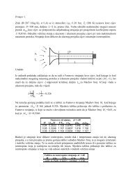
The table contains data regarding the engine power,<br />
speed and specific fuel oil consumption of the engines<br />
of the <strong>MC</strong> Programme.<br />
<strong>Engine</strong> power is specified in both BHP and kW, in<br />
rounded figures, for each cylinder number and layout<br />
points L1, L2, L3 and L4:<br />
L1 designates nominal maximum continuous rating<br />
(nominal <strong>MC</strong>R), at 100% engine power and 100%<br />
engine speed.<br />
L2, L3 and L4 designate layout points at the other<br />
three corners of the layout area, chosen for easy reference.<br />
Power<br />
L3<br />
L4<br />
Speed<br />
Fig. 1.01: Layout diagram for engine power and speed<br />
Overload corresponds to 110% of the power at<br />
<strong>MC</strong>R, and may be permitted for a limited period of<br />
one hour every 12 hours.<br />
The engine power figures given in the tables remain<br />
valid up to tropical conditions at sea level, ie.:<br />
Blower inlet temperature . . . . . . . . . . . . . . . . 45 °C<br />
Blower inlet pressure. . . . . . . . . . . . . . . 1000 mbar<br />
Seawater temperature . . . . . . . . . . . . . . . . . . 32 °C<br />
L1<br />
L2<br />
Specific fuel oil consumption (SFOC)<br />
Specific fuel oil consumption values refer to brake<br />
power, and the following reference conditions:<br />
ISO 3046/1-1986:<br />
Blower inlet temperature . . . . . . . . . . . . . . . . 25 °C<br />
Blower inlet pressure. . . . . . . . . . . . . . . 1000 mbar<br />
Charge air coolant temperature. . . . . . . . . . . 25 °C<br />
Fuel oil lower calorific value . . . . . . . . 42,700 kJ/kg<br />
(10,200 kcal/kg)<br />
Although the engine will develop the power specified<br />
up to tropical ambient conditions, the specific<br />
fuel oil consumption varies with ambient conditions<br />
and fuel oil lower calorific value. For calculation of<br />
these changes, see section 2.<br />
SFOC guarantee<br />
The figures given in this project guide represent the<br />
values obtained when the engine and turbocharger<br />
are matched with a view to obtaining the lowest<br />
possible SFOC values and fulfilling the IMO NO x<br />
emission limitations.<br />
The Specific Fuel Oil Consumption (SFOC) is guaranteed<br />
for one engine load (power-speed combination),<br />
this being the one in which the engine is optimised.<br />
The guarantee is given with a margin of 5%.<br />
As SFOC and NO x are interrelated parameters, an<br />
engine offered without fulfilling the IMO NO x limitations<br />
is subject to a tolerance of only 3% of the<br />
SFOC.<br />
Lubricating oil data<br />
The cylinder oil consumption figures stated in the<br />
tables are valid under normal conditions.<br />
During running-in periods and under special conditions,<br />
feed rates of up to 1.5 times the stated values<br />
should be used.<br />
430100 400 198 22 27<br />
1.01
MAN B&W Diesel A/S <strong>Engine</strong> <strong>Selection</strong> <strong>Guide</strong><br />
The engine types of the <strong>MC</strong> programme are<br />
identified by the following letters and figures<br />
6<br />
S 70 <strong>MC</strong> - C<br />
Fig. 1.02: <strong>Engine</strong> type designation<br />
Design<br />
Concept<br />
<strong>Engine</strong> programme<br />
Diameter of piston in cm<br />
Stroke/bore ratio<br />
Number of cylinders<br />
C Compact engine<br />
S Stationary plant<br />
C Camshaft controlled<br />
E Electronic controlled (Intelligent <strong>Engine</strong>)<br />
S Super long <strong>stroke</strong> approximately 4.0<br />
L Long <strong>stroke</strong> approximately 3.2<br />
K Short <strong>stroke</strong> approximately 2.8<br />
178 34 39-1.0<br />
430100 400 198 22 27<br />
1.02
MAN B&W Diesel A/S <strong>Engine</strong> <strong>Selection</strong> <strong>Guide</strong><br />
<strong>Engine</strong><br />
type<br />
Layout<br />
point<br />
<strong>Engine</strong><br />
speed<br />
Mean<br />
effective<br />
430100 400 198 22 27<br />
1.03<br />
Power KW<br />
BHP<br />
Number of cylinders<br />
r/min<br />
pressure<br />
bar 4 5 6 7 8 9 10 11 12<br />
K98<strong>MC</strong> L1 94 18.2<br />
34320<br />
46680<br />
40040<br />
54460<br />
45760<br />
62240<br />
51480<br />
70020<br />
57200<br />
77800<br />
62920<br />
85580<br />
68640<br />
93360<br />
Bore<br />
980 mm<br />
L2 94 14.6<br />
27480<br />
37320<br />
32060<br />
43540<br />
36640<br />
49760<br />
41220<br />
55980<br />
45800<br />
62200<br />
50380<br />
68420<br />
54960<br />
74640<br />
Stroke<br />
2660 mm L3 84 18.2<br />
30660<br />
41700<br />
35770<br />
48650<br />
40880<br />
55600<br />
45990<br />
62550<br />
51110<br />
69500<br />
56210<br />
76450<br />
61320<br />
83400<br />
L4 84 14.6<br />
24540<br />
33360<br />
28630<br />
38920<br />
32720<br />
44480<br />
36810<br />
50040<br />
40900<br />
55600<br />
44990<br />
61160<br />
49080<br />
66720<br />
K98<strong>MC</strong>-C L1 104 18.2<br />
34260<br />
46560<br />
39970<br />
54320<br />
45680<br />
62080<br />
51390<br />
69840<br />
57100<br />
77600<br />
62810<br />
85360<br />
68520<br />
93120<br />
Bore<br />
980 mm<br />
L2 104 14.6<br />
27420<br />
37260<br />
31990<br />
43470<br />
36560<br />
49680<br />
41130<br />
55890<br />
45700<br />
62100<br />
50270<br />
68310<br />
54840<br />
74520<br />
Stroke<br />
2400 mm L3 94 18.2<br />
30960<br />
42120<br />
36120<br />
49140<br />
41280<br />
56160<br />
46440<br />
63180<br />
51600<br />
70200<br />
56760<br />
77220<br />
61920<br />
84240<br />
L4 94 14.6<br />
24780<br />
33720<br />
28910<br />
39270<br />
33040<br />
44880<br />
37170<br />
50490<br />
41300<br />
56100<br />
45430<br />
61710<br />
49560<br />
67320<br />
S90<strong>MC</strong>-C L1 76 19.0<br />
29340<br />
39900<br />
34230<br />
46550<br />
39120<br />
53200<br />
44010<br />
59850<br />
Bore<br />
900 mm<br />
L2 76 15.2<br />
23520<br />
31980<br />
27440<br />
37300<br />
31360<br />
42640<br />
35280<br />
47970<br />
Stroke<br />
3188 mm L3 61 19.0<br />
23580<br />
32060<br />
27510<br />
37400<br />
31440<br />
42750<br />
35370<br />
48090<br />
L4 61 15.2<br />
18840<br />
25610<br />
21980<br />
29880<br />
25120<br />
34150<br />
28260<br />
38420<br />
L90<strong>MC</strong>-C L1 83 19.0<br />
29340<br />
39480<br />
34230<br />
46480<br />
39120<br />
53120<br />
44010<br />
59760<br />
48900<br />
66400<br />
53790<br />
73040<br />
58680<br />
79680<br />
Bore<br />
900 mm<br />
L2 83 12.2<br />
18780<br />
25500<br />
21910<br />
29750<br />
25040<br />
34000<br />
28170<br />
38250<br />
31300<br />
42500<br />
34430<br />
46750<br />
37560<br />
51000<br />
Stroke<br />
2916 mm L3 62 19.0<br />
21900<br />
29760<br />
25550<br />
34720<br />
29200<br />
39680<br />
32850<br />
44640<br />
36500<br />
49600<br />
40150<br />
54560<br />
43800<br />
59520<br />
L4 62 12.2<br />
14040<br />
19080<br />
16380<br />
22260<br />
18720<br />
25440<br />
21060<br />
28620<br />
23400<br />
31800<br />
25740<br />
34980<br />
28080<br />
38160<br />
K90<strong>MC</strong> L1 94 18.0<br />
18280<br />
24880<br />
22850<br />
31100<br />
27420<br />
37320<br />
31990<br />
43540<br />
36560<br />
49760<br />
41130<br />
55980<br />
45700<br />
62200<br />
50270<br />
68420<br />
54840<br />
74640<br />
Bore<br />
900 mm<br />
L2 94 11.5<br />
11700<br />
15920<br />
14650<br />
19900<br />
17580<br />
23880<br />
20510<br />
27860<br />
23440<br />
31840<br />
26370<br />
35820<br />
29300<br />
39800<br />
32230<br />
43780<br />
35160<br />
47760<br />
Stroke<br />
2550 mm L3 71 18.0<br />
13720<br />
18640<br />
17150<br />
23300<br />
20580<br />
27960<br />
24010<br />
32620<br />
27440<br />
37280<br />
30870<br />
41940<br />
34300<br />
46600<br />
37730<br />
51260<br />
41160<br />
55920<br />
L4 71 11.5<br />
8800<br />
11960<br />
11000<br />
14950<br />
13200<br />
17940<br />
15400<br />
20930<br />
17600<br />
23920<br />
19800<br />
26910<br />
22000<br />
29900<br />
24200<br />
32890<br />
26400<br />
35880<br />
Fig. 1.03a: Power and speed<br />
178 46 78-9.0
MAN B&W Diesel A/S <strong>Engine</strong> <strong>Selection</strong> <strong>Guide</strong><br />
<strong>Engine</strong><br />
type<br />
Layout<br />
point<br />
<strong>Engine</strong><br />
speed<br />
Mean<br />
effective<br />
Power kW<br />
BHP<br />
Number of cylinders<br />
r/min<br />
pressure<br />
bar 4 5 6 7 8 9 10 11 12<br />
K90<strong>MC</strong>-C L1 104 18.0<br />
27360<br />
37260<br />
31920<br />
43470<br />
36480<br />
49680<br />
41040<br />
55890<br />
45600<br />
62100<br />
50160<br />
68310<br />
54720<br />
74520<br />
Bore<br />
900 mm<br />
L2 104 14.4<br />
21900<br />
29820<br />
25550<br />
34790<br />
29200<br />
39760<br />
32850<br />
44730<br />
36500<br />
49700<br />
40150<br />
54670<br />
43800<br />
59640<br />
Stroke<br />
2300 mm L3 89 18.0<br />
23280<br />
31620<br />
27160<br />
36890<br />
31040<br />
42160<br />
34920<br />
47430<br />
38800<br />
52700<br />
42680<br />
57970<br />
46560<br />
63240<br />
L4 89 14.4<br />
18600<br />
25320<br />
21700<br />
29540<br />
24800<br />
33760<br />
27900<br />
37980<br />
31000<br />
42200<br />
34100<br />
46420<br />
37200<br />
50640<br />
S80<strong>MC</strong>-C L1 76 19.0<br />
23280<br />
31680<br />
27160<br />
36960<br />
31040<br />
42240<br />
Bore<br />
800 mm<br />
L2 76 12.2<br />
14880<br />
20280<br />
17360<br />
23660<br />
19840<br />
27040<br />
Stroke<br />
3200 mm L3 57 19.0<br />
17460<br />
23760<br />
20370<br />
27720<br />
23280<br />
31680<br />
L4 57 12.2<br />
11160<br />
15180<br />
13020<br />
17710<br />
14880<br />
20240<br />
S80<strong>MC</strong> L1 79 19.0<br />
15360<br />
20880<br />
19200<br />
26100<br />
23040<br />
31320<br />
26880<br />
36540<br />
30720<br />
41760<br />
34560<br />
46980<br />
Bore<br />
800 mm<br />
L2 79 12.2<br />
9840<br />
13360<br />
12300<br />
16700<br />
14760<br />
20040<br />
17220<br />
23380<br />
19680<br />
26720<br />
22140<br />
30060<br />
Stroke<br />
3056 mm L3 59 19.0<br />
11480<br />
15600<br />
14350<br />
19500<br />
17220<br />
23400<br />
20090<br />
27300<br />
22960<br />
31200<br />
25830<br />
35100<br />
L4 59 12.2<br />
7360<br />
10040<br />
9200<br />
12550<br />
11040<br />
15060<br />
12880<br />
17570<br />
14720<br />
20080<br />
16560<br />
22590<br />
L80<strong>MC</strong> L1 93 18.0<br />
14560<br />
19760<br />
18200<br />
24700<br />
21840<br />
29640<br />
25480<br />
34580<br />
29120<br />
39520<br />
32760<br />
44460<br />
36400<br />
49400<br />
40040<br />
54340<br />
43680<br />
59280<br />
Bore<br />
800 mm<br />
L2 93 11.5<br />
9320<br />
12640<br />
11650<br />
15800<br />
13980<br />
18960<br />
16310<br />
22120<br />
18640<br />
25280<br />
20970<br />
28440<br />
23300<br />
31600<br />
25630<br />
34760<br />
27960<br />
37920<br />
Stroke<br />
2592 mm L3 70 18.0<br />
10960<br />
14880<br />
13700<br />
18600<br />
16440<br />
22320<br />
19180<br />
26040<br />
21920<br />
29760<br />
24660<br />
33480<br />
27400<br />
37200<br />
30140<br />
40920<br />
32880<br />
44640<br />
L4 70 11.5<br />
7000<br />
9520<br />
8750<br />
11900<br />
10500<br />
14280<br />
12250<br />
16660<br />
14000<br />
19040<br />
15750<br />
21420<br />
17500<br />
23800<br />
19250<br />
26180<br />
21000<br />
28560<br />
K80<strong>MC</strong>-C L1 104 18.0<br />
21660<br />
29400<br />
25270<br />
34300<br />
28880<br />
39200<br />
32490<br />
44100<br />
36100<br />
49000<br />
39710<br />
53900<br />
43320<br />
58800<br />
Bore<br />
800 mm<br />
L2 104 14.4<br />
17340<br />
23520<br />
20230<br />
27440<br />
23120<br />
31360<br />
26010<br />
35280<br />
28900<br />
39200<br />
31790<br />
43120<br />
34680<br />
47040<br />
Stroke<br />
2300 mm L3 89 18.0<br />
18540<br />
25200<br />
21630<br />
29400<br />
24720<br />
33600<br />
27810<br />
37800<br />
30900<br />
42000<br />
33990<br />
46200<br />
37080<br />
50400<br />
L4 89 14.4<br />
14820<br />
20160<br />
17290<br />
23520<br />
19760<br />
26880<br />
22230<br />
30240<br />
24700<br />
33600<br />
27170<br />
36960<br />
29640<br />
40320<br />
Fig. 1.03b: Power and speed<br />
430100 400 198 22 27<br />
1.04<br />
178 46 78-9.0
MAN B&W Diesel A/S <strong>Engine</strong> <strong>Selection</strong> <strong>Guide</strong><br />
<strong>Engine</strong><br />
type<br />
Layout<br />
point<br />
<strong>Engine</strong><br />
speed<br />
Mean<br />
effective<br />
430100 400 198 22 27<br />
1.05<br />
Power kW<br />
BHP<br />
Number of cylinders<br />
r/min<br />
pressure<br />
bar 4 5 6 7 8 9 10 11 12<br />
S70<strong>MC</strong>-C L1 91 19.0<br />
12420<br />
16880<br />
15525<br />
21100<br />
18630<br />
25320<br />
21735<br />
29540<br />
24840<br />
33760<br />
Bore<br />
700 mm<br />
L2 91 12.2<br />
7940<br />
10800<br />
9925<br />
13500<br />
11910<br />
16200<br />
13895<br />
18900<br />
15880<br />
21600<br />
Stroke<br />
2800 mm L3 68 19.0<br />
9320<br />
12660<br />
11650<br />
15825<br />
13980<br />
18990<br />
16310<br />
22155<br />
18640<br />
25320<br />
L4 68 12.2<br />
5960<br />
8100<br />
7450<br />
10125<br />
8940<br />
12150<br />
10430<br />
14175<br />
11920<br />
16200<br />
S70<strong>MC</strong> L1 91 18.0<br />
11240<br />
15280<br />
14050<br />
19100<br />
16860<br />
22920<br />
19670<br />
26740<br />
22480<br />
30560<br />
Bore<br />
700 mm<br />
L2 91 11.5<br />
7200<br />
9760<br />
9000<br />
12200<br />
10800<br />
14640<br />
12600<br />
17080<br />
14400<br />
19520<br />
Stroke<br />
2674 mm L3 68 18.0<br />
8440<br />
11440<br />
10550<br />
14300<br />
12660<br />
17160<br />
14770<br />
20020<br />
16880<br />
22880<br />
L4 68 11.5<br />
5400<br />
7320<br />
6750<br />
9150<br />
8100<br />
10980<br />
9450<br />
12810<br />
10800<br />
14640<br />
L70<strong>MC</strong> L1 108 18.0<br />
11320<br />
15380<br />
14150<br />
19225<br />
16980<br />
23070<br />
19810<br />
26915<br />
22640<br />
30760<br />
Bore<br />
700 mm<br />
L2 108 11.5<br />
7240<br />
9840<br />
9050<br />
12300<br />
10860<br />
14760<br />
12670<br />
17220<br />
14480<br />
19680<br />
Stroke<br />
2268 mm L3 81 18.0<br />
8480<br />
11540<br />
10600<br />
14425<br />
12720<br />
17310<br />
14840<br />
20195<br />
16960<br />
23080<br />
L4 81 11.5<br />
5420<br />
7380<br />
6775<br />
9225<br />
8130<br />
10070<br />
9485<br />
12915<br />
10840<br />
14760<br />
S60<strong>MC</strong>-C L1 105 19.0<br />
9020<br />
12280<br />
11275<br />
15350<br />
13530<br />
18420<br />
15785<br />
21490<br />
18040<br />
24560<br />
Bore<br />
600 mm<br />
L2 105 12.2<br />
5780<br />
7860<br />
7225<br />
9825<br />
8670<br />
11790<br />
10115<br />
13755<br />
11560<br />
15720<br />
Stroke<br />
2400 mm L3 79 19.0<br />
6760<br />
9200<br />
8450<br />
11500<br />
10140<br />
13800<br />
11830<br />
16100<br />
13520<br />
18400<br />
L4 79 12.2<br />
4340<br />
5880<br />
5425<br />
7350<br />
6510<br />
8820<br />
7595<br />
10290<br />
8680<br />
11760<br />
S60<strong>MC</strong> L1 105 18.0<br />
8160<br />
11120<br />
10200<br />
13900<br />
12240<br />
16680<br />
14280<br />
19460<br />
16320<br />
22240<br />
Bore<br />
600 mm<br />
L2 105 11.5<br />
5240<br />
7120<br />
6550<br />
8900<br />
7860<br />
10680<br />
9170<br />
12460<br />
10480<br />
14240<br />
Stroke<br />
2292 mm L3 79 18.0<br />
6120<br />
8320<br />
7650<br />
10400<br />
9180<br />
12480<br />
10710<br />
14560<br />
12240<br />
16640<br />
L4 79 11.5<br />
3920<br />
5320<br />
4900<br />
6650<br />
5880<br />
7980<br />
6860<br />
9310<br />
7840<br />
10640<br />
Fig. 1.03c: Power and speed<br />
178 46 78-9.0
MAN B&W Diesel A/S <strong>Engine</strong> <strong>Selection</strong> <strong>Guide</strong><br />
<strong>Engine</strong><br />
type<br />
Layout<br />
point<br />
<strong>Engine</strong><br />
speed<br />
Mean<br />
effective<br />
430100 400 198 22 27<br />
1.06<br />
Power kW<br />
BHP<br />
Number of cylinders<br />
r/min<br />
pressure<br />
bar 4 5 6 7 8 9 10 11 12<br />
L60<strong>MC</strong> L1 123 17.0<br />
7680<br />
10400<br />
9600<br />
13000<br />
11520<br />
15600<br />
13440<br />
18200<br />
15360<br />
20800<br />
Bore<br />
600 mm<br />
L2 123 10.9<br />
4920<br />
6680<br />
6150<br />
8350<br />
7380<br />
10020<br />
8610<br />
11690<br />
9840<br />
13360<br />
Stroke<br />
1944 mm L3 92 17.0<br />
5760<br />
7800<br />
7200<br />
9750<br />
8640<br />
11700<br />
10080<br />
13650<br />
11520<br />
15600<br />
L4 92 10.9<br />
3680<br />
5000<br />
4600<br />
6250<br />
5520<br />
7500<br />
6440<br />
8750<br />
7360<br />
10000<br />
S50<strong>MC</strong>-C L1 127 19.0<br />
6320<br />
8580<br />
7900<br />
10725<br />
9480<br />
12870<br />
11060<br />
15015<br />
12640<br />
17160<br />
Bore<br />
500 mm<br />
L2 127 12.2<br />
4040<br />
5500<br />
5050<br />
6875<br />
6060<br />
8250<br />
7070<br />
9625<br />
8080<br />
11000<br />
Stroke<br />
2000 mm L3 95 19.0<br />
4740<br />
6440<br />
5925<br />
8050<br />
7110<br />
9660<br />
8295<br />
11270<br />
9480<br />
12880<br />
L4 95 12.2<br />
3040<br />
4120<br />
3800<br />
5150<br />
4560<br />
6180<br />
5320<br />
7210<br />
6080<br />
8240<br />
S50<strong>MC</strong> L1 127 18.0<br />
5720<br />
7760<br />
7150<br />
9700<br />
8580<br />
11640<br />
10010<br />
13580<br />
11440<br />
15520<br />
Bore<br />
500 mm<br />
L2 127 11.5<br />
3640<br />
4960<br />
4550<br />
6200<br />
5460<br />
7440<br />
6370<br />
8680<br />
7280<br />
9920<br />
Stroke<br />
1910 mm L3 95 18.0<br />
4280<br />
5840<br />
5350<br />
7300<br />
6420<br />
8760<br />
7490<br />
10220<br />
8560<br />
11680<br />
L4 95 11.5<br />
2760<br />
3720<br />
3450<br />
4650<br />
4140<br />
5580<br />
4830<br />
6510<br />
5520<br />
7440<br />
L50<strong>MC</strong> L1 148 17.0<br />
5320<br />
7240<br />
6650<br />
9050<br />
7980<br />
10860<br />
9310<br />
12670<br />
10640<br />
14480<br />
Bore<br />
500 mm<br />
L2 148 10.9<br />
3400<br />
4640<br />
4250<br />
5800<br />
5100<br />
6960<br />
5950<br />
8120<br />
6800<br />
9280<br />
Stroke<br />
1620 mm L3 111 17.0<br />
4000<br />
5440<br />
5000<br />
6800<br />
6000<br />
8160<br />
7000<br />
9520<br />
8000<br />
10880<br />
L4 111 10.9<br />
2560<br />
3480<br />
3200<br />
4350<br />
3840<br />
5220<br />
4480<br />
6090<br />
5120<br />
6960<br />
S46<strong>MC</strong>-C L1 129 19.0<br />
5240<br />
7140<br />
6550<br />
8925<br />
7860<br />
10710<br />
9170<br />
12495<br />
10480<br />
14280<br />
Bore<br />
460 mm<br />
L2 129 15.2<br />
4200<br />
5700<br />
5250<br />
7125<br />
6300<br />
8550<br />
7350<br />
9975<br />
8400<br />
11400<br />
Stroke<br />
1932 mm L3 108 19.0<br />
4400<br />
5980<br />
5500<br />
7475<br />
6600<br />
8970<br />
7700<br />
10465<br />
8800<br />
11960<br />
L4 108 15.2<br />
3520<br />
4780<br />
4400<br />
5975<br />
5280<br />
7170<br />
6160<br />
8365<br />
7040<br />
9560<br />
Fig. 1.03d: Power and speed<br />
178 46 78-9.0
MAN B&W Diesel A/S <strong>Engine</strong> <strong>Selection</strong> <strong>Guide</strong><br />
<strong>Engine</strong><br />
type<br />
Layout<br />
point<br />
<strong>Engine</strong><br />
speed<br />
Mean<br />
effective<br />
430100 400 198 22 27<br />
1.07<br />
Power kW<br />
BHP<br />
Number of cylinders<br />
r/min<br />
pressure<br />
bar 4 5 6 7 8 9 10 11 12<br />
S42<strong>MC</strong> L1 136 19.5<br />
4320<br />
5880<br />
5400<br />
7350<br />
6480<br />
8820<br />
7560<br />
10290<br />
8640<br />
11760<br />
9720<br />
13230<br />
10800<br />
14700<br />
11880<br />
16170<br />
12960<br />
17640<br />
Bore<br />
420 mm<br />
L2 136 15.6<br />
3460<br />
4700<br />
4325<br />
5875<br />
5190<br />
7050<br />
6055<br />
8225<br />
6920<br />
9400<br />
7785<br />
10575<br />
8650<br />
11750<br />
9515<br />
12925<br />
10380<br />
14100<br />
Stroke<br />
1764 mm L3 115 19.5<br />
3660<br />
4960<br />
4575<br />
6200<br />
5490<br />
7440<br />
6405<br />
8680<br />
7320<br />
9920<br />
8235<br />
11160<br />
9150<br />
12400<br />
10065<br />
13640<br />
10980<br />
14880<br />
L4 115 15.6<br />
2920<br />
3980<br />
3650<br />
4975<br />
4380<br />
5970<br />
5110<br />
6965<br />
5840<br />
7960<br />
6570<br />
8955<br />
7300<br />
9950<br />
8030<br />
10945<br />
8760<br />
11940<br />
L42<strong>MC</strong> L1 176 18.0<br />
3980<br />
5420<br />
4975<br />
6775<br />
5970<br />
8130<br />
6965<br />
9485<br />
7960<br />
10840<br />
8955<br />
12195<br />
9950<br />
13550<br />
10945<br />
14905<br />
11940<br />
16260<br />
Bore<br />
420 mm<br />
L2 176 11.5<br />
2540<br />
3460<br />
3175<br />
4345<br />
3810<br />
5190<br />
4445<br />
6055<br />
5080<br />
6920<br />
5715<br />
7785<br />
6350<br />
8650<br />
6985<br />
9515<br />
7620<br />
10380<br />
Stroke<br />
1360 mm L3 132 18.0<br />
2980<br />
4060<br />
3725<br />
5075<br />
4470<br />
6090<br />
5215<br />
7105<br />
5960<br />
8120<br />
6705<br />
9135<br />
7450<br />
10150<br />
8195<br />
11165<br />
8940<br />
12180<br />
L4 132 11.5<br />
1920<br />
2600<br />
2400<br />
3250<br />
2880<br />
3900<br />
3360<br />
4550<br />
3840<br />
5200<br />
4320<br />
5850<br />
4800<br />
6500<br />
5280<br />
7150<br />
5760<br />
7800<br />
S35<strong>MC</strong> L1 173 19.1<br />
2960<br />
4040<br />
3700<br />
5050<br />
4440<br />
6060<br />
5180<br />
7070<br />
5920<br />
8080<br />
6660<br />
9090<br />
7400<br />
10100<br />
8140<br />
11110<br />
8880<br />
12120<br />
Bore<br />
350 mm<br />
L2 173 15.3<br />
2380<br />
3220<br />
2975<br />
4025<br />
3570<br />
4830<br />
4165<br />
5635<br />
4760<br />
6440<br />
5355<br />
7245<br />
5950<br />
8050<br />
6545<br />
8855<br />
7140<br />
9660<br />
Stroke<br />
1400 mm L3 147 19.1<br />
2520<br />
3420<br />
3150<br />
4275<br />
3780<br />
5130<br />
4410<br />
5985<br />
5040<br />
6840<br />
5670<br />
7695<br />
6300<br />
8550<br />
6930<br />
9405<br />
7560<br />
10260<br />
L4 147 15.3<br />
2020<br />
2740<br />
2525<br />
3425<br />
3030<br />
4110<br />
3535<br />
4795<br />
4040<br />
5480<br />
4545<br />
6165<br />
5050<br />
6850<br />
5555<br />
7535<br />
6060<br />
8220<br />
L35<strong>MC</strong> L1 210 18.4<br />
2600<br />
3520<br />
3250<br />
4400<br />
3900<br />
5280<br />
4550<br />
6160<br />
5200<br />
7040<br />
5850<br />
7920<br />
6500<br />
8800<br />
7150<br />
9680<br />
7800<br />
10560<br />
Bore<br />
350 mm<br />
L2 210 14.7<br />
2080<br />
2820<br />
2600<br />
3525<br />
3120<br />
4230<br />
3640<br />
4935<br />
4160<br />
5640<br />
4680<br />
6345<br />
5200<br />
7050<br />
5720<br />
7755<br />
6240<br />
8460<br />
Stroke<br />
1050 mm L3 178 18.4<br />
2200<br />
3000<br />
2750<br />
3750<br />
3000<br />
4500<br />
3850<br />
5250<br />
4400<br />
6000<br />
4950<br />
6750<br />
5500<br />
7500<br />
6050<br />
8250<br />
6600<br />
9000<br />
L4 178 14.7<br />
1760<br />
2400<br />
2200<br />
3000<br />
2640<br />
3600<br />
3080<br />
4200<br />
3520<br />
4800<br />
3960<br />
5400<br />
4400<br />
6600<br />
4840<br />
6600<br />
5280<br />
7200<br />
S26<strong>MC</strong> L1 250 18.5<br />
1600<br />
2180<br />
2000<br />
2725<br />
2400<br />
3270<br />
2800<br />
3815<br />
3200<br />
4360<br />
3600<br />
4905<br />
4000<br />
5450<br />
4400<br />
5995<br />
4800<br />
6540<br />
Bore<br />
260 mm<br />
L2 250 14.8<br />
1280<br />
1740<br />
1600<br />
2175<br />
1920<br />
2610<br />
2240<br />
3045<br />
2560<br />
3480<br />
2880<br />
3915<br />
3200<br />
4350<br />
3520<br />
4785<br />
3840<br />
5220<br />
Stroke<br />
980 mm<br />
L3 212 18.5<br />
1360<br />
1860<br />
1700<br />
2325<br />
2040<br />
2790<br />
2380<br />
3255<br />
2720<br />
3720<br />
3060<br />
4185<br />
3400<br />
4650<br />
3740<br />
5115<br />
4080<br />
5580<br />
L4 212 14.8<br />
1100<br />
1480<br />
1375<br />
1850<br />
1650<br />
2220<br />
1925<br />
2590<br />
2200<br />
2960<br />
2475<br />
3330<br />
2750<br />
3700<br />
3025<br />
4070<br />
3300<br />
4440<br />
Fig. 1.03e: Power and speed<br />
178 46 78-9.0
MAN B&W Diesel A/S <strong>Engine</strong> <strong>Selection</strong> <strong>Guide</strong><br />
Specific fuel oil consumption<br />
g/kWh<br />
g/BHPh<br />
Lubricating oil consumption<br />
With high efficiency turbochargers System oil Cylinder oil<br />
At load layout point 100% 80%<br />
K98<strong>MC</strong><br />
and<br />
K98<strong>MC</strong>-C<br />
S90<strong>MC</strong>-C<br />
L90<strong>MC</strong>-C<br />
K90<strong>MC</strong><br />
L1<br />
L2<br />
L3<br />
L4<br />
L1<br />
L2<br />
L3<br />
L4<br />
L1<br />
L2<br />
L3<br />
L4<br />
L1<br />
L2<br />
L3<br />
L4<br />
171<br />
126<br />
162<br />
119<br />
171<br />
126<br />
162<br />
119<br />
167<br />
123<br />
160<br />
118<br />
167<br />
123<br />
160<br />
118<br />
167<br />
123<br />
155<br />
114<br />
167<br />
123<br />
155<br />
114<br />
171<br />
126<br />
159<br />
117<br />
171<br />
126<br />
159<br />
117<br />
Fig. 1.04a: Fuel and lubricating oil consumption<br />
Approx.<br />
kg/cyl. 24h<br />
g/kWh<br />
g/BHPh<br />
430 100 100 198 22 28<br />
1.08<br />
165<br />
121<br />
158<br />
116<br />
165<br />
121<br />
158<br />
116<br />
165<br />
121<br />
157<br />
116<br />
165<br />
121<br />
157<br />
116<br />
165<br />
121<br />
154<br />
113<br />
165<br />
121<br />
154<br />
113<br />
169<br />
124<br />
158<br />
116<br />
169<br />
124<br />
158<br />
116<br />
7.5-11<br />
7-10<br />
7-10<br />
7-10<br />
0.8-1.2<br />
0.6-0.9<br />
0.95-1.5<br />
0.7-1.1<br />
0.8-1.2<br />
0.6-0.9<br />
0.8-1.2<br />
0.6-0.9<br />
178 46 79-2.0
MAN B&W Diesel A/S <strong>Engine</strong> <strong>Selection</strong> <strong>Guide</strong><br />
Specific fuel oil consumption<br />
430 100 100 198 22 28<br />
1.09<br />
g/kWh<br />
g/BHPh<br />
Lubricating oil consumption<br />
With high efficiency turbochargers System oil Cylinder oil<br />
At load layout point 100% 80%<br />
K90<strong>MC</strong>-C<br />
S80<strong>MC</strong>-C<br />
S80<strong>MC</strong><br />
L80<strong>MC</strong><br />
L1<br />
L2<br />
L3<br />
L4<br />
L1<br />
L2<br />
L3<br />
L4<br />
L1<br />
L2<br />
L3<br />
L4<br />
L1<br />
L2<br />
L3<br />
L4<br />
171<br />
126<br />
165<br />
121<br />
171<br />
126<br />
165<br />
121<br />
167<br />
123<br />
155<br />
114<br />
167<br />
123<br />
155<br />
114<br />
167<br />
123<br />
155<br />
114<br />
167<br />
123<br />
155<br />
114<br />
174<br />
128<br />
162<br />
119<br />
174<br />
128<br />
162<br />
119<br />
Fig. 1.04b: Fuel and lubricating oil consumption<br />
169<br />
124<br />
162<br />
119<br />
169<br />
124<br />
162<br />
119<br />
165<br />
121<br />
154<br />
113<br />
165<br />
121<br />
154<br />
113<br />
165<br />
121<br />
154<br />
113<br />
165<br />
121<br />
154<br />
113<br />
171<br />
126<br />
160<br />
118<br />
171<br />
126<br />
160<br />
118<br />
Approx.<br />
kg/cyl. 24h<br />
7-10<br />
6-9<br />
6-9<br />
6-9<br />
g/kWh<br />
g/BHPh<br />
0.8-1.2<br />
0.6-0.9<br />
0.95-1.5<br />
0.7-1.1<br />
0.95-1.5<br />
0.7-1.1<br />
0.8-1.2<br />
0.6-0.9<br />
178 46 79-2.0
MAN B&W Diesel A/S <strong>Engine</strong> <strong>Selection</strong> <strong>Guide</strong><br />
Specific fuel oil consumption<br />
With conventional<br />
turbochargers<br />
g/kWh<br />
g/BHPh<br />
With high efficiency<br />
turbochargers<br />
At load layout point 100% 80% 100% 80%<br />
K80<strong>MC</strong>-C<br />
S70<strong>MC</strong>-C<br />
S70<strong>MC</strong><br />
L70<strong>MC</strong><br />
L1<br />
L2<br />
L3<br />
L4<br />
L1<br />
L2<br />
L3<br />
L4<br />
L1<br />
L2<br />
L3<br />
L4<br />
L1<br />
L2<br />
L3<br />
L4<br />
171<br />
126<br />
159<br />
117<br />
171<br />
126<br />
159<br />
117<br />
171<br />
126<br />
159<br />
117<br />
171<br />
126<br />
159<br />
117<br />
Fig. 1.04c: Fuel and lubricating oil consumption<br />
169<br />
124<br />
158<br />
116<br />
169<br />
124<br />
158<br />
116<br />
169<br />
124<br />
158<br />
116<br />
169<br />
124<br />
158<br />
116<br />
Lubricating oil consumption<br />
System oil Cylinder oil<br />
Approx.<br />
kg/cyl. 24h<br />
g/kWh<br />
g/BHPh<br />
430 100 100 198 22 28<br />
1.10<br />
171<br />
126<br />
165<br />
121<br />
171<br />
126<br />
165<br />
121<br />
169<br />
124<br />
156<br />
115<br />
169<br />
124<br />
156<br />
115<br />
169<br />
124<br />
156<br />
115<br />
169<br />
124<br />
156<br />
115<br />
174<br />
128<br />
162<br />
119<br />
174<br />
128<br />
162<br />
119<br />
169<br />
124<br />
162<br />
119<br />
169<br />
124<br />
162<br />
119<br />
166<br />
122<br />
155<br />
114<br />
166<br />
122<br />
155<br />
114<br />
166<br />
122<br />
155<br />
114<br />
166<br />
122<br />
155<br />
114<br />
171<br />
126<br />
160<br />
118<br />
171<br />
126<br />
160<br />
118<br />
6-9<br />
5.5-7.5<br />
5.5-7.5<br />
5.5-7.5<br />
0.8-1.2<br />
0.6-0.9<br />
0.95-1.5<br />
0.7-1.1<br />
0.95-1.5<br />
0.7-1.1<br />
0.8-1.2<br />
0.6-0.9<br />
178 46 79-2.0
MAN B&W Diesel A/S <strong>Engine</strong> <strong>Selection</strong> <strong>Guide</strong><br />
Specific fuel oil consumption<br />
With conventional<br />
turbochargers<br />
g/kWh<br />
g/BHPh<br />
With high efficiency<br />
turbochargers<br />
At load layout point 100% 80% 100% 80%<br />
S60<strong>MC</strong>-C<br />
S60<strong>MC</strong><br />
L60<strong>MC</strong><br />
S50<strong>MC</strong>-C<br />
L1<br />
L2<br />
L3<br />
L4<br />
L1<br />
L2<br />
L3<br />
L4<br />
L1<br />
L2<br />
L3<br />
L4<br />
L1<br />
L2<br />
L3<br />
L4<br />
173<br />
127<br />
160<br />
118<br />
173<br />
127<br />
160<br />
118<br />
173<br />
127<br />
160<br />
118<br />
173<br />
127<br />
160<br />
118<br />
174<br />
128<br />
162<br />
119<br />
174<br />
128<br />
162<br />
119<br />
174<br />
128<br />
162<br />
119<br />
174<br />
128<br />
162<br />
119<br />
Fig. 1.05d: Fuel and lubricating oil consumption<br />
170<br />
125<br />
159<br />
117<br />
170<br />
125<br />
159<br />
117<br />
170<br />
125<br />
159<br />
117<br />
170<br />
125<br />
159<br />
117<br />
171<br />
126<br />
160<br />
118<br />
171<br />
126<br />
160<br />
118<br />
171<br />
126<br />
160<br />
118<br />
171<br />
126<br />
160<br />
118<br />
Lubricating oil consumption<br />
System oil Cylinder oil<br />
Approx.<br />
kg/cyl. 24h<br />
g/kWh<br />
g/BHPh<br />
430 100 100 198 22 28<br />
1.11<br />
170<br />
125<br />
158<br />
116<br />
170<br />
125<br />
158<br />
116<br />
170<br />
125<br />
158<br />
116<br />
170<br />
125<br />
158<br />
116<br />
171<br />
126<br />
159<br />
117<br />
171<br />
126<br />
159<br />
117<br />
171<br />
126<br />
159<br />
117<br />
171<br />
126<br />
159<br />
117<br />
167<br />
123<br />
156<br />
115<br />
167<br />
123<br />
156<br />
115<br />
167<br />
123<br />
156<br />
115<br />
167<br />
123<br />
156<br />
115<br />
169<br />
124<br />
158<br />
116<br />
169<br />
124<br />
158<br />
116<br />
169<br />
124<br />
158<br />
116<br />
169<br />
124<br />
158<br />
116<br />
5-6.5<br />
5-6.5<br />
5-6.5<br />
4-5<br />
0.95-1.5<br />
0.7-1.1<br />
0.95-1.5<br />
0.7-1.1<br />
0.8-1.2<br />
0.6-0.9<br />
0.95-1.5<br />
0.7-1.1<br />
178 46 79-2.0
MAN B&W Diesel A/S <strong>Engine</strong> <strong>Selection</strong> <strong>Guide</strong><br />
Specific fuel oil consumption<br />
With conventional<br />
turbochargers<br />
430 100 100 198 22 28<br />
1.12<br />
g/kWh<br />
g/BHPh<br />
With high efficiency<br />
turbochargers<br />
At load layout point 100% 80% 100% 80%<br />
S50<strong>MC</strong><br />
L50<strong>MC</strong><br />
S46<strong>MC</strong>-C<br />
S42<strong>MC</strong><br />
L1<br />
L2<br />
L3<br />
L4<br />
L1<br />
L2<br />
L3<br />
L4<br />
L1<br />
L2<br />
L3<br />
L4<br />
L1<br />
L2<br />
L3<br />
L4<br />
174<br />
128<br />
162<br />
119<br />
174<br />
128<br />
162<br />
119<br />
175<br />
129<br />
163<br />
120<br />
175<br />
129<br />
163<br />
120<br />
174<br />
128<br />
169<br />
124<br />
174<br />
128<br />
169<br />
124<br />
177<br />
130<br />
171<br />
126<br />
177<br />
130<br />
171<br />
126<br />
Fig. 1.05e: Fuel and lubricating oil consumption<br />
171<br />
126<br />
160<br />
118<br />
171<br />
126<br />
160<br />
118<br />
173<br />
127<br />
162<br />
119<br />
173<br />
127<br />
162<br />
119<br />
173<br />
127<br />
167<br />
123<br />
173<br />
127<br />
167<br />
123<br />
175<br />
129<br />
170<br />
125<br />
175<br />
129<br />
170<br />
125<br />
171<br />
126<br />
159<br />
117<br />
171<br />
126<br />
159<br />
117<br />
173<br />
127<br />
160<br />
118<br />
173<br />
127<br />
160<br />
118<br />
169<br />
124<br />
158<br />
116<br />
169<br />
124<br />
158<br />
116<br />
170<br />
125<br />
159<br />
117<br />
170<br />
125<br />
159<br />
117<br />
Lubricating oil consumption<br />
System oil Cylinder oil<br />
Approx.<br />
kg/cyl. 24h<br />
4-5<br />
4-5<br />
3.5-4.5<br />
3-4<br />
g/kWh<br />
g/BHPh<br />
0.95-1.5<br />
0.7-1.1<br />
0.8-1.2<br />
0.6-0.9<br />
0.95-1.5<br />
0.7-1.1<br />
0.95-1.5<br />
0.7-1.1<br />
178 46 79-2.0
MAN B&W Diesel A/S <strong>Engine</strong> <strong>Selection</strong> <strong>Guide</strong><br />
Specific fuel oil consumption<br />
g/kWh<br />
g/BHPh<br />
At load layout point 100% 80%<br />
L42<strong>MC</strong><br />
S35<strong>MC</strong><br />
L35<strong>MC</strong><br />
S26<strong>MC</strong><br />
L1<br />
L2<br />
L3<br />
L4<br />
L1<br />
L2<br />
L3<br />
L4<br />
L1<br />
L2<br />
L3<br />
L4<br />
L1<br />
L2<br />
L3<br />
L4<br />
Lubricating oil consumption<br />
With conventional turbochargers System oil Cylinder oil<br />
177<br />
130<br />
165<br />
121<br />
177<br />
130<br />
165<br />
121<br />
178<br />
131<br />
173<br />
127<br />
178<br />
131<br />
173<br />
127<br />
177<br />
130<br />
171<br />
126<br />
177<br />
130<br />
171<br />
126<br />
179<br />
132<br />
174<br />
128<br />
179<br />
132<br />
174<br />
128<br />
Fig. 1.05f: Fuel and lubricating oil consumption<br />
Approx.<br />
kg/cyl. 24h<br />
g/kWh<br />
g/BHPh<br />
430 100 100 198 22 28<br />
1.13<br />
174<br />
129<br />
163<br />
120<br />
174<br />
129<br />
163<br />
120<br />
177<br />
130<br />
171<br />
126<br />
177<br />
130<br />
171<br />
126<br />
175<br />
129<br />
170<br />
125<br />
175<br />
129<br />
170<br />
125<br />
178<br />
131<br />
173<br />
127<br />
178<br />
131<br />
173<br />
127<br />
3-4<br />
2-3<br />
2-3<br />
1.5-3<br />
0.8-1.2<br />
0.6-0.9<br />
0.95-1.5<br />
0.7-1.1<br />
0.8-1.2<br />
0.6-0.9<br />
0.95-1.5<br />
0.7-1.1<br />
178 46 79-2.0
MAN B&W Diesel A/S <strong>Engine</strong> <strong>Selection</strong> <strong>Guide</strong><br />
Fig. 1.05: K98<strong>MC</strong> engine cross section<br />
430 100 018 198 22 29<br />
1.14<br />
178 32 80-6.1
MAN B&W Diesel A/S <strong>Engine</strong> <strong>Selection</strong> <strong>Guide</strong><br />
Fig. 1.06: S80<strong>MC</strong> engine cross section<br />
430 100 018 198 22 29<br />
1.15<br />
178 36 24-7.0
MAN B&W Diesel A/S <strong>Engine</strong> <strong>Selection</strong> <strong>Guide</strong><br />
Fig. 1.07: S70<strong>MC</strong>-C engine cross section<br />
178 44 14-4.1<br />
430 100 018 198 22 29<br />
1.16
MAN B&W Diesel A/S <strong>Engine</strong> <strong>Selection</strong> <strong>Guide</strong><br />
Fig. 1.08: S60<strong>MC</strong> engine cross section<br />
430 100 018 198 22 29<br />
1.17<br />
178 32 19-8.0
MAN B&W Diesel A/S <strong>Engine</strong> <strong>Selection</strong> <strong>Guide</strong><br />
Fig. 1.09: S50<strong>MC</strong>-C engine cross section<br />
178 16 07-0.0<br />
430 100 018 198 22 29<br />
1.18
MAN B&W Diesel A/S <strong>Engine</strong> <strong>Selection</strong> <strong>Guide</strong><br />
Fig. 1.10: L42<strong>MC</strong> engine cross section<br />
430 100 018 198 22 29<br />
1.19<br />
178 43 10-1.0
MAN B&W Diesel A/S <strong>Engine</strong> <strong>Selection</strong> <strong>Guide</strong><br />
Fig. 1.11: S26<strong>MC</strong> engine cross section<br />
430 100 018 198 22 29<br />
1.20<br />
178 42 12-5.0
MAN B&W Diesel A/S <strong>Engine</strong> <strong>Selection</strong> <strong>Guide</strong><br />
2 <strong>Engine</strong> Layout and Load Diagrams<br />
Propulsion and <strong>Engine</strong> Running Points<br />
Propeller curve<br />
The relation between power and propeller speed for<br />
a fixed pitch propeller is as mentioned above described<br />
by means of the propeller law, i.e. the third<br />
power curve:<br />
Pb =cxn 3 , in which:<br />
Pb = engine power for propulsion<br />
n = propeller speed<br />
c = constant<br />
The power functions Pb =cxn i will be linear functions<br />
when using logarithmic scales.<br />
Therefore, in the Layout Diagrams and Load Diagrams<br />
for diesel engines, logarithmic scales are<br />
used, making simple diagrams with straight lines.<br />
Propeller design point<br />
Normally, estimations of the necessary propeller<br />
power and speed are based on theoretical calculations<br />
for loaded ship, and often experimental tank<br />
tests, both assuming optimum operating conditions,<br />
i.e. a clean hull and good weather. The combination<br />
of speed and power obtained may be called<br />
the ship’s propeller design point (PD), placed on the<br />
light running propeller curve 6. See Fig. 2.01. On the<br />
other hand, some shipyards, and/or propeller manufacturers<br />
sometimes use a propeller design point<br />
(PD’) that incorporates all or part of the so-called<br />
sea margin described below.<br />
Fouled hull<br />
When the ship has sailed for some time, the hull and<br />
propeller become fouled and the hull’s resistance<br />
will increase. Consequently, the ship speed will be<br />
reduced unless the engine delivers more power to<br />
the propeller, i.e. the propeller will be further loaded<br />
and will be heavy running (HR).<br />
As modern vessels with a relatively high service<br />
speed are prepared with very smooth propeller and<br />
hull surfaces, the fouling after sea trial, therefore,<br />
will involve a relatively higher resistance and thereby<br />
a heavier running propeller.<br />
Sea margin at heavy weather<br />
If, at the same time the weather is bad, with head<br />
winds, the ship’s resistance may increase compared<br />
to operating at calm weather conditions.<br />
When determining the necessary engine power, it is<br />
therefore normal practice to add an extra power<br />
margin, the so-called sea margin, see Fig. 2.02<br />
which is traditionally about 15% of the propeller design<br />
(PD) power.<br />
<strong>Engine</strong> layout (heavy propeller)<br />
When determining the necessary engine speed<br />
considering the influence of a heavy running propeller<br />
for operating at large extra ship resistance, it is<br />
recommended - compared to the clean hull and<br />
calm weather propeller curve6-tochoose a heavier<br />
propeller curve 2 for engine layout, and the propeller<br />
402 000 004 198 22 30<br />
2.01<br />
178 05 41-5.3<br />
Line 2 Propulsion curve, fouled hull and heavy weather<br />
(heavy running), recommended for engine layout<br />
Line 6 Propulsion curve, clean hull and calm weather<br />
(light running), for propeller layout<br />
MP Specified <strong>MC</strong>R for propulsion<br />
SP Continuous service rating for propulsion<br />
PD Propeller design point<br />
HR Heavy running<br />
LR Light running<br />
Fig. 2.01: Ship propulsion running points and engine layout
MAN B&W Diesel A/S <strong>Engine</strong> <strong>Selection</strong> <strong>Guide</strong><br />
curve for clean hull and calm weather in curve 6 will<br />
be said to represent a “light running” (LR) propeller,<br />
see area 6 on Figs. 2.07a and 2.07b.<br />
Compared to the heavy engine layout curve 2 we<br />
recommend to use a light running of 3.0-7.0% for<br />
design of the propeller, with 5% as a good average.<br />
<strong>Engine</strong> margin<br />
178 05 67-7.1<br />
Fig. 2.02: Sea margin based on weather conditions in the<br />
North Atlantic Ocean. Percentage of time at sea where<br />
the service speed can be maintained, related to the extra<br />
power (sea margin) in % of the sea trial power.<br />
Besides the sea margin, a so-called “engine margin”<br />
of some 10% is frequently added. The corresponding<br />
point is called the “specified <strong>MC</strong>R for propulsion”<br />
(MP), and refers to the fact that the power<br />
for point SP is 10% lower than for point MP, see Fig.<br />
2.01. Point MP is identical to the engine’s specified<br />
<strong>MC</strong>R point (M) unless a main engine driven shaft<br />
generator is installed. In such a case, the extra<br />
power demand of the shaft generator must also be<br />
considered.<br />
Note:<br />
Light/heavy running, fouling and sea margin are<br />
overlapping terms. Light/heavy running of the propeller<br />
refers to hull and propeller deterioration and<br />
heavy weather and, – sea margin i.e. extra power to<br />
the propeller, refers to the influence of the wind and<br />
the sea. However, the degree of light running must<br />
be decided upon experience from the actual trade<br />
and hull design.<br />
402 000 004 198 22 30<br />
2.02
MAN B&W Diesel A/S <strong>Engine</strong> <strong>Selection</strong> <strong>Guide</strong><br />
Influence of propeller diameter and pitch on<br />
the optimum propeller speed<br />
In general, the larger the propeller diameter, the<br />
lower is the optimum propeller speed and the kW<br />
required for a certain design draught and ship<br />
speed, see curve D in Fig. 2.03.<br />
The maximum possible propeller diameter depends<br />
on the given design draught of the ship, and the<br />
clearance needed between the propeller and the<br />
aft-body hull and the keel.<br />
The example shown in Fig. 2.03 is an 80,000 dwt<br />
crude oil tanker with a design draught of 12.2 m and<br />
a design speed of 14.5 knots.<br />
When the optimum propeller diameter D is increased<br />
from 6.6 m to 7.2. m, the power demand is<br />
reduced from about 9,290 kW to 8,820 kW, and the<br />
optimum propeller speed is reduced from 120 r/min<br />
to 100 r/min, corresponding to the constant ship<br />
speed coefficient = 28 (see definition of in next<br />
section).<br />
Fig. 2.03: Influence of diameter and pitch on propeller design<br />
Once an optimum propeller diameter of maximum<br />
7.2 m has been chosen, the pitch in this point is<br />
given for the design speed of 14.5 knots, i.e. P/D =<br />
0.70.<br />
However, if the optimum propeller speed of 100<br />
r/min does not suit the preferred / selected main engine<br />
speed, a change of pitch will only cause a relatively<br />
small extra power demand, keeping the same<br />
maximum propeller diameter:<br />
• going from 100 to 110 r/min (P/D = 0.62) requires<br />
8,900 kW i.e. an extra power demand of 80 kW.<br />
• going from 100 to 91 r/min (P/D = 0.81) requires<br />
8,900 kW i.e. an extra power demand of 80 kW.<br />
In both cases the extra power demand is only of<br />
0.9%, and the corresponding 'equal speed curves'<br />
are =+0.1 and =-0.1, respectively, so there is a<br />
certain interval of propeller speeds in which the<br />
'power penalty' is very limited.<br />
402 000 004 198 22 30<br />
2.03<br />
178 47 03-2.0
MAN B&W Diesel A/S <strong>Engine</strong> <strong>Selection</strong> <strong>Guide</strong><br />
Constant ship speed lines<br />
The constant ship speed lines , are shown at the<br />
very top of Fig. 2.04. These lines indicate the power<br />
required at various propeller speeds to keep the<br />
same ship speed provided that the optimum propeller<br />
diameter with an optimum pitch diameter ratio is<br />
used at any given speed, taking into consideration<br />
the total propulsion efficiency.<br />
Normally, the following relation between necessary<br />
power and propeller speed can be assumed:<br />
P2 =P1 (n2/n1) <br />
where:<br />
P = Propulsion power<br />
n = Propeller speed, and<br />
= the constant ship speed coefficient.<br />
For any combination of power and speed, each<br />
point on lines parallel to the ship speed lines gives<br />
the same ship speed.<br />
When such a constant ship speed line is drawn into<br />
the layout diagram through a specified propulsion<br />
Fig. 2.04: Layout diagram and constant ship speed lines<br />
<strong>MC</strong>R point "MP1", selected in the layout area and<br />
parallel to one of the -lines, another specified propulsion<br />
<strong>MC</strong>R point "MP2" upon this line can be chosen<br />
to give the ship the same speed for the new<br />
combination of engine power and speed.<br />
Fig. 2.04 shows an example of the required power<br />
speed point MP1, through which a constant ship<br />
speed curve = 0.25 is drawn, obtaining point MP2<br />
with a lower engine power and a lower engine speed<br />
but achieving the same ship speed.<br />
Provided the optimum pitch/diameter ratio is used<br />
for a given propeller diameter the following data applies<br />
when changing the propeller diameter:<br />
for general cargo, bulk carriers and tankers<br />
= 0.25 -0.30<br />
and for reefers and container vessels<br />
= 0.15 -0.25<br />
When changing the propeller speed by changing the<br />
pitch diameter ratio, the constant will be different,<br />
see above.<br />
402 000 004 198 22 30<br />
2.04<br />
178 05 66-7.0
MAN B&W Diesel A/S <strong>Engine</strong> <strong>Selection</strong> <strong>Guide</strong><br />
<strong>Engine</strong> Layout Diagram<br />
The layout procedure has to be carefully considered<br />
because the final layout choice will have a considerable<br />
influence on the operating condition of the main<br />
engine throughout the whole lifetime of the ship. The<br />
factors that should be conisdered are operational flexibility,<br />
fuel consumption, obtainable power, possible<br />
shaft generator application and propulsion efficiency.<br />
An engine’s layout diagram is limited by two constant<br />
mean effective pressure (mep) lines L1-L3 and L2-L4,<br />
and by two constant engine speed lines L1-L2 and<br />
L3-L4, see Fig. 2.04. The L1 point refers to the engine’s<br />
nominal maximum continuous rating.<br />
Please note that the areas of the layout diagrams are<br />
different for the engines types, see Fig. 2.05.<br />
Within the layout area there is full freedom to select the<br />
engine’s specified <strong>MC</strong>R point M which suits the demand<br />
of propeller power and speed for the ship.<br />
On the X-axis the engine speed and on the Y-axis the<br />
engine power are shown in percentage scales. The<br />
scales are logarithmic which means that, in this diagram,<br />
power function curves like propeller curves (3rd<br />
power), constant mean effective pressure curves (1st<br />
power) and constant ship speed curves (0.15 to 0.30<br />
power) are straight lines.<br />
Fig. 2.06 shows, by means of superimposed diagrams<br />
for all engine types, the entire layout area for the<br />
<strong>MC</strong>-programme in a power/speed diagram. As can be<br />
seen, there is a considerable overlap of power/speed<br />
combinations so that for nearly all applications, there<br />
is a wide section of different engines to choose from all<br />
of which meet the individual ship's requirements.<br />
Specified maximum continuous rating, S<strong>MC</strong>R = “M”<br />
Based on the propulsion and engine running points,<br />
as previously found, the layout diagram of a relevant<br />
main engine may be drawn-in. The specified <strong>MC</strong>R<br />
point (M) must be inside the limitation lines of the layout<br />
diagram; if it is not, the propeller speed will have to<br />
be changed or another main engine type must be chosen.<br />
Yet, in special cases point M may be located to<br />
the right of the line L1-L2, see “Optimising Point”.<br />
402 000 004 198 22 30<br />
2.05<br />
Power<br />
Power<br />
Power<br />
Power<br />
L 3<br />
L 4<br />
L 3<br />
L 4<br />
L 3<br />
L 4<br />
L 3<br />
L 4<br />
L 1<br />
L 2<br />
Speed<br />
L 1<br />
L 2<br />
Speed<br />
L 1<br />
L 2<br />
Speed<br />
L 1<br />
L 2<br />
Speed<br />
Fig. 2.05: Layout diagram sizes<br />
Layout diagram of<br />
100 - 64% power and<br />
100 - 75% speed range<br />
valid for the types:<br />
L90<strong>MC</strong>-C S60<strong>MC</strong>-C<br />
K90<strong>MC</strong> S60<strong>MC</strong><br />
S80<strong>MC</strong>-C L60<strong>MC</strong><br />
S80<strong>MC</strong> S50<strong>MC</strong>-C<br />
L80<strong>MC</strong> S50<strong>MC</strong><br />
S70<strong>MC</strong>-C L50<strong>MC</strong><br />
S70<strong>MC</strong> L42<strong>MC</strong><br />
L70<strong>MC</strong><br />
Layout diagram of<br />
100 - 80% power and<br />
100 - 80% speed range<br />
valid for the types:<br />
S90<strong>MC</strong>-C<br />
Layout diagram of<br />
100 - 80% power and<br />
100 - 85% speed range<br />
valid for the types:<br />
K90<strong>MC</strong>-C<br />
K80<strong>MC</strong>-C<br />
S46<strong>MC</strong>-C<br />
S42<strong>MC</strong><br />
S35<strong>MC</strong><br />
L35<strong>MC</strong><br />
S26<strong>MC</strong><br />
Layout diagram of<br />
100 - 80% power and<br />
100 - 90% speed range<br />
valid for the types:<br />
K98<strong>MC</strong><br />
K98<strong>MC</strong>-C<br />
178 13 85-1.4
MAN B&W Diesel A/S <strong>Engine</strong> <strong>Selection</strong> <strong>Guide</strong><br />
Fig. 2.06: Layout diagrams of the two-<strong>stroke</strong> engine <strong>MC</strong>-programme as per January 2000<br />
402 000 004 198 22 30<br />
2.06<br />
178 13 80-2.8
MAN B&W Diesel A/S <strong>Engine</strong> <strong>Selection</strong> <strong>Guide</strong><br />
Continuous service rating (S)<br />
The Continuous service rating is the power at which<br />
the engine is normally assumed to operate, and<br />
point S is identical to the service propulsion point<br />
(SP) unless a main engine driven shaft generator is<br />
installed.<br />
Optimising point (O)<br />
The optimising point O is the rating at which the<br />
turbocharger is matched, and at which the engine timing<br />
and compression ratio are adjusted.<br />
On engines with Variable Injection Timing (VIT) fuel<br />
pumps, the optimising point (O) can be different than<br />
the specified <strong>MC</strong>R (M), whereas on engines without<br />
VIT fuel pumps “O” has to coincide with “M”.<br />
The large engine types have VIT fuel pumps as standard,<br />
but on some types these pumps are an option.<br />
Small-bore engines are not fitted with VIT fuel pumps.<br />
Type With VIT Without VIT<br />
K98<strong>MC</strong> Basic<br />
K98<strong>MC</strong>-C Basic<br />
S90<strong>MC</strong>-C Basic<br />
L90<strong>MC</strong>-C Basic<br />
K90<strong>MC</strong> Basic<br />
K90<strong>MC</strong>-C Basic<br />
S80<strong>MC</strong>-C Basic<br />
S80<strong>MC</strong> Basic<br />
L80<strong>MC</strong> Basic<br />
S70<strong>MC</strong>-C Optional Basic<br />
S70<strong>MC</strong> Basic<br />
L70<strong>MC</strong> Basic<br />
S60<strong>MC</strong>-C Optional Basic<br />
S60<strong>MC</strong> Basic<br />
L60<strong>MC</strong> Basic<br />
S50<strong>MC</strong>-C Optional Basic<br />
S50<strong>MC</strong> Basic<br />
S46<strong>MC</strong>-C Basic<br />
S42<strong>MC</strong> Basic<br />
L42<strong>MC</strong> Basic<br />
S35<strong>MC</strong> Basic<br />
L35<strong>MC</strong> Basic<br />
S26<strong>MC</strong> Basic<br />
<strong>Engine</strong>s with VIT<br />
The optimising point O is placed on line 1 of the load<br />
diagram, and the optimised power can be from 85 to<br />
100% of point M's power, when turbocharger(s) and<br />
engine timing are taken into consideration. When<br />
optimising between 93.5% and 100% of point M's<br />
power, 10% overload running will still be possible<br />
(110% of M).<br />
The optimising point O is to be placed inside the layout<br />
diagram. In fact, the specified <strong>MC</strong>R point M can,<br />
in special cases, be placed outside the layout diagram,<br />
but only by exceeding line L1-L2, and of<br />
course, only provided that the optimising point O is<br />
located inside the layout diagram and provided that<br />
the specified <strong>MC</strong>R power is not higher than the L1<br />
power.<br />
<strong>Engine</strong> without VIT<br />
Optimising point (O) = specified <strong>MC</strong>R (M)<br />
On engine types not fitted with VIT fuel pumps,<br />
the specified <strong>MC</strong>R – point M has to coincide with<br />
point O.<br />
402 000 004 198 22 30<br />
2.07
MAN B&W Diesel A/S <strong>Engine</strong> <strong>Selection</strong> <strong>Guide</strong><br />
Load Diagram<br />
Definitions<br />
The load diagram, Figs. 2.07, defines the power and<br />
speed limits for continuous as well as overload operation<br />
of an installed engine having an optimising<br />
point O and a specified <strong>MC</strong>R point M that confirms<br />
the ship’s specification.<br />
Point A is a 100% speed and power reference point<br />
of the load diagram, and is defined as the point on<br />
the propeller curve (line 1), through the optimising<br />
point O, having the specified <strong>MC</strong>R power. Normally,<br />
point M is equal to point A, but in special cases, for<br />
example if a shaft generator is installed, point M may<br />
be placed to the right of point A on line 7.<br />
The service points of the installed engine incorporate<br />
the engine power required for ship propulsion<br />
and shaft generator, if installed.<br />
Limits for continuous operation<br />
The continuous service range is limited by four lines:<br />
Line 3 and line 9:<br />
Line 3 represents the maximum acceptable speed<br />
for continuous operation, i.e. 105% of A.<br />
If, in special cases, A is located to the right of line<br />
L1-L2, the maximum limit, however, is 105% of L1.<br />
During trial conditions the maximum speed may be<br />
extended to 107% of A, see line 9.<br />
The above limits may in general be extended to<br />
105%, and during trial conditions to 107%, of the<br />
nominal L1 speed of the engine, provided the torsional<br />
vibration conditions permit.<br />
The overspeed set-point is 109% of the speed in A,<br />
however, it may be moved to 109% of the nominal<br />
speed in L1, provided that torsional vibration conditions<br />
permit.<br />
Running above 100% of the nominal L1 speed at a<br />
load lower than about 65% specified <strong>MC</strong>R is, however,<br />
to be avoided for extended periods. Only<br />
plants with controllable pitch propellers can reach<br />
this light running area.<br />
Line 4:<br />
Represents the limit at which an ample air supply<br />
is available for combustion and imposes a limitation<br />
on the maximum combination of torque and<br />
speed.<br />
Line 5:<br />
Represents the maximum mean effective pressure<br />
level (mep), which can be accepted for continuous<br />
operation.<br />
Line 7:<br />
Represents the maximum power for continuous<br />
operation.7<br />
Limits for overload operation<br />
The overload service range is limited as follows:<br />
Line 8:<br />
Represents the overload operation limitations.<br />
The area between lines 4, 5, 7 and the heavy dashed<br />
line 8 is available for overload running for limited periods<br />
only (1 hour per 12 hours).<br />
402 000 004 198 22 30<br />
2.08<br />
A 100% reference point<br />
M Specified <strong>MC</strong>R point<br />
O Optimising point<br />
Line 1 Propeller curve through optimising point (i = 3)<br />
(engine layout curve)<br />
Line 2 Propeller curve, fouled hull and heavy weather<br />
– heavy running (i = 3)<br />
Line 3 Speed limit<br />
Line 4 Torque/speed limit (i = 2)<br />
Line 5 Mean effective pressure limit (i = 1)<br />
Line 6 Propeller curve, clean hull and calm weather –<br />
light running (i = 3), for propeller layout<br />
Line 7 Power limit for continuous running (i = 0)<br />
Line 8 Overload limit<br />
Line 9 Speed limit at sea trial<br />
Point M to be located on line 7 (normally in point A)<br />
Regarding “i” in the power functions Pb =cxn i , see<br />
page 2.01
MAN B&W Diesel A/S <strong>Engine</strong> <strong>Selection</strong> <strong>Guide</strong><br />
Fig. 2.07a: <strong>Engine</strong> load diagram for engine with VIT<br />
Fig. 2.07b: <strong>Engine</strong> load diagram for engine without VIT<br />
402 000 004 198 22 30<br />
2.09<br />
178 05 42-7.3<br />
178 39 18-4.1
MAN B&W Diesel A/S <strong>Engine</strong> <strong>Selection</strong> <strong>Guide</strong><br />
Recommendation<br />
Continuous operation without limitations is allowed<br />
only within the area limited by lines 4, 5, 7 and 3 of<br />
the load diagram, except for CP propeller plants<br />
mentioned in the previous section.<br />
The area between lines 4 and 1 is available for operation<br />
in shallow waters, heavy weather and during<br />
acceleration, i.e. for non-steady operation without<br />
any strict time limitation.<br />
After some time in operation, the ship’s hull and propeller<br />
will be fouled, resulting in heavier running of<br />
the propeller, i.e. the propeller curve will move to the<br />
left from line 6 towards line 2, and extra power is required<br />
for propulsion in order to keep the ship’s<br />
speed.<br />
In calm weather conditions, the extent of heavy running<br />
of the propeller will indicate the need for cleaning<br />
the hull and possibly polishing the propeller.<br />
Once the specified <strong>MC</strong>R (and the optimising point)<br />
has been chosen, the capacities of the auxiliary<br />
equipment will be adapted to the specified <strong>MC</strong>R,<br />
and the turbocharger etc. will be matched to the optimised<br />
power, however considering the specified<br />
<strong>MC</strong>R.<br />
If the specified <strong>MC</strong>R (and/or the optimising point) is<br />
to be increased later on, this may involve a change<br />
of the pump and cooler capacities, retiming of the<br />
engine, change of the fuel valve nozzles, adjusting<br />
of the cylinder liner cooling, as well as rematching of<br />
the turbocharger or even a change to a larger size of<br />
turbocharger. In some cases it can also require<br />
larger dimensions of the piping systems.<br />
It is therefore of utmost importance to consider, already<br />
at the project stage, if the specification should<br />
be prepared for a later power increase.<br />
Examples of the use of the Load Diagram<br />
In the following see Figs. 2.08 - 2.13, are some examples<br />
illustrating the flexibility of the layout and<br />
load diagrams and the significant influence of the<br />
choice of the optimising point O.<br />
The upper diagrams of the examples 1, 2, 3 and 4<br />
show engines with VIT fuel pumps for which the optimising<br />
point O is normally different from the specified<br />
<strong>MC</strong>R point M as this can improve the SFOC at<br />
part load running. The lower diagrams also show<br />
engine wihtout VIT fuel pumps, i.e. point A=O.<br />
Example 1 shows how to place the load diagram for<br />
an engine without shaft generator coupled to a fixed<br />
pitch propeller.<br />
In example 2 are diagrams for the same configuration,<br />
here with the optimising point to the left of the<br />
heavy running propeller curve (2) obtaining an extra<br />
engine margin for heavy running.<br />
As for example 1 example 3 shows the same layout<br />
for an engine with fixed pitch propeller, but with a<br />
shaft generator.<br />
Example 4 shows a special case with a shaft generator.<br />
In this case the shaft generator is cut off, and<br />
the GenSets used when the engine runs at specified<br />
<strong>MC</strong>R. This makes it possible to choose a smaller engine<br />
with a lower power output.<br />
Example 5 shows diagrams for an engine coupled to<br />
a controllable pitch propeller, with or without a shaft<br />
generator, (constant speed or combinator curve operation).<br />
Example 6 shows where to place the optimising<br />
point for an engine coupled to a controllable pitch<br />
propeller, and operating at constant speed.<br />
For a project, the layout diagram shown in Fig.<br />
2.14 may be used for construction of the actual<br />
load diagram.<br />
402 000 004 198 22 30<br />
2.10
MAN B&W Diesel A/S <strong>Engine</strong> <strong>Selection</strong> <strong>Guide</strong><br />
Example 1:<br />
Normal running conditions. <strong>Engine</strong> coupled to fixed pitch propeller (FPP) and without shaft generator<br />
With VIT<br />
M Specified <strong>MC</strong>R of engine Point A of load diagram is found:<br />
S Continuous service rating of engine Line 1 Propeller curve through optimising point (O) is<br />
O Optimising point of engine<br />
equal to line 2<br />
A Reference point of load diagram Line 7 Constant power line through specified <strong>MC</strong>R (M)<br />
MP Specified <strong>MC</strong>R for propulsion Point A Intersection between line 1 and 7<br />
SP Continuous service rating of propulsion<br />
For engines with VIT, the optimising point O and its propeller<br />
curve 1 will normally be selected on the engine<br />
service curve 2, see the upper diagram of Fig. 2.08a.<br />
For engines without VIT, the optimising point O will<br />
have the same power as point M and its propeller<br />
curve 1 for engine layout will normally be selected<br />
Without VIT<br />
Fig. 2.08a: Example 1, Layout diagram for normal running Fig. 2.08b: Example 1, Load diagram for normal running<br />
conditions, engine with FPP, without shaft generator conditions, engine with FPP, without shaft generator<br />
on the engine service curve 2 (for fouled hull and<br />
heavy weather), as shown in the lower diagram of<br />
Fig. 2.08a.<br />
Point A is then found at the intersection between propeller<br />
curve 1 (2) and the constant power curve through<br />
M, line 7. In this case point A is equal to point M.<br />
402 000 004 198 22 30<br />
2.11<br />
178 05 44-0.6<br />
178 39 20-6.1
MAN B&W Diesel A/S <strong>Engine</strong> <strong>Selection</strong> <strong>Guide</strong><br />
Example 2:<br />
Special running conditions. <strong>Engine</strong> coupled to fixed pitch propeller (FPP) and without shaft generator<br />
M Specified <strong>MC</strong>R of engine Point A of load diagram is found:<br />
S Continuous service rating of engine Line 1 Propeller curve through optimising point (O)<br />
O Optimising point of engine<br />
is equal to line 2<br />
A Reference point of load diagram Line 7 Constant power line through specified <strong>MC</strong>R (M)<br />
MP Specified <strong>MC</strong>R for propulsion Point A Intersection between line 1 and 7<br />
SP Continuous service rating of propulsion<br />
Fig. 2.09a: Example 2, Layout diagram for special running<br />
conditions, engine with FPP, without shaft generator<br />
Once point A has been found in the layout diagram,<br />
the load diagram can be drawn, as shown in Fig.<br />
2.08b and hence the actual load limitation lines of the<br />
diesel engine may be found by using the inclinations<br />
from the construction lines and the %-figures stated.<br />
With VIT<br />
Without VIT<br />
A similar example 2 is shown in Figs. 2.09. In this<br />
case, the optimising point O has been selected<br />
more to the left than in example 1, obtaining an extra<br />
engine margin for heavy running operation in heavy<br />
weather conditions. In principle, the light running<br />
margin has been increased for this case.<br />
402 000 004 198 22 30<br />
2.12<br />
178 05 46-4.6<br />
178 39 23-1.0<br />
Fig. 2.09b: Example 2, Load diagram for special running<br />
conditions, engine with FPP, without shaft generator
MAN B&W Diesel A/S <strong>Engine</strong> <strong>Selection</strong> <strong>Guide</strong><br />
Example 3:<br />
Normal running conditions. <strong>Engine</strong> coupled to fixed pitch propeller (FPP) and with shaft generator<br />
M Specified <strong>MC</strong>R of engine Point A of load diagram is found:<br />
S Continuous service rating of engine Line 1 Propeller curve through optimising point (O)<br />
O Optimising point of engine Line 7 Constant power line through specified <strong>MC</strong>R (M)<br />
A Reference point of load diagram Point A Intersection between line 1 and 7<br />
MP Specified <strong>MC</strong>R for propulsion<br />
SP Continuous service rating of propulsion<br />
SG Shaft generator power<br />
Fig. 2.10a: Example 3, Layout diagram for normal running<br />
conditions, engine with FPP, without shaft generator<br />
In example 3 a shaft generator (SG) is installed, and<br />
therefore the service power of the engine also has to<br />
incorporate the extra shaft power required for the<br />
shaft generator’s electrical power production.<br />
In Fig. 2.10a, the engine service curve shown for<br />
heavy running incorporates this extra power.<br />
With VIT<br />
Without VIT<br />
The optimising point O will be chosen on the engine<br />
service curve as shown, but can, by an approximation,<br />
be located on curve 1, through point M.<br />
Point A is then found in the same way as in example<br />
1, and the load diagram can be drawn as shown in<br />
Fig. 2.10b.<br />
402 000 004 198 22 30<br />
2.13<br />
178 05 48-8.6<br />
178 39 25-5.1<br />
Fig. 2.10b: Example 3, Load diagram for normal running<br />
conditions, engine with FPP, with shaft generator
MAN B&W Diesel A/S <strong>Engine</strong> <strong>Selection</strong> <strong>Guide</strong><br />
Example 4:<br />
Special running conditions. <strong>Engine</strong> coupled to fixed pitch propeller (FPP) and with shaft generator<br />
M Specified <strong>MC</strong>R of engine Point A of load diagram is found:<br />
S Continuous service rating of engine Line 1 Propeller curve through optimising point (O) or<br />
point S<br />
O Optimising point of engine Point A Intersection between line 1 and line L1 -L3<br />
A Reference point of load diagram Point M Located on constant power line 7 through<br />
MP Specified <strong>MC</strong>R for propulsion<br />
SP Continuous service rating of propulsion<br />
SG Shaft generator<br />
See text on next page.<br />
Fig. 2.11a: Example 4. Layout diagram for special running<br />
conditions, engine with FPP, with shaft generator<br />
With VIT<br />
Without VIT<br />
402 000 004 198 22 30<br />
2.14<br />
178 06 35-1.6<br />
point A (O =Aiftheengine is without VIT)<br />
and with MP's speed.<br />
178 39 28-0.2<br />
Fig. 2.11b: Example 4. Load diagram for special running<br />
conditions, engine with FPP, with shaft generator
MAN B&W Diesel A/S <strong>Engine</strong> <strong>Selection</strong> <strong>Guide</strong><br />
Example 4:<br />
Also in this special case, a shaft generator is installed<br />
but, compared to Example 3, this case has a<br />
specified <strong>MC</strong>R for propulsion, MP, placed at the top<br />
of the layout diagram, see Fig. 2.11a.<br />
This involves that the intended specified <strong>MC</strong>R of the<br />
engine M’ will be placed outside the top of the layout<br />
diagram.<br />
One solution could be to choose a larger diesel<br />
engine with an extra cylinder, but another and<br />
cheaper solution is to reduce the electrical power<br />
production of the shaft generator when running in<br />
the upper propulsion power range.<br />
In choosing the latter solution, the required specified<br />
<strong>MC</strong>R power can be reduced from point M’ to<br />
point M as shown in Fig. 2.11a. Therefore, when running<br />
in the upper propulsion power range, a diesel<br />
generator has to take over all or part of the electrical<br />
power production.<br />
However, such a situation will seldom occur, as<br />
ships are rather infrequently running in the upper<br />
propulsion power range.<br />
Point A, having the highest possible power, is<br />
then found at the intersection of line L1-L3 with<br />
line 1, see Fig. 2.11a, and the corresponding load<br />
diagram is drawn in Fig. 2.11b. Point M is found<br />
on line 7 at MP’s speed.<br />
402 000 004 198 22 30<br />
2.15
MAN B&W Diesel A/S <strong>Engine</strong> <strong>Selection</strong> <strong>Guide</strong><br />
Example 5:<br />
<strong>Engine</strong> coupled to controllable pitch propeller (CPP) with or without shaft generator<br />
Without VIT<br />
With VIT<br />
M Specified <strong>MC</strong>R of engine O Optimising point of engine<br />
S Continuous service rating of engine A Reference point of load diagram<br />
Fig. 2.12: Example 5: <strong>Engine</strong> with Controllable Pitch Propeller (CPP), with or without shaft generator<br />
Fig. 2.12 shows two examples: on the left diagrams<br />
for an engine without VIT fuel pumps (A=O=M),on<br />
the right, for an engine with VIT fuel pumps (A = M).<br />
Layout diagram - without shaft generator<br />
If a controllable pitch propeller (CPP) is applied, the<br />
combinator curve (of the propeller) will normally be<br />
selected for loaded ship including sea margin.<br />
The combinator curve may for a given propeller speed<br />
have a given propeller pitch, and this may be heavy running<br />
in heavy weather like for a fixed pitch propeller.<br />
Therefore it is recommended to use a light running<br />
combinator curve as shown in Fig. 2.12 to obtain an<br />
increased operation margin of the diesel engine in<br />
heavy weather to the limit indicated by curves 4 and 5.<br />
Layout diagram - with shaft generator<br />
The hatched area in Fig. 2.12 shows the recommended<br />
speed range between 100% and 96.7% of<br />
the specified <strong>MC</strong>R speed for an engine with shaft<br />
generator running at constant speed.<br />
The service point S can be located at any point<br />
within the hatched area.<br />
The procedure shown in examples 3 and 4 for engines<br />
with FPP can also be applied here for engines<br />
with CPP running with a combinator curve.<br />
The optimising point O for engines with VIT may be<br />
chosen on the propeller curve through point A=M<br />
with an optimised power from 85 to 100% of the<br />
specified <strong>MC</strong>R as mentioned before in the section<br />
dealing with optimising point O.<br />
Load diagram<br />
Therefore, when the engine’s specified <strong>MC</strong>R point<br />
(M) has been chosen including engine margin, sea<br />
margin and the power for a shaft generator, if installed,<br />
point M may be used as point A of the load<br />
diagram, which can then be drawn.<br />
The position of the combinator curve ensures the<br />
maximum load range within the permitted speed<br />
range for engine operation, and it still leaves a reasonable<br />
margin to the limit indicated by curves 4<br />
and 5.<br />
Example 6 will give a more detailed description of<br />
how to run constant speed with a CP propeller.<br />
402 000 004 198 22 30<br />
2.16<br />
178 39 31-4.1
MAN B&W Diesel A/S <strong>Engine</strong> <strong>Selection</strong> <strong>Guide</strong><br />
Example 6: <strong>Engine</strong>s with VIT fuel pumps running<br />
at constant speed with controllable pitch<br />
propeller (CPP)<br />
Fig. 2.13a Constant speed curve through M, normal<br />
and correct location of the optimising point O<br />
Irrespective of whether the engine is operating on a<br />
propeller curve or on a constant speed curve<br />
through M, the optimising point O must be located<br />
on the propeller curve through the specified <strong>MC</strong>R<br />
point M or, in special cases, to the left of point M.<br />
The reason is that the propeller curve 1 through the<br />
optimising point O is the layout curve of the engine,<br />
and the intersection between curve 1 and the maximum<br />
power line 7 through point M is equal to 100%<br />
power and 100% speed, point A of the load diagram<br />
- in this case A=M.<br />
In Fig. 2.13a the optimising point O has been placed<br />
correctly, and the step-up gear and the shaft generator,<br />
if installed, may be synchronised on the constant<br />
speed curve through M.<br />
Fig. 2.13b: Constant speed curve through M,<br />
wrong position of optimising point O<br />
If the engine has been service-optimised in point O<br />
on a constant speed curve through point M, then the<br />
specified <strong>MC</strong>R point M would be placed outside the<br />
load diagram, and this is not permissible.<br />
Fig. 2.13c: Recommended constant speed running<br />
curve, lower than speed M<br />
In this case it is assumed that a shaft generator, if installed,<br />
is synchronised at a lower constant main engine<br />
speed (for example with speed equal to O or<br />
lower) at which improved CP propeller efficiency is<br />
obtained for part load running.<br />
In this layout example where an improved CP propeller<br />
efficiency is obtained during extended periods<br />
of part load running, the step-up gear and the<br />
shaft generator have to be designed for the applied<br />
lower constant engine speed.<br />
402 000 004 198 22 30<br />
2.17<br />
Constant speed service<br />
curve through M<br />
Fig. 2.13a: Normal procedure<br />
Constant speed service<br />
curve through M<br />
Fig. 2.13b: Wrong procedure<br />
Constant speed service<br />
curve with a speed lower<br />
than M<br />
Fig. 2.13c: Recommended procedure<br />
Logarithmic scales<br />
M: Specified <strong>MC</strong>R<br />
O: Optimised point<br />
A: 100% power and speed of load<br />
diagram (normally A=M)<br />
Fig. 2.13: Running at constant speed with CPP<br />
178 19 69-9.0
MAN B&W Diesel A/S <strong>Engine</strong> <strong>Selection</strong> <strong>Guide</strong><br />
Fig. 2.14 contains a layout diagram that can be used for construction<br />
of the load diagram for an actual project, using the<br />
%-figures stated and the inclinations of the lines.<br />
Fig. 2.14: Diagram for actual project<br />
178 46 87-5.0<br />
402 000 004 198 22 30<br />
2.18
MAN B&W Diesel A/S <strong>Engine</strong> <strong>Selection</strong> <strong>Guide</strong><br />
Emission Control<br />
IMO NOx emission limits<br />
All <strong>MC</strong> engines are delivered so as to comply with<br />
the IMO speed dependent NOx limit, measured according<br />
to ISO 8178 Test Cycles E2/E3 for Heavy<br />
Duty Diesel <strong>Engine</strong>s.<br />
The Specific Fuel Oil Consumption (SFOC) and the<br />
NOx are interrelated parameters, and an engine offered<br />
with a guaranteed SFOC and also guaranteed<br />
to comply with the IMO NOx limitation will be subject<br />
to a 5% fuel consumption tolerance.<br />
30-50% NOx reduction<br />
Water emulsification of the heavy fuel oil is a well<br />
proven primary method. The type of homogenizer is<br />
either ultrasonic or mechanical, using water from<br />
the freshwater generator and the water mist<br />
catcher. The pressure of the homogenised fuel has<br />
to be increased to prevent the formation of the<br />
steam and cavitation. It may be necessary to modify<br />
some of the engine components such as the fuel<br />
pumps, camshaft, and the engine control system.<br />
Up to 95-98% NOx reduction<br />
This reduction can be achieved by means of secondary<br />
methods, such as the SCR (Selective Catalytic<br />
Reduction), which involves an after-treatment<br />
of the exhaust gas.<br />
Plants designed according to this method have<br />
been in service since 1990 on four vessels, using<br />
Haldor Topsøe catalysts and ammonia as the reducing<br />
agent, urea can also be used.<br />
The compact SCR unit can be located separately in<br />
the engine room or horizontally on top of the engine.<br />
The compact SCR reactor is mounted before the<br />
turbocharger(s) in order to have the optimum working<br />
temperature for the catalyst.<br />
More detailed information can be found in our publications:<br />
P. 331 Emissions Control, <strong>Two</strong>-<strong>stroke</strong> Low-speed<br />
<strong>Engine</strong>s<br />
P. 333 How to deal with Emission Control.<br />
402 000 004 198 22 30<br />
2.19
MAN B&W Diesel A/S <strong>Engine</strong> <strong>Selection</strong> <strong>Guide</strong><br />
Specific Fuel Oil Consumption<br />
<strong>Engine</strong> with from 98 to 50 cm bore engines are as<br />
standard fitted with high efficiency turbochargers.<br />
The smaller bore from 46 to 26 cm are fitted with the<br />
so-called "conventional" turbochargers<br />
High efficiency/conventional turbochargers<br />
Some engine types are as standard fitted with high<br />
efficiency turbochargers but can alternatively use<br />
conventional turbochargers. These are:<br />
S70<strong>MC</strong>-C, S70<strong>MC</strong>, S60<strong>MC</strong>-C, S60<strong>MC</strong>, L60<strong>MC</strong>,<br />
S50<strong>MC</strong>-C, S50<strong>MC</strong> and L50<strong>MC</strong>.<br />
The high efficiency turbocharger is applied to the<br />
engine in the basic design with the view to obtaining<br />
the lowest possible Specific Fuel Oil Consumption<br />
(SFOC) values.<br />
Fig. 2.15: Example of part load SFOC curves for the two engine versions<br />
With a conventional turbocharger the amount of air<br />
required for combustion purposes can, however, be<br />
adjusted to provide a higher exhaust gas temperature,<br />
if this is needed for the exhaust gas boiler. The<br />
matching of the engine and the turbocharging system<br />
is then modified, thus increasing the exhaust<br />
gas temperature by 20 °C.<br />
This modification will lead to a 7-8% reduction in the<br />
exhaust gas amount, and involve an SFOC penalty<br />
of up to 2 g/BHPh, see the example in Fig. 2.15.<br />
The calculation of the expected specific fuel oil consumption<br />
(SFOC) can be carried out by means of the<br />
following figures for fixed pitch propeller and for<br />
controllable pitch propeller, constant speed.<br />
Throughout the whole load area the SFOC of the engine<br />
depends on where the optimising point O is<br />
chosen.<br />
402 000 004 198 22 30<br />
2.20<br />
178 47 08-1.0
MAN B&W Diesel A/S <strong>Engine</strong> <strong>Selection</strong> <strong>Guide</strong><br />
SFOC at reference conditions<br />
The SFOC is based on the reference ambient conditions<br />
stated in ISO 3046/1-1986:<br />
1,000 mbar ambient air pressure<br />
25 °C ambient air temperature<br />
25 °C scavenge air coolant temperature<br />
and is related to a fuel oil with a lower calorific value of<br />
10,200 kcal/kg (42,700 kJ/kg).<br />
For lower calorific values and for ambient conditions<br />
that are different from the ISO reference conditions,<br />
the SFOC will be adjusted according to the conversion<br />
factors in the below table provided that the maximum<br />
combustion pressure (Pmax) is adjusted to the<br />
nominal value (left column), or if the Pmax is not<br />
re-adjusted to the nominal value (right column).<br />
Parameter Condition change<br />
With<br />
Pmax<br />
adjusted<br />
SFOC<br />
change<br />
Without<br />
Pmax<br />
adjusted<br />
SFOC<br />
change<br />
Scav. air coolant<br />
temperature per 10 °C rise + 0.60% + 0.41%<br />
Blower inlet<br />
temperature per 10 °C rise<br />
+ 0.20% + 0.71%<br />
Blower inlet<br />
pressure per 10 mbar rise - 0.02% - 0.05%<br />
Fuel oil lower<br />
calorific value<br />
rise 1%<br />
(42,700 kJ/kg)<br />
-1.00% - 1.00%<br />
With for instance 1 °C increase of the scavenge air<br />
coolant temperature, a corresponding 1 °C increase<br />
of the scavenge air temperature will occur and involves<br />
an SFOC increase of 0.06% if Pmax is adjusted.<br />
SFOC guarantee<br />
The SFOC guarantee refers to the above ISO reference<br />
conditions and lower calorific value, and is guaranteed<br />
for the power-speed combination in which the<br />
engine is optimised (O).<br />
The SFOC guarantee is given with a margin of 5% for<br />
engines fulfilling the IMO NOx emission limitations.<br />
As SFOC and NOx are interrelated paramaters, an engine<br />
offered without fulfilling the IMO NOx limitations<br />
only has a tolerance of 3% of the SFOC.<br />
Examples of graphic calculation of<br />
SFOC<br />
Diagram 1 in the following figures are valid for fixed<br />
pitch propeller and constant speed, respectively,<br />
shows the reduction in SFOC, relative to the SFOC<br />
at nominal rated <strong>MC</strong>R L1.<br />
The solid lines are valid at 100, 80 and 50% of the<br />
optimised power (O).<br />
The optimising point O is drawn into the abovementioned<br />
Diagram 1. A straight line along the<br />
constant mep curves (parallel to L1-L3) is drawn<br />
through the optimising point O. The line intersections<br />
of the solid lines and the oblique lines indicate<br />
the reduction in specific fuel oil consumption<br />
at 100%, 80% and 50% of the optimised power,<br />
related to the SFOC stated for the nominal <strong>MC</strong>R<br />
(L1) rating at the actually available engine version.<br />
The SFOC curve for an engine with conventional<br />
turbocharger is identical to that for an engine with<br />
high efficiency turbocharger, but located at 2<br />
g/BHPh higher level.<br />
In Fig. 2.24 an example of the calculated SFOC<br />
curves are shown on Diagram 2, valid for two alternative<br />
engine ratings: O1 = 100% M and<br />
O2 = 85%M for a 6S70<strong>MC</strong>-C with VIT fuel pumps.<br />
402 000 004 198 22 30<br />
2.21
MAN B&W Diesel A/S <strong>Engine</strong> <strong>Selection</strong> <strong>Guide</strong><br />
SFOC in g/BHPh at nominal <strong>MC</strong>R (L1)<br />
<strong>Engine</strong> kW/cyl. BHP/cyl. r/min g/kWh g/BHPh<br />
6-12K98<strong>MC</strong> 5720 7780 94 171 126<br />
6-12K98<strong>MC</strong>-C 5710 7760 104 171 126<br />
Data optimising point (O):<br />
Power: 100% of (O) BHP<br />
Speed: 100% of (O) r/min<br />
SFOC found: g/BHPh<br />
These figures are valid both for engines with fixed pitch propeller and for engines running at constant speed.<br />
Fig. 2.16a: SFOC for engines with fixed pitch propeller, K98<strong>MC</strong> and K98<strong>MC</strong>-C<br />
178 87 11-3.0<br />
402 000 004 198 22 30<br />
2.22<br />
178 44 22-7.1
MAN B&W Diesel A/S <strong>Engine</strong> <strong>Selection</strong> <strong>Guide</strong><br />
Fig. 2.16b: SFOC for engines with constant speed,<br />
402 000 004 198 22 30<br />
2.23<br />
178 44 22-7.0<br />
178 44 22-7.1
MAN B&W Diesel A/S <strong>Engine</strong> <strong>Selection</strong> <strong>Guide</strong><br />
402 000 004 198 22 30<br />
2.24<br />
SFOC in g/BHPh at nominal <strong>MC</strong>R (L1)<br />
<strong>Engine</strong> kW/cyl. BHP/cyl. r/min g/kWh g/BHPh<br />
6-9S90<strong>MC</strong>-C 4890 6650 76 167 123<br />
Fig. 2.17a: Example of SFOC for engines with fixed pitch propeller, S90<strong>MC</strong>-C<br />
178 37 74-4.0<br />
178 87 12-5.0
MAN B&W Diesel A/S <strong>Engine</strong> <strong>Selection</strong> <strong>Guide</strong><br />
Fig. 2.17b: Example of SFOC for engines with constant speed,<br />
178 37 75-6.0<br />
178 11 68-5.0<br />
402 000 004 198 22 30<br />
2.25
MAN B&W Diesel A/S <strong>Engine</strong> <strong>Selection</strong> <strong>Guide</strong><br />
Fig. 2.18a: Example of SFOC for engines with fixed pitch propeller,<br />
SFOC in g/BHPh at nominal <strong>MC</strong>R (L1)<br />
)<strong>Engine</strong> kW/cyl. BHP/cyl. r/min g/kWh g/BHPh<br />
6-12K90<strong>MC</strong>-C 4560 6210 104 171 126<br />
6-12K80<strong>MC</strong>-C 3610 4900 104 171 126<br />
Data optimising point (O):<br />
Power: 100% of (O) BHP<br />
Speed: 100% of (O) r/min<br />
SFOC: g/BHPh<br />
178 06 87-7.0<br />
402 000 004 198 22 30<br />
2.26<br />
178 87 13-7.0<br />
178 39 35-1.0
MAN B&W Diesel A/S <strong>Engine</strong> <strong>Selection</strong> <strong>Guide</strong><br />
Fig. 2.18b: Example of SFOC for engines with constant speed,<br />
178 06 89-0.0<br />
402 000 004 198 22 30<br />
2.27<br />
178 44 22-7.1
MAN B&W Diesel A/S <strong>Engine</strong> <strong>Selection</strong> <strong>Guide</strong><br />
Fig. 2.19a: Example of SFOC for engines with fixed pitch propeller<br />
178 15 92-3.0<br />
SFOC in g/BHPh at nominal <strong>MC</strong>R (L1)<br />
Turbochargers<br />
High efficiency Conventional<br />
<strong>Engine</strong> kW/cyl. BHP/cyl. r/min g/kWh g/BHPh g/kWh g/BHPh<br />
6-12L90<strong>MC</strong>-C 4890 6650 83 167 123<br />
4-12K90<strong>MC</strong> 4570 6220 94 171 126<br />
6-8S80<strong>MC</strong>-C 3880 5280 76 167 123<br />
4-9S80<strong>MC</strong> 3840 5220 79 167 123<br />
4-12L80<strong>MC</strong> 3640 4940 93 174 128<br />
4-8S70<strong>MC</strong>-C* 3105 4220 91 169 124 171 126<br />
4-8S70<strong>MC</strong> 2810 3820 91 169 124 171 126<br />
4-8L70<strong>MC</strong> 2830 3845 108 174 128<br />
4-8S60<strong>MC</strong>-C* 2255 3070 105 170 125 173 127<br />
4-8S60<strong>MC</strong> 2040 2780 105 170 125 173 127<br />
4-8L60<strong>MC</strong> 1920 2600 123 171 126 174 128<br />
4-8S50<strong>MC</strong>-C* 1580 2145 127 171 126 174 128<br />
4-8S50<strong>MC</strong> 1430 1940 127 171 126 174 128<br />
4-8L50<strong>MC</strong> 1330 1810 148 173 127 175 129<br />
4-12L42<strong>MC</strong>* 995 1355 176 177 130<br />
* Note: <strong>Engine</strong>s without VIT fuel pumps have to be optimised at the specified <strong>MC</strong>R power<br />
These figures are valid both for engines with fixed pitch propeller and for engines running at constant speed.<br />
Data optimising point (O):<br />
Power: 100% of (O) BHP<br />
Speed: 100% of (O) r/min<br />
SFOC found: g/BHPh<br />
178 43 63-9.0<br />
402 000 004 198 22 30<br />
2.28
MAN B&W Diesel A/S <strong>Engine</strong> <strong>Selection</strong> <strong>Guide</strong><br />
Fig. 2.19b: Example of SFOC for engines with constant speed<br />
178 15 91-1.0<br />
178 43 63-9.0<br />
402 000 004 198 22 30<br />
2.29
MAN B&W Diesel A/S <strong>Engine</strong> <strong>Selection</strong> <strong>Guide</strong><br />
Specified <strong>MC</strong>R (M) = optimised point (O)<br />
SFOC in g/BHPh at nominal <strong>MC</strong>R (L1)<br />
<strong>Engine</strong> kW/cyl. BHP/cyl. r/min g/kWh g/BHPh<br />
4-8S46<strong>MC</strong>-C 1310 1785 129 174 128<br />
4-12S42<strong>MC</strong> 1080 1470 136 177 130<br />
4-12S35<strong>MC</strong> 740 1010 173 178 131<br />
4-12L35<strong>MC</strong> 650 880 210 177 130<br />
4-12S26<strong>MC</strong> 400 545 250 179 132<br />
Data optimising point (O):<br />
Power: 100% of (O) BHP<br />
Speed: 100% of (O) r/min<br />
These figures are valid both for engines with fixed pitch propeller and for engines running at constant speed.<br />
Fig. 2.20a: Example of SFOC for engines with fixed pitch propeller<br />
178 06 88-9.0<br />
402 000 004 198 22 30<br />
2.30<br />
178 87 15-0.0
MAN B&W Diesel A/S <strong>Engine</strong> <strong>Selection</strong> <strong>Guide</strong><br />
Specified <strong>MC</strong>R (M) = optimised point (O)<br />
Fig. 2.20b: Example of SFOC for engines with constant speed<br />
178 43 63-9.0<br />
402 000 004 198 22 30<br />
2.31<br />
178 06 90-0.0
MAN B&W Diesel A/S <strong>Engine</strong> <strong>Selection</strong> <strong>Guide</strong><br />
Fig. 2.21: Example of SFOC for 6S70<strong>MC</strong>-C with fixed pitch propeller, high efficiency turbocharger and VIT fuel pumps<br />
178 15 88-8.0<br />
Data at nominal <strong>MC</strong>R (L1): 6S70<strong>MC</strong>-C Data of optimising point (O) O1 O2<br />
100% Power:<br />
100% Speed:<br />
High efficiency turbocharger:<br />
25,320<br />
91<br />
124<br />
BHP<br />
r/min<br />
g/BHPh<br />
Power: 100% of O<br />
Speed: 100% of O<br />
SFOC found:<br />
178 43 67-6.0<br />
402 000 004 198 22 30<br />
2.32<br />
21,000 BHP<br />
81.9 r/min<br />
122.1 g/BHPh<br />
Note: <strong>Engine</strong>s without VIT fuel pumps have to be optimised at the specified <strong>MC</strong>R power<br />
O1: Optimised in M<br />
O2: Optimised at 85% of power M<br />
Point 3: is 80% of O2 = 0.80 x 85% of M = 68% M<br />
Point 4: is 50% of O2 = 0.50 x 85% of M = 42.5% M<br />
17,850 BHP<br />
77.4 r/min<br />
119.7 g/BHPh<br />
178 43 66-4.0
MAN B&W Diesel A/S <strong>Engine</strong> <strong>Selection</strong> <strong>Guide</strong><br />
Fuel Consumption at an Arbitrary Load<br />
Once the engine has been optimised in point O,<br />
shown on this Fig., the specific fuel oil consumption<br />
in an arbitrary point S1, S2 or S3 can be estimated<br />
based on the SFOC in points “1" and ”2".<br />
These SFOC values can be calculated by using the<br />
graphs for fixed pitch propeller (curve I) and for the<br />
constant speed (curve II), obtaining the SFOC in<br />
points 1 and 2, respectively.<br />
Then the SFOC for point S1 can be calculated as an<br />
interpolation between the SFOC in points “1" and<br />
”2", and for point S3 as an extrapolation.<br />
Fig. 2.22: SFOC at an arbitrary load<br />
The SFOC curve through points S2, to the left of<br />
point 1, is symmetrical about point 1, i.e. at speeds<br />
lower than that of point 1, the SFOC will also increase.<br />
The above-mentioned method provides only an approximate<br />
figure. A more precise indication of the<br />
expected SFOC at any load can be calculated by<br />
using our computer program. This is a service which<br />
is available to our customers on request.<br />
178 05 32-0.1<br />
402 000 004 198 22 30<br />
2.33
MAN B&W Diesel A/S <strong>Engine</strong> <strong>Selection</strong> <strong>Guide</strong><br />
3 Turbocharger Choice<br />
Turbocharger Types<br />
The <strong>MC</strong> engines are designed for the application of<br />
either MAN B&W, ABB or Mitsubishi (MHI) turbochargers<br />
which are matched to comply with the IMO<br />
speed dependent NOx emission limitations, measured<br />
according to ISO 8178 Test Cycles E2/E3 for<br />
Heavy Duty Diesel <strong>Engine</strong>s.<br />
<strong>Engine</strong> type Conventional<br />
turbocharger<br />
High efficiency<br />
turbocharger<br />
K98<strong>MC</strong> S<br />
K98<strong>MC</strong>-C S<br />
S90<strong>MC</strong>-C S<br />
L90<strong>MC</strong>-C S<br />
K90<strong>MC</strong> S<br />
K90<strong>MC</strong>-C S<br />
S80<strong>MC</strong>-C S<br />
S80<strong>MC</strong> S<br />
L80<strong>MC</strong> S<br />
K80<strong>MC</strong>-C S<br />
S70<strong>MC</strong>-C O S<br />
S70<strong>MC</strong> O S<br />
L70<strong>MC</strong> S<br />
S60<strong>MC</strong>-C O S<br />
S60<strong>MC</strong> O S<br />
L60<strong>MC</strong> O S<br />
S50<strong>MC</strong>-C O S<br />
S50<strong>MC</strong> O S<br />
L50<strong>MC</strong> O S<br />
S46<strong>MC</strong>-C S<br />
S42<strong>MC</strong> S<br />
L42<strong>MC</strong> S<br />
S35<strong>MC</strong> S<br />
L35<strong>MC</strong> S<br />
S26<strong>MC</strong> S<br />
S = Standard design<br />
O = Optional design<br />
Fig. 3.01: Turbocharger designs<br />
Location of turbochargers<br />
• On the exhaust side:<br />
On all 98, 90, 80, 70, 60-bore engines<br />
On 10-12 cylinder 42, 35 and 26-bore engines.<br />
Optionally on 50 and 46-bore engines.<br />
• One turbocharger on the aft end:<br />
On all 50 and 46-bore engines<br />
On 4-9 cylinder 42, 35 and 26-bore engines.<br />
Optionally on 60-bore engines.<br />
For other layout points than L1, the number or size of<br />
turbochargers may be different, depending on the<br />
point at which the engine is optimised.<br />
<strong>Two</strong> turbochargers can be applied at extra cost for<br />
those stated with one, if this is desirable due to<br />
space requirements, or for other reasons.<br />
In order to clean the turbine blades and the nozzle<br />
ring assembly during operation, the exhaust gas inlet<br />
to the turbocharger(s) is provided with a dry<br />
cleaning system using nut shells and a water washing<br />
system.<br />
Coagency of SFOC and Exhaust Gas Data<br />
Conventional turbocharger(s)<br />
For certain engine types the amount of air required<br />
for the combustion can, however, be adjusted to<br />
provide a higher exhaust gas temperature, if this is<br />
needed for the exhaust gas boiler. In this case the<br />
conventional turbochargers are to be applied, see<br />
the options in Fig. 3.01. The SFOC is then about 2<br />
g/BHPh higher, see section 2.<br />
485 600 100 198 22 31<br />
3.01
MAN B&W Diesel A/S <strong>Engine</strong> <strong>Selection</strong> <strong>Guide</strong><br />
<strong>Engine</strong><br />
type<br />
Number of cylinders<br />
4 5 6 7 8 9 10 11 12<br />
K98<strong>MC</strong> – – 3xNA70/T9* 3xNA70/T9 3xNA70/T9 4xNA70/T9* 4xNA70/T9 4xNA70/T9 5xNA70/T9*<br />
K98<strong>MC</strong>-C – – 3xNA70/T9* 3xNA70/T9 3xNA70/T9 4xNA70/T9* 4xNA70/T9 4xNA70/T9 5xNA70/T9*<br />
S90<strong>MC</strong>-C – – 2xNA70/T9 3xNA70/T9* 3xNA70/T9 3xNA70/T9 – – –<br />
L90<strong>MC</strong>-C – – 2xNA70/T9 2xNA70/T9 3xNA70/T9 3xNA70/T9 3xNA70/T9 4xNA70/T9 4xNA70/T9<br />
K90<strong>MC</strong> 2xNA57/T9 2xNA70/T9 2xNA70/T9 2xNA70/T9 3xNA70/T9 3xNA70/T9 3xNA70/T9 4xNA70/T9 4xNA70/T9<br />
K90<strong>MC</strong>-C – – 2xNA70/T9 3xNA70/T9* 3xNA70/T9 3xNA70/T9 3xNA70/T9 4xNA70/T9 4xNA70/T9<br />
S80<strong>MC</strong>-C – – 2xNA70/T9 2xNA70/T9 2xNA70/T9 – – – –<br />
S80<strong>MC</strong> 1xNA70/T9 2xNA57/T9 2xNA70/T9 2xNA70/T9 2xNA70/T9 3xNA70/T9 – – –<br />
L80<strong>MC</strong> 1xNA70/T9 2xNA57/T9 2xNA70/T9 2xNA70/T9 2xNA70/T9 3xNA70/T9 3xNA70/T9 3xNA70/T9 3xNA70/T9<br />
K80<strong>MC</strong>-C – – 2xNA70/T9 2xNA70/T9 2xNA70/T9 2xNA70/T9 3xNA70/T9 3xNA70/T9 3xNA70/T9<br />
S70<strong>MC</strong>-C 1xNA70/T9 1xNA70/T9 2xNA57/T9 2xNA70/T9 2xNA70/T9 – – – –<br />
S70<strong>MC</strong> 1xNA70/T9 1xNA70/T9 2xNA57/T9 2xNA57/T9 2xNA70/T9 – – – –<br />
L70<strong>MC</strong> 1xNA70/T9 1xNA70/T9 2xNA57/T9 2xNA57/T9 2xNA70/T9 – – – –<br />
S60<strong>MC</strong>-C 1xNA57/T9 1xNA70/T9 1xNA70/T9 1xNA70/T9 2xNA57/T9 – – – –<br />
S60<strong>MC</strong> 1xNA57/T9 1xNA57/T9 1xNA70/T9 1xNA70/T9 1xNA70/T9 – – – –<br />
L60<strong>MC</strong> 1xNA57/T9 1xNA57/T9 1xNA70/T9 1xNA70/T9 1xNA70/T9 – – – –<br />
S50<strong>MC</strong>-C 1xNA48/S 1xNA57/T9 1xNA57/T9 1xNA70/T9 1xNA70/T9 – – – –<br />
S50<strong>MC</strong> 1xNA48/S 1xNA57/T9 1xNA57/T9 1xNA57/T9 1xNA70/T9 – – – –<br />
L50<strong>MC</strong> 1xNA48/S 1xNA48/S 1xNA57/T9 1xNA57/T9 1xNA57/T9 – – – –<br />
* Turbocharger installation requires special attention<br />
– Not included in the production programme<br />
Example of full designation: 6S70<strong>MC</strong>-C requires 2xNA57/T9 at nominal <strong>MC</strong>R.<br />
Fig. 3.02: MAN B&W high efficiency turbochargers for engines with nominal rating (L1)<br />
complying with IMO's NOx emission limitatoins<br />
485 600 100 198 22 31<br />
3.02<br />
178 86 83-6.0
MAN B&W Diesel A/S <strong>Engine</strong> <strong>Selection</strong> <strong>Guide</strong><br />
<strong>Engine</strong><br />
type<br />
Number of cylinders<br />
4 5 6 7 8 9 10 11 12<br />
K98<strong>MC</strong> – – 2 x 85-B12 2 x 85-B12 3 x 85-B11 3 x 85-B12 3 x 85-B12 4 x 85-B11 4 x 85-B12<br />
K98<strong>MC</strong>-C – – 2 x 85-B12 3 x 85-B11 3 x 85-B11 3 x 85-B12 3 x 85-B12 4 x 85-B11 4 x 85-B12<br />
S90<strong>MC</strong>-C – – 2 x 85-B11 2 x 85-B12 2 x 85-B12 3 x 85-B11 – – –<br />
L90<strong>MC</strong>-C – – 2 x 85-B11 2 x 85-B12 2 x 85-B12 3 x 85-B11 3 x 85-B11 3 x 85-B12 3 x 85-B12<br />
K90<strong>MC</strong> 1 x 85-B12 2 x 80-B12 2 x 85-B11 2 x 85-B11 2 x 85-B12 3 x 85-B11 3 x 85-B11 3 x 85-B11 3 x 85-B12<br />
K90<strong>MC</strong>-C – – 2 x 85-B11 2 x 85-B11 2 x 85-B12 3 x 85-B11 3 x 85-B11 3 x 85-B12 3 x 85-B12<br />
S80<strong>MC</strong>-C – – 2 x 80-B12 2 x 85-B11 2 x 85-B11 – – – –<br />
S80<strong>MC</strong> 1 x 85-B11 1 x 85-B12 2 x 80-B12 2 x 85-B11 2 x 85-B11 2 x 85-B12 – – –<br />
L80<strong>MC</strong> 1 x 85-B11 1 x 85-B12 2 x 80-B12 2 x 85-B11 2 x 85-B11 2 x 85-B12 2 x 85-B12 3 x 85-B11 3 x 85-B11<br />
K80<strong>MC</strong>-C – – 2 x 80-B11 2 x 80-B12 2 x 85-B11 2 x 85-B11 2 x 85-B12 2 x 85-B12 3 x 85-B11<br />
S70<strong>MC</strong>-C 1 x 80-B12 1 x 85-B11 1 x 85-B12 2 x 80-B11 2 x 80-B12 – – – –<br />
S70<strong>MC</strong> 1 x 80-B12 1 x 85-B11 1 x 85-B11 1 x 85-B12 2 x 80-B12 – – – –<br />
L70<strong>MC</strong> 1 x 80-B12 1 x 85-B11 1 x 85-B12 2 x 80-B11 2 x 80-B12 – – – –<br />
S60<strong>MC</strong>-C 1 x 77-B12 1 x 80-B11 1 x 80-B12 1 x 85-B11 1 x 85-B12 – – – –<br />
S60<strong>MC</strong> 1 x 77-B11 1 x 80-B11 1 x 80-B12 1 x 85-B11 1 x 85-B11 – – – –<br />
L60<strong>MC</strong> 1 x 77-B11 1 x 80-B11 1 x 80-B12 1 x 85-B11 1 x 85-B11 – – – –<br />
S50<strong>MC</strong>-C 1 x 73-B12 1 x 77-B11 1 x 77-B12 1 x 80-B11 1 x 80-B12 – – – –<br />
S50<strong>MC</strong> 1 x 73-B11 1 x 77-B11 1 x 77-B12 1 x 80-B11 1 x 80-B12 – – – –<br />
L50<strong>MC</strong> 1 x 73-B11 1 x 73-B12 1 x 77-B11 1 x 77-B12 1 x 80-B11 – – – –<br />
All turbochargers in this table are of the TPL-type.<br />
- Not included in the production programme<br />
Example of full designation: 6S70<strong>MC</strong>-C requires 1 x TPL85-B12 at nominal <strong>MC</strong>R.<br />
Fig. 3.03: ABB high efficiency turbochargers, type TPL, for engines with nominal rating (L1)<br />
complying with IMO's NOx emission limitations<br />
485 600 100 198 22 31<br />
3.03<br />
178 86 84-8.0
MAN B&W Diesel A/S <strong>Engine</strong> <strong>Selection</strong> <strong>Guide</strong><br />
<strong>Engine</strong><br />
type<br />
Number of cylinders<br />
4 5 6 7 8 9 10 11 12<br />
K98<strong>MC</strong> – – n.a. 3 x 714D 3 x 714D n.a. 4 x 714D 4 x 714D n.a.<br />
K98<strong>MC</strong>-C – – n.a. 3 x 714D n.a. n.a. 4 x 714D n.a. n.a.<br />
S90<strong>MC</strong>-C – – 2 x 714D n.a. 3 x 714D 3 x 714D – – –<br />
L90<strong>MC</strong>-C – – 2 x 714D n.a. 3 x 714D 3 x 714D n.a. 4 x 714D 4 x 714D<br />
K90<strong>MC</strong> 2 x 564D 2 x 714D 2 x 714D n.a. 3 x 714D 3 x 714D 3 x 714D 4 x 714D 4 x 714D<br />
K90<strong>MC</strong>-C – – 2 x 714D n.a. 3 x 714D 3 x 714D n.a. 4 x 714D 4 x 714D<br />
S80<strong>MC</strong>-C – – 2 x 714D 2 x 714D 2 x 714D – – – –<br />
S80<strong>MC</strong> 1 x 714D 2 x 564D 2 x 714D 2 x 714D 2 x 714D 3 x 714D – – –<br />
L80<strong>MC</strong> 1 x 714D 2 x 564D 2 x 714D 2 x 714D 2 x 714D 3 x 714D 3 x 714D 3 x 714D 3 x 714D<br />
K80<strong>MC</strong>-C – – 2 x 714D 2 x 714D 2 x 714D 3 x 714D 3 x 714D 3 x 714D 3 x 714D<br />
S70<strong>MC</strong>-C 1 x 714D 1 x 714D 2 x 564D 2 x 714D 2 x 714D – – – –<br />
S70<strong>MC</strong> 1 x 714D 1 x 714D 2 x 564D 2 x 564D 2 x 714D – – – –<br />
L70<strong>MC</strong> 1 x 714D 1 x 714D 2 x 564D 2 x 714D 2 x 714D – – – –<br />
S60<strong>MC</strong>-C 1 x 564D 1 x 714D 1 x 714D 1 x 714D 2 x 564D – – – –<br />
S60<strong>MC</strong> 1 x 564D 1 x 714D 1 x 714D 1 x 714D 2 x 564D – – – –<br />
L60<strong>MC</strong> 1 x 564D 1 x 564D 1 x 714D 1 x 714D 1 x 714D – – – –<br />
S50<strong>MC</strong>-C 1 x 564D 1 x 564D 1 x 564D 1 x 714D 1 x 714D – – – –<br />
S50<strong>MC</strong> 1 x 454D 1 x 564D 1 x 564D 1 x 714D 1 x 714D – – – –<br />
L50<strong>MC</strong> 1 x 454D 1 x 564D 1 x 564D 1 x 564D 1 x 714D – – – –<br />
All turbochargers in this table are of the VTR-type and have the suffix "-32".<br />
n.a. Not applicable<br />
– Not included in the production programme<br />
Example of full designation: 6S70<strong>MC</strong>-C requires 2 x VTR564D-32 at nominal <strong>MC</strong>R.<br />
Fig. 3.04: ABB high efficiency turbochargers, type VTR-32, for engines with nominal rating (L1)<br />
complying with IMO's NOx emission limitations<br />
485 600 100 198 22 31<br />
3.04<br />
178 86 86-1.0
MAN B&W Diesel A/S <strong>Engine</strong> <strong>Selection</strong> <strong>Guide</strong><br />
<strong>Engine</strong><br />
type<br />
Number of cylinders<br />
4 5 6 7 8 9 10 11 12<br />
K98<strong>MC</strong> – – 2xMET83SE 2xMET90SE 2xMET90SE 3xMET83SE 3xMET90SE 3xMET90SE 3xMET90SE<br />
K98<strong>MC</strong>-C – – 2xMET83SE 2xMET90SE 3xMET83SE 3xMET83SE 3xMET90SE 3xMET90SE 4xMET83SE<br />
S90<strong>MC</strong>-C – – 2xMET83SE 2xMET83SE 2xMET90SE 2xMET90SE – – –<br />
L90<strong>MC</strong>-C – – 2xMET83SE 2xMET83SE 2xMET90SE 2xMET90SE 3xMET83SE 3xMET83SE 3xMET90SE<br />
K90<strong>MC</strong> 1xMET90SE 2xMET71SE 2xMET83SE 2xMET83SE 2xMET90SE 2xMET90SE 3xMET83SE 3xMET83SE 3xMET90SE<br />
K90<strong>MC</strong>-C – – 2xMET83SE 2xMET83SE 2xMET90SE 2xMET90SE 3xMET83SE 3xMET83SE 3xMET90SE<br />
S80<strong>MC</strong>-C – – 2xMET71SE 2xMET83SE 2xMET83SE – – – –<br />
S80<strong>MC</strong> 1xMET83SE 1xMET90SE 1xMET90SE 2xMET71SE 2xMET83SE 2xMET83SE – – –<br />
L80<strong>MC</strong> 1xMET83SE 1xMET90SE 1xMET90SE 2xMET71SE 2xMET83SE 2xMET83SE 2xMET90SE 2xMET90SE 2xMET90SE<br />
K80<strong>MC</strong>-C – – 1xMET90SE 2xMET71SE 2xMET83SE 2xMET83SE 2xMET83SE 2xMET90SE 2xMET90SE<br />
S70<strong>MC</strong>-C 1xMET71SE 1xMET83SE 1xMET83SE 1xMET90SE 2xMET71SE – – – –<br />
S70<strong>MC</strong> 1xMET66SE 1xMET83SE 1xMET83SE 1xMET90SE 1xMET90SE – – – –<br />
L70<strong>MC</strong> 1xMET71SE 1xMET83SE 1xMET83SE 1xMET90SE 2xMET71SE – – – –<br />
S60<strong>MC</strong>-C 1xMET66SE 1xMET66SE 1xMET71SE 1xMET83SE 1xMET83SE – – – –<br />
S60<strong>MC</strong> 1xMET66SE 1xMET66SE 1xMET71SE 1xMET83SE 1xMET83SE – – – –<br />
L60<strong>MC</strong> 1xMET66SE 1xMET66SE 1xMET71SE 1xMET83SE 1xMET83SE – – – –<br />
S50<strong>MC</strong>-C 1xMET53SE 1xMET66SE 1xMET66SE 1xMET66SE 1xMET71SE – – – –<br />
S50<strong>MC</strong> 1xMET53SE 1xMET53SE 1xMET66SE 1xMET66SE 1xMET66SE – – – –<br />
L50<strong>MC</strong> 1xMET53SE 1xMET53SE 1xMET66SE 1xMET66SE 1xMET66SE – – – –<br />
– Not included in the production programme<br />
Fig. 3.05: Mitsubishi high efficiency turbochargers for engines with nominal rating (L1)<br />
complying with IMO's NOx emission limitations<br />
485 600 100 198 22 31<br />
3.05<br />
178 86 87-3.0
MAN B&W Diesel A/S <strong>Engine</strong> <strong>Selection</strong> <strong>Guide</strong><br />
<strong>Engine</strong><br />
type<br />
Number of cylinders<br />
4 5 6 7 8 9 10 11 12<br />
S70<strong>MC</strong>-C 1xNA57/T9 1xNA70/T9 1xNA70/T9 2xNA57/T9 2xNA57/T9 – – – –<br />
S70<strong>MC</strong> 1xNA57/T9 1xNA70/T9 1xNA70/T9 2xNA57/T9 2xNA57/T9 – – – –<br />
L70<strong>MC</strong> n.a. n.a. n.a. n.a. n.a. – – – –<br />
S60<strong>MC</strong>-C 1xNA57/T9 1xNA57/T9 1xNA70/T9 1xNA70/T9 1xNA70/T9 – – – –<br />
S60<strong>MC</strong> 1xNA48/S 1xNA57/T9 1xNA57/T9 1xNA70/T9 1xNA70/T9 – – – –<br />
L60<strong>MC</strong> 1xNA48/S 1xNA57/T9 1xNA57/T9 1xNA70/T9 1xNA70/T9 – – – –<br />
S50<strong>MC</strong>-C 1xNA48/S 1xNA48/S 1xNA57/T9 1xNA57/T9 1xNA70/T9 – – – –<br />
S50<strong>MC</strong> 1xNA48/S 1xNA48/S 1xNA57/T9 1xNA57/T9 1xNA57/T9 – – – –<br />
L50<strong>MC</strong> 1xNA40/S 1xNA48/S 1xNA48/S 1xNA57/T9 1xNA57/T9 – – – –<br />
S46<strong>MC</strong>-C 1xNA40/S 1xNA48/S 1xNA48/S 1xNA57/T9 1xNA57/T9 – – – –<br />
S42<strong>MC</strong> 1xNA40/S 1xNA40/S 1xNA48/S 1xNA48/S 1xNA48/S 1xNA57/T9 2xNA40/S 2xNA48/S 2xNA48/S<br />
L42<strong>MC</strong> 1xNA34/S 1xNA40/S 1xNA48/S 1xNA48/S 1xNA48/S 1xNA57/T9 2xNA40/S 2xNA40/S 2xNA48/S<br />
S35<strong>MC</strong> 1xNA34/S 1xNA34/S 1xNA40/S 1xNA40/S 1xNA48/S 1xNA48/S 2xNA34/S 2xNA40/S 2xNA40/S<br />
L35<strong>MC</strong> 1xNR29/S 1xNA34/S 1xNA34/S 1xNA40/S 1xNA40/S 1xNA40/S 2xNA34/S 2xNA34/S 2xNA34/S<br />
S26<strong>MC</strong> 1xNR20/S 1xNR24/S 1xNR29/S 1xNR29/S 1xNA34/S 1xNA34/S 2xNR24/S 2xNR24/S 2xNR29/S<br />
n.a. Not applicable<br />
- Not included in the production programme<br />
Fig. 3.06: MAN B&W conventional turbochargers for engines with nominal rating (L1)<br />
complying with IMO's NOx emission limits<br />
485 600 100 198 22 31<br />
3.06<br />
178 86 87-3.0
MAN B&W Diesel A/S <strong>Engine</strong> <strong>Selection</strong> <strong>Guide</strong><br />
<strong>Engine</strong><br />
type<br />
Number of cylinders<br />
4 5 6 7 8 9 10 11 12<br />
S70<strong>MC</strong>-C 1 x 80-B11 1 x 85-B11 1 x 85-B11 1 x 85-B12 2 x 80-B11 – – – –<br />
S70<strong>MC</strong> 1 x 80-B11 1 x 80-B12 1 x 85-B11 1 x 85-B12 2 x 80-B11 – – – –<br />
L70<strong>MC</strong> n.a. n.a. n.a. n.a. n.a. – – – –<br />
S60<strong>MC</strong>-C 1 x 77-B11 1 x 80-B11 1 x 80-B12 1 x 85-B11 1 x 85-B11 – – – –<br />
S60<strong>MC</strong> 1 x 77-B11 1 x 77-B12 1 x 80-B11 1 x 80-B12 1 x 85-B11 – – – –<br />
L60<strong>MC</strong> 1 x 77-B11 1 x 77-B12 1 x 80-B11 1 x 80-B12 1 x 85-B11 – – – –<br />
S50<strong>MC</strong>-C 1 x 73-B11 1 x 77-B11 1 x 77-B11 1 x 77-B12 1 x 80-B11 – – – –<br />
S50<strong>MC</strong> 1 x 73-B11 1 x 73-B12 1 x 77-B11 1 x 77-B12 1 x 80-B11 – – – –<br />
L50<strong>MC</strong> 1 x 73-B11 1 x 73-B12 1 x 77-B11 1 x 77-B11 1 x 77-B12 – – – –<br />
S46<strong>MC</strong>-C 1 x 73-B11 1 x 73-B11 1 x 77-B11 1 x 77-B11 1 x 77-B12 – – – –<br />
S42<strong>MC</strong> 1 x 69-A10 1 x 73-B11 1 x 73-B11 1 x 73-B12 1 x 77-B11 1 x 77-B11 2 x 73-B11 2 x 73-B11 2 x 73-B11<br />
L42<strong>MC</strong> 1 x 69-A10 1 x 73-B11 1 x 73-B11 1 x 73-B12 1 x 73-B12 1 x 77-B11 2 x 73-B11 2 x 73-B11 2 x 73-B11<br />
S35<strong>MC</strong> 1 x 65-A10 1 x 69-A10 1 x 69-A10 1 x 73-B11 1 x 73-B11 1 x 73-B11 2 x 69-A10 2 x 69-A10 2 x 69-A10<br />
L35<strong>MC</strong> 1 x 65-A10 1 x 65-A10 1 x 69-A10 1 x 69-A10 1 x 73-B11 1 x 73-B11 2 x 65-A10 2 x 65-A10 2 x 69-A10<br />
S26<strong>MC</strong> 1xTPS57D* 1xTPS57D* 1 x 61-A10 1 x 61-A10 1 x 65-A10 1 x 65-A10 2 x TPS57D* 2 x 61-A10 2 x 61-A10<br />
All turbochargers in this table are of the TPL-type.<br />
* For 4 and 5 cylinder S26<strong>MC</strong> the full designation is listed in the table.<br />
n.a. Not applicable<br />
- Not included in the production programme<br />
Example of a full designation: 6S70<strong>MC</strong>-C requires 1 x TPL85-B11 at nominal <strong>MC</strong>R.<br />
Fig. 3.07: ABB conventional turbochargers, type TPL, for engines with nominal rating (L1)<br />
complying with IMO's NOx emission limits<br />
485 600 100 198 22 31<br />
3.07<br />
178 86 89-7.0
MAN B&W Diesel A/S <strong>Engine</strong> <strong>Selection</strong> <strong>Guide</strong><br />
<strong>Engine</strong><br />
type<br />
Number of cylinders<br />
4 5 6 7 8 9 10 11 12<br />
S70<strong>MC</strong>-C 1 x 714D 1 x 714D 2 x 564D 2 x 564D 2 x 714D – – – –<br />
S70<strong>MC</strong> 1 x 714D 1 x 714D 1 x 714D 2 x 564D 2 x 714D – – – –<br />
L70<strong>MC</strong> n.a. n.a. n.a. n.a. n.a. – – – –<br />
S60<strong>MC</strong>-C 1 x 564D 1 x 564D 1 x 714D 1 x 714D 1 x 714D – – – –<br />
S60<strong>MC</strong> 1 x 564D 1 x 564D 1 x 714D 1 x 714D 1 x 714D – – – –<br />
L60<strong>MC</strong> 1 x 564D 1 x 564D 1 x 714D 1 x 714D 1 x 714D – – – –<br />
S50<strong>MC</strong>-C 1 x 454D 1 x 564D 1 x 564D 1 x 564D 1 x 714D – – – –<br />
S50<strong>MC</strong> 1 x 454D 1 x 564D 1 x 564D 1 x 564D 1 x 714D – – – –<br />
L50<strong>MC</strong> 1 x 454D 1 x 454D 1 x 564D 1 x 564D 1 x 564D – – – –<br />
S46<strong>MC</strong>-C 1 x 454D 1 x 454D 1 x 564D 1 x 564D 1 x 564D – – – –<br />
S42<strong>MC</strong> 1 x 454P 1 x 454D 1 x 454D 1 x 564D 1 x 564D 1 x 564D 2 x 454D 2 x 454D 2 x 454D<br />
L42<strong>MC</strong> 1 x 454P 1 x 454D 1 x 454D 1 x 454D 1 x 564D 1 x 564D 2 x 454D 2 x 454D 2 x 454D<br />
S35<strong>MC</strong> 1 x 354P 1 x 354P 1 x 454D 1 x 454D 1 x 454D 1 x 454D 2 x 354P 2 x 454P 2 x 454D<br />
L35<strong>MC</strong> 1 x 354P 1 x 354P 1 x 454P 1 x 454D 1 x 454D 1 x 454D 2 x 354P 2 x 354P 2 x 454P<br />
S26<strong>MC</strong> 1 x 254P 1 x 254P 1 x 304P 1 x 304P 1 x 354P 1 x 354P 2 x 254P 2 x 304P 2 x 304P<br />
All turbochargers in this table are of the VTR-type and have the suffix "-32". Example of a full designation is VTR714D-32.<br />
n.a. Not applicable<br />
- Not included in the production programme<br />
Example of full designation: 6S70<strong>MC</strong>-C requires 2 x VTR564D-32 at nominal <strong>MC</strong>R.<br />
Fig. 3.08: ABB conventional turbochargers, type VTR-32, for engines with nominal rating (L1)<br />
complying with IMO's NOx emission limits<br />
485 600 100 198 22 31<br />
3.08<br />
178 86 90-7.0
MAN B&W Diesel A/S <strong>Engine</strong> <strong>Selection</strong> <strong>Guide</strong><br />
<strong>Engine</strong><br />
type<br />
Number of cylinders<br />
4 5 6 7 8 9 10 11 12<br />
S70<strong>MC</strong>-C 1xMET66SD1xMET83SD1xMET83SD 1xMET90SE 1xMET90SE – – – –<br />
S70<strong>MC</strong> 1xMET66SD 1xMET71SE 1xMET83SD1xMET83SD 1xMET90SE – – – –<br />
L70<strong>MC</strong> n.a. n.a. n.a. n.a. n.a. – – – –<br />
S60<strong>MC</strong>-C 1xMET66SD1xMET66SD 1xMET71SE 1xMET83SD1xMET83SD – – – –<br />
S60<strong>MC</strong> 1xMET66SD1xMET66SD1xMET66SD 1xMET71SE 1xMET83SD – – – –<br />
L60<strong>MC</strong> 1xMET53SD1xMET66SD1xMET66SD 1xMET71SE 1xMET83SD – – – –<br />
S50<strong>MC</strong>-C 1xMET53SD 1xMET53SE 1xMET66SD1xMET66SD 1xMET71SE – – – –<br />
S50<strong>MC</strong> 1xMET53SD1xMET53SD1xMET66SD1xMET66SD1xMET66SD – – – –<br />
L50<strong>MC</strong> 1xMET53SD1xMET53SD1xMET66SD1xMET66SD1xMET66SD – – – –<br />
S46<strong>MC</strong>-C 1xMET53SD1xMET53SD1xMET53SD1xMET66SD1xMET66SD – – – –<br />
S42<strong>MC</strong> 1xMET42SE 1xMET53SE 1xMET53SE 1xMET53SE 1xMET66SD1xMET66SD 2xMET53SE 2xMET53SE 2xMET53SE<br />
L42<strong>MC</strong> 1xMET42SD 1xMET42SE 1xMET53SD1xMET53SD1xMET53SD1xMET66SD 2xMET42SE 2xMET53SD2xMET53SD<br />
S35<strong>MC</strong> 1xMET33SD1xMET42SD1xMET42SD1xMET53SD1xMET53SD1xMET53SD2xMET42SD2xMET42SD2xMET42SD<br />
L35<strong>MC</strong> 1xMET30SR1xMET33SD1xMET33SD1xMET42SD 1xMET42SE 1xMET53SD2xMET33SD2xMET42SD2xMET42SD<br />
S26<strong>MC</strong> 1xMET26SR1xMET26SR1xMET30SR1xMET30SR1xMET33SD1xMET33SD2xMET26SR2xMET30SR2xMET30SR<br />
n.a. Not applicable<br />
– Not included in the production programme<br />
Fig. 3.09: Mitsubishi conventional turbochargers for engines with nominal rating (L1)<br />
complying with IMO's NOx emission limits<br />
485 600 100 198 22 31<br />
3.09<br />
178 86 91-9.0
MAN B&W Diesel A/S <strong>Engine</strong> <strong>Selection</strong> <strong>Guide</strong><br />
Cut-Off or By-Pass of Exhaust Gas<br />
The exhaust gas can be cut-off or by-passed by the<br />
turbochargers using either of the following systems.<br />
Turbocharger cut-out system<br />
The application of this optional system, Fig. 3.10,<br />
depends on the layout of the turbocharger(s) in each<br />
individual case. It can be economical to apply the<br />
cut-out system on an engine with two or more<br />
turbochargers if the engine is to operate for long<br />
periods at low loads of about 50% of the optimised<br />
power or below.<br />
Fig. 3.10: Position of turbocharger cut-out valves<br />
Advantages:<br />
• Reduced SFOC if one turbocharger is cut-out<br />
• Reduced heat load on essential engine components,<br />
due to increased scavenge air pressure.<br />
This results in less maintenance and lower spare<br />
parts requirements<br />
• The increased scavenge air pressure permits running<br />
without the use of an auxiliary blower down<br />
to 20-30% of the specified <strong>MC</strong>R from 30-40%,<br />
thus saving electrical power.<br />
At 50% of the optimised power, the SFOC savings<br />
will be about 1-2 g/BHPh, and the savings will be<br />
larger at lower loads.<br />
485 600 100 198 22 31<br />
3.10<br />
178 06 93-6.0
MAN B&W Diesel A/S <strong>Engine</strong> <strong>Selection</strong> <strong>Guide</strong><br />
Valve for partial by-pass<br />
This optional system can only be applied on engines<br />
having a turbocharger capacity higher than required<br />
for the specifed <strong>MC</strong>R.<br />
A valve for partial by-pass of the exhaust gas around<br />
the high efficiency turbocharger(s), Fig. 3.11, can be<br />
used in order to obtain improved SFOC at part<br />
loads. For engine loads above 50% of optimised<br />
power, the turbocharger allows part of the exhaust<br />
gas to be by-passed around the turbcoharger, giving<br />
an increased exhaust temperature to the exhaust<br />
gas boiler.<br />
At loads below 50% of the optimised power, the<br />
by-pass closes automatically and the turbocharger<br />
works under improved conditions with high efficiency.<br />
Furthermore, the limit for activating the auxiliary<br />
blowers is reduced in relation to the normal<br />
limit for plants without partial bypass.<br />
Fig. 3.11: Valve for partial by-pass<br />
178 06 69-8.0<br />
Total by-pass for emergyency running<br />
The total amount of exhaust gas around the<br />
turbocharger is only by-passed in case of emergency<br />
running upon turbocharger failure, Fig. 3.12.<br />
This enables the engine to run at a higher load than<br />
with a locked rotor during emergency conditions. If<br />
this system is applied, the engine's exhaust gas receiver<br />
will be fitted with a by-pass flange of the same<br />
diameter as the inlet pipe to the turbocharger. The<br />
emergency pipe between the exhaust receiver and<br />
the exhaust pipe after the turbocharger is yard's delivery.<br />
Fig. 3.12: Total by-pass of exhaust gas for emergency running<br />
485 600 100 198 22 31<br />
3.11<br />
178 06 72-1.1
MAN B&W Diesel A/S <strong>Engine</strong> <strong>Selection</strong> <strong>Guide</strong><br />
4 Electricity Production<br />
Introduction<br />
Next to power for propulsion, electricity production<br />
is the largest fuel consumer on board. The electricity<br />
is produced by using one or more of the following<br />
types of machinery, either running alone or in parallel:<br />
• Auxiliary diesel generating sets<br />
• Main engine driven generators<br />
• Steam driven turbogenerators<br />
• Emergency diesel generating sets.<br />
The machinery installed should be selected based<br />
on an economical evaluation of first cost, operating<br />
costs, and the demand of man-hours for maintenance.<br />
In the following, technical information is given regarding<br />
main engine driven generators (PTO) and<br />
the auxiliary diesel generating sets produced by<br />
MAN B&W.<br />
The possibility of using a turbogenerator driven by<br />
the steam produced by an exhaust gas boiler can be<br />
evaluated based on the exhaust gas data.<br />
Power Take Off (PTO)<br />
With a generator coupled to a Power Take Off (PTO)<br />
from the main engine, the electricity can be produced<br />
based on the main engine’s low SFOC and<br />
use of heavy fuel oil. Several standardised PTO systems<br />
are available, see Fig. 4.01 and the designations<br />
on Fig. 4.02:<br />
PTO/RCF<br />
(Power Take Off/Renk Constant Frequency):<br />
Generator giving constant frequency, based on<br />
mechanical-hydraulical speed control.<br />
PTO/CFE<br />
(Power Take Off/Constant Frequency Electrical):<br />
Generator giving constant frequency, based on<br />
electrical frequency control.<br />
PTO/GCR<br />
(Power Take Off/Gear Constant Ratio):<br />
Generator coupled to a constant ratio step-up gear,<br />
used only for engines running at constant speed.<br />
The DMG/CFE (Direct Mounted Generator/Constant<br />
Frequency Electrical) and the SMG/CFE (Shaft<br />
Mounted Generator/Constant Frequency Electrical)<br />
are special designs within the PTO/CFE group in<br />
which the generator is coupled directly to the main engine<br />
crankshaft and the intermediate shaft, respectively,<br />
without a gear. The electrical output of the generator<br />
is controlled by electrical frequency control.<br />
Within each PTO system, several designs are available,<br />
depending on the positioning of the gear:<br />
BW I:<br />
Gear with a vertical generator mounted onto the<br />
fore end of the diesel engine, without any connections<br />
to the ship structure.<br />
BW II:<br />
A free-standing gear mounted on the tank top<br />
and connected to the fore end of the diesel engine,<br />
with a vertical or horizontal generator.<br />
BW III:<br />
A crankshaft gear mounted onto the fore end of<br />
the diesel engine, with a side-mounted generator<br />
without any connections to the ship structure.<br />
BW IV:<br />
A free-standing step-up gear connected to the<br />
intermediate shaft, with a horizontal generator.<br />
The most popular of the gear based alternatives are<br />
the type designated BW III/RCF for plants with a<br />
fixed pitch propeller (FPP) and the BW IV/GCR for<br />
plants with a controllable pitch propeller (CPP). The<br />
BW III/RCF requires no separate seating in the ship<br />
and only little attention from the shipyard with respect<br />
to alignment.<br />
485 600 100 198 22 32<br />
4.01
MAN B&W Diesel A/S <strong>Engine</strong> <strong>Selection</strong> <strong>Guide</strong><br />
PTO/RCF<br />
PTO/CFE<br />
PTO/GCR<br />
Alternative types and layouts of shaft generators Design Seating Total<br />
efficiency (%)<br />
1a 1b BW I/RCF On engine<br />
(vertical generator)<br />
485 600 100 198 22 32<br />
4.02<br />
88-91<br />
2a 2b BW II/RCF On tank top 88-91<br />
3a 3b BW III/RCF On engine 88-91<br />
4a 4b BW IV/RCF On tank top 88-91<br />
5a 5b DMG/CFE On engine 84-88<br />
6a 6b SMG/CFE On tank top 84-88<br />
Fig. 4.01: Types of PTO<br />
7 BW I/GCR On engine<br />
(vertical generator)<br />
8 BW II/GCR On tank top 92<br />
9 BW III/GCR On engine 92<br />
10 BW IV/GCR On tank top 92<br />
92<br />
178 19 66-3.1
MAN B&W Diesel A/S <strong>Engine</strong> <strong>Selection</strong> <strong>Guide</strong><br />
The BW III -design can be applied on all engines<br />
from the 98 to the 42 bore types. On the 60, 50,<br />
46, and 42 type engines special attention has to<br />
be paid to the space requirements for the BW III<br />
system, if the turbocharger is located on the exhaust<br />
side.<br />
For the smaller engine types, (the L/S35 and the<br />
S26) the step-up gear and generator have to be<br />
located on a separate seating, i.e. the BW II or the<br />
BW IV system is to be used.<br />
For further information please refer to the respective<br />
project guides and our publication:<br />
P. 364 “Shaft Generators<br />
Power Take Off<br />
from the Main <strong>Engine</strong>”<br />
Which is also available at the Internet address:<br />
www.manbw.dk under “Libraries”.<br />
Power take off:<br />
BW III S70-C/RCF 700-60<br />
Fig. 4.02: Designation of PTO<br />
485 600 100 198 22 32<br />
4.03<br />
50: 50 Hz<br />
60: 60 Hz<br />
kW on generator terminals<br />
RCF: Renk constant frequency unit<br />
CFE: Electrically frequency controlled unit<br />
GCR: Step-up gear with constant ratio<br />
<strong>Engine</strong> type on which it is applied<br />
Layout of PTO: See Fig. 4.01<br />
Make: MAN B&W<br />
178 45 49-8.0
MAN B&W Diesel A/S <strong>Engine</strong> <strong>Selection</strong> <strong>Guide</strong><br />
PTO/RCF<br />
Side mounted generator, BWIII/RCF<br />
(Fig. 4.01, Alternative 3)<br />
The PTO/RCF generator systems have been developed<br />
in close cooperation with the German gear<br />
manufacturer Renk. A complete package solution is<br />
offered, comprising a flexible coupling, a step-up<br />
gear, an epicyclic, variable-ratio gear with built-in<br />
clutch, hydraulic pump and motor, and a standard<br />
generator, see Fig. 4.03.<br />
For marine engines with controllable pitch propellers<br />
running at constant engine speed, the hydraulic<br />
system can be dispensed with, i.e. a PTO/GCR design<br />
is normally used.<br />
Fig. 4.03: Power Take Off with Renk constant frequency gear: BW III/RCF<br />
Fig. 4.03 shows the principles of the PTO/RCF arrangement.<br />
As can be seen, a step-up gear box<br />
(called crankshaft gear) with three gear wheels is<br />
bolted directly to the frame box of the main engine.<br />
The bearings of the three gear wheels are mounted<br />
in the gear box so that the weight of the wheels is not<br />
carried by the crankshaft. In the frame box, between<br />
the crankcase and the gear drive, space is available<br />
for tuning wheel, counterweights, axial vibration<br />
damper, etc.<br />
The first gear wheel is connected to the crankshaft<br />
via a special flexible coupling made in one piece<br />
with a tooth coupling driving the crankshaft gear,<br />
thus isolating it against torsional and axial vibrations.<br />
485 600 100 198 22 32<br />
4.04<br />
178 00 45-5.0
MAN B&W Diesel A/S <strong>Engine</strong> <strong>Selection</strong> <strong>Guide</strong><br />
By means of a simple arrangement, the shaft in the<br />
crankshaft gear carrying the first gear wheel and the<br />
female part of the toothed coupling can be moved<br />
forward, thus disconnecting the two parts of the<br />
toothed coupling.<br />
The power from the crankshaft gear is transferred,<br />
via a multi-disc clutch, to an epicyclic variable-ratio<br />
gear and the generator. These are mounted on a<br />
common bedplate, bolted to brackets integrated<br />
with the engine bedplate.<br />
The BWIII/RCF unit is an epicyclic gear with a hydrostatic<br />
superposition drive. The hydrostatic input<br />
drives the annulus of the epicyclic gear in either direction<br />
of rotation, hence continuously varying the<br />
gearing ratio to keep the generator speed constant<br />
throughout an engine speed variation of 30%. In the<br />
standard layout, this is between 100% and 70% of<br />
the engine speed at specified <strong>MC</strong>R, but it can be<br />
placed in a lower range if required.<br />
The input power to the gear is divided into two paths<br />
– one mechanical and the other hydrostatic – and<br />
the epicyclic differential combines the power of the<br />
two paths and transmits the combined power to the<br />
output shaft, connected to the generator. The gear is<br />
equipped with a hydrostatic motor driven by a pump,<br />
and controlled by an electronic control unit. This<br />
keeps the generator speed constant during single running<br />
as well as when running in parallel with other generators.<br />
The multi-disc clutch, integrated into the gear input<br />
shaft, permits the engaging and disengaging of the<br />
epicyclic gear, and thus the generator, from the<br />
main engine during operation.<br />
An electronic control system with a Renk controller<br />
ensures that the control signals to the main electrical<br />
switchboard are identical to those for the normal<br />
auxiliary generator sets. This applies to ships with<br />
automatic synchronising and load sharing, as well<br />
as to ships with manual switchboard operation.<br />
Internal control circuits and interlocking functions<br />
between the epicyclic gear and the electronic control<br />
box provide automatic control of the functions<br />
necessary for the satisfactory operation and protection<br />
of the BWIII/RCF unit. If any monitored value exceeds<br />
the normal operation limits, a warning or an<br />
alarm is given depending upon the origin, severity<br />
and the extent of deviation from the permissible values.<br />
The cause of a warning or an alarm is shown on<br />
a digital display.<br />
Extent of delivery for BWIII/RCF units<br />
The delivery comprises a complete unit ready to be<br />
built-on to the main engine. Fig. 4.04 shows the gen-<br />
eral arrangement. Space requirements for a specific<br />
In the case that a larger generator is required, please<br />
contact MAN B&W Diesel A/S.<br />
If a main engine speed other than the nominal is required<br />
as a basis for the PTO operation, this must be<br />
taken into consideration when determining the ratio<br />
of the crankshaft gear. However, this has no influence<br />
on the space required for the gears and the<br />
generator.<br />
The PTO can be operated as a motor (PTI) as well as<br />
a generator by adding some minor modifications.<br />
485 600 100 198 22 32<br />
4.05<br />
Standard sizes of the crankshaft gears and the RCF<br />
units are designed for 700, 1200, 1800 and 2600 kW,<br />
while the generator sizes of make A. van Kaick are:<br />
Type<br />
DSG<br />
62 M2-4<br />
62 L1-4<br />
62 L2-4<br />
74 M1-4<br />
74 M2-4<br />
74 L1-4<br />
74 L2-4<br />
86 K1-4<br />
86 M1-4<br />
86 L2-4<br />
99 K1-4<br />
440 V<br />
1800<br />
kVA<br />
707<br />
855<br />
1056<br />
1271<br />
1432<br />
1651<br />
1924<br />
1942<br />
2345<br />
2792<br />
3222<br />
60 Hz<br />
r/min<br />
kW<br />
566<br />
684<br />
845<br />
1017<br />
1146<br />
1321<br />
1539<br />
1554<br />
1876<br />
2234<br />
2578<br />
380 V<br />
1500<br />
kVA<br />
627<br />
761<br />
940<br />
1137<br />
1280<br />
1468<br />
1709<br />
1844<br />
2148<br />
2542<br />
2989<br />
50 Hz<br />
r/min<br />
kW<br />
501<br />
609<br />
752<br />
909<br />
1024<br />
1174<br />
1368<br />
1475<br />
1718<br />
2033<br />
2391<br />
178 34 89-3.1
MAN B&W Diesel A/S <strong>Engine</strong> <strong>Selection</strong> <strong>Guide</strong><br />
Yard deliveries are:<br />
1. Cooling water pipes to the built-on lubricating oil<br />
cooling system, including the valves.<br />
2. Electrical power supply to the lubricating oil<br />
stand-by pump built on to the RCF unit.<br />
3. Wiring between the generator and the operator<br />
control panel in the switch-board.<br />
4. An external permanent lubricating oil filling-up<br />
connection can be established in connection with<br />
the RCF unit. The system is shown in Fig. 4.07 “Lubricating<br />
oil system for RCF gear”. The dosage<br />
tank and the pertaining piping are to be delivered<br />
by the yard. The size of the dosage tank is stated in<br />
the table for RCF gear in “Necessary capacities for<br />
PTO/RCF” (Fig. 4.06).<br />
The necessary preparations to be made on the engine<br />
are specified in Figs. 4.05a and 4.05b.<br />
Additional capacities required for BWIII/RCF<br />
The capacities stated in the “List of capacities” for<br />
the main engine in question are to be increased by<br />
the additional capacities for the crankshaft gear and<br />
the RCF gear stated in Fig. 4.06.<br />
485 600 100 198 22 32<br />
4.06
MAN B&W Diesel A/S <strong>Engine</strong> <strong>Selection</strong> <strong>Guide</strong><br />
Fig. 4.04a: Arrangement of side mounted generator PTO/RCF type BWlll RCF for engines with turbocharger on the<br />
exhaust side (98-90-80-70-60-50-46 types)<br />
Fig. 4.04b: Arrangement of side mounted generator PTO/RCF type BWlll RCF for engines with turbocharger on the at end<br />
(60-50-46 types and 4-9 cylindere engine of the 42 type)<br />
485 600 100 198 22 32<br />
4.07<br />
178 36 29-6.0<br />
178 05 11-5.0
MAN B&W Diesel A/S <strong>Engine</strong> <strong>Selection</strong> <strong>Guide</strong><br />
Fig. 4.05a: Necessary preparations to be made on engine for mounting PTO (to be decided when ordering the engine)<br />
485 600 100 198 22 32<br />
4.08<br />
178 40 42-8.0
MAN B&W Diesel A/S <strong>Engine</strong> <strong>Selection</strong> <strong>Guide</strong><br />
Pos. 1 Special face on bedplate and frame box<br />
Pos. 2 Ribs and brackets for supporting the face and machined blocks for alignment of gear or stator<br />
housing<br />
Pos. 3 Machined washers placed on frame box part of face to ensure, that it is flush with the face on the<br />
bedplate<br />
Pos. 4 Rubber gasket placed on frame box part of face<br />
Pos. 5 Shim placed on frame box part of face to ensure, that it is flush with the face of the bedplate<br />
Pos. 6 Distance tubes and long bolts<br />
Pos. 7 Threaded hole size, number and size of spring pins and bolts to be made in agreement with PTO<br />
maker<br />
Pos. 8 Flange of crankshaft, normally the standard execution can be used<br />
Pos. 9 Studs and nuts for crankshaft flange<br />
Pos. 10 Free flange end at lubricating oil inlet pipe (incl. blank flange)<br />
Pos. 11 Oil outlet flange welded to bedplate (incl. blank flange)<br />
Pos. 12 Face for brackets<br />
Pos. 13 Brackets<br />
Pos. 14 Studs for mounting the brackets<br />
Pos. 15 Studs, nuts, and shims for mounting of RCF-/generator unit on the brackets<br />
Pos. 16 Shims, studs and nuts for connection between crankshaft gear and RCF-/generator unit<br />
Pos. 17 <strong>Engine</strong> cover with connecting bolts to bedplate/frame box to be used for shop test without PTO<br />
Pos. 18 Intermediate shaft between crankshaft and PTO<br />
Pos. 19 Oil sealing for intermediate shaft<br />
Pos. 20 <strong>Engine</strong> cover with hole for intermediate shaft and connecting bolts to bedplate/frame box<br />
Pos. 21 Plug box for electronic measuring instrument for check of condition of axial vibration damper<br />
Pos. no: 1 2 3 4 5 6 7 8 9 10 11 12 13 14 15 16 17 18 19 20 21<br />
BWIII/RCF A A A A B A B A A A A A B B A A<br />
BWIII/GCR, BWIII/CFE A A A A B A B A A A A A B B A A<br />
BWII/RCF A A A A A A<br />
BWII/GCR, BWII/CFE A A A A A A<br />
BWI/RCF A A A A B A B A A<br />
BWI/GCR, BWI/CFE A A A A B A B A A A A<br />
DMG/CFE A A A B C A B A A<br />
A: Preparations to be carried out by engine builder<br />
B: Parts supplied by PTO-maker<br />
C: See text of pos. no.<br />
Fig. 4.05b: Necessary preparations to be made on engine for mounting PTO (to be decided when ordering the engine)<br />
485 600 100 198 22 32<br />
4.09<br />
178 33 84-9.0
MAN B&W Diesel A/S <strong>Engine</strong> <strong>Selection</strong> <strong>Guide</strong><br />
Crankshaft gear lubricated from the main engine lubricating oil system<br />
The figures are to be added to the main engine capacity list:<br />
Nominal output of generator kW 700 1200 1800 2600<br />
Lubricating oil flow m3/h 4.1 4.1 4.9 6.2<br />
Heat dissipation kW 12.1 20.8 31.1 45.0<br />
RCF gear with separate lubricating oil system:<br />
Nominal output of generator kW 700 1200 1800 2600<br />
Cooling water quantity m3/h 14.1 22.1 30.0 39.0<br />
Heat dissipation kW 55 92 134 180<br />
El. power for oil pump kW 11.0 15.0 18.0 21.0<br />
Dosage tank capacity m3 0.40 0.51 0.69 0.95<br />
El. power for Renk-controller<br />
24V DC ± 10%, 8 amp<br />
From main engine:<br />
Design lube oil pressure: 2.25 bar<br />
Lube oil pressure at crankshaft gear: min. 1 bar<br />
Lube oil working temperature: 50 °C<br />
Lube oil type: SAE 30<br />
Fig. 4.06: Necessary capacities for PTO/RCF, BW III/RCF system<br />
Fig. 4.07: Lubricating oil system for RCF gear<br />
485 600 100 198 22 32<br />
4.10<br />
Cooling water inlet temperature: 36 °C<br />
Pressure drop across cooler: approximately 0.5 bar<br />
Fill pipe for lube oil system store tank (~ø32)<br />
Drain pipe to lube oil system drain tank (~ø40)<br />
Electric cable between Renk terminal at gearbox and<br />
operator control panel in switchboard: Cable type<br />
FMGCG 19 x2x0.5<br />
178 33 85-0.0<br />
The letters refer to the “List of flanges”,<br />
which will be extended by the engine builder,<br />
when PTO systems are built on the main engine<br />
178 06 47-1.0
MAN B&W Diesel A/S <strong>Engine</strong> <strong>Selection</strong> <strong>Guide</strong><br />
DMG/CFE Generators<br />
Fig. 4.01 alternative 5, shows the DMG/CFE (Direct<br />
Mounted Generator/Constant Frequency Electrical)<br />
which is a low speed generator with its rotor mounted<br />
directly on the crankshaft and its stator bolted on<br />
to the frame box as shown in Figs. 4.08 and 4.09.<br />
The DMG/CFE is separated from the crankcase by a<br />
plate, and a labyrinth stuffing box.<br />
The DMG/CFE system has been developed in cooperation<br />
with the German generator manufacturers<br />
Siemens and AEG, but similar types of generators<br />
Fig. 4.08: Standard engine, with direct mounted generator (DMG/CFE)<br />
can be supplied by others, e.g. Fuji, Nishishiba and<br />
Shinko in Japan.<br />
For generators in the normal output range, the mass<br />
of the rotor can normally be carried by the foremost<br />
main bearing without exceeding the permissible<br />
bearing load (see Fig. 4.09), but this must be<br />
checked by the engine manufacturer in each case.<br />
If the permissible load on the foremost main bearing<br />
is exceeded, e.g. because a tuning wheel is needed,<br />
this does not preclude the use of a DMG/CFE.<br />
178 06 73-3.1<br />
485 600 100 198 22 32<br />
4.11
MAN B&W Diesel A/S <strong>Engine</strong> <strong>Selection</strong> <strong>Guide</strong><br />
Fig. 4.09: Standard engine, with direct mounted generator and tuning wheel<br />
Fig. 4.10: Diagram of DMG/CFE with static converter<br />
178 06 63-7.1<br />
178 56 55-3.1<br />
485 600 100 198 22 32<br />
4.12
MAN B&W Diesel A/S <strong>Engine</strong> <strong>Selection</strong> <strong>Guide</strong><br />
In such a case, the problem is solved by installing a<br />
small, elastically supported bearing in front of the<br />
stator housing, as shown in Fig. 4.09.<br />
As the DMG type is directly connected to the crankshaft,<br />
it has a very low rotational speed and, consequently,<br />
the electric output current has a low frequency<br />
– normally in order of 15 Hz.<br />
Therefore, it is necessary to use a static frequency<br />
converter between the DMG and the main switchboard.<br />
The DMG/CFE is, as standard, laid out for<br />
operation with full output between 100% and 70%<br />
and with reduced output between 70% and 50% of<br />
the engine speed at specified <strong>MC</strong>R.<br />
Static converter<br />
The static frequency converter system (see Fig.<br />
4.10) consists of a static part, i.e. thyristors and control<br />
equipment, and a rotary electric machine.<br />
The DMG produces a three-phase alternating current<br />
with a low frequency, which varies in accordance<br />
with the main engine speed. This alternating<br />
current is rectified and led to a thyristor inverter producing<br />
a three-phase alternating current with constant<br />
frequency.<br />
Since the frequency converter system uses a DC intermediate<br />
link, no reactive power can be supplied<br />
to the electric mains. To supply this reactive power,<br />
a synchronous condenser is used. The synchronous<br />
condenser consists of an ordinary synchronous<br />
generator coupled to the electric mains.<br />
Extent of delivery for DMG/CFE units<br />
The delivery extent is a generator fully built-on to the<br />
main engine inclusive of the synchronous condenser<br />
unit, and the static converter cubicles which<br />
are to be installed in the engine room.<br />
The DMG/CFE can, with a small modification, be<br />
operated both as a generator and as a motor (PTI).<br />
Yard deliveries are:<br />
1. Installation, i.e. seating in the ship for the synchronous<br />
condenser unit, and for the static converter<br />
cubicles<br />
2. Cooling water pipes to the generator if water<br />
cooling is applied<br />
3. Cabling.<br />
The necessary preparations to be made on the engine<br />
are specified in Figs. 4.05a and 4.05b.<br />
485 600 100 198 22 32<br />
4.13
MAN B&W Diesel A/S <strong>Engine</strong> <strong>Selection</strong> <strong>Guide</strong><br />
PTO type: BW IV/GCR<br />
Power Take Off/Gear Constant Ratio<br />
The shaft generator system, type BW IV/GCR, installed<br />
in the shaft line (Fig. 4.01 alternative 10) can<br />
generate power on board ships equipped with a controllable<br />
pitch propeller running at constant speed.<br />
The PTO-system can be delivered as a tunnel gear<br />
with hollow flexible coupling or, alternatively, as a<br />
generator step-up gear with flexible coupling integrated<br />
in the shaft line.<br />
The main engine needs no special preparation for<br />
mounting this type of PTO system if it is connected<br />
to the intermediate shaft.<br />
The PTO-system installed in the shaft line can also<br />
be installed on ships equipped with a fixed pitch<br />
propeller or controllable pitch propeller running in<br />
combinator mode. This will, however, also require<br />
an additional Renk Constant Frequency gear (Fig.<br />
4.01 alternative 4) or additional electrical equipment<br />
Fig. 4.11: BW IV/GCR, tunnel gear<br />
for maintaining the constant frequency of the generated<br />
electric power.<br />
Tunnel gear with hollow flexible coupling<br />
This PTO-system is normally installed on ships with<br />
a minor electrical power take off load compared to<br />
the propulsion power, up to approximately 25% of<br />
the engine power.<br />
The hollow flexible coupling is only to be dimensioned<br />
for the maximum electrical load of the power take<br />
off system and this gives an economic advantage<br />
for minor power take off loads compared to the system<br />
with an ordinary flexible coupling integrated in<br />
the shaft line.<br />
The hollow flexible coupling consists of flexible segments<br />
and connecting pieces, which allow replacement<br />
of the coupling segments without dismounting<br />
the shaft line, see Fig. 4.11.<br />
485 600 100 198 22 32<br />
4.14<br />
178 18 25-0.0
MAN B&W Diesel A/S <strong>Engine</strong> <strong>Selection</strong> <strong>Guide</strong><br />
Auxiliary Propulsion System/Take Home<br />
System<br />
From time to time an Auxiliary Propulsion System/Take<br />
Home System capable of driving the<br />
CP-propeller by using the shaft generator as an<br />
electric motor is requested.<br />
MAN B&W Diesel can offer a solution where the<br />
CP-propeller is driven by the alternator via a<br />
two-speed tunnel gear box. The electric power is<br />
produced by a number of GenSets. The main engine<br />
is disengaged by a conical bolt clutch<br />
(CB-Clutch) made as an integral part of the shafting.<br />
The clutch is installed between the tunnel<br />
gear box and the main engine, and conical bolts<br />
are used to connect and disconnect the main engine<br />
and the shafting. See Figure 4.12.<br />
The CB-Clutch is operated by hydraulic oil pressure<br />
which is supplied by the power pack used to<br />
control the CP-propeller.<br />
A thrust bearing, which transfers the auxiliary propulsion<br />
propeller thrust to the engine thrust bear-<br />
Fig. 4.12: Auxiliary propulsion system<br />
ing when the clutch is disengaged, is built into the<br />
CB-Clutch. When the clutch is engaged, the thrust<br />
is transferred statically to the engine thrust bearing<br />
through the thrust bearing built into the clutch.<br />
To obtain high propeller efficiency in the auxiliary<br />
propulsion mode, and thus also to minimise the<br />
auxiliary power required, a two-speed tunnel gear,<br />
which provides lower propeller speed in the auxiliary<br />
propulsion mode, is used.<br />
The two-speed tunnel gear box is made with a<br />
friction clutch which allows the propeller to be<br />
clutched in at full alternator/motor speed where<br />
the full torque is available. The alternator/motor is<br />
started in the de-clutched condition with a start<br />
transformer.<br />
The system can quickly establish auxiliary propulsion<br />
from the engine control room and/or bridge,<br />
even with unmanned engine room.<br />
Re-establishment of normal operation requires attendance<br />
in the engine room and can be done within<br />
a few minutes.<br />
485 600 100 198 22 32<br />
4.15<br />
178 47 02-0.0
MAN B&W Diesel A/S <strong>Engine</strong> <strong>Selection</strong> <strong>Guide</strong><br />
Generator step-up gear and flexible coupling<br />
integrated in the shaft line<br />
For higher power take off loads, a generator step-up<br />
gear and flexible coupling integrated in the shaft line<br />
may be chosen due to first costs of gear and coupling.<br />
The flexible coupling integrated in the shaft line will<br />
transfer the total engine load for both propulsion and<br />
electricity and must be dimensioned accordingly.<br />
The flexible coupling cannot transfer the thrust from<br />
the propeller and it is, therefore, necessary to make<br />
the gear-box with an integrated thrust bearing.<br />
This type of PTO-system is typically installed on<br />
ships with large electrical power consumption,<br />
e.g. shuttle tankers.<br />
Fig. 4.13: Power Take Off (PTO) BW II/GCR<br />
Power Take Off/Gear Constant Ratio,<br />
PTO type: BW II/GCR<br />
The system Fig. 4.01 alternative 8 can generate<br />
electrical power on board ships equipped with a<br />
controllable pitch propeller, running at constant<br />
speed.<br />
The PTO unit is mounted on the tank top at the fore<br />
end of the engine and, by virtue of its short and compact<br />
design, it requires a minimum of installation<br />
space, see Fig. 4.13. The PTO generator is activated<br />
at sea, taking over the electrical power production<br />
on board when the main engine speed has stabilised<br />
at a level corresponding to the generator frequency<br />
required on board.<br />
The BW II/GCR cannot, as standard, be mechanically<br />
disconnected from the main engine, but a hydraulically<br />
activated clutch, including hydraulic<br />
pump, control valve and control panel, can be fitted<br />
as an option.<br />
178 18 22-5.0<br />
485 600 100 198 22 32<br />
4.16
MAN B&W Diesel A/S <strong>Engine</strong> <strong>Selection</strong> <strong>Guide</strong><br />
5 Installation Aspects<br />
Installation Aspects<br />
Space requirement for the engine<br />
Overhaul with double jib crane<br />
Arrangenant of epoxy shocks<br />
Mechanical top bracing<br />
Hydraulic top bracing<br />
Earthing device<br />
400 000 050 178 50 15
MAN B&W Diesel A/S <strong>Engine</strong> <strong>Selection</strong> <strong>Guide</strong><br />
5 Installation Aspects<br />
The figures shown in this section are intended as an<br />
aid at the project stage. The data are subject to<br />
change without notice, and binding data is to be<br />
given by the engine builder in the “Installation Documentation”.<br />
Please note that the newest version of most of the<br />
drawings of this section can be downloaded from<br />
our website on www.manbw.dk under 'Products,<br />
'Marine Power', '<strong>Two</strong>-<strong>stroke</strong> <strong>Engine</strong>s' where you<br />
then choose the engine type.<br />
Space Requirements for the <strong>Engine</strong><br />
The space requirements stated in Figs. 5.01 are<br />
valid for engines rated at nominal <strong>MC</strong>R (L1).<br />
The additional space needed for engines equipped<br />
with PTO is available on request.<br />
If, during the project stage, the outer dimensions of<br />
the turbochargers seem to cause problems, it is<br />
possible, for the same number of cylinders, to use<br />
turbochargers with smaller dimensions by increasing<br />
the indicated number of turbochargers by one,<br />
see chapter 3.<br />
Overhaul of <strong>Engine</strong><br />
The distances stated from the centre of the crankshaft<br />
to the crane hook are for vertical or tilted lift,<br />
see Figs. 5.01a and 5.01b.<br />
The capacity of a normal engine room crane can be<br />
found in Fig. 5.02.<br />
The area covered by the engine room crane shall be<br />
wide enough to reach any heavy spare part required<br />
in the engine room.<br />
A lower overhaul height is, however, available by using<br />
the MAN B&W double-jib crane, built by Danish Crane<br />
Building ApS, shown in Figs. 5.02 and 5.03.<br />
Please note that the distances H3 and H4 given for a<br />
double-jib crane is from the centre of the crankshaft<br />
to the lower edge of the deck beam.<br />
A special crane beam for dismantling the turbocharger<br />
must be fitted. The lifting capacity of the<br />
crane beam for dismantling the turbocharger is<br />
stated in the respective Project <strong>Guide</strong>s.<br />
The overhaul tools for the engine are designed to be<br />
used with a crane hook according to DIN 15400,<br />
June 1990, material class M and load capacity 1Am<br />
and dimensions of the single hook type according to<br />
DIN 15401, part 1.<br />
The total length of the engine at the crankshaft level<br />
may vary depending on the equipment to be fitted<br />
on the fore end of the engine, such as adjustable<br />
counterweights, tuning wheel, moment compensators<br />
or PTO.<br />
<strong>Engine</strong> Masses and Centre of Gravity<br />
The total engine masses appear from Fig 5.01. The<br />
centre of gravity as well as masses of water and oil in<br />
the engine are stated in the respective Project<br />
<strong>Guide</strong>s.<br />
430 100 030 198 22 33<br />
5.01
MAN B&W Diesel A/S <strong>Engine</strong> <strong>Selection</strong> <strong>Guide</strong><br />
<strong>Engine</strong> Seating and Arrangement of<br />
Holding Down Bolts<br />
The dimensions of the engine seating stated in Fig.<br />
5.04 are for guidance only.<br />
The engine is basically mounted on epoxy chocks<br />
in which case the underside of the bedplate’s lower<br />
flanges has no taper.<br />
The epoxy types approved by MAN B&W Diesel A/S<br />
are:<br />
“Chockfast Orange PR 610 TCF”<br />
from ITW Philadelphia Resins Corporation, USA,<br />
and<br />
“Epocast 36"<br />
from H.A. Springer – Kiel, Germany<br />
The engine may alternatively, be mounted on cast<br />
iron chocks (solid chocks), in which case the underside<br />
of the bedplate’s lower flanges is with taper<br />
1:100.<br />
Please note that the K98<strong>MC</strong>, K98<strong>MC</strong>-C and the<br />
S90<strong>MC</strong>-C are designed for mounting on epoxy chocks<br />
only.<br />
Top Bracing<br />
The so-called guide force moments are caused by<br />
the transverse reaction forces acting on the<br />
crossheads due to the connecting rod/crankshaft<br />
mechanism. When the piston of a cylinder is not exactly<br />
in its top or bottom position, the gas force from<br />
the combustion, transferred through the connecting<br />
rod will have a component acting on the crosshead<br />
and the crankshaft perpendicularly to the axis of the<br />
cylinder. Its resultant is acting on the guide shoe (or<br />
piston skirt in the case of a trunk engine), and together<br />
they form a guide force moment.<br />
The moments may excite engine vibrations moving<br />
the engine top athwartships and causing a rocking<br />
(excited by H-moment) or twisting (excited by<br />
X-moment) movement of the engine.<br />
For engines with fewer than seven cylinders, this<br />
guide force moment tends to rock the engine in<br />
transverse direction, and for engines with seven cyl-<br />
inders or more, it tends to twist the engine. Both<br />
forms are shown in section 7 dealing with vibrations.<br />
The guide force moments are harmless to the engine,<br />
however, they may cause annoying vibrations<br />
in the superstructure and/or engine room, if proper<br />
countermeasures are not taken.<br />
As a detailed calculation of this system is normally<br />
not available, MAN B&W Diesel recommend that top<br />
bracing is installed between the engine’s upper<br />
platform brackets and the casing side.<br />
However the top bracing is not needed in all cases. In<br />
some cases the vibration level is lower if the top bracing<br />
is not installed. This has normally to be checked by<br />
measurements, i.e. with and without top bracing.<br />
If a vibration measurement in the first vessel of a series<br />
shows that the vibration level is acceptable<br />
without the top bracing, then we have no objection<br />
to the top bracing being dismounted and the rest of<br />
the series produced without top bracing.<br />
It is our experience that especially the 7 cyl. engine<br />
will often have a lower vibration level without top<br />
bracing.<br />
Without top bracing, the natural frequency of the<br />
vibrating system comprising engine, ship’s bottom,<br />
and ship’s side, is often so low that resonance with<br />
the excitation source (the guide force moment) can<br />
occur close the the normal speed range, resulting in<br />
the risk of vibraiton.<br />
With top bracing, such a resonance will occur<br />
above the normal speed range, as the top bracing<br />
increases the natural frequency of the abovementioned<br />
vibrating system.<br />
The top bracing is normally placed on the exhaust<br />
side of the engine, but the top bracing can alternatively<br />
be placed on the camshaft side.<br />
430 100 030 198 22 33<br />
5.02
MAN B&W Diesel A/S <strong>Engine</strong> <strong>Selection</strong> <strong>Guide</strong><br />
Mechanical top bracing<br />
The mechanical top bracing shown in Figs. 5.05 and<br />
5.06 comprises stiff connections (links) with friction<br />
plates.<br />
The forces and deflections for calculating the transverse<br />
top bracing’s connection to the hull structure<br />
are stated in Fig. 5.06.<br />
Mechanical top bracings can be applied on all types<br />
from 98 to the S35 and no top bracing is needed on<br />
L35 and S26 types.<br />
The mechanical top bracing is to be made by the shipyard<br />
in accordance with MAN B&W instructions.<br />
Hydraulic top bracing<br />
The hydraulic top bracings are available with pump<br />
station or without pump station, see Figs. 5.07, 5.08<br />
and 5.09.<br />
The hydraulically adjustable top bracing is an alternative<br />
to the mechanical top bracing and is intended<br />
for appliction in vessels where hull deflection is foreseen<br />
to exceed the usual level.<br />
The hydraulically adjustable top bracing is intended<br />
for one side mounting, either the exhaust side (alternative<br />
1), or the camshaft side (alternative 2).<br />
Hydraulic top bracings can be applied on all 98-50<br />
types.<br />
Position of top bracings<br />
All engines can have a top bracing on the exhaust side.<br />
All 98-S35 engines can have a top bracing on the<br />
camshaft side, except for S70<strong>MC</strong>-C, S60<strong>MC</strong>-C and<br />
S50<strong>MC</strong>-C engines where only a hydraulic top bracing<br />
can be placed in both ends of the engine.<br />
The number of top bracings required and their location<br />
are stated in the respective Project <strong>Guide</strong>s.<br />
For further information see section 7 “Vibration aspects”.<br />
Earthing Device<br />
In some cases, it has been found that the difference<br />
in the electrical potential between the hull and the<br />
propeller shaft (due to the propeller being immersed<br />
in seawater) has caused spark erosion on the main<br />
bearings and journals of the engine.<br />
A potential difference of less than 80 mV is harmless<br />
to the main bearings so, in order to reduce the potential<br />
between the crankshaft and the engine structure<br />
(hull), and thus prevent spark erosion, we recommend<br />
the installation of a highly efficient earthing<br />
device.<br />
The sketch Fig. 5.10 shows the layout of such an<br />
earthing device, i.e. a brush arrangement which is<br />
able to keep the potential difference below 50 mV.<br />
We also recommend the installation of a shaft-hull<br />
mV-meter so that the potential, and thus the correct<br />
functioning of the device, can be checked.<br />
430 100 030 198 22 33<br />
5.03
MAN B&W Diesel A/S <strong>Engine</strong> <strong>Selection</strong> <strong>Guide</strong><br />
Lmin<br />
K98 K98-C S90-C L90-C K90 K90-C S80-C S80 L80 K80-C S70-C S70 L70 S60-C S60 L60<br />
Dimensions in mm<br />
A 1700 1700 1800 1699 1699 1699 1736 1736 1510 1510 1520 1520 1323 1300 1300 1134<br />
B 4640 4370 5000 5000 4936 4286 5000 4824 4388 4088 4390 4250 3842 3770 3478 3228<br />
E 1750 1750 1602 1602 1602 1602 1424 1424 1424 1424 1190 1246 1246 1020 1068 1068<br />
H1 13075 12400 14450 13900 14050 12075 14400 14050 12400 11475 12400 12225 10850 10650 10500 9325<br />
H2 11950 11325 13300 12800 12925 11100 13275 13150 11575 10675 11525 11400 10075 9925 9825 8675<br />
H3 13025 12575 13425 13125 13175 11950 13025 12950 11775 11125 11250 11125 10125 9675 9550 8725<br />
Lmin<br />
4 cyl. 9176 8051 8386 6591 7177 7008 5648 6116 5956<br />
5 cyl. 10778 9475 9810 7781 8423 8254 6668 7184 7024<br />
6 cyl. 12865 12865 12087 12400 12380 12447 10899 10899 11234 11104 8971 9669 9500 7688 8252 8092<br />
7 cyl. 14615 14615 13689 15502 13982 14049 12323 12323 12658 12528 10161 10915 10746 8708 9320 9160<br />
8 cyl. 17605 17605 15291 17104 17084 15651 13747 13747 14082 13952 11351 12161 11992 9728 10388 10228<br />
9 cyl. 19355 19355 18193 18706 18686 18403 16331 16786 16526<br />
10 cyl. 21105 21105 20308 20288 20005 18210 17950<br />
11 cyl. 22855 22855 21910 21890 21607 19634 19374<br />
12 cyl. 24605 24605 23512 23492 23209 21058 20798<br />
Dry masses in tons<br />
4 cyl. 787 636 580 408 413 383 263 273 270<br />
5 cyl. 931 756 681 480 492 448 314 319 318<br />
6 cyl. 1152 1100 1105 1077 1074 986 805 864 791 774 555 562 525 358 371 343<br />
7 cyl. 1318 1265 1235 1279 1272 1106 880 996 864 875 624 648 592 410 422 407<br />
8 cyl. 1528 1475 1410 1446 1411 1253 985 1105 974 984 704 722 667 467 470 451<br />
9 cyl. 1678 1621 1588 1589 1553 1415 1223 1120 1101<br />
10 cyl. 1856 1797 1734 1700 1561 1218 1202<br />
11 cyl. 2006 1946 1877 1840 1686 1339 1302<br />
12 cyl. 2157 2095 2038 1980 1826 1440 1423<br />
The distances H1 and H2 are from the centre of the crankshaft to the crane hook.<br />
The distance H3 for the double jib crane is from the centre of the crankshaft to the lower edge of the deck beam<br />
E - Cylinder distance H1 - Vertical lift H2 - Tilted lift H3 - Electrical double jib crane<br />
Fig. 5.01a: Space requirements and masses<br />
E<br />
H1<br />
H2<br />
430 100 450 198 22 34<br />
5.04<br />
B<br />
H3<br />
A<br />
178 16 77-5.0<br />
178 87 18-6.0
MAN B&W Diesel A/S <strong>Engine</strong> <strong>Selection</strong> <strong>Guide</strong><br />
Lmin<br />
S50-C S50 L50 S46-C S42 L42 S35 L35 S26<br />
Dimensions in mm<br />
A 1085 1085 944 986 900 690 650 550 420<br />
B 3150 2950 2710 2924 2670 2460 2200 1980 1880<br />
E 850 890 890 782 748 748 600 600 490<br />
H1 8950 8800 7825 8600 8050 6700 6425 5200 4825<br />
H2 8375 8250 7325 8075 7525 6250 6050 4850 4725<br />
H3 8150 8100 7400 7850 7300 6350 5925 5025 4525<br />
H4 5850 4825 4500<br />
Lmin<br />
4 cyl. 4739 5730 5615 4357 4240 4661 3480 3445 2975<br />
5 cyl. 5589 6620 6505 5139 4988 5409 4080 4045 3465<br />
6 cyl. 6439 7510 7395 5921 5736 6157 4680 4645 3955<br />
7 cyl. 7289 8400 8285 6703 6484 6905 5280 5245 4445<br />
8 cyl. 8139 9290 9175 7485 7232 7653 5880 5845 4935<br />
9 cyl. 7980 8401 6480 6445 5425<br />
10 cyl. 9476 9897 7080 7645 6405<br />
11 cyl. 10224 10645 8280 8245 6895<br />
12 cyl. 10972 11393 8880 8845 7385<br />
Dry masses in tons<br />
4 cyl. 155 171 163 133 109 95 57 50 32<br />
5 cyl. 181 195 188 153 125 110 65 58 37<br />
6 cyl. 207 225 215 171 143 125 75 67 42<br />
7 cyl. 238 255 249 197 160 143 84 75 48<br />
8 cyl. 273 288 276 217 176 158 93 83 53<br />
9 cyl. 195 176 103 92 58<br />
10 cyl. 232 210 122 108 68<br />
11 cyl. 249 229 132 118 74<br />
12 cyl. 269 244 141 126 79<br />
The distances H1 and H2 are from the centre of the crankshaft to the crane hook. The distances H3 and H4 for the double<br />
jib crane are from the centre of the crankshaft to the lower edge of the deck beam.<br />
E - Cylinder distance H1 - Vertical lift H2 - Tilted lift H3 - Electrical double jib crane H4 Manual double jib crane<br />
Fig. 5.01b: Space requirements and masses<br />
E<br />
H1<br />
H2<br />
430 100 450 198 22 34<br />
5.05<br />
B<br />
H3<br />
H4<br />
A<br />
178 16 76-0.0<br />
178 87 19-8.0
MAN B&W Diesel A/S <strong>Engine</strong> <strong>Selection</strong> <strong>Guide</strong><br />
Lifting capacity in tons<br />
<strong>Engine</strong> type For normal<br />
overhaul<br />
Fig. 5.02: <strong>Engine</strong> room crane capacities for overhaul<br />
488 701 010 198 22 35<br />
5.06<br />
For double<br />
jib crane<br />
K98<strong>MC</strong> 12.5 2 x 6.3<br />
K98<strong>MC</strong>-C 12.5 2 x 6.3<br />
S90<strong>MC</strong>-C 10.0 2 x 5.0<br />
L90<strong>MC</strong>-C 10.0 2 x 5.0<br />
K90<strong>MC</strong> 10.0 2 x 5.0<br />
K90<strong>MC</strong>-C 10.0 2 x 5.0<br />
S80<strong>MC</strong>-C 10.0 2 x 5.0<br />
S80<strong>MC</strong> 8.0 2 x 4.0<br />
L80<strong>MC</strong> 8.0 2 x 4.0<br />
K80<strong>MC</strong>-C 6.3 2 x 4.0<br />
S70<strong>MC</strong>-C 6.3 2 x 3.0<br />
S70<strong>MC</strong> 5.0 2 x 2.5<br />
L70<strong>MC</strong> 5.0 2 x 2.5<br />
S60<strong>MC</strong>-C 4.0 2 x 2.0<br />
S60<strong>MC</strong> 3.2 2 x 1.6<br />
L60<strong>MC</strong> 3.2 2 x 1.6<br />
S50<strong>MC</strong>-C 2.0 2 x 1.6<br />
S50<strong>MC</strong> 2.0 2 x 1.0<br />
L50<strong>MC</strong> 1.6 2 x 1.0<br />
S46<strong>MC</strong>-C 2.0 2 x 1.0<br />
S42<strong>MC</strong> 1.25 2 x 1.0<br />
L42<strong>MC</strong> 1.25 2 x 1.0<br />
S35<strong>MC</strong> 0.8 2 x 0.5<br />
L35<strong>MC</strong> 0.63 2 x 0.5<br />
S26<strong>MC</strong> 0.5 2 x 0.5<br />
178 87 20-8.0
MAN B&W Diesel A/S <strong>Engine</strong> <strong>Selection</strong> <strong>Guide</strong><br />
The double-jib crane<br />
can be delivered by:<br />
Danish Crane Building A/S<br />
P.O. Box 54<br />
Østerlandsvej 2<br />
DK-9240 Nibe, Denmark<br />
Telephone:<br />
Telefax:<br />
E-mail:<br />
+4598353133<br />
+4598353033<br />
dcb@dcb.dk<br />
Fig. 5.03: Overhaul with double-jib crane<br />
Deck beam<br />
488 701 010 198 22 35<br />
5.07<br />
MAN B&W Double<br />
Jib Crane<br />
Centreline crankshaft<br />
178 06 25-5.3
MAN B&W Diesel A/S <strong>Engine</strong> <strong>Selection</strong> <strong>Guide</strong><br />
Dimensions are stated in mm<br />
<strong>Engine</strong> type A B C D E F G H I Jh Jv K L M N P<br />
K98<strong>MC</strong> 3255 2910 50 2310 60 1525 50 1510 30 781 1700 80 50 500 38<br />
K98<strong>MC</strong>-C 3120 2775 50 2175 60 1375 50 1360 30 781 1700 80 50 500 38<br />
S90<strong>MC</strong>-T 3360 3100 44 2480 55 1755 44 1730 30 920 1800 75 50 470 34<br />
L90<strong>MC</strong>-C 3360 3100 44 2480 55 1755 44 1730 30 920 1800 75 50 470 34<br />
K90<strong>MC</strong> 3420 3054 44 2359 55 1675 44 1650 30 885 1699 75 50 470 34<br />
K90<strong>MC</strong>-C 3090 2729 44 2034 55 1405 44 1380 30 610 1699 75 50 470 34<br />
S80<strong>MC</strong>-C 3275 2950 40 2450 50 1700 40 1675 25 920 1736 70 50 440 34<br />
S80<strong>MC</strong> 3275 2950 40 2320 50 1700 40 1675 25 805 1736 70 50 440 34<br />
L80<strong>MC</strong> 3040 2720 40 2100 50 1490 40 1465 25 785 1510 70 50 440 34<br />
K80<strong>MC</strong>-C 2890 2570 40 1950 50 1340 40 1315 25 677 1510 70 50 430 34<br />
S70<strong>MC</strong>-C 2880 2616 36 2195 45 1530 36 1515 22 805 1520 65 50 400 34<br />
S70<strong>MC</strong> 2880 2616 36 2046 45 1500 36 1480 22 695 1520 65 50 400 34<br />
L70<strong>MC</strong> 2670 2410 36 1840 45 1310 36 1290 20 685 1323 65 50 400 34<br />
S60<strong>MC</strong>-C 2410 2175 30 1855 40 1330 30 1315 20 700 1300 60 50 400 22<br />
S60<strong>MC</strong> 2410 2175 30 1690 40 1215 30 1200 20 630 1300 60 50 400 25<br />
L60<strong>MC</strong> 2270 2045 30 1565 40 1095 30 1080 20 1150 605 1134 60 50 400 25<br />
S50<strong>MC</strong>-C 2090 1880 28 1540 36 1110 28 1095 20 1075 518 1088 50 47 400 22<br />
S50<strong>MC</strong> 2090 1880 28 1450 36 1035 28 1020 20 1050 520 1085 50 50 400 22<br />
L50<strong>MC</strong> 1970 1760 28 1330 36 915 28 900 18 1046 515 944 50 50 400 22<br />
S46<strong>MC</strong>-C 1955 1755 28 1435 32 1060 28 1045 18 830 550 986 50 50 380 22<br />
S42<strong>MC</strong> 1910 1720 25 1330 30 955 24 980 15 880 510 900 45 50 350 19<br />
L42<strong>MC</strong> 1785 1595 25 1230 30 870 25 855 18 940 560 690 45 50 350 19<br />
S35<strong>MC</strong> 1616 1475 20 1155 25 855 20 840 18 775 495 650 45 40 350 19<br />
L35<strong>MC</strong> 1505 1350 20 1035 25 720 20 705 18 745 465 550 45 40 350 19<br />
S26<strong>MC</strong> 1390 1235 20 695 20 680 15 690 470 420 40 35 19<br />
Jv = with vertical oil outlets Jh = with horizontal oil outlets<br />
FIg. 5.04: Profile of engine seating, epoxy chocks 178 87 22-1.0<br />
430 100 450 198 22 36<br />
5.08<br />
178 06 43-4.2
MAN B&W Diesel A/S <strong>Engine</strong> <strong>Selection</strong> <strong>Guide</strong><br />
Fig. 5.05: Mechanical top bracing arrangement<br />
178 46 90-9.0<br />
Top bracing should only be installed on one side,<br />
either the exhaust side, or the camshaft side<br />
483 110 007 198 22 37<br />
5.09<br />
Force per mechanical top bracing and minimum<br />
horizontal rigidity at attachment to the hull<br />
<strong>Engine</strong> type<br />
Force per<br />
bracing in<br />
kN<br />
Minimum<br />
horizontal<br />
rigidity in<br />
MN/m<br />
K98<strong>MC</strong> 248 230<br />
K98<strong>MC</strong>-C 248 230<br />
S90<strong>MC</strong>-C 209 210<br />
L90<strong>MC</strong>-C 209 210<br />
K90<strong>MC</strong> 209 210<br />
K90<strong>MC</strong>-C 209 210<br />
S80<strong>MC</strong>-C 165 190<br />
S80<strong>MC</strong> 165 190<br />
L80<strong>MC</strong> 165 190<br />
K80<strong>MC</strong>-C 165 190<br />
S70<strong>MC</strong>-C 126 170<br />
S70<strong>MC</strong> 126 170<br />
L70<strong>MC</strong> 126 170<br />
S60<strong>MC</strong>-C 93 140<br />
S60<strong>MC</strong> 93 140<br />
L60<strong>MC</strong> 93 140<br />
S50<strong>MC</strong>-C 64 120<br />
S50<strong>MC</strong> 64 120<br />
L50<strong>MC</strong> 64 120<br />
S46<strong>MC</strong>-C 55 110<br />
S42<strong>MC</strong> 45 100<br />
L42<strong>MC</strong> 45 100<br />
S35<strong>MC</strong> 32 85<br />
L35<strong>MC</strong> * *<br />
S26<strong>MC</strong> * *<br />
* = top bracings are normally not required<br />
Fig. 5.06: Mechanical top bracing outline<br />
178 09 63-3.2
MAN B&W Diesel A/S <strong>Engine</strong> <strong>Selection</strong> <strong>Guide</strong><br />
178 46 89-9.0<br />
Fig. 5.07: Hydraulic top bracing arrangement, turbocharger located exhaust side of engine<br />
483 110 008 198 22 39<br />
5.10<br />
Force per hydraulic top bracing and maximum<br />
horizontal deflection at attachment to the hull<br />
<strong>Engine</strong> type<br />
Number of<br />
top<br />
bracings<br />
per engine<br />
Force per<br />
bracing in<br />
kN<br />
Max.<br />
horizontal<br />
deflection<br />
in mm<br />
11-12K98<strong>MC</strong> 6 127 0.51<br />
6-10K98<strong>MC</strong>-C 4 127 0.51<br />
11-12K98<strong>MC</strong>-C 6 127 0.51<br />
6-10K98<strong>MC</strong>-C 4 127 0.51<br />
S90<strong>MC</strong>-C 4 127 0.51<br />
L90<strong>MC</strong>-C 4 127 0.51<br />
K90<strong>MC</strong> 4 127 0.51<br />
K90<strong>MC</strong>-C 4 127 0.51<br />
S80<strong>MC</strong>-C 4 127 0.51<br />
S80<strong>MC</strong> 4 127 0.51<br />
L80<strong>MC</strong> 4 127 0.51<br />
K80<strong>MC</strong>-C 4 127 0.51<br />
S70<strong>MC</strong>-C 2 127 0.36<br />
S70<strong>MC</strong> 2 127 0.36<br />
L70<strong>MC</strong> 2 127 0.36<br />
S60<strong>MC</strong>-C 2 81 0.23<br />
S60<strong>MC</strong> 2 81 0.23<br />
L60<strong>MC</strong> 2 81 0.23<br />
S50<strong>MC</strong>-C 2 81 0.23<br />
S50<strong>MC</strong> 2 81 0.23<br />
L50<strong>MC</strong> 2 81 0.23<br />
S46<strong>MC</strong>-C 2* 46* 0.13*<br />
S42<strong>MC</strong> 2* 46* 0.13*<br />
L42<strong>MC</strong> 2* 46* 0.13*<br />
S35<strong>MC</strong> 2* 35* 0.07*<br />
L35<strong>MC</strong> ** ** **<br />
S26<strong>MC</strong> ** ** **<br />
* = with mechanical top bracings only<br />
** = top bracings are norminally not required<br />
178 87 24-5.0
MAN B&W Diesel A/S <strong>Engine</strong> <strong>Selection</strong> <strong>Guide</strong><br />
With pneumatic/hydraulic<br />
cylinders only<br />
Fig. 5.08a: Hydraulic top bracing layout of system with pump station, option: 4 83 122<br />
Hull<br />
side<br />
Pipe:<br />
Electric wiring:<br />
Inlet Outlet<br />
Pump station<br />
including:<br />
two pumps<br />
oil tank<br />
filter<br />
releif valves and<br />
control box<br />
Fig. 5.08b: Hydraulic cylinder for option 4 83 122<br />
Valve block with<br />
solenoid valve<br />
and relief valve<br />
The hydraulically adjustable top bracing system consists<br />
basically of two or four hydraulic cylinders, two<br />
accumulator units and one pump station<br />
<strong>Engine</strong><br />
side<br />
483 110 008 198 22 39<br />
5.11<br />
Hydraulic cylinders<br />
Accumulator unit<br />
178 16 68-0.0<br />
178 16 47-6.0
MAN B&W Diesel A/S <strong>Engine</strong> <strong>Selection</strong> <strong>Guide</strong><br />
With pneumatic/hydraulic<br />
cylinders only<br />
Fig. 5.09a: Hydraulic top bracing layout of system without pump station, option: 4 83 123<br />
Fig. 5.09b: Hydraulic cylinder for option 4 83 123<br />
483 110 008 198 22 39<br />
5.12<br />
178 18 60-7.0<br />
178 15 73-2.0
MAN B&W Diesel A/S <strong>Engine</strong> <strong>Selection</strong> <strong>Guide</strong><br />
Cross section must not be smaller than 45 mm 2 and<br />
the length of the cable must be as short as possible<br />
Silver metal<br />
graphite brushes<br />
Rudder<br />
Propeller<br />
Fig. 5.10: Earthing device, (yard's supply)<br />
Slipring<br />
Propeller shaft<br />
Current<br />
420 600 010 198 22 40<br />
5.13<br />
Voltmeter for shaft-hull<br />
Voltmeter for shafthull<br />
potential difference<br />
Earthing device<br />
Hull<br />
Main bearing<br />
Intermediate shaft<br />
178 32 07-8.0
MAN B&W Diesel A/S <strong>Engine</strong> <strong>Selection</strong> <strong>Guide</strong><br />
6.01 Calculation of Capacities<br />
The <strong>MC</strong> engines are available in the following three<br />
versions with respect to the Specific Fuel Oil Consumption<br />
(SFOC):<br />
• With high efficiency turbocharger(s):<br />
K98<strong>MC</strong>, K98<strong>MC</strong>-C, S90<strong>MC</strong>-C, L90<strong>MC</strong>-C, K90<strong>MC</strong>,<br />
K90<strong>MC</strong>-C, S80<strong>MC</strong>-C, S80<strong>MC</strong>, L80<strong>MC</strong>, K80<strong>MC</strong>-C and<br />
L70<strong>MC</strong><br />
• With conventional turbocharger(s):<br />
S46<strong>MC</strong>-C, S42<strong>MC</strong>, L42<strong>MC</strong>, S35<strong>MC</strong>, L35<strong>MC</strong> and S26<strong>MC</strong><br />
• With high efficiency turbocharger or optionally with<br />
conventional turbocharger:<br />
S70<strong>MC</strong>-C, S70<strong>MC</strong>, S60<strong>MC</strong>-C, S60<strong>MC</strong>, L60<strong>MC</strong>,<br />
S50<strong>MC</strong>-C, S50<strong>MC</strong> and L50<strong>MC</strong>.<br />
A 2 g/BHPh penalty must be added to the SFOC if a<br />
higher exhaust gas temperature is required by using a<br />
conventional turbocharger<br />
Cooling Water Systems<br />
The capacities given in the tables are based on tropical<br />
ambient reference conditions and refer to engines<br />
with high efficiency or conventional turbocharger<br />
running at nominal <strong>MC</strong>R (L1) for:<br />
• Seawater cooling system, Figs. 6.01.01 and 6.01.03<br />
Fig. 6.01.01: Diagram for seawater cooling system<br />
Fig. 6.01.02: Diagram for central cooling water system<br />
430 200 025 198 22 41<br />
6.01.01<br />
• Central cooling water system, Figs. 6.01.02 and 6.01.04<br />
The capacities for the starting air receivers and the<br />
compressors are stated in Fig. 6.01.05<br />
Each system is briefly described in sections 6.02 to<br />
6.10. A detailed specification of the components<br />
can be found in the respective Project <strong>Guide</strong>s.<br />
If a freshwater generator is installed, the water production<br />
can be calculated by using the formula<br />
stated later in this section and the way of calculating<br />
the exhaust gas data is also shown later in this section.<br />
The air consumption is approximately 98% of<br />
the calculated exhaust gas amount.<br />
The diagrams use the symbols shown in Fig. 6.01.19<br />
“Basic symbols for piping”. The symbols for instrumentation<br />
can be found in section 8 of the Project <strong>Guide</strong>s.<br />
Heat radiation<br />
The radiation and convection heat losses to the<br />
engine room are stated as an approximate percentage<br />
of the engine's nominal power (kW in L1).<br />
1.1% for the 98 and 90 types<br />
1.2% for the 80 and 70 types<br />
1.3% for the 60 and 50 types<br />
1.5% for the 46 and 42 types<br />
1.8% for the 35 types, and<br />
2.0% for the 26 type<br />
178 11 26-4.1<br />
178 11 27-6.1
MAN B&W Diesel A/S <strong>Engine</strong> <strong>Selection</strong> <strong>Guide</strong><br />
Pumps<br />
Coolers<br />
Cyl. 6 7 8 9 10 11 12<br />
Nominal <strong>MC</strong>R at 94 r/min kW 34320 40040 45760 51480 57200 62920 68640<br />
Fuel oil circulating pump m 3 /h 13.2 15.4 17.7 19.9 22.0 24.0 26.0<br />
Fuel oil supply pump m 3 /h 8.8 10.2 11.7 13.2 14.6 16.1 17.6<br />
Jacket cooling water pump m 3 /h 1) 305 350 395 450 495 540 600<br />
2) 275 320 370 415 460 510 550<br />
3) n.a. 335 385 n.a. 480 530 n.a.<br />
4) 275 320 370 415 460 510 550<br />
Seawater cooling pump* m 3 /h 1) 1090 1270 1440 1630 1810 1990 2170<br />
2) 1080 1260 1450 1620 1800 1990 2170<br />
3) n.a. 1260 1430 n.a. 1790 1970 n.a.<br />
4) 1080 1250 1430 1610 1790 1970 2150<br />
Lubricating oil pump* m 3 /h 1) 750 860 980 1110 1230 1350 1480<br />
2) 740 860 990 1110 1230 1360 1480<br />
3) n.a. 830 950 n.a. 1190 1310 n.a.<br />
4) 740 860 980 1110 1230 1350 1470<br />
Booster pump for camshaft m 3 Scavenge air cooler<br />
/h n.a. n.a. n.a. n.a. n.a. n.a. n.a.<br />
Heat dissipation approx. kW 14000 16340 18670 21010 23340 25670 28010<br />
Seawater m 3 Lubricating oil cooler<br />
/h 712 830 950 1068 1187 1306 1424<br />
Heat dissipation approx.* kW 1) 2860 3290 3720 4250 4680 5110 5630<br />
2) 2960 3390 4010 4440 4870 5490 5920<br />
3) n.a. 3010 3440 n.a. 4300 4730 n.a.<br />
4) 2790 3260 3690 4180 4670 5100 5530<br />
Lubricating oil* m 3 /h See above "Main lubricating oil pump"<br />
Seawater m 3 /h 1) 378 440 490 562 623 684 746<br />
2) 368 430 500 552 613 684 746<br />
3) n.a. 430 480 n.a. 603 664 n.a.<br />
Jacket water cooler<br />
4) 368 420 480 542 603 664 726<br />
Heat dissipation approx. kW 1) 5040 5840 6640 7520 8320 9120 10000<br />
2) 4800 5600 6400 7200 8000 8800 9600<br />
3) n.a. 5880 6680 n.a. 8370 9170 n.a.<br />
4) 4800 5600 6400 7200 8000 8800 9600<br />
Jacket cooling water m 3 /h See above "Jacket cooling water pump"<br />
Seawater m 3 /h See above "Seawater quantity" for lube oil cooler<br />
Fuel oil heater kW 345 405 465 520 580 630 680<br />
Exhaust gas flow at 235 °C** kg/h 329490 384405 439320 494235 549150 604065 658980<br />
Air consumption of engine kg/s 89.8 104.7 119.7 134.7 149.6 164.6 179.6<br />
* For main engine arrangements with built-on power take off (PTO) of an MAN B&W recommended type and/or torsional<br />
vibration damper the engine’s capacities must be increased by those stated for the actual system<br />
** The exhaust gas amount and temperature must be adjusted according to the actual plant specification<br />
n.a. Not applicable<br />
1) <strong>Engine</strong>s with MAN B&W turbochargers 3) <strong>Engine</strong>s with ABB turbochargers, type VTR<br />
2) <strong>Engine</strong>s with ABB turbochargers, type TPL 4) <strong>Engine</strong>s with Mitsubishi turbochargers<br />
Fig. 6.03a: List of capacities, K98<strong>MC</strong> with seawater system stated at the nominal <strong>MC</strong>R power (L1) for engines<br />
complying with IMO's NOx emission limitations<br />
430 200 025 198 22 41<br />
6.01.02<br />
K98<strong>MC</strong><br />
178 86 64-5.0
MAN B&W Diesel A/S <strong>Engine</strong> <strong>Selection</strong> <strong>Guide</strong><br />
Pumps<br />
Coolers<br />
Cyl. 6 7 8 9 10 11 12<br />
Nominal <strong>MC</strong>R at 94 r/min kW 34320 40040 45760 51480 57200 62920 68640<br />
Fuel oil circulating pump m 3 /h 13.2 15.4 17.7 19.9 22.0 24.0 26.0<br />
Fuel oil supply pump m 3 /h 8.8 10.2 11.7 13.2 14.6 16.1 17.6<br />
Jacket cooling water pump m 3 /h 1) 305 350 395 450 495 540 600<br />
2) 275 320 370 415 460 510 550<br />
3) n.a. 335 385 n.a. 480 530 n.a.<br />
4) 275 320 370 415 460 510 550<br />
Central cooling water pump* m 3 /h 1) 880 1020 1160 1310 1450 1590 1740<br />
2) 870 1010 1160 1300 1450 1600 1740<br />
3) n.a. 1010 1150 n.a. 1440 1580 n.a.<br />
4) 860 1000 1150 1290 1440 1580 1720<br />
Seawater pump* m 3 /h 1) 1040 1210 1380 1560 1730 1900 2080<br />
2) 1040 1210 1380 1550 1720 1900 2070<br />
3) n.a. 1200 1370 n.a. 1710 1880 n.a.<br />
4) 1030 1200 1370 1540 1710 1880 2050<br />
Lubricating oil pump* m 3 /h 1) 750 860 980 1110 1230 1350 1480<br />
2) 740 860 990 1110 1230 1360 1480<br />
3) n.a. 830 950 n.a. 1190 1310 n.a.<br />
4) 740 860 980 1110 1230 1350 1470<br />
Booster pump for camshaft m 3 /h n.a. n.a. n.a. n.a. n.a. n.a. n.a.<br />
Scavenge air cooler<br />
Heat dissipation approx.<br />
kW<br />
13890 16210 18520 20840 23150 25470 27780<br />
Central cooling water m 3 Lubricating oil cooler<br />
/h 498 581 664 747 830 912 995<br />
Heat dissipation approx.* kW 1) 2860 3290 3720 4250 4680 5110 5630<br />
2) 2960 3390 4010 4440 4870 5490 5920<br />
3) n.a. 3010 3440 n.a. 4300 4730 n.a.<br />
4) 2790 3260 3690 4180 4670 5100 5530<br />
Lubricating oil* m 3 /h See above "Lubricating oil pump"<br />
Central cooling water m 3 /h 1) 382 439 496 563 620 678 745<br />
2) 372 429 496 553 620 688 745<br />
3) n.a. 429 486 n.a. 610 668 n.a.<br />
Jacket water cooler<br />
4) 362 419 486 543 610 668 725<br />
Heat dissipation approx. kW 1) 5040 5840 6640 7520 8320 9120 10000<br />
2) 4800 5600 6400 7200 8000 8800 9600<br />
3) n.a. 5880 6680 n.a. 8370 9170 n.a.<br />
4) 4800 5600 6400 7200 8000 8800 9600<br />
Jacket cooling water m 3 /h See above "Jacket cooling water"<br />
Central cooling water m 3 Central cooler<br />
/h See above "Central cooling water quantity" for lube oil cooler<br />
Heat dissipation approx.* kW 1) 21790 25340 28880 32610 36150 39700 43410<br />
2) 21650 25200 28930 32480 36020 39760 43300<br />
3) n.a. 25100 28640 n.a. 35820 39370 n.a.<br />
4) 21480 25070 28610 32220 35820 39370 42910<br />
Central cooling water* m 3 /h See above "Central cooling water pump"<br />
Seawater* m 3 /h See above "Seawater cooling pump"<br />
Fuel oil heater kW 345 405 465 520 580 630 680<br />
Exhaust gas flow at 235 °C** kg/h 329490 384405 439320 494235 549150 604065 658980<br />
Air consumption of engine kg/s 89.8 104.7 119.7 134.7 149.6 164.6 179.6<br />
Fig. 6.04a: List of capacities, K98<strong>MC</strong> with central cooling water system stated at the nominal <strong>MC</strong>R power (L1) for engines<br />
complying with IMO's NOx emission limitations<br />
430 200 025 198 22 41<br />
6.01.03<br />
K98<strong>MC</strong><br />
178 86 65-7.0
MAN B&W Diesel A/S <strong>Engine</strong> <strong>Selection</strong> <strong>Guide</strong><br />
Pumps<br />
Coolers<br />
Cyl. 6 7 8 9 10 11 12<br />
Nominal <strong>MC</strong>R at 104 r/min kW 34260 39970 45680 51390 57100 62810 68520<br />
Fuel oil circulating pump m 3 /h 13.2 15.4 17.6 19.8 22.0 24.0 26.0<br />
Fuel oil supply pump m 3 /h 8.8 10.2 11.7 13.1 14.6 16.1 17.5<br />
Jacket cooling water pump m 3 /h 1) 305 350 395 450 495 540 600<br />
2) 275 320 370 415 460 510 550<br />
3) n.a. 335 n.a.s n.a. 480 n.a. n.a.<br />
4) 275 320 370 415 460 510 550<br />
Seawater cooling pump* m 3 /h 1) 1110 1290 1470 1660 1840 2020 2210<br />
2) 1100 1290 1470 1650 1830 2020 2200<br />
3) n.a. 1280 n.a. n.a. 1820 n.a. n.a.<br />
4) 1090 1280 1460 1640 1820 2000 2190<br />
Lubricating oil pump* m 3 /h 1) 750 860 980 1110 1230 1350 1480<br />
2) 740 870 990 1110 1230 1360 1480<br />
3) n.a. 830 n.a. n.a. 1190 n.a. n.a.<br />
4) 740 860 990 1110 1230 1350 1480<br />
Booster pump for camshaft m 3 Scavenge air cooler<br />
/h n.a. n.a. n.a. n.a. n.a. n.a. n.a.<br />
Heat dissipation approx. kW 14610 17040 19480 21910 24350 26780 29220<br />
Seawater m 3 Lubricating oil cooler<br />
/h 730 852 975 1097 1218 1340 1462<br />
Heat dissipation approx.* kW 1) 2860 3290 3720 4250 4680 5110 5630<br />
2) 2960 3580 4010 4440 4870 5490 5920<br />
3) n.a. 3010 n.a. n.a. 4300 n.a. n.a.<br />
4) 2790 3260 3750 4180 4670 5100 5570<br />
Lubricating oil* m 3 /h See above "Main lubricating oil pump"<br />
Seawater m 3 /h 1) 380 438 495 563 622 680 748<br />
2) 370 438 495 553 612 680 738<br />
3) n.a. 428 n.a. n.a. 602 n.a. n.a.<br />
Jacket water cooler<br />
4) 360 428 485 543 602 660 728<br />
Heat dissipation approx. kW 1) 5040 5840 6640 7520 8320 9120 10000<br />
2) 4800 5600 6400 7200 8000 8800 9600<br />
3) n.a. 5880 n.a. n.a. 8370 n.a. n.a.<br />
4) 4800 5600 6400 7200 8000 8800 9600<br />
Jacket cooling water m 3 /h See above "Jacket cooling water pump"<br />
Seawater m 3 /h See above "Seawater quantity" for lube oil cooler<br />
Fuel oil heater kW 345 405 460 520 580 630 680<br />
Exhaust gas flow at 235 °C** kg/h 343350 400575 457800 515025 572250 629475 686700<br />
Air consumption of engine kg/s 93.6 109.2 124.8 140.5 156.1 171.7 187.3<br />
* For main engine arrangements with built-on power take off (PTO) of an MAN B&W recommended type and/or torsional<br />
vibration damper the engine’s capacities must be increased by those stated for the actual system<br />
** The exhaust gas amount and temperature must be adjusted according to the actual plant specification<br />
n.a Not applicable<br />
1) <strong>Engine</strong>s with MAN B&W turbochargers 3) <strong>Engine</strong>s with ABB turbochargers, type VTR<br />
2) <strong>Engine</strong>s with ABB turbochargers, type TPL 4) <strong>Engine</strong>s with Mitsubishi turbochargers<br />
Fig. 6.03b: List of capacities, K98<strong>MC</strong>-C with seawater system stated at the nominal <strong>MC</strong>R power (L1) for engines<br />
complying with IMO's NOx emission limitations<br />
430 200 025 198 22 41<br />
6.01.04<br />
K98<strong>MC</strong>-C<br />
178 86 66-9.0
MAN B&W Diesel A/S <strong>Engine</strong> <strong>Selection</strong> <strong>Guide</strong><br />
Pumps<br />
Coolers<br />
Cyl. 6 7 8 9 10 11 12<br />
Nominal <strong>MC</strong>R at 104 r/min kW 34260 39970 45680 51390 57100 62810 68520<br />
Fuel oil circulating pump m 3 /h 13.2 15.4 17.6 19.8 22.0 24.0 26.0<br />
Fuel oil supply pump m 3 /h 8.8 10.2 11.7 13.1 14.6 16.1 17.5<br />
Jacket cooling water pump m 3 /h 1) 305 350 395 450 495 540 600<br />
2) 275 320 370 415 460 510 550<br />
3) n.a. 335 n.a. n.a. 480 n.a. n.a.<br />
4) 275 320 370 415 460 510 550<br />
Central cooling water pump* m 3 /h 1) 890 1030 1180 1330 1470 1620 1770<br />
2) 880 1030 1180 1320 1470 1620 1760<br />
3) n.a. 1020 n.a. n.a. 1460 n.a. n.a.<br />
4) 870 1020 1170 1310 1460 1600 1750<br />
Seawater pump* m 3 /h 1) 1070 1250 1420 1600 1760 1950 2130<br />
2) 1070 1250 1420 1600 1780 1960 2130<br />
3) n.a. 1230 n.a. n.a. 1760 n.a. n.a.<br />
4) 1060 1230 1410 1580 1760 1940 2110<br />
Lubricating oil pump* m 3 /h 1) 750 860 980 1110 1230 1350 1480<br />
2) 740 870 990 1110 1230 1360 1480<br />
3) n.a. 830 n.a. n.a. 1190 n.a. n.a.<br />
4) 740 860 990 1110 1230 1350 1480<br />
Booster pump for camshaft m 3 Scavenge air cooler<br />
/h n.a. n.a. n.a. n.a. n.a. n.a. n.a.<br />
Heat dissipation approx. kW 14500 16910 19330 21740 24160 26580 28990<br />
Central cooling water m 3 Lubricating oil cooler<br />
/h 510 595 680 765 850 936 1021<br />
Heat dissipation approx.* kW 1) 2860 3290 3720 4250 4680 5110 5630<br />
2) 2960 3580 4010 4440 4870 5490 5920<br />
3) n.a. 3010 n.a. n.a. 4300 n.a. n.a.<br />
4) 2790 3260 3750 4180 4670 5100 5570<br />
Lubricating oil* m 3 /h See above "Lubricating oil pump"<br />
Central cooling water m 3 /h 1) 380 435 500 565 620 684 749<br />
2) 370 435 500 555 620 684 739<br />
3) n.a. 425 n.a. n.a. 610 n.a. n.a.<br />
Jacket water cooler<br />
4) 360 425 490 545 610 664 729<br />
Heat dissipation approx. kW 1) 5040 5840 6640 7520 8320 9120 10000<br />
2) 4800 5600 6400 7200 8000 8800 9600<br />
3) n.a. 5880 n.a. n.a. 8370 n.a. n.a.<br />
4) 4800 5600 6400 7200 8000 8800 9600<br />
Jacket cooling water m 3 /h See above "Jacket cooling water"<br />
Central cooling water m 3 Central cooler<br />
/h See above "Central cooling water quantity" for lube oil cooler<br />
Heat dissipation approx.* kW 1) 22400 26040 29690 33510 37160 40810 44620<br />
2) 22260 26090 29740 33380 37030 40870 44100<br />
3) n.a. 25800 n.a. n.a. 36830 n.a. n.a.<br />
4) 22090 25770 29480 33120 36830 40480 44160<br />
Central cooling water* m 3 /h See above "Central cooling water pump"<br />
Seawater* m 3 /h See above "Seawater cooling pump"<br />
Fuel oil heater kW 345 405 460 520 580 630 680<br />
Exhaust gas flow at 235 °C** kg/h 343350 400575 457800 515025 572250 629475 686700<br />
Air consumption of engine kg/s 93.6 109.2 124.8 140.5 156.1 171.7 187.3<br />
Fig. 6.04b: List of capacities, K98<strong>MC</strong>-C with central cooling water system stated at the nominal <strong>MC</strong>R power (L1) for engines<br />
complying with IMO's NOx emission limitations<br />
430 200 025 198 22 41<br />
6.01.05<br />
K98<strong>MC</strong>-C<br />
178 86 67-0.0
MAN B&W Diesel A/S <strong>Engine</strong> <strong>Selection</strong> <strong>Guide</strong><br />
Pumps<br />
Coolers<br />
Cyl. 6 7 8 9<br />
Nominal <strong>MC</strong>R at 76 r/min kW 29340 34230 39120 44010<br />
Fuel oil circulating pump m 3 /h 11.3 13.2 15.1 17.0<br />
Fuel oil supply pump m 3 /h 7.2 8.4 9.6 10.8<br />
Jacket cooling water pump m 3 /h 1) 250 295 335 370<br />
2) 230 270 305 345<br />
3) 240 n.a. 320 360<br />
4) 230 270 305 345<br />
Seawater cooling pump* m 3 /h 1) 860 1000 1140 1280<br />
2) 860 1000 1140 1290<br />
3) 850 n.a. 1130 1270<br />
4) 850 990 1130 1270<br />
Lubricating oil pump* m 3 /h 1) 550 640 730 820<br />
2) 550 640 720 820<br />
3) 520 n.a. 700 790<br />
4) 550 640 730 820<br />
Booster pump for camshaft m 3 Scavenge air cooler<br />
/h 10.4 12.1 13.9 15.6<br />
Heat dissipation approx. kW 11310 13200 15090 16970<br />
Seawater m 3 Lubricating oil cooler<br />
/h 554 647 739 832<br />
Heat dissipation approx.* kW 1) 2170 2590 2920 3250<br />
2) 2360 2690 3020 3540<br />
3) 1980 n.a. 2640 2970<br />
4) 2190 2520 2890 3220<br />
Lubricating oil* m 3 /h See above "Main lubricating oil pump"<br />
Seawater m 3 /h 1) 306 353 401 448<br />
2) 306 353 401 458<br />
3) 296 n.a. 391 438<br />
Jacket water cooler<br />
4) 296 343 391 438<br />
Heat dissipation approx. kW 1) 4120 4860 5520 6180<br />
2) 3960 4620 5280 5940<br />
3) 4150 n.a. 5560 6220<br />
4) 3960 4620 5280 5940<br />
Jacket cooling water m 3 /h See above "Jacket cooling water pump"<br />
Seawater m 3 /h See above "Seawater quantity" for lube oil cooler<br />
Fuel oil heater kW 295 345 395 445<br />
Exhaust gas flow at 240 °C** kg/h 273400 319000 364600 410100<br />
Air consumption of engine kg/s 74.5 86.9 99.4 111.8<br />
* For main engine arrangements with built-on power take off (PTO) of an MAN B&W recommended type and/or torsional<br />
vibration damper the engine’s capacities must be increased by those stated for the actual system<br />
** The exhaust gas amount and temperature must be adjusted according to the actual plant specification<br />
n.a. Not applicable<br />
1) <strong>Engine</strong>s with MAN B&W turbochargers 3) <strong>Engine</strong>s with ABB turbochargers, type VTR<br />
2) <strong>Engine</strong>s with ABB turbochargers, type TPL 4) <strong>Engine</strong>s with Mitsubishi turbochargers<br />
Fig. 6.03c: List of capacities, S90<strong>MC</strong>-C with seawater system stated at the nominal <strong>MC</strong>R power (L1) for engines<br />
complying with IMO's NOx emission limitations<br />
430 200 025 198 22 41<br />
6.01.06<br />
S90<strong>MC</strong>-C<br />
178 37 42-1.2
MAN B&W Diesel A/S <strong>Engine</strong> <strong>Selection</strong> <strong>Guide</strong><br />
Pumps<br />
Coolers<br />
Cyl. 6 7 8 9<br />
Nominal <strong>MC</strong>R at 76 r/min kW 29340 34230 39120 44010<br />
Fuel oil circulating pump m 3 /h 11.3 13.2 15.1 17.0<br />
Fuel oil supply pump m 3 /h 7.2 8.4 9.6 10.8<br />
Jacket cooling water pump m 3 /h 1) 250 295 335 370<br />
2) 230 270 305 345<br />
3) 240 n.a. 320 360<br />
4) 230 270 305 345<br />
Central cooling water pump* m 3 /h 1) 720 840 960 1070<br />
2) 720 830 950 1080<br />
3) 710 n.a. 950 1060<br />
4) 710 830 950 1060<br />
Seawater pump* m 3 /h 1) 840 980 1120 1260<br />
2) 840 980 1110 1260<br />
3) 830 n.a. 1110 1250<br />
4) 830 970 1110 1240<br />
Lubricating oil pump* m 3 /h 1) 550 640 730 820<br />
2) 550 640 720 820<br />
3) 520 n.a. 700 790<br />
4) 550 640 730 820<br />
Booster pump for camshaft m 3 Scavenge air cooler<br />
/h 10.4 12.1 13.9 15.6<br />
Heat dissipation approx. kW 11220 13090 14960 16840<br />
Central cooling water m 3 Lubricating oil cooler<br />
/h 416 485 554 624<br />
Heat dissipation approx.* kW 1) 2170 2590 2920 3250<br />
2) 2360 2690 3020 3540<br />
3) 1980 n.a. 2640 2970<br />
4) 2190 2520 2890 3220<br />
Lubricating oil* m 3 /h See above "Lubricating oil pump"<br />
Central cooling water m 3 /h 1) 304 355 406 446<br />
2) 304 345 396 456<br />
3) 294 n.a. 396 436<br />
Jacket water cooler<br />
4) 294 345 396 436<br />
Heat dissipation approx. kW 1) 4120 4860 5520 6180<br />
2) 3960 4620 5280 5940<br />
3) 4150 n.a. 5560 6220<br />
4) 3960 4620 5280 5940<br />
Jacket cooling water m 3 /h See above "Jacket cooling water"<br />
Central cooling water m 3 Central cooler<br />
/h See above "Central cooling water quantity" for lube oil cooler<br />
Heat dissipation approx.* kW 1) 17510 20540 23400 26270<br />
2) 17540 20400 23260 26320<br />
3) 17350 n.a. 23160 26030<br />
4) 17370 20230 23130 26000<br />
Central cooling water* m 3 /h See above "Central cooling water pump"<br />
Seawater* m 3 /h See above "Seawater cooling pump"<br />
Fuel oil heater kW 295 345 395 445<br />
Exhaust gas flow at 240 °C** kg/h 273400 319000 364600 410100<br />
Air consumption of engine kg/s 74.5 86.9 99.4 111.8<br />
Fig. 6.04c: List of capacities, S90<strong>MC</strong>-C with central cooling water system stated at the nominal <strong>MC</strong>R power (L1) for engines<br />
complying with IMO's NOx emission limitations<br />
430 200 025 198 22 41<br />
6.01.07<br />
S90<strong>MC</strong>-C<br />
178 37 43-3.2
MAN B&W Diesel A/S <strong>Engine</strong> <strong>Selection</strong> <strong>Guide</strong><br />
Pumps<br />
Coolers<br />
Cyl. 6 7 8 9 10 11 12<br />
Nominal <strong>MC</strong>R at 83 r/min kW 29340 34230 39120 44010 48900 53790 586800<br />
Fuel oil circulating pump m 3 /h 11.3 13.2 15.1 17.0 18.9 21.0 23.0<br />
Fuel oil supply pump m 3 /h 7.2 8.4 9.6 10.8 12.0 13.2 14.4<br />
Jacket cooling water pump m 3 /h 1) 250 285 335 370 410 455 495<br />
2) 230 270 305 345 385 420 460<br />
3) 240 n.a. 320 360 n.a. 440 480<br />
4) 230 270 305 345 385 420 460<br />
Seawater cooling pump* m 3 /h 1) 860 1000 1150 1290 1430 1580 1720<br />
2) 860 1000 1140 1290 1430 1570 1710<br />
3) 850 n.a. 1140 1280 n.a. 1560 1700<br />
4) 850 990 1130 1270 1420 1560 1700<br />
Lubricating oil pump* m 3 /h 1) 560 650 750 840 930 1040 1130<br />
2) 570 660 750 850 940 1030 1120<br />
3) 540 n.a. 720 810 n.a. 990 1080<br />
4) 570 660 750 840 940 1030 1130<br />
Booster pump for camshaft+exh. m 3 /h<br />
Scavenge air cooler<br />
10.4 12.1 13.9 15.6 17.3 19.1 20.8<br />
Heat dissipation approx. kW 11300 13200 15100 17000 18900 20700 22600<br />
Seawater m 3 Lubricating oil cooler<br />
/h 554 647 739 832 924 1016 1109<br />
Heat dissipation approx.* kW 1) 2240 2580 3010 3350 3690 4130 4470<br />
2) 2430 2770 3110 3640 3980 4320 4660<br />
3) 2050 n.a. 2730 3070 n.a. 3750 4090<br />
4) 2250 2590 2980 3320 3720 4060 4460<br />
Lubricating oil* m 3 /h See above "Main lubricating oil pump"<br />
Seawater m 3 /h 1) 306 353 411 458 506 564 611<br />
2) 306 353 401 458 506 554 601<br />
3) 296 n.a. 401 448 n.a. 544 591<br />
Jacket water cooler<br />
4) 296 343 391 438 496 544 591<br />
Heat dissipation approx. kW 1) 4120 4780 5520 6180 6840 7580 8240<br />
2) 3960 4620 5280 5940 6600 7280 7920<br />
3) 4150 n.a. 5560 6220 n.a. 7630 8290<br />
4) 3960 4620 5280 5940 6600 7260 7920<br />
Jacket cooling water m 3 /h See above "Jacket cooling water pump"<br />
Seawater m 3 /h See above "Seawater quantity" for lube oil cooler<br />
Fuel oil heater kW 295 345 395 445 495 550 600<br />
Exhaust gas flow at 240 °C** kg/h 273400 319000 364600 410100 455700 501300 546800<br />
Air consumption of engine kg/s 74.5 86.9 99.4 111.8 124.2 136.6 149.0<br />
* For main engine arrangements with built-on power take off (PTO) of an MAN B&W recommended type and/or torsional<br />
vibration damper the engine’s capacities must be increased by those stated for the actual system<br />
** The exhaust gas amount and temperature must be adjusted according to the actual plant specification<br />
n.a. Not applicable<br />
1) <strong>Engine</strong>s with MAN B&W turbochargers 3) <strong>Engine</strong>s with ABB turbochargers, type VTR<br />
2) <strong>Engine</strong>s with ABB turbochargers, type TPL 4) <strong>Engine</strong>s with Mitsubishi turbochargers<br />
Fig. 6.03d: List of capacities, L90<strong>MC</strong>-C with seawater system stated at the nominal <strong>MC</strong>R power (L1) for engines<br />
complying with IMO's NOx emission limitations<br />
430 200 025 198 22 41<br />
6.01.08<br />
L90<strong>MC</strong>-C<br />
178 87 00-5.0
MAN B&W Diesel A/S <strong>Engine</strong> <strong>Selection</strong> <strong>Guide</strong><br />
Pumps<br />
Coolers<br />
L90<strong>MC</strong>-C<br />
Cyl. 6 7 8 9 10 11 12<br />
Nominal <strong>MC</strong>R at 83 r/min kW 29340 34230 39120 44010 48900 53790 58680<br />
Fuel oil circulating pump m 3 /h 11.3 13.2 15.1 17.0 18.9 21.0 23.0<br />
Fuel oil supply pump m 3 /h 7.2 8.4 9.6 10.8 12.0 13.2 14.4<br />
Jacket cooling water pump m 3 /h 1) 250 285 335 370 410 455 495<br />
2) 230 270 305 345 385 420 460<br />
3) 240 n.a. 320 360 n.a. 440 480<br />
4) 230 270 305 345 385 420 460<br />
Central cooling water pump* m 3 /h 1) 720 840 960 1080 1200 1320 1440<br />
2) 720 840 960 1080 1200 1320 1430<br />
3) 710 n.a. 950 1070 n.a. 1310 1420<br />
4) 710 830 950 1070 1190 1300 1420<br />
Seawater pump* m 3 /h 1) 840 980 1120 1260 1400 1550 1680<br />
2) 840 980 1120 1260 1400 1540 1670<br />
3) 830 n.a. 1110 1250 n.a. 1530 1670<br />
4) 830 970 1110 1250 1390 1530 1670<br />
Lubricating oil pump* m 3 /h 1) 560 650 750 840 930 1040 1130<br />
2) 570 660 750 850 940 1030 1120<br />
3) 540 n.a. 720 810 n.a. 990 1080<br />
4) 570 660 750 840 940 1030 1130<br />
Booster pump for camshaft+exh. m 3 /h<br />
Scavenge air cooler<br />
10.4 12.1 13.9 15.6 17.3 19.1 20.8<br />
Heat dissipation approx. kW 11200 13100 15000 16800 18700 20600 22400<br />
Central cooling water m 3 Lubricating oil cooler<br />
/h 416 485 554 624 693 762 832<br />
Heat dissipation approx.* kW 1) 2240 2580 3010 3350 3690 4130 4470<br />
2) 2430 2770 3110 3640 3980 4320 4660<br />
3) 2050 n.a. 2730 3070 n.a. 3750 4090<br />
4) 2250 2590 2980 3320 3720 4060 4460<br />
Lubricating oil* m 3 /h See above "Lubricating oil pump"<br />
Central cooling water m 3 /h 1) 304 355 406 456 507 558 608<br />
2) 304 355 406 456 507 558 598<br />
3) 294 n.a. 396 446 n.a. 548 588<br />
Jacket water cooler<br />
4) 294 345 396 446 497 538 588<br />
Heat dissipation approx. kW 1) 4120 4780 5520 6180 6840 7580 8240<br />
2) 3960 4620 5280 5940 6600 7260 7920<br />
3) 4150 n.a. 5560 6220 n.a. 7630 8290<br />
4) 3960 4620 5280 5940 6600 7260 7920<br />
Jacket cooling water m 3 /h See above "Jacket cooling water"<br />
Central cooling water m 3 Central cooler<br />
/h See above "Central cooling water quantity" for lube oil cooler<br />
Heat dissipation approx.* kW 1) 17600 20500 23500 26300 29200 32300 35100<br />
2) 17600 20500 23400 26400 29300 32200 35000<br />
3) 17400 n.a. 23300 26100 n.a. 32000 34800<br />
4) 17400 20300 23300 26100 29000 31900 34800<br />
Central cooling water* m 3 /h See above "Central cooling water pump"<br />
Seawater* m 3 /h See above "Seawater cooling pump"<br />
Fuel oil heater kW 295 345 395 445 495 550 600<br />
Exhaust gas flow at 240 °C** kg/h 273400 319000 364600 410100 455700 501300 546800<br />
Air consumption of engine kg/s 74.5 86.9 99.4 111.8 124.2 136.6 149.0<br />
178 87 01-7.0<br />
Fig. 6.04d: List of capacities, L90<strong>MC</strong>-C with central cooling water system stated at the nominal <strong>MC</strong>R power (L1) for engines<br />
complying with IMO's NOx emission limitations<br />
430 200 025 198 22 41<br />
6.01.09
MAN B&W Diesel A/S <strong>Engine</strong> <strong>Selection</strong> <strong>Guide</strong><br />
Pumps<br />
Coolers<br />
Cyl. 4 5 6 7 8 9 10 11 12<br />
Nominal <strong>MC</strong>R at 94 r/min kW 18280 22850 27420 31990 36560 41130 45700 50270 54840<br />
Fuel oil circulating pump m 3 /h 7.4 9.3 11.1 13.0 14.8 16.7 18.5 20.0 22.0<br />
Fuel oil supply pump m 3 /h 4.7 5.8 7.0 8.2 9.4 10.5 11.7 12.9 14.0<br />
Jacket cooling water pump m 3 /h 1) 155 200 235 270 315 350 385 430 470<br />
2) 145 180 215 250 290 325 360 395 430<br />
3) 150 190 225 n.a. 305 340 375 415 450<br />
4) 145 180 215 250 290 325 360 395 430<br />
Seawater cooling pump* m 3 /h 1) 580 720 860 1000 1150 1290 1440 1580 1730<br />
2) 570 720 860 1010 1150 1300 1440 1580 1720<br />
3) 570 710 850 n.a. 1140 1280 1420 1570 1710<br />
4) 570 710 860 1000 1140 1280 1430 1570 1710<br />
Lubricating oil pump* m 3 /h 1) 420 530 630 730 840 940 1040 1160 1260<br />
2) 415 520 630 730 830 950 1050 1150 1250<br />
3) 405 510 610 n.a. 810 910 1010 1110 1210<br />
4) 420 530 630 730 840 940 1050 1150 1260<br />
Booster pump for camshaft m 3 Scavenge air cooler<br />
/h n.a. n.a. n.a. n.a. n.a. n.a. n.a. n.a. n.a.<br />
Heat dissipation approx. kW 7460 9330 11200 13060 14930 16800 18660 20530 22390<br />
Seawater m 3 Lubricating oil cooler<br />
/h 374 467 561 654 748 841 935 1028 1121<br />
Heat dissipation approx.* kW 1) 1560 1990 2350 2710 3170 3530 3890 4340 4700<br />
2) 1630 2070 2540 2900 3260 3810 4170 4530 4890<br />
3) 1440 1800 2160 n.a. 2880 3240 3600 3960 4320<br />
4) 1560 1970 2370 2730 3130 3490 3910 4270 4690<br />
Lubricating oil* m 3 /h See above "Main lubricating oil pump"<br />
Seawater m 3 /h 1) 206 253 299 346 402 449 505 552 609<br />
2) 196 253 299 356 402 459 505 552 599<br />
3) 196 243 289 n.a. 392 439 485 542 589<br />
Jacket water cooler<br />
4) 196 243 299 346 392 439 495 542 589<br />
Heat dissipation approx. kW 1) 2670 3330 3970 4600 5320 5950 6580 7300 7930<br />
2) 2540 3170 3810 4440 5080 5710 6350 6980 7620<br />
3) 2670 3360 3990 n.a. 5360 5990 6630 7360 7990<br />
4) 2540 3170 3810 4440 5080 5710 6350 6980 7620<br />
Jacket cooling water m 3 /h See above "Jacket cooling water pump"<br />
Seawater m 3 /h See above "Seawater quantity" for lube oil cooler<br />
Fuel oil heater kW 195 245 290 340 390 440 485 520 580<br />
Exhaust gas flow at 235 °C** kg/h 175600 219500 263300 307200 351100 395000 438900 482800 526700<br />
Air consumption of engine kg/s 47.9 59.8 71.7 83.7 95.7 107.6 119.6 131.6 143.5<br />
* For main engine arrangements with built-on power take off (PTO) of an MAN B&W recommended type and/or torsional<br />
vibration damper the engine’s capacities must be increased by those stated for the actual system<br />
** The exhaust gas amount and temperature must be adjusted according to the actual plant specification<br />
n.a. Not applicable<br />
1) <strong>Engine</strong>s with MAN B&W turbochargers 3) <strong>Engine</strong>s with ABB turbochargers, type VTR<br />
2) <strong>Engine</strong>s with ABB turbochargers, type TPL 4) <strong>Engine</strong>s with Mitsubishi turbochargers<br />
Fig. 6.03e: List of capacities, K90<strong>MC</strong> with seawater system stated at the nominal <strong>MC</strong>R power (L1) for engines<br />
complying with IMO's NOx emission limitations<br />
430 200 025 198 22 41<br />
6.01.10<br />
K90<strong>MC</strong><br />
178 87 73-5.0
MAN B&W Diesel A/S <strong>Engine</strong> <strong>Selection</strong> <strong>Guide</strong><br />
Pumps<br />
Coolers<br />
Cyl. 4 5 6 7 8 9 10 11 12<br />
Nominal <strong>MC</strong>R at 94 r/min kW 18280 22850 27420 31990 36560 41130 45700 50270 54840<br />
Fuel oil circulating pump m 3 /h 7.4 9.3 11.1 13.0 14.8 16.7 18.5 20.0 22.0<br />
Fuel oil supply pump m 3 /h 4.7 5.8 7.0 8.2 9.4 10.5 11.7 12.9 14.0<br />
Jacket cooling water pump m 3 /h 1) 155 200 235 270 315 350 385 430 470<br />
2) 145 180 215 250 290 325 360 395 430<br />
3) 150 190 225 n.a. 305 340 375 415 450<br />
4) 145 180 215 250 290 325 360 395 430<br />
Central cooling water pump* m 3 /h 1) 465 580 690 810 930 1040 1150 1270 1390<br />
2) 460 580 690 810 920 1040 1150 1270 1380<br />
3) 455 570 680 n.a. 920 1030 1140 1260 1370<br />
4) 455 570 690 800 910 1030 1140 1250 1370<br />
Seawater pump* m 3 /h 1) 560 700 830 970 1110 1250 1390 1530 1670<br />
2) 550 690 840 970 1110 1250 1390 1530 1660<br />
3) 550 690 830 n.a. 1100 1240 1380 1520 1650<br />
4) 550 690 830 960 1100 1240 1380 1510 1650<br />
Lubricating oil pump* m 3 /h 1) 420 530 630 730 840 940 1040 1160 1260<br />
2) 415 520 630 730 830 950 1050 1150 1250<br />
3) 405 510 610 n.a. 810 910 1010 1110 1210<br />
4) 420 530 630 730 840 940 1050 1150 1260<br />
Booster pump for camshaft+exh. m 3 /h<br />
Scavenge air cooler<br />
n.a. n.a. n.a. n.a. n.a. n.a. n.a. n.a. n.a.<br />
Heat dissipation approx. kW 7410 9260 11110 12960 14810 16660 18510 20370 22220<br />
Central cooling water m 3 Lubricating oil cooler<br />
/h 260 326 391 456 521 586 651 716 781<br />
Heat dissipation approx.* kW 1) 1560 1990 2350 2710 3170 3530 3890 4340 4700<br />
2) 1630 2070 2540 2900 3260 3810 4170 4530 4890<br />
3) 1440 1800 2160 n.a. 2880 3240 3600 3960 4320<br />
4) 1560 1970 2370 2730 3130 3490 3910 4270 4690<br />
Lubricating oil* m 3 /h See above "Lubricating oil pump"<br />
Central cooling water m 3 /h 1) 205 254 299 354 409 454 499 554 609<br />
2) 200 254 299 354 399 454 499 554 599<br />
3) 195 244 289 n.a. 399 444 489 544 589<br />
Jacket water cooler<br />
4) 195 244 299 344 389 444 489 534 589<br />
Heat dissipation approx. kW 1) 2670 3330 3970 4600 5320 5950 6580 7300 7930<br />
2) 2540 3170 3810 4440 5080 5710 6350 6980 7620<br />
3) 2670 3360 3990 n.a. 5360 5990 6630 7360 7990<br />
4) 2540 3170 3810 4440 5080 5710 6350 6980 7620<br />
Jacket cooling water m 3 /h See above "Jacket cooling water"<br />
Central cooling water m 3 Central cooler<br />
/h See above "Central cooling water quantity" for lube oil cooler<br />
Heat dissipation approx.* kW 1) 11640 14580 17430 20270 23300 26140 28980 32010 34850<br />
2) 11580 14500 17460 20300 23150 26180 29030 31880 34730<br />
3) 11520 14420 17260 n.a. 23050 25890 28740 31690 34530<br />
4) 11510 14400 17290 20130 23020 25860 28770 31620 34530<br />
Central cooling water* m 3 /h See above "Central cooling water pump"<br />
Seawater* m 3 /h See above "Seawater cooling pump"<br />
Fuel oil heater kW 195 245 290 340 390 440 485 520 580<br />
Exhaust gas flow at 235 °C** kg/h 175600 219500 263300 307200 351100 395000 438900 482800 526700<br />
Air consumption of engine kg/s 47.9 59.8 71.7 83.7 95.7 107.6 119.6 131.6 143.5<br />
Fig. 6.04e: List of capacities, K90<strong>MC</strong> with central cooling water system stated at the nominal <strong>MC</strong>R power (L1) for engines<br />
complying with IMO's NOx emission limitations<br />
430 200 025 198 22 41<br />
6.01.11<br />
K90<strong>MC</strong><br />
178 87 74-7.0
MAN B&W Diesel A/S <strong>Engine</strong> <strong>Selection</strong> <strong>Guide</strong><br />
Pumps<br />
Coolers<br />
Cyl. 6 7 8 9 10 11 12<br />
Nominal <strong>MC</strong>R at 104 r/min kW 27360 31920 36480 41040 45600 50160 54720<br />
Fuel oil circulating pump m 3 /h 11.1 13.0 14.8 16.7 18.5 20.0 22.0<br />
Fuel oil supply pump m 3 /h 7.0 8.2 9.3 10.5 11.7 12.8 14.0<br />
Jacket cooling water pump m 3 /h 1) 215 260 290 325 355 400 430<br />
2) 200 230 265 295 330 365 395<br />
3) 210 n.a. 280 310 n.a. 385 415<br />
4) 200 230 265 295 330 365 395<br />
Seawater cooling pump* m 3 /h 1) 890 1040 1190 1330 1480 1630 1780<br />
2) 890 1030 1180 1330 1480 1620 1770<br />
3) 880 n.a. 1180 1320 n.a. 1620 1760<br />
4) 880 1030 1170 1320 1470 1610 1760<br />
Lubricating oil pump* m 3 /h 1) 610 720 820 920 1010 1120 1220<br />
2) 610 710 810 920 1020 1120 1220<br />
3) 590 n.a. 790 880 n.a. 1080 1180<br />
4) 610 710 820 910 1020 1120 1220<br />
Booster pump for camshaft m 3 Scavenge air cooler<br />
/h n.a. n.a. n.a. n.a. n.a. n.a. n.a.<br />
Heat dissipation approx. kW 11680 13630 15580 17530 19470 21420 23370<br />
Seawater m 3 Lubricating oil cooler<br />
/h 586 684 781 879 977 1074 1172<br />
Heat dissipation approx.* kW 1) 2350 2810 3170 3530 3890 4340 4700<br />
2) 2540 2900 3260 3810 4170 4530 4890<br />
3) 2160 n.a. 2880 3240 n.a. 3960 4320<br />
4) 2370 2730 3130 3490 3910 4270 4690<br />
Lubricating oil* m 3 /h See above "Main lubricating oil pump"<br />
Seawater m 3 /h 1) 304 356 409 451 503 556 608<br />
2) 304 346 399 451 503 546 598<br />
3) 294 n.a. 399 441 n.a. 546 588<br />
Jacket water cooler<br />
4) 294 346 389 441 493 536 588<br />
Heat dissipation approx. kW 1) 3970 4680 5320 5950 6580 7300 7930<br />
2) 3810 4440 5080 5710 6350 6980 7620<br />
3) 3990 n.a. 5360 5990 n.a. 7360 7990<br />
4) 3810 4440 5080 5710 6350 6980 7620<br />
Jacket cooling water m 3 /h See above "Jacket cooling water pump"<br />
Seawater m 3 /h See above "Seawater quantity" for lube oil cooler<br />
Fuel oil heater kW 290 340 390 440 485 520 580<br />
Exhaust gas flow at 235 °C** kg/h 274700 320500 366200 412000 457800 503600 549400<br />
Air consumption of engine kg/s 74.9 87.4 99.9 112.4 124.9 137.3 149.8<br />
* For main engine arrangements with built-on power take off (PTO) of an MAN B&W recommended type and/or torsional<br />
vibration damper the engine’s capacities must be increased by those stated for the actual system<br />
** The exhaust gas amount and temperature must be adjusted according to the actual plant specification<br />
n.a. Not applicable<br />
1) <strong>Engine</strong>s with MAN B&W turbochargers 3) <strong>Engine</strong>s with ABB turbochargers, type VTR<br />
2) <strong>Engine</strong>s with ABB turbochargers, type TPL 4) <strong>Engine</strong>s with Mitsubishi turbochargers<br />
Fig. 6.03f: List of capacities, K90<strong>MC</strong>-C with seawater system stated at the nominal <strong>MC</strong>R power (L1) for engines<br />
complying with IMO's NOx emission limitations<br />
430 200 025 198 22 41<br />
6.01.12<br />
K90<strong>MC</strong>-C<br />
178 87 75-9.0
MAN B&W Diesel A/S <strong>Engine</strong> <strong>Selection</strong> <strong>Guide</strong><br />
Pumps<br />
Coolers<br />
Cyl. 6 7 8 9 10 11 12<br />
Nominal <strong>MC</strong>R at 104 r/min kW 27360 31920 36480 41040 45600 50160 54720<br />
Fuel oil circulating pump m 3 /h 11.1 13.0 14.8 16.7 18.5 20.0 22.0<br />
Fuel oil supply pump m 3 /h 7.0 8.2 9.3 10.5 11.7 12.8 14.0<br />
Jacket cooling water pump m 3 /h 1) 215 260 290 325 355 400 430<br />
2) 200 230 265 295 330 365 395<br />
3) 210 n.a. 280 310 n.a. 385 415<br />
4) 200 230 265 295 330 365 395<br />
Central cooling water pump* m 3 /h 1) 710 840 950 1070 1180 1310 1420<br />
2) 710 830 950 1070 1190 1300 1420<br />
3) 700 n.a. 940 1060 n.a. 1290 1410<br />
4) 710 820 940 1050 1170 1290 1410<br />
Seawater pump* m 3 /h 1) 860 1010 1150 1290 1430 1570 1710<br />
2) 860 1000 1140 1290 1430 1570 1710<br />
3) 850 n.a. 1130 1270 n.a. 1560 1700<br />
4) 850 990 1130 1270 1420 1560 1700<br />
Lubricating oil pump* m 3 /h 1) 610 720 820 920 1010 1120 1220<br />
2) 610 710 810 920 1020 1120 1220<br />
3) 590 n.a. 790 880 n.a. 1080 1180<br />
4) 610 710 820 910 1020 1120 1220<br />
Booster pump for camshaft+exh. m 3 /h<br />
Scavenge air cooler<br />
n.a. n.a. n.a. n.a. n.a. n.a. n.a.<br />
Heat dissipation approx. kW 11590 13530 15460 17390 19320 21250 23190<br />
Central cooling water m 3 Lubricating oil cooler<br />
/h 410 478 546 614 683 751 819<br />
Heat dissipation approx.* kW 1) 2350 2810 3170 3530 3890 4340 4700<br />
2) 2540 2900 3260 3810 4170 4530 4890<br />
3) 2160 n.a. 2880 3240 n.a. 3960 4320<br />
4) 2370 2730 3130 3490 3910 4270 4690<br />
Lubricating oil* m 3 /h See above "Lubricating oil pump"<br />
Central cooling water m 3 /h 1) 300 362 404 456 497 559 601<br />
2) 300 352 404 456 507 549 601<br />
3) 290 n.a. 394 446 n.a. 539 591<br />
Jacket water cooler<br />
4) 300 342 394 436 487 539 591<br />
Heat dissipation approx. kW 1) 3970 4680 5320 5950 6580 7300 7930<br />
2) 3810 4440 5080 5710 6350 6980 7620<br />
3) 3990 n.a. 5360 5990 n.a. 7360 7990<br />
4) 3810 4440 5080 5710 6350 6980 7620<br />
Jacket cooling water m 3 /h See above "Jacket cooling water"<br />
Central cooling water m 3 Central cooler<br />
/h See above "Central cooling water quantity" for lube oil cooler<br />
Heat dissipation approx.* kW 1) 17910 21020 23950 26870 29790 32890 35820<br />
2) 17940 20870 23800 26910 29840 32760 35700<br />
3) 17740 n.a. 23700 26620 n.a. 32570 35500<br />
4) 17770 20700 23670 26590 29580 32500 35500<br />
Central cooling water* m 3 /h See above "Central cooling water pump"<br />
Seawater* m 3 /h See above "Seawater cooling pump"<br />
Fuel oil heater kW 290 340 390 440 485 520 580<br />
Exhaust gas flow at 235 °C** kg/h 274700 320500 366200 412000 457800 503600 549400<br />
Air consumption of engine kg/s 74.9 87.4 99.9 112.4 124.9 137.3 149.8<br />
Fig. 6.04f: List of capacities, K90<strong>MC</strong>-C with central cooling water system stated at the nominal <strong>MC</strong>R power (L1) for engines<br />
complying with IMO's NOx emission limitations<br />
430 200 025 198 22 41<br />
6.01.13<br />
K90<strong>MC</strong>-C<br />
178 87 76-0.0
MAN B&W Diesel A/S <strong>Engine</strong> <strong>Selection</strong> <strong>Guide</strong><br />
*<br />
**<br />
Pumps<br />
Coolers<br />
Cyl. 6 7 8<br />
Nominal <strong>MC</strong>R at 76 r/min kW 23280 27160 31040<br />
Fuel oil circulating pump m 3 /h 9.6 11.2 12.7<br />
Fuel oil supply pump m 3 /h 5.7 6.7 7.6<br />
Jacket cooling water pump m 3 /h 1) 215 250 285<br />
2) 200 230 265<br />
3) 210 240 275<br />
4) 200 230 265<br />
Seawater cooling pump* m 3 /h 1) 700 810 920<br />
2) 690 810 930<br />
3) 690 800 920<br />
4) 690 800 920<br />
Lubricating oil pump* m 3 /h 1) 445 510 580<br />
2) 440 520 590<br />
3) 420 490 560<br />
4) 445 520 590<br />
Booster pump for camshaft m 3 Scavenge air cooler<br />
/h 10.4 12.1 13.9<br />
Heat dissipation approx. kW 8970 10460 11960<br />
Seawater m 3 Lubricating oil cooler<br />
/h 441 515 588<br />
Heat dissipation approx.* kW 1) 1770 2040 2300<br />
2) 1850 2230 2490<br />
3) 1580 1850 2110<br />
4) 1750 2060 2320<br />
Lubricating oil* m 3 /h See above "Main lubricating oil pump"<br />
Seawater m 3 /h 1) 259 295 332<br />
2) 249 295 342<br />
3) 249 285 332<br />
Jacket water cooler<br />
4) 249 285 332<br />
Heat dissipation approx. kW 1) 3590 4160 4730<br />
2) 3430 4000 4580<br />
3) 3620 4190 4760<br />
4) 3430 4000 4580<br />
Jacket cooling water m 3 /h See above "Jacket cooling water pump"<br />
Seawater m 3 /h See above "Seawater quantity" for lube oil cooler<br />
Fuel oil heater kW 250 295 335<br />
Exhaust gas flow at 240 °C** kg/h 216700 252800 289000<br />
Air consumption of engine kg/s 59.1 68.9 78.8<br />
For main engine arrangements with built-on power take off (PTO) of an MAN B&W recommended type and/or torsional<br />
vibration damper the engine’s capacities must be increased by those stated for the actual system<br />
The exhaust gas amount and temperature must be adjusted according to the actual plant specification<br />
1) <strong>Engine</strong>s with MAN B&W turbochargers 3) <strong>Engine</strong>s with ABB turbochargers, type VTR<br />
2) <strong>Engine</strong>s with ABB turbochargers, type TPL 4) <strong>Engine</strong>s with Mitsubishi turbochargers<br />
Fig. 6.03g: List of capacities, S80<strong>MC</strong>-C with seawater system stated at the nominal <strong>MC</strong>R power (L1) for engines<br />
complying with IMO's NOx emission limitations<br />
430 200 025 198 22 41<br />
6.01.14<br />
S80<strong>MC</strong>-C<br />
178 37 44-5.2
MAN B&W Diesel A/S <strong>Engine</strong> <strong>Selection</strong> <strong>Guide</strong><br />
Pumps<br />
Coolers<br />
Cyl. 6 7 12<br />
Nominal <strong>MC</strong>R at 76 r/min kW 23280 27160 31040<br />
Fuel oil circulating pump m 3 /h 9.6 11.2 12.7<br />
Fuel oil supply pump m 3 /h 5.7 6.7 7.6<br />
Jacket cooling water pump m 3 /h 1) 215 250 285<br />
2) 200 230 265<br />
3) 210 240 275<br />
4) 200 230 265<br />
Central cooling water pump* m 3 /h 1) 590 690 780<br />
2) 590 690 780<br />
3) 580 680 770<br />
4) 580 680 780<br />
Seawater pump* m 3 /h 1) 680 790 900<br />
2) 680 790 910<br />
3) 670 790 900<br />
4) 670 790 900<br />
Lubricating oil pump* m 3 /h 1) 445 510 580<br />
2) 440 520 590<br />
3) 420 490 560<br />
4) 445 520 590<br />
Booster pump for camshaft m 3 /h 10.4 12.1 13.9<br />
Scavenge air cooler<br />
Heat dissipation approx.<br />
kW<br />
8900 10380 11860<br />
Central cooling water m 3 Lubricating oil cooler<br />
/h 334 390 445<br />
Heat dissipation approx.* kW 1) 1770 2040 2300<br />
2) 1850 2230 2490<br />
3) 1580 1850 2110<br />
4) 1750 2060 2320<br />
Lubricating oil* m 3 /h See above "Lubricating oil pump"<br />
Central cooling water m 3 /h 1) 256 300 335<br />
2) 256 300 335<br />
3) 246 290 325<br />
Jacket water cooler<br />
4) 246 290 335<br />
Heat dissipation approx. kW 1) 3590 4160 4730<br />
2) 3430 4000 4580<br />
3) 3620 4190 4760<br />
4) 3430 4000 4580<br />
Jacket cooling water m 3 /h See above "Jacket cooling water"<br />
Central cooling water m 3 Central cooler<br />
/h See above "Central cooling water quantity" for lube oil cooler<br />
Heat dissipation approx.* kW 1) 14260 16580 18890<br />
2) 14180 16610 18930<br />
3) 14100 16420 18730<br />
4) 14080 16440 18760<br />
Central cooling water* m 3 /h See above "Central cooling water pump"<br />
Seawater* m 3 /h See above "Seawater cooling pump"<br />
Fuel oil heater kW 250 295 335<br />
Exhaust gas flow at 240 °C** kg/h 216700 252800 289000<br />
Air consumption of engine kg/s 59.1 68.9 78.8<br />
Fig. 6.04g: List of capacities, S80<strong>MC</strong>-C with central cooling water system stated at the nominal <strong>MC</strong>R power (L1) for engines<br />
complying with IMO's NOx emission limitations<br />
430 200 025 198 22 41<br />
6.01.15<br />
S80<strong>MC</strong>-C<br />
178 37 45-7.2
MAN B&W Diesel A/S <strong>Engine</strong> <strong>Selection</strong> <strong>Guide</strong><br />
*<br />
**<br />
Pumps<br />
Coolers<br />
Cyl. 4 5 6 7 8 9<br />
Nominal <strong>MC</strong>R at 79 r/min kW 15360 19200 23040 26880 30720 34560<br />
Fuel oil circulating pump m 3 /h 6.3 7.9 9.4 11.0 12.6 14.2<br />
Fuel oil supply pump m 3 /h 3.7 4.7 5.6 6.6 7.5 8.4<br />
Jacket cooling water pump m 3 /h 1) 140 175 215 250 285 325<br />
2) 135 165 200 230 265 300<br />
3) 140 175 210 240 275 315<br />
4) 135 165 200 230 265 300<br />
Seawater cooling pump* m 3 /h 1) 465 580 700 810 930 1050<br />
2) 465 580 700 820 930 1040<br />
3) 460 580 690 810 920 1040<br />
4) 460 580 690 810 920 1040<br />
Lubricating oil pump* m 3 /h 1) 305 380 460 530 610 690<br />
2) 305 375 455 540 610 680<br />
3) 295 365 440 510 590 660<br />
4) 305 380 455 540 610 680<br />
Booster pump for camshaft m 3 Scavenge air cooler<br />
/h 6.9 8.7 10.4 12.1 13.9 15.6<br />
Heat dissipation approx. kW 5910 7390 8860 10340 11820 13290<br />
Seawater m 3 Lubricating oil cooler<br />
/h 294 368 441 515 588 662<br />
Heat dissipation approx.* kW 1) 1190 1500 1840 2110 2390 2760<br />
2) 1290 1570 1920 2310 2580 2860<br />
3) 1100 1370 1650 1920 2200 2470<br />
4) 1200 1500 1770 2090 2410 2680<br />
Lubricating oil* m 3 /h See above "Main lubricating oil pump"<br />
Seawater m 3 /h 1) 171 212 259 295 342 388<br />
2) 171 212 259 305 342 378<br />
3) 166 212 249 295 332 378<br />
Jacket water cooler<br />
4) 166 212 249 295 332 378<br />
Heat dissipation approx. kW 1) 2370 2990 3590 4160 4730 5390<br />
2) 2290 2860 3430 4000 4580 5150<br />
3) 2380 2990 3620 4190 4760 5430<br />
4) 2290 2860 3430 4000 4580 5150<br />
Jacket cooling water m 3 /h See above "Jacket cooling water pump"<br />
Seawater m 3 /h See above "Seawater quantity" for lube oil cooler<br />
Fuel oil heater kW 165 205 245 290 330 370<br />
Exhaust gas flow at 240 °C** kg/h 142800 178500 214200 249900 285600 321300<br />
Air consumption of engine kg/s 38.9 48.7 58.4 68.1 77.8 87.6<br />
For main engine arrangements with built-on power take off (PTO) of an MAN B&W recommended type and/or torsional<br />
vibration damper the engine’s capacities must be increased by those stated for the actual system<br />
The exhaust gas amount and temperature must be adjusted according to the actual plant specification<br />
1) <strong>Engine</strong>s with MAN B&W turbochargers 3) <strong>Engine</strong>s with ABB turbochargers, type VTR<br />
2) <strong>Engine</strong>s with ABB turbochargers, type TPL 4) <strong>Engine</strong>s with Mitsubishi turbochargers<br />
Fig. 6.03h: List of capacities, S80<strong>MC</strong> with seawater system stated at the nominal <strong>MC</strong>R power (L1) f or engines<br />
complying with IMO's NOx emission limitations<br />
430 200 025 198 22 41<br />
6.01.16<br />
S80<strong>MC</strong><br />
178 36 25-9.1
MAN B&W Diesel A/S <strong>Engine</strong> <strong>Selection</strong> <strong>Guide</strong><br />
Pumps<br />
Coolers<br />
Cyl. 4 5 6 7 8 9<br />
Nominal <strong>MC</strong>R at 79 r/min kW 15360 19200 23040 26880 30720 34560<br />
Fuel oil circulating pump m 3 /h 6.3 7.9 9.4 11.0 12.6 14.2<br />
Fuel oil supply pump m 3 /h 3.7 4.7 5.6 6.6 7.5 8.4<br />
Jacket cooling water pump m 3 /h 1) 140 175 215 250 285 325<br />
2) 135 165 200 230 265 300<br />
3) 140 175 210 240 275 315<br />
4) 135 165 200 230 265 300<br />
Central cooling water pump* m 3 /h 1) 390 490 590 680 780 880<br />
2) 390 485 580 680 780 870<br />
3) 385 480 580 670 770 870<br />
4) 385 480 580 670 770 870<br />
Seawater pump* m 3 /h 1) 450 570 680 790 900 1020<br />
2) 450 560 680 790 900 1010<br />
3) 445 560 670 780 890 1010<br />
4) 445 560 670 780 900 1010<br />
Lubricating oil pump* m 3 /h 1) 305 380 460 530 610 690<br />
2) 305 375 455 540 610 680<br />
3) 295 365 440 510 590 660<br />
4) 305 380 455 540 610 680<br />
Booster pump for camshaft m 3 /h 6.9 8.7 10.4 12.1 13.9 15.6<br />
Scavenge air cooler<br />
Heat dissipation approx.<br />
kW<br />
5860 7330 8800 10260 11730 13190<br />
Central cooling water m 3 Lubricating oil cooler<br />
/h 218 273 328 382 437 491<br />
Heat dissipation approx.* kW 1) 1190 1500 1840 2110 2390 2760<br />
2) 1290 1570 1920 2310 2580 2860<br />
3) 1100 1370 1650 1920 2200 2470<br />
4) 1200 1500 1770 2090 2410 2680<br />
Lubricating oil* m 3 /h See above "Lubricating oil pump"<br />
Central cooling water m 3 /h 1) 172 217 262 298 343 389<br />
2) 172 212 252 298 343 379<br />
3) 167 207 252 288 333 379<br />
Jacket water cooler<br />
4) 167 207 252 288 333 379<br />
Heat dissipation approx. kW 1) 2370 2990 3590 4160 4730 5390<br />
2) 2290 2860 3430 4000 4580 5150<br />
3) 2380 2990 3620 4190 4760 5430<br />
4) 2290 2860 3430 4000 4580 5150<br />
Jacket cooling water m 3 /h See above "Jacket cooling water"<br />
Central cooling water m 3 Central cooler<br />
/h See above "Central cooling water quantity" for lube oil cooler<br />
Heat dissipation approx.* kW 1) 9420 11820 14230 16530 18850 21340<br />
2) 9440 11760 14150 16570 18890 21200<br />
3) 9340 11690 14070 16370 18690 21090<br />
4) 9350 11690 14000 16350 18720 21020<br />
Central cooling water* m 3 /h See above "Central cooling water pump"<br />
Seawater* m 3 /h See above "Seawater cooling pump"<br />
Fuel oil heater kW 165 205 245 290 330 370<br />
Exhaust gas flow at 240 °C** kg/h 142800 178500 214200 249900 285600 321300<br />
Air consumption of engine kg/s 38.9 48.7 58.4 68.1 77.8 87.6<br />
Fig. 6.04h: List of capacities, S80<strong>MC</strong> with central cooling water system stated at the nominal <strong>MC</strong>R power (L1) for engines<br />
complying with IMO's NOx emission limitations<br />
430 200 025 198 22 41<br />
6.01.17<br />
S80<strong>MC</strong><br />
178 36 27-2.1
MAN B&W Diesel A/S <strong>Engine</strong> <strong>Selection</strong> <strong>Guide</strong><br />
*<br />
**<br />
Pumps<br />
Coolers<br />
Cyl. 4 5 6 7 8 9 10 11 12<br />
Nominal <strong>MC</strong>R at 93 r/min kW 14560 18200 21840 25480 29120 32760 36400 40040 43680<br />
Fuel oil circulating pump m 3 /h 6.3 7.8 9.4 11.0 12.5 14.1 15.7 17.2 18.8<br />
Fuel oil supply pump m 3 /h 3.7 4.7 5.6 6.5 7.5 8.4 9.3 10.2 11.2<br />
Jacket cooling water pump m 3 /h 1) 120 145 180 210 235 275 300 325 355<br />
2) 110 135 165 190 220 245 275 300 330<br />
3) 115 145 175 200 230 260 290 315 345<br />
4) 110 135 165 190 220 245 275 300 330<br />
Seawater cooling pump* m 3 /h 1) 465 580 700 820 930 1060 1170 1290 1400<br />
2) 465 580 700 820 930 1050 1160 1290 1400<br />
3) 460 580 700 810 930 1040 1160 1270 1390<br />
4) 465 580 690 810 930 1040 1160 1270 1390<br />
Lubricating oil pump* m 3 /h 1) 350 435 530 610 700 790 870 960 1040<br />
2) 350 435 520 610 700 780 870 960 1050<br />
3) 335 420 510 590 670 760 840 930 1010<br />
4) 350 435 520 610 700 780 870 960 1040<br />
Booster pump for camshaft m 3 Scavenge air cooler<br />
/h 6.9 8.7 10.4 12.1 13.9 15.6 17.3 19.1 20.8<br />
Heat dissipation approx. kW 6210 7760 9310 10860 12410 13960 15510 17060 18620<br />
Seawater m 3 Lubricating oil cooler<br />
/h 302 378 454 529 605 680 756 832 907<br />
Heat dissipation approx.* kW 1) 1260 1580 1940 2230 2520 2900 3200 3490 3780<br />
2) 1360 1650 2010 2420 2710 3000 3290 3770 4070<br />
3) 1160 1460 1750 2040 2330 2620 2910 3200 3490<br />
4) 1270 1580 1870 2210 2540 2830 3160 3450 3740<br />
Lubricating oil* m 3 /h See above "Main lubricating oil pump"<br />
Seawater m 3 /h 1) 163 202 246 291 325 380 414 458 493<br />
2) 163 202 246 291 325 370 404 458 493<br />
3) 158 202 246 281 325 360 404 438 483<br />
Jacket water cooler<br />
4) 163 202 236 281 325 360 404 438 483<br />
Heat dissipation approx. kW 1) 2170 2740 3290 3820 4340 4940 5460 5990 6510<br />
2) 2090 2610 3130 3660 4180 4700 5220 5750 6270<br />
3) 2180 2740 3320 3840 4370 4980 5510 6030 6550<br />
4) 2090 2610 3130 3660 4180 4700 5220 5750 6270<br />
Jacket cooling water m 3 /h See above "Jacket cooling water pump"<br />
Seawater m 3 /h See above "Seawater quantity" for lube oil cooler<br />
Fuel oil heater kW 165 205 245 290 330 370 410 450 495<br />
Exhaust gas flow at 235 °C** kg/h 145700 182200 218600 255000 291500 327900 364400 400800 437200<br />
Air consumption of engine kg/s 39.7 49.7 59.6 69.5 79.5 89.4 99.4 109.3 119.2<br />
For main engine arrangements with built-on power take off (PTO) of an MAN B&W recommended type and/or torsional<br />
vibration damper the engine’s capacities must be increased by those stated for the actual system<br />
The exhaust gas amount and temperature must be adjusted according to the actual plant specification<br />
1) <strong>Engine</strong>s with MAN B&W turbochargers 3) <strong>Engine</strong>s with ABB turbochargers, type VTR<br />
2) <strong>Engine</strong>s with ABB turbochargers, type TPL 4) <strong>Engine</strong>s with Mitsubishi turbochargers<br />
Fig. 6.03i: List of capacities, L80<strong>MC</strong> with seawater system stated at the nominal <strong>MC</strong>R power (L1) for engines<br />
complying with IMO's NOx emission limitations<br />
430 200 025 198 22 41<br />
6.01.18<br />
L80<strong>MC</strong><br />
178 36 26-0.1
MAN B&W Diesel A/S <strong>Engine</strong> <strong>Selection</strong> <strong>Guide</strong><br />
Pumps<br />
Coolers<br />
Cyl. 4 5 6 7 8 9 10 11 12<br />
Nominal <strong>MC</strong>R at 93 r/min kW 14560 18200 21840 25480 29120 32760 36400 40040 43680<br />
Fuel oil circulating pump m 3 /h 6.3 7.8 9.4 11.0 12.5 14.1 15.7 17.2 18.8<br />
Fuel oil supply pump m 3 /h 3.7 4.7 5.6 6.5 7.5 8.4 9.3 10.2 11.2<br />
Jacket cooling water pump m 3 /h 1) 120 145 180 210 235 275 300 325 355<br />
2) 110 135 165 190 220 245 275 300 330<br />
3) 115 145 175 200 230 260 290 315 345<br />
4) 110 135 165 190 220 245 275 300 330<br />
Central cooling water pump* m 3 /h 1) 390 490 590 690 780 890 980 1080 1170<br />
2) 390 485 590 690 780 880 970 1080 1180<br />
3) 385 485 580 680 770 870 970 1070 1160<br />
4) 390 485 580 680 780 870 970 1060 1160<br />
Seawater pump* m 3 /h 1) 460 570 690 800 920 1040 1150 1260 1380<br />
2) 460 570 690 810 920 1030 1140 1270 1380<br />
3) 455 570 680 800 910 1030 1140 1250 1360<br />
4) 455 570 680 800 910 1020 1140 1250 1360<br />
Lubricating oil pump* m 3 /h 1) 350 435 530 610 700 790 870 960 1040<br />
2) 350 435 520 610 700 780 870 960 1050<br />
3) 335 420 510 590 670 760 840 930 1010<br />
4) 350 435 520 610 700 780 870 960 1040<br />
Booster pump for camshaft m 3 /h 6.9 8.7 10.4 12.1 13.9 15.6 17.3 19.1 20.8<br />
Scavenge air cooler<br />
Heat dissipation approx.<br />
kW<br />
6150 7690 9230 10770 12310 13850 15390 16930 18460<br />
Central cooling water m 3 Lubricating oil cooler<br />
/h 227 284 340 397 454 510 567 624 680<br />
Heat dissipation approx.* kW 1) 1260 1580 1940 2230 2520 2900 3200 3490 3780<br />
2) 1360 1650 2010 2420 2710 3000 3290 3770 4070<br />
3) 1160 1460 1750 2040 2330 2620 2910 3200 3490<br />
4) 1270 1580 1870 2210 2540 2830 3160 3450 3740<br />
Lubricating oil* m 3 /h See above "Lubricating oil pump"<br />
Central cooling water m 3 /h 1) 163 206 250 293 326 380 413 456 490<br />
2) 163 201 250 293 326 370 403 456 500<br />
3) 158 201 240 283 316 360 403 446 480<br />
Jacket water cooler<br />
4) 163 201 240 283 326 360 403 436 480<br />
Heat dissipation approx. kW 1) 2170 2740 3290 3820 4340 4940 5460 5990 6510<br />
2) 2090 2610 3130 3660 4180 4700 5220 5750 6270<br />
3) 2180 2740 3320 3840 4370 4980 5510 6030 6550<br />
4) 2090 2610 3130 3660 4180 4700 5220 5750 6270<br />
Jacket cooling water m 3 /h See above "Jacket cooling water"<br />
Central cooling water m 3 Central cooler<br />
/h See above "Central cooling water quantity" for lube oil cooler<br />
Heat dissipation approx.* kW 1) 9580 12010 14460 16820 19170 21690 24050 26410 28750<br />
2) 9600 11950 14370 16850 19200 21550 23900 26450 28800<br />
3) 9490 11890 14300 16650 19010 21450 23810 26160 28500<br />
4) 9510 11880 14230 16640 19030 21380 23770 26130 28470<br />
Central cooling water* m 3 /h See above "Central cooling water pump"<br />
Seawater* m 3 /h See above "Seawater cooling pump"<br />
Fuel oil heater kW 165 205 245 290 330 370 410 450 495<br />
Exhaust gas flow at 235 °C** kg/h 145700 182200 218600 255000 291500 327900 364400 400800 437200<br />
Air consumption of engine kg/s 39.7 49.7 59.6 69.5 79.5 89.4 99.4 109.3 119.2<br />
Fig. 6.04i: List of capacities, L80<strong>MC</strong> with central cooling water system stated at the nominal <strong>MC</strong>R power (L1) for engines<br />
complying with IMO's NOx emission limitations<br />
430 200 025 198 22 41<br />
6.01.19<br />
L80<strong>MC</strong><br />
178 36 28-2.1
MAN B&W Diesel A/S <strong>Engine</strong> <strong>Selection</strong> <strong>Guide</strong><br />
*<br />
**<br />
Pumps<br />
Coolers<br />
Cyl. 6 7 8 9 10 11 12<br />
Nominal <strong>MC</strong>R at 104 r/min kW 21660 25270 28880 32490 36100 39710 43320<br />
Fuel oil circulating pump m 3 /h 9.4 10.9 12.5 14.0 15.6 17.1 18.7<br />
Fuel oil supply pump m 3 /h 5.5 6.5 7.4 8.3 9.2 10.2 11.1<br />
Jacket cooling water pump m 3 /h 1) 175 200 225 250 285 315 340<br />
2) 155 180 210 235 260 285 310<br />
3) 165 190 220 250 275 300 325<br />
4) 155 180 210 235 260 285 310<br />
Seawater cooling pump* m 3 /h 1) 670 780 890 1000 1110 1220 1330<br />
2) 670 780 890 1000 1110 1220 1340<br />
3) 660 770 880 990 1100 1210 1320<br />
4) 660 770 880 990 1100 1210 1320<br />
Lubricating oil pump* m 3 /h 1) 495 580 650 730 820 900 980<br />
2) 495 570 660 740 820 900 990<br />
3) 475 550 630 710 790 870 950<br />
4) 490 580 660 740 820 900 980<br />
Booster pump for camshaft m 3 Scavenge air cooler<br />
/h 10.4 12.1 13.9 15.6 17.3 19.1 20.9<br />
Heat dissipation approx. kW 8840 10310 11780 13260 14730 16200 17680<br />
Seawater m 3 Lubricating oil cooler<br />
/h 441 515 588 662 735 809 882<br />
Heat dissipation approx.* kW 1) 1860 2140 2420 2700 3070 3350 3630<br />
2) 1940 2220 2610 2890 3170 3450 3920<br />
3) 1670 1950 2230 2510 2790 3060 3340<br />
4) 1800 2120 2440 2720 2990 3310 3590<br />
Lubricating oil* m 3 /h See above "Main lubricating oil pump"<br />
Seawater m 3 /h 1) 229 265 302 338 375 411 448<br />
2) 229 265 302 338 375 411 458<br />
3) 219 255 292 328 365 401 438<br />
Jacket water cooler<br />
4) 219 255 292 328 365 401 438<br />
Heat dissipation approx. kW 1) 2940 3400 3860 4330 4870 5330 5790<br />
2) 2780 3240 3700 4170 4630 5090 5560<br />
3) 2970 3430 3890 4450 4910 5370 5840<br />
4) 2780 3240 3700 4170 4630 5090 5560<br />
Jacket cooling water m 3 /h See above "Jacket cooling water pump"<br />
Seawater m 3 /h See above "Seawater quantity" for lube oil cooler<br />
Fuel oil heater kW 245 285 330 365 410 450 490<br />
Exhaust gas flow at 235 °C** kg/h 207900 242600 277200 311900 346500 381200 415800<br />
Air consumption of engine kg/s 56.7 66.1 75.5 85.0 94.4 103.9 113.3<br />
For main engine arrangements with built-on power take off (PTO) of an MAN B&W recommended type and/or torsional<br />
vibration damper the engine’s capacities must be increased by those stated for the actual system<br />
The exhaust gas amount and temperature must be adjusted according to the actual plant specification<br />
1) <strong>Engine</strong>s with MAN B&W turbochargers 3) <strong>Engine</strong>s with ABB turbochargers, type VTR<br />
2) <strong>Engine</strong>s with ABB turbochargers, type TPL 4) <strong>Engine</strong>s with Mitsubishi turbochargers<br />
Fig. 6.03j: List of capacities, K80<strong>MC</strong>-C with seawater system stated at the nominal <strong>MC</strong>R power (L1) for engines<br />
complying with IMO's NOx emission limitations<br />
430 200 025 198 22 41<br />
6.01.20<br />
K80<strong>MC</strong>-C<br />
178 87 79-6.0
MAN B&W Diesel A/S <strong>Engine</strong> <strong>Selection</strong> <strong>Guide</strong><br />
Pumps<br />
Coolers<br />
Cyl. 6 7 8 9 10 11 12<br />
Nominal <strong>MC</strong>R at 104 r/min kW 21660 25270 28880 32490 36100 39710 43320<br />
Fuel oil circulating pump m 3 /h 9.4 10.9 12.5 14.0 15.6 17.1 18.7<br />
Fuel oil supply pump m 3 /h 5.5 6.5 7.4 8.3 9.2 10.2 11.1<br />
Jacket cooling water pump m 3 /h 1) 175 200 225 250 285 315 340<br />
2) 155 180 210 235 260 285 310<br />
3) 165 190 220 250 275 300 325<br />
4) 155 180 210 235 260 285 310<br />
Central cooling water pump* m 3 /h 1) 540 630 710 800 890 980 1070<br />
2) 530 620 710 800 890 970 1070<br />
3) 530 620 700 800 880 970 1060<br />
4) 530 620 710 790 880 970 1060<br />
Seawater pump* m 3 /h 1) 650 750 860 970 1080 1180 1290<br />
2) 650 750 860 970 1070 1180 1290<br />
3) 640 750 850 960 1070 1170 1280<br />
4) 640 750 850 960 1060 1170 1280<br />
Lubricating oil pump* m 3 /h 1) 495 580 650 730 820 900 980<br />
2) 495 570 660 740 820 900 990<br />
3) 475 550 630 710 790 870 950<br />
4) 490 580 660 740 820 900 980<br />
Booster pump for camshaft m 3 /h 10.4 12.1 13.9 15.6 17.3 19.1 20.8<br />
Scavenge air cooler<br />
Heat dissipation approx.<br />
kW<br />
8770 10230 11690 13150 14610 16070 17540<br />
Central cooling water m 3 Lubricating oil cooler<br />
/h 309 360 412 463 515 566 617<br />
Heat dissipation approx.* kW 1) 1860 2140 2420 2700 3070 3350 3630<br />
2) 1940 2220 2610 2890 3170 3450 3920<br />
3) 1670 1950 2230 2510 2790 3060 3340<br />
4) 1800 2120 2440 2720 2990 3310 3590<br />
Lubricating oil* m 3 /h See above "Lubricating oil pump"<br />
Central cooling water m 3 /h 1) 231 270 298 337 375 414 453<br />
2) 221 260 298 337 375 404 453<br />
3) 221 260 288 337 365 404 443<br />
Jacket water cooler<br />
4) 221 260 298 327 365 404 443<br />
Heat dissipation approx. kW 1) 2940 3400 3860 4330 4870 5330 5790<br />
2) 2780 3240 3700 4170 4630 5090 5560<br />
3) 2970 3430 3890 4450 4910 5370 5840<br />
4) 2780 3240 3700 4170 4630 5090 5560<br />
Jacket cooling water m 3 /h See above "Jacket cooling water"<br />
Central cooling water m 3 Central cooler<br />
/h See above "Central cooling water quantity" for lube oil cooler<br />
Heat dissipation approx.* kW 1) 13570 15770 17970 20180 22550 24750 26960<br />
2) 13490 15690 18000 20210 22410 24610 27020<br />
3) 13410 15610 17810 20110 22310 24500 26720<br />
4) 13350 15590 17830 20040 22230 24470 26690<br />
Central cooling water* m 3 /h See above "Central cooling water pump"<br />
Seawater* m 3 /h See above "Seawater cooling pump"<br />
Fuel oil heater kW 245 285 330 365 410 450 490<br />
Exhaust gas flow at 235 °C** kg/h 207900 242600 277200 311900 346500 381200 415800<br />
Air consumption of engine kg/s 56.7 66.1 75.5 85.0 94.4 103.9 113.3<br />
Fig. 6.04j: List of capacities, K80<strong>MC</strong>-C with central cooling water system stated at the nominal <strong>MC</strong>R power (L1) for engines<br />
complying with IMO's NOx emission limitations<br />
430 200 025 198 22 41<br />
6.01.21<br />
K80<strong>MC</strong>-C<br />
178 87 80-6.0
MAN B&W Diesel A/S <strong>Engine</strong> <strong>Selection</strong> <strong>Guide</strong><br />
*<br />
**<br />
Pumps<br />
Coolers<br />
Cyl. 4 5 6 7 8<br />
Nominal <strong>MC</strong>R at 91 r/min kW 12420 15525 18630 21735 24840<br />
Fuel oil circulating pump m 3 /h 5.5 6.9 8.3 9.6 11.0<br />
Fuel oil supply pump m 3 /h 3.1 3.9 4.6 5.4 6.2<br />
Jacket cooling water pump m 3 /h 1) 110 140 165 190 225<br />
2) 105 130 155 180 205<br />
3) 110 135 160 190 215<br />
4) 105 130 155 180 205<br />
Seawater cooling pump* m 3 /h 1) 405 500 610 710 810<br />
2) 405 510 610 710 810<br />
3) 400 500 600 700 800<br />
4) 400 500 600 700 800<br />
Lubricating oil pump* m 3 /h 1) 265 325 390 455 530<br />
2) 260 325 390 460 520<br />
3) 250 315 380 440 500<br />
4) 265 325 390 455 530<br />
Booster pump for exh. valve act. m 3 /h<br />
Scavenge air cooler<br />
2.0 2.5 3.0 3.5 4.0<br />
Heat dissipation approx. kW 5070 6330 7600 8870 10130<br />
Seawater m 3 Lubricating oil cooler<br />
/h 269 336 404 471 538<br />
Heat dissipation approx.* kW 1) 980 1200 1440 1660 1950<br />
2) 1030 1320 1540 1840 2060<br />
3) 880 1100 1320 1540 1760<br />
4) 970 1200 1420 1680 1970<br />
Lubricating oil* m 3 /h See above "Main lubricating oil pump"<br />
Seawater m 3 /h 1) 136 164 206 239 272<br />
2) 136 174 206 239 272<br />
3) 131 164 196 229 262<br />
Jacket water cooler<br />
4) 131 164 196 229 262<br />
Heat dissipation approx. kW 1) 1880 2330 2830 3280 3760<br />
2) 1800 2250 2700 3150 3600<br />
3) 1890 2340 2830 3340 3790<br />
4) 1800 2250 2700 3150 3600<br />
Jacket cooling water m 3 /h See above "Jacket cooling water pump"<br />
Seawater m 3 /h See above "Seawater quantity" for lube oil cooler<br />
Fuel oil heater kW 145 180 220 250 290<br />
Exhaust gas flow at 235 °C** kg/h 117600 147000 176400 205800 235200<br />
Air consumption of engine kg/s 32.1 40.1 48.1 56.1 64.1<br />
For main engine arrangements with built-on power take off (PTO) of an MAN B&W recommended type and/or torsional<br />
vibration damper the engine’s capacities must be increased by those stated for the actual system<br />
The exhaust gas amount and temperature must be adjusted according to the actual plant specification<br />
1) <strong>Engine</strong>s with MAN B&W turbochargers 3) <strong>Engine</strong>s with ABB turbochargers, type VTR<br />
2) <strong>Engine</strong>s with ABB turbochargers, type TPL 4) <strong>Engine</strong>s with Mitsubishi turbochargers<br />
Fig. 6.03k: List of capacities, S70<strong>MC</strong>-C with high efficiency turbocharger seawater system<br />
stated at the nominal <strong>MC</strong>R power (L1) for engines complying with IMO's NOx emission limitations<br />
430 200 025 198 22 41<br />
6.01.22<br />
S70<strong>MC</strong>-C<br />
178 45 60-4.0
MAN B&W Diesel A/S <strong>Engine</strong> <strong>Selection</strong> <strong>Guide</strong><br />
Pumps<br />
Coolers<br />
Cyl. 4 5 6 7 8<br />
Nominal <strong>MC</strong>R at 91 r/min kW 12420 15525 18630 21735 24840<br />
Fuel oil circulating pump m 3 /h 5.5 6.9 8.3 9.6 11.0<br />
Fuel oil supply pump m 3 /h 3.1 3.9 4.6 5.4 6.2<br />
Jacket cooling water pump m 3 /h 1) 110 140 165 190 225<br />
2) 105 130 155 180 205<br />
3) 110 135 160 190 215<br />
4) 105 130 155 180 205<br />
Central cooling water pump* m 3 /h 1) 310 385 465 540 620<br />
2) 310 385 460 540 620<br />
3) 305 380 455 530 610<br />
4) 305 380 455 530 610<br />
Seawater pump* m 3 /h 1) 380 470 570 660 750<br />
2) 375 470 560 660 750<br />
3) 375 465 560 650 750<br />
4) 375 465 560 650 750<br />
Lubricating oil pump* m 3 /h 1) 265 325 390 460 530<br />
2) 260 325 390 460 520<br />
3) 250 315 380 440 500<br />
4) 265 325 390 455 530<br />
Booster pump for exh. valve act. m 3 /h 2.0 2.5 3.0 3.5 4.0<br />
Scavenge air cooler<br />
Heat dissipation approx.<br />
kW<br />
5030 6290 7540 8800 10060<br />
Central cooling water m 3 Lubricating oil cooler<br />
/h 173 216 259 302 345<br />
Heat dissipation approx.* kW 1) 980 1200 1440 1660 1950<br />
2) 1030 1320 1540 1840 2060<br />
3) 880 1100 1320 1540 1740<br />
4) 980 1200 1420 1680 1970<br />
Lubricating oil* m 3 /h See above "Lubricating oil pump"<br />
Central cooling water m 3 /h 1) 137 169 206 238 275<br />
2) 137 169 201 238 275<br />
3) 132 164 196 228 265<br />
Jacket water cooler<br />
4) 132 164 196 228 265<br />
Heat dissipation approx. kW 1) 1880 2330 2830 3280 3760<br />
2) 1800 2250 2700 3150 3600<br />
3) 1890 2340 2830 3340 3790<br />
4) 1800 2250 2700 3150 3600<br />
Jacket cooling water m 3 /h See above "Jacket cooling water"<br />
Central cooling water m 3 Central cooler<br />
/h See above "Central cooling water quantity" for lube oil cooler<br />
Heat dissipation approx.* kW 1) 7890 9820 11810 13740 15770<br />
2) 7860 9860 11780 13790 15720<br />
3) 7800 9730 11690 13680 15610<br />
4) 7810 9740 11660 13630 15630<br />
Central cooling water* m 3 /h See above "Central cooling water pump"<br />
Seawater* m 3 /h See above "Seawater cooling pump"<br />
Fuel oil heater kW 145 180 220 250 290<br />
Exhaust gas flow at 235 °C** kg/h 117600 147000 176400 205800 235200<br />
Air consumption of engine kg/s 32.1 40.1 48.1 56.1 64.1<br />
Fig. 6.04k: List of capacities, S70<strong>MC</strong>-C with high efficiency turbocharger central cooling water system stated at the<br />
nominal <strong>MC</strong>R power (L1) for engines complying with IMO's NOx emission limitations<br />
430 200 025 198 22 41<br />
6.01.23<br />
S70<strong>MC</strong>-C<br />
178 45 61-6.0
MAN B&W Diesel A/S <strong>Engine</strong> <strong>Selection</strong> <strong>Guide</strong><br />
*<br />
**<br />
Pumps<br />
Coolers<br />
Cyl. 4 5 6 7 8<br />
Nominal <strong>MC</strong>R at 91 r/min kW 11240 14050 16860 19670 22480<br />
Fuel oil circulating pump m 3 /h 5.2 6.4 7.7 9.0 10.3<br />
Fuel oil supply pump m 3 /h 2.8 3.5 4.2 4.9 5.6<br />
Jacket cooling water pump m 3 /h 1) 94 115 135 155 190<br />
2) 85 105 125 150 170<br />
3) 90 110 135 155 180<br />
4) 85 105 125 150 170<br />
Seawater cooling pump* m 3 /h 1) 355 440 530 620 710<br />
2) 355 440 530 620 710<br />
3) 350 440 530 610 700<br />
4) 350 440 530 610 700<br />
Lubricating oil pump* m 3 /h 1) 245 305 370 425 490<br />
2) 245 305 365 425 490<br />
3) 235 295 355 410 470<br />
4) 245 305 365 425 485<br />
Booster pump for camshaft m 3 Scavenge air cooler<br />
/h 6.2 7.8 9.4 10.9 12.5<br />
Heat dissipation approx. kW 4460 5570 6690 7800 8920<br />
Seawater m 3 Lubricating oil cooler<br />
/h 231 289 347 404 462<br />
Heat dissipation approx.* kW 1) 890 1090 1310 1510 1780<br />
2) 930 1180 1380 1580 1860<br />
3) 800 990 1190 1390 1590<br />
4) 870 1100 1300 1520 1710<br />
Lubricating oil* m 3 /h See above "Main lubricating oil pump"<br />
Seawater m 3 /h 1) 124 151 183 216 248<br />
2) 124 151 183 216 248<br />
3) 119 151 183 206 238<br />
Jacket water cooler<br />
4) 119 151 183 206 238<br />
Heat dissipation approx. kW 1) 1710 2110 2570 2980 3410<br />
2) 1630 2030 2440 2850 3260<br />
3) 1720 2130 2570 2980 3440<br />
4) 1630 2030 2440 2850 3260<br />
Jacket cooling water m 3 /h See above "Jacket cooling water pump"<br />
Seawater m 3 /h See above "Seawater quantity" for lube oil cooler<br />
Fuel oil heater kW 135 170 200 235 270<br />
Exhaust gas flow at 235 °C** kg/h 106300 132800 159400 186000 212500<br />
Air consumption of engine kg/s 29.0 36.2 43.4 50.7 57.9<br />
For main engine arrangements with built-on power take off (PTO) of an MAN B&W recommended type and/or torsional<br />
vibration damper the engine’s capacities must be increased by those stated for the actual system<br />
The exhaust gas amount and temperature must be adjusted according to the actual plant specification<br />
1) <strong>Engine</strong>s with MAN B&W turbochargers 3) <strong>Engine</strong>s with ABB turbochargers, type VTR<br />
2) <strong>Engine</strong>s with ABB turbochargers, type TPL 4) <strong>Engine</strong>s with Mitsubishi turbochargers<br />
Fig. 6.03l: List of capacities, S70<strong>MC</strong> with high efficiency turbocharger seawater system<br />
stated at the nominal <strong>MC</strong>R power (L1) for engines complying with IMO's NOx emission limitations<br />
430 200 025 198 22 41<br />
6.01.24<br />
S70<strong>MC</strong><br />
178 87 81-8.0
MAN B&W Diesel A/S <strong>Engine</strong> <strong>Selection</strong> <strong>Guide</strong><br />
Pumps<br />
Coolers<br />
Cyl. 4 5 6 7 8<br />
Nominal <strong>MC</strong>R at 91 r/min kW 11240 14050 16860 19670 22480<br />
Fuel oil circulating pump m 3 /h 5.2 6.4 7.7 9.0 10.3<br />
Fuel oil supply pump m 3 /h 2.8 3.5 4.2 4.9 5.6<br />
Jacket cooling water pump m 3 /h 1) 94 115 135 155 190<br />
2) 85 105 125 150 170<br />
3) 90 110 135 155 180<br />
4) 85 105 125 150 170<br />
Central cooling water pump* m 3 /h 1) 290 360 430 500 580<br />
2) 285 360 430 500 570<br />
3) 285 355 425 495 570<br />
4) 285 355 425 495 570<br />
Seawater pump* m 3 /h 1) 335 420 500 590 670<br />
2) 335 420 500 580 670<br />
3) 330 415 495 580 660<br />
4) 330 415 495 580 660<br />
Lubricating oil pump* m 3 /h 1) 245 305 370 425 490<br />
2) 245 305 365 425 490<br />
3) 235 295 355 410 470<br />
4) 245 305 365 425 485<br />
Booster pump for camshaft m 3 /h 6.2 7.8 9.4 10.9 12.5<br />
Scavenge air cooler<br />
Heat dissipation approx.<br />
kW<br />
4420 5530 6630 7740 8840<br />
Central cooling water m 3 Lubricating oil cooler<br />
/h 164 205 246 287 328<br />
Heat dissipation approx.* kW 1) 890 1090 1310 1510 1780<br />
2) 930 1180 1380 1580 1860<br />
3) 800 990 1190 1390 1590<br />
4) 870 1100 1300 1520 1710<br />
Lubricating oil* m 3 /h See above "Lubricating oil pump"<br />
Central cooling water m 3 /h 1) 126 155 184 213 252<br />
2) 121 155 184 213 242<br />
3) 121 150 179 208 242<br />
Jacket water cooler<br />
4) 121 150 179 208 242<br />
Heat dissipation approx. kW 1) 1710 2110 2570 2980 3410<br />
2) 1630 2030 2440 2850 3260<br />
3) 1720 2130 2570 2980 3440<br />
4) 1630 2030 2440 2850 3260<br />
Jacket cooling water m 3 /h See above "Jacket cooling water"<br />
Central cooling water m 3 Central cooler<br />
/h See above "Central cooling water quantity" for lube oil cooler<br />
Heat dissipation approx.* kW 1) 7020 8730 10510 12230 14030<br />
2) 6980 8740 10450 12170 13960<br />
3) 6940 8650 10390 12110 13870<br />
4) 6920 8660 10370 12110 13810<br />
Central cooling water* m 3 /h See above "Central cooling water pump"<br />
Seawater* m 3 /h See above "Seawater cooling pump"<br />
Fuel oil heater kW 135 170 200 235 270<br />
Exhaust gas flow at 235 °C** kg/h 106300 132800 159400 186000 212500<br />
Air consumption of engine kg/s 29.0 36.2 43.4 50.7 57.9<br />
Fig. 6.04l: List of capacities, S70<strong>MC</strong> with high efficiency turbocharger and central cooling water system stated at the<br />
nominal <strong>MC</strong>R power (L1) for engines complying with IMO's NOx emission limitations<br />
430 200 025 198 22 41<br />
6.01.25<br />
S70<strong>MC</strong><br />
178 87 83-1.0
MAN B&W Diesel A/S <strong>Engine</strong> <strong>Selection</strong> <strong>Guide</strong><br />
*<br />
**<br />
Pumps<br />
Coolers<br />
Cyl. 4 5 6 7 8<br />
Nominal <strong>MC</strong>R at 108 r/min kW 11320 14150 16980 19810 22640<br />
Fuel oil circulating pump m 3 /h 5.3 6.6 7.9 9.2 10.6<br />
Fuel oil supply pump m 3 /h 2.9 3.6 4.3 5.1 5.8<br />
Jacket cooling water pump m 3 /h 1) 105 125 150 175 205<br />
2) 94 120 140 165 190<br />
3) 99 125 150 175 200<br />
4) 94 120 140 165 190<br />
Seawater cooling pump* m 3 /h 1) 375 465 560 650 750<br />
2) 370 465 560 650 740<br />
3) 370 460 550 650 740<br />
4) 370 460 550 640 740<br />
Lubricating oil pump* m 3 /h 1) 255 320 385 445 510<br />
2) 255 320 380 450 510<br />
3) 245 310 370 430 490<br />
4) 260 320 380 445 520<br />
Booster pump for camshaft m 3 Scavenge air cooler<br />
/h 6.2 7.8 9.4 10.9 12.5<br />
Heat dissipation approx. kW 4820 6030 7240 8440 9650<br />
Seawater m 3 Lubricating oil cooler<br />
/h 248 310 372 434 496<br />
Heat dissipation approx.* kW 1) 890 1090 1310 1510 1780<br />
2) 930 1190 1380 1660 1860<br />
3) 800 990 1190 1390 1590<br />
4) 880 1100 1300 1520 1760<br />
Lubricating oil* m 3 /h See above "Main lubricating oil pump"<br />
Seawater m 3 /h 1) 127 155 188 216 254<br />
2) 122 155 188 216 244<br />
3) 122 150 178 216 244<br />
Jacket water cooler<br />
4) 122 150 178 206 244<br />
Heat dissipation approx. kW 1) 1720 2130 2590 3000 3440<br />
2) 1640 2050 2460 2870 3280<br />
3) 1730 2140 2590 3060 3470<br />
4) 1640 2050 2460 2870 3280<br />
Jacket cooling water m 3 /h See above "Jacket cooling water pump"<br />
Seawater m 3 /h See above "Seawater quantity" for lube oil cooler<br />
Fuel oil heater kW 140 175 205 240 280<br />
Exhaust gas flow at 235 °C** kg/h 113400 141800 170100 198500 226800<br />
Air consumption of engine kg/s 30.9 38.7 46.4 54.1 61.9<br />
For main engine arrangements with built-on power take off (PTO) of an MAN B&W recommended type and/or torsional<br />
vibration damper the engine’s capacities must be increased by those stated for the actual system<br />
The exhaust gas amount and temperature must be adjusted according to the actual plant specification<br />
1) <strong>Engine</strong>s with MAN B&W turbochargers 3) <strong>Engine</strong>s with ABB turbochargers, type VTR<br />
2) <strong>Engine</strong>s with ABB turbochargers, type TPL 4) <strong>Engine</strong>s with Mitsubishi turbochargers<br />
Fig. 6.03m: List of capacities, L70<strong>MC</strong> with seawater system stated at the nominal <strong>MC</strong>R power (L1)<br />
for engines complying with IMO's NOx emission limitations<br />
430 200 025 198 22 41<br />
6.01.26<br />
L70<strong>MC</strong><br />
178 87 84-3.0
MAN B&W Diesel A/S <strong>Engine</strong> <strong>Selection</strong> <strong>Guide</strong><br />
Pumps<br />
Coolers<br />
Cyl. 4 5 6 7 8<br />
Nominal <strong>MC</strong>R at 108 r/min kW 11320 14150 16980 19810 22640<br />
Fuel oil circulating pump m 3 /h 5.3 6.6 7.9 9.2 10.6<br />
Fuel oil supply pump m 3 /h 2.9 3.6 4.3 5.1 5.8<br />
Jacket cooling water pump m 3 /h 1) 105 125 150 175 205<br />
2) 94 120 140 165 190<br />
3) 99 125 150 175 200<br />
4) 94 120 140 165 190<br />
Central cooling water pump* m 3 /h 1) 295 370 445 520 590<br />
2) 295 370 440 520 590<br />
3) 295 365 440 510 590<br />
4) 295 365 440 510 590<br />
Seawater pump* m 3 /h 1) 355 440 530 620 710<br />
2) 350 440 530 620 700<br />
3) 350 435 520 610 700<br />
4) 350 435 520 610 700<br />
Lubricating oil pump* m 3 /h 1) 255 320 385 445 510<br />
2) 255 320 380 450 510<br />
3) 245 310 370 430 490<br />
4) 260 320 380 445 520<br />
Booster pump for camshaft m 3 /h 6.2 7.8 9.4 10.9 12.5<br />
Scavenge air cooler<br />
Heat dissipation approx.<br />
kW<br />
4790 5990 7180 8380 9580<br />
Central cooling water m 3 Lubricating oil cooler<br />
/h 172 215 258 301 344<br />
Heat dissipation approx.* kW 1) 890 1090 1310 1510 1780<br />
2) 930 1190 1380 1660 1860<br />
3) 800 990 1190 1390 1590<br />
4) 880 1100 1300 1520 1760<br />
Lubricating oil* m 3 /h See above "Lubricating oil pump"<br />
Central cooling water m 3 /h 1) 123 155 187 219 246<br />
2) 123 155 182 219 246<br />
3) 123 150 182 209 246<br />
Jacket water cooler<br />
4) 123 150 182 209 246<br />
Heat dissipation approx. kW 1) 1720 2130 2590 3000 3440<br />
2) 1640 2050 2460 2870 3280<br />
3) 1730 2140 2590 3060 3470<br />
4) 1640 2050 2460 2870 3280<br />
Jacket cooling water m 3 /h See above "Jacket cooling water"<br />
Central cooling water m 3 Central cooler<br />
/h See above "Central cooling water quantity" for lube oil cooler<br />
Heat dissipation approx.* kW 1) 7400 9210 11080 12890 14800<br />
2) 7360 9230 11020 12910 14720<br />
3) 7320 9120 10960 12830 14640<br />
4) 7310 9140 10940 12770 14620<br />
Central cooling water* m 3 /h See above "Central cooling water pump"<br />
Seawater* m 3 /h See above "Seawater cooling pump"<br />
Fuel oil heater kW 140 175 205 240 280<br />
Exhaust gas flow at 235 °C** kg/h 113400 141800 170100 198500 226800<br />
Air consumption of engine kg/s 30.9 38.7 46.4 54.1 61.9<br />
Fig. 6.04m: List of capacities, L70<strong>MC</strong> with central cooling water system stated at the nominal <strong>MC</strong>R power (L1)<br />
for engines complying with IMO's NOx emission limitations<br />
430 200 025 198 22 41<br />
6.01.27<br />
L70<strong>MC</strong><br />
178 87 85-5.0
MAN B&W Diesel A/S <strong>Engine</strong> <strong>Selection</strong> <strong>Guide</strong><br />
*<br />
**<br />
Pumps<br />
Coolers<br />
Cyl. 4 5 6 7 8<br />
Nominal <strong>MC</strong>R at 105 r/min kW 9020 11275 13530 15785 18040<br />
Fuel oil circulating pump m 3 /h 4.5 5.6 6.8 7.9 9.0<br />
Fuel oil supply pump m 3 /h 2.3 2.8 3.4 3.9 4.5<br />
Jacket cooling water pump m 3 /h 1) 80 105 125 140 160<br />
2) 76 95 115 135 150<br />
3) 79 100 120 140 160<br />
4) 76 95 115 135 150<br />
Seawater cooling pump* m 3 /h 1) 300 370 445 515 600<br />
2) 300 370 445 515 590<br />
3) 295 365 440 510 590<br />
4) 295 365 440 515 590<br />
Lubricating oil pump* m 3 /h 1) 190 240 285 330 380<br />
2) 190 240 285 335 380<br />
3) 185 230 275 320 370<br />
4) 190 240 290 335 380<br />
Booster pump for exh. valve act. m 3 /h<br />
Scavenge air cooler<br />
1.6 2.0 2.4 2.8 3.2<br />
Heat dissipation approx. kW 3670 4590 5500 6420 7340<br />
Seawater m 3 Lubricating oil cooler<br />
/h 198 247 297 346 395<br />
Heat dissipation approx.* kW 1) 700 900 1060 1220 1400<br />
2) 760 950 1110 1340 1500<br />
3) 640 800 960 1120 1280<br />
4) 710 870 1050 1220 1380<br />
Lubricating oil* m 3 /h See above "Lubricating oil pump"<br />
Seawater m 3 /h 1) 97 128 148 174 195<br />
2) 97 123 148 174 195<br />
3) 97 123 143 164 195<br />
Jacket water cooler<br />
4) 97 118 143 164 195<br />
Heat dissipation approx. kW 1) 1390 1730 2060 2390 2770<br />
2) 1320 1650 1980 2310 2640<br />
3) 1380 1740 2070 2400 2770<br />
4) 1320 1650 1980 2310 2640<br />
Jacket cooling water m 3 /h See above "Jacket cooling water pump"<br />
Seawater m 3 /h See above "Seawater quantity" for lube oil cooler<br />
Fuel oil heater kW 120 145 180 205 235<br />
Exhaust gas flow at 235 °C** kg/h 85260 106575 127890 149205 170520<br />
Air consumption of engine kg/s 23.2 29.0 34.9 40.7 46.5<br />
For main engine arrangements with built-on power take off (PTO) of an MAN B&W recommended type and/or torsional<br />
vibration damper the engine’s capacities must be increased by those stated for the actual system<br />
The exhaust gas amount and temperature must be adjusted according to the actual plant specification<br />
1) <strong>Engine</strong>s with MAN B&W turbochargers 3) <strong>Engine</strong>s with ABB turbochargers, type VTR<br />
2) <strong>Engine</strong>s with ABB turbochargers, type TPL 4) <strong>Engine</strong>s with Mitsubishi turbochargers<br />
Fig. 6.03n: List of capacities, S60<strong>MC</strong>-C with high efficiency turbocharger seawater system<br />
stated at the nominal <strong>MC</strong>R power (L1) for engines complying with IMO's NOx emission limitations<br />
430 200 025 198 22 41<br />
6.01.28<br />
S60<strong>MC</strong>-C<br />
178 45 58-2.0
MAN B&W Diesel A/S <strong>Engine</strong> <strong>Selection</strong> <strong>Guide</strong><br />
Pumps<br />
Coolers<br />
Cyl. 4 5 6 7 8<br />
430 200 025 198 22 41<br />
6.01.29<br />
S60<strong>MC</strong>-C<br />
Nominal <strong>MC</strong>R at 105 r/min kW 9020 11275 13530 15785 18040<br />
Fuel oil circulating pump m 3 /h 4.5 5.6 6.8 7.9 9.0<br />
Fuel oil supply pump m 3 /h 2.3 2.8 3.4 3.9 4.5<br />
Jacket cooling water pump m 3 /h 1) 80 105 125 140 160<br />
2) 76 95 115 135 150<br />
3) 79 100 120 140 160<br />
4) 76 95 115 135 150<br />
Central cooling water pump* m 3 /h 1) 225 285 340 395 450<br />
2) 225 280 335 395 450<br />
3) 225 280 335 390 445<br />
4) 225 280 335 390 445<br />
Seawater pump* m 3 /h 1) 275 345 410 480 550<br />
2) 275 340 410 480 550<br />
3) 270 340 405 475 540<br />
4) 270 340 405 475 540<br />
Lubricating oil pump* m 3 /h 1) 190 240 285 330 380<br />
2) 190 240 285 335 380<br />
3) 185 230 275 320 370<br />
4) 190 240 290 335 380<br />
Booster pump for exh. valve act. m 3 /h 1.6 2.0 2.4 2.8 3.2<br />
Scavenge air cooler<br />
Heat dissipation approx.<br />
kW<br />
3640 4550 5460 6380 7290<br />
Central cooling water m 3 Lubricating oil cooler<br />
/h 126 158 189 221 252<br />
Heat dissipation approx.* kW 1) 700 900 1060 1220 1400<br />
2) 760 950 1110 1340 1500<br />
3) 640 800 960 1120 1280<br />
4) 710 870 1050 1220 1380<br />
Lubricating oil* m 3 /h See above "Lubricating oil pump"<br />
Central cooling water m 3 /h 1) 99 127 151 174 198<br />
2) 99 122 146 174 198<br />
3) 99 122 146 169 193<br />
Jacket water cooler<br />
4) 99 122 146 169 193<br />
Heat dissipation approx. kW 1) 1390 1730 2060 2390 2770<br />
2) 1320 1650 1980 2310 2640<br />
3) 1380 1740 2070 2400 2770<br />
4) 1320 1650 1980 2310 2640<br />
Jacket cooling water m 3 /h See above "Jacket cooling water"<br />
Central cooling water m 3 Central cooler<br />
/h See above "Central cooling water quantity" for lube oil cooler<br />
Heat dissipation approx.* kW 1) 5730 7180 8580 9990 11460<br />
2) 5720 7150 8550 10030 11430<br />
3) 5660 7090 8490 9900 11340<br />
4) 5670 7070 8490 9910 11310<br />
Central cooling water* m 3 /h See above "Central cooling water pump"<br />
Seawater* m 3 /h See above "Seawater cooling pump"<br />
Fuel oil heater kW 120 145 180 205 235<br />
Exhaust gas flow at 235 °C** kg/h 85260 106575 127890 149205 170520<br />
Air consumption of engine kg/s 23.2 29.0 34.9 40.7 46.5<br />
Fig. 6.04n: List of capacities, S60<strong>MC</strong>-C with high efficiency turbocharger central cooling system stated at the<br />
nominal <strong>MC</strong>R power (L1) for engines complying with IMO's NOx emission limitations<br />
178 45 59-4.0
MAN B&W Diesel A/S <strong>Engine</strong> <strong>Selection</strong> <strong>Guide</strong><br />
*<br />
**<br />
Pumps<br />
Coolers<br />
Cyl. 4 5 6 7 8<br />
Nominal <strong>MC</strong>R at 105 r/min kW 8160 10200 12240 14280 16320<br />
Fuel oil circulating pump m 3 /h 4.2 5.3 6.4 7.4 8.5<br />
Fuel oil supply pump m 3 /h 2.0 2.5 3.1 3.6 4.1<br />
Jacket cooling water pump m 3 /h 1) 67 82 100 120 135<br />
2) 62 78 93 110 125<br />
3) 66 83 98 115 130<br />
4) 62 78 93 110 125<br />
Seawater cooling pump* m 3 /h 1) 265 325 395 455 520<br />
2) 260 325 390 460 520<br />
3) 260 325 390 455 520<br />
4) 260 325 390 455 520<br />
Lubricating oil pump* m 3 /h 1) 175 220 265 310 350<br />
2) 175 220 265 310 350<br />
3) 170 210 255 295 340<br />
4) 180 220 265 310 350<br />
Booster pump for camshaft m 3 Scavenge air cooler<br />
/h 5.2 6.5 7.8 9.1 10.4<br />
Heat dissipation approx. kW 3240 4050 4860 5670 6480<br />
Seawater m 3 Lubricating oil cooler<br />
/h 172 215 258 301 344<br />
Heat dissipation approx.* kW 1) 640 780 960 1100 1250<br />
2) 680 850 1000 1200 1340<br />
3) 580 720 860 1010 1150<br />
4) 650 790 950 1110 1250<br />
Lubricating oil* m 3 /h See above "Main lubricating oil pump"<br />
Seawater m 3 /h 1) 93 110 137 154 176<br />
2) 88 110 132 159 176<br />
3) 88 110 132 154 176<br />
Jacket water cooler<br />
4) 88 110 132 154 176<br />
Heat dissipation approx. kW 1) 1250 1550 1860 2160 2460<br />
2) 1190 1480 1780 2080 2380<br />
3) 1250 1580 1880 2170 2500<br />
4) 1190 1480 1780 2080 2380<br />
Jacket cooling water m 3 /h See above "Jacket cooling water pump"<br />
Seawater m 3 /h See above "Seawater quantity" for lube oil cooler<br />
Fuel oil heater kW 110 140 170 195 225<br />
Exhaust gas flow at 235 °C** kg/h 77300 96600 115900 135200 154600<br />
Air consumption of engine kg/s 21.1 26.3 31.6 36.8 42.1<br />
For main engine arrangements with built-on power take off (PTO) of an MAN B&W recommended type and/or torsional<br />
vibration damper the engine’s capacities must be increased by those stated for the actual system<br />
The exhaust gas amount and temperature must be adjusted according to the actual plant specification<br />
1) <strong>Engine</strong>s with MAN B&W turbochargers 3) <strong>Engine</strong>s with ABB turbochargers, type VTR<br />
2) <strong>Engine</strong>s with ABB turbochargers, type TPL 4) <strong>Engine</strong>s with Mitsubishi turbochargers<br />
Fig. 6.03o: List of capacities, S60<strong>MC</strong> with high efficiency turbocharger seawater system<br />
stated at the nominal <strong>MC</strong>R power (L1) for engines complying with IMO's NOx emission limitations<br />
430 200 025 198 22 41<br />
6.01.30<br />
S60<strong>MC</strong><br />
178 30 51-8.1
MAN B&W Diesel A/S <strong>Engine</strong> <strong>Selection</strong> <strong>Guide</strong><br />
Pumps<br />
Coolers<br />
Cyl. 4 5 6 7 8<br />
Nominal <strong>MC</strong>R at 105 r/min kW 8160 10200 12240 14280 16320<br />
Fuel oil circulating pump m 3 /h 4.2 5.3 6.4 7.4 8.5<br />
Fuel oil supply pump m 3 /h 2.0 2.5 3.1 3.6 4.1<br />
Jacket cooling water pump m 3 /h 1) 67 82 100 120 135<br />
2) 62 78 93 110 125<br />
3) 66 83 98 115 130<br />
4) 62 78 93 110 125<br />
Central cooling water pump* m 3 /h 1) 210 265 320 370 420<br />
2) 210 265 315 370 420<br />
3) 210 260 315 365 420<br />
4) 210 260 315 365 415<br />
Seawater pump* m 3 /h 1) 245 305 365 425 485<br />
2) 245 305 365 425 485<br />
3) 240 300 360 420 485<br />
4) 240 300 360 420 480<br />
Lubricating oil pump* m 3 /h 1) 175 220 265 310 350<br />
2) 175 220 265 310 350<br />
3) 170 210 255 295 340<br />
4) 180 220 265 310 350<br />
Booster pump for camshaft m 3 /h 5.2 6.5 7.8 9.1 10.4<br />
Scavenge air cooler<br />
Heat dissipation approx.<br />
kW<br />
3220 4020 4830 5630 6440<br />
Central cooling water m 3 Lubricating oil cooler<br />
/h 122 152 183 213 244<br />
Heat dissipation approx.* kW 1) 640 780 960 1100 1250<br />
2) 680 850 1000 1200 1340<br />
3) 580 720 860 1010 1150<br />
4) 650 790 950 1110 1250<br />
Lubricating oil* m 3 /h See above "Lubricating oil pump"<br />
Central cooling water m 3 /h 1) 88 113 137 157 176<br />
2) 88 113 132 157 176<br />
3) 88 108 132 152 176<br />
Jacket water cooler<br />
4) 88 108 132 152 171<br />
Heat dissipation approx. kW 1) 1250 1550 1860 2160 2460<br />
2) 1190 1480 1780 2080 2380<br />
3) 1250 1580 1880 2170 2500<br />
4) 1190 1480 1780 2080 2380<br />
Jacket cooling water m 3 /h See above "Jacket cooling water"<br />
Central cooling water m 3 Central cooler<br />
/h See above "Central cooling water quantity" for lube oil cooler<br />
Heat dissipation approx.* kW 1) 5110 6350 7650 8890 10150<br />
2) 5090 6350 7610 8910 10160<br />
3) 5050 6320 7570 8810 10090<br />
4) 5060 6290 7560 8820 10070<br />
Central cooling water* m 3 /h See above "Central cooling water pump"<br />
Seawater* m 3 /h See above "Seawater cooling pump"<br />
Fuel oil heater kW 110 140 170 195 225<br />
Exhaust gas flow at 235 °C** kg/h 77300 96600 115900 135200 154600<br />
Air consumption of engine kg/s 21.1 26.3 31.6 36.8 42.1<br />
Fig. 6.04o: List of capacities, S60<strong>MC</strong> with high efficiency turbocharger central cooling system<br />
stated at the nominal <strong>MC</strong>R power (L1) for engines complying with IMO's NOx emission limitations<br />
430 200 025 198 22 41<br />
6.01.31<br />
S60<strong>MC</strong><br />
178 30 53-1.1
MAN B&W Diesel A/S <strong>Engine</strong> <strong>Selection</strong> <strong>Guide</strong><br />
*<br />
**<br />
Pumps<br />
Coolers<br />
Cyl. 4 5 6 7 8<br />
Nominal <strong>MC</strong>R at 123 r/min kW 7680 9600 11520 13440 15360<br />
Fuel oil circulating pump m 3 /h 4.1 5.2 6.2 7.3 8.3<br />
Fuel oil supply pump m 3 /h 2.0 2.4 2.9 3.4 3.9<br />
Jacket cooling water pump m 3 /h 1) 64 79 99 115 130<br />
2) 60 75 90 105 120<br />
3) 64 79 95 110 125<br />
4) 60 75 90 105 120<br />
Seawater cooling pump* m 3 /h 1) 250 310 370 430 490<br />
2) 245 310 370 430 495<br />
3) 245 305 365 425 490<br />
4) 245 305 365 430 490<br />
Lubricating oil pump* m 3 /h 1) 175 220 265 305 350<br />
2) 175 220 260 305 350<br />
3) 170 210 255 295 340<br />
4) 175 220 265 305 350<br />
Booster pump for camshaft m 3 Scavenge air cooler<br />
/h 5.2 6.5 7.8 9.1 10.4<br />
Heat dissipation approx. kW 3060 3820 4590 5350 6110<br />
Seawater m 3 Lubricating oil cooler<br />
/h 160 200 239 279 319<br />
Heat dissipation approx.* kW 1) 630 770 950 1090 1230<br />
2) 670 840 990 1190 1330<br />
3) 570 710 850 990 1140<br />
4) 640 780 940 1100 1240<br />
Lubricating oil* m 3 /h See above "Main lubricating oil pump"<br />
Seawater m 3 /h 1) 90 110 131 151 171<br />
2) 85 110 131 151 176<br />
3) 85 105 126 146 171<br />
Jacket water cooler<br />
4) 85 105 126 151 171<br />
Heat dissipation approx. kW 1) 1210 1500 1800 2090 2380<br />
2) 1150 1440 1720 2010 2300<br />
3) 1210 1500 1820 2100 2390<br />
4) 1150 1440 1720 2010 2300<br />
Jacket cooling water m 3 /h See above "Jacket cooling water pump"<br />
Seawater m 3 /h See above "Seawater quantity" for lube oil cooler<br />
Fuel oil heater kW 110 135 165 190 220<br />
Exhaust gas flow at 235 °C** kg/h 73900 92400 110900 129400 147800<br />
Air consumption of engine kg/s 20.1 25.2 30.2 35.3 40.3<br />
For main engine arrangements with built-on power take off (PTO) of an MAN B&W recommended type and/or torsional<br />
vibration damper the engine’s capacities must be increased by those stated for the actual system<br />
The exhaust gas amount and temperature must be adjusted according to the actual plant specification<br />
1) <strong>Engine</strong>s with MAN B&W turbochargers 3) <strong>Engine</strong>s with ABB turbochargers, type VTR<br />
2) <strong>Engine</strong>s with ABB turbochargers, type TPL 4) <strong>Engine</strong>s with Mitsubishi turbochargers<br />
Fig. 6.03p: List of capacities, L60<strong>MC</strong> with high efficiency turbocharger seawater system<br />
stated at the nominal <strong>MC</strong>R power (L1) for engines complying with IMO's NOx emission limitations<br />
430 200 025 198 22 41<br />
6.01.32<br />
L60<strong>MC</strong><br />
178 87 86-7.0
MAN B&W Diesel A/S <strong>Engine</strong> <strong>Selection</strong> <strong>Guide</strong><br />
Pumps<br />
Coolers<br />
Cyl. 4 5 6 7 8<br />
Nominal <strong>MC</strong>R at 123 r/min kW 7680 9600 11520 13440 15360<br />
Fuel oil circulating pump m 3 /h 4.1 5.2 6.2 7.3 8.3<br />
Fuel oil supply pump m 3 /h 2.0 2.4 2.9 3.4 3.9<br />
Jacket cooling water pump m 3 /h 1) 64 79 99 115 130<br />
2) 60 75 90 105 120<br />
3) 64 79 95 110 125<br />
4) 60 75 90 105 120<br />
Central cooling water pump* m 3 /h 1) 200 250 300 350 400<br />
2) 200 250 300 350 400<br />
3) 200 245 300 345 395<br />
4) 200 250 295 345 395<br />
Seawater pump* m 3 /h 1) 235 290 350 405 465<br />
2) 230 290 345 405 465<br />
3) 230 285 345 400 460<br />
4) 230 290 345 400 460<br />
Lubricating oil pump* m 3 /h 1) 175 220 265 305 350<br />
2) 175 220 260 305 350<br />
3) 170 210 255 295 340<br />
4) 175 220 265 305 350<br />
Booster pump for camshaft m 3 /h 5.2 6.5 7.8 9.1 10.4<br />
Scavenge air cooler<br />
Heat dissipation approx.<br />
kW<br />
3030 3790 4550 5300 6060<br />
Central cooling water m 3 Lubricating oil cooler<br />
/h 113 142 170 199 227<br />
Heat dissipation approx.* kW 1) 630 770 950 1090 1230<br />
2) 670 840 990 1190 1330<br />
3) 570 710 850 990 1140<br />
4) 640 780 940 1100 1240<br />
Lubricating oil* m 3 /h See above "Lubricating oil pump"<br />
Central cooling water m 3 /h 1) 87 108 130 151 173<br />
2) 87 108 130 151 173<br />
3) 87 103 130 146 168<br />
Jacket water cooler<br />
4) 87 108 125 146 168<br />
Heat dissipation approx. kW 1) 1210 1500 1800 2090 2380<br />
2) 1150 1440 1720 2010 2300<br />
3) 1210 1500 1820 2100 2390<br />
4) 1150 1440 1720 2010 2300<br />
Jacket cooling water m 3 /h See above "Jacket cooling water"<br />
Central cooling water m 3 Central cooler<br />
/h See above "Central cooling water quantity" for lube oil cooler<br />
Heat dissipation approx.* kW 1) 4870 6060 7300 8480 9670<br />
2) 4850 6070 7260 8500 9690<br />
3) 4810 6000 7220 8390 9590<br />
4) 4820 6010 7210 8410 9600<br />
Central cooling water* m 3 /h See above "Central cooling water pump"<br />
Seawater* m 3 /h See above "Seawater cooling pump"<br />
Fuel oil heater kW 110 135 165 190 220<br />
Exhaust gas flow at 235 °C** kg/h 73900 92400 110900 129400 147800<br />
Air consumption of engine kg/s 20.1 25.2 30.2 35.3 40.3<br />
Fig. 6.04p: List of capacities, L60<strong>MC</strong> with high efficiency turbocharger central cooling system<br />
stated at the nominal <strong>MC</strong>R power (L1) for engines complying with IMO's NOx emission limitations<br />
430 200 025 198 22 41<br />
6.01.33<br />
L60<strong>MC</strong><br />
178 87 87-9.0
MAN B&W Diesel A/S <strong>Engine</strong> <strong>Selection</strong> <strong>Guide</strong><br />
Pumps<br />
Coolers<br />
Cyl. 4 5 6 7 8<br />
Nominal <strong>MC</strong>R at 127 r/min kW 6320 7900 9480 11060 12640<br />
Fuel oil circulating pump m 3 /h 3.7 4.6 5.6 6.5 7.4<br />
Fuel oil supply pump m 3 /h 1.6 2.0 2.4 2.8 3.2<br />
Jacket cooling water pump m 3 /h 1) 53 70 84 100 115<br />
2) 53 66 79 92 105<br />
3) 56 69 83 97 110<br />
4) 53 66 79 92 105<br />
Seawater cooling pump* m 3 /h 1) 195 245 340 345 390<br />
2) 195 245 335 340 390<br />
3) 195 240 335 340 385<br />
4) 195 245 335 340 385<br />
Lubricating oil pump* m 3 /h 1) 135 165 200 235 265<br />
2) 135 165 195 230 260<br />
3) 125 160 190 220 255<br />
4) 130 165 200 230 265<br />
Booster pump for exh. valve act. m 3 /h<br />
Scavenge air cooler<br />
1.5 2.0 2.0 2.5 2.5<br />
Heat dissipation approx. kW 2570 3210 3850 4490 5130<br />
Seawater m 3 Lubricating oil cooler<br />
/h 126 158 234 221 252<br />
Heat dissipation approx.* kW 1) 530 610 720 870 980<br />
2) 520 650 760 900 1010<br />
3) 440 550 660 770 880<br />
4) 495 620 730 840 970<br />
Lubricating oil* m 3 /h See above "Main lubricating oil pump"<br />
Seawater m 3 /h 1) 69 87 106 124 138<br />
2) 69 87 101 119 138<br />
3) 69 82 101 119 133<br />
Jacket water cooler<br />
4) 69 87 101 119 133<br />
Heat dissipation approx. kW 1) 920 1220 1450 1690 1920<br />
2) 920 1150 1380 1610 1840<br />
3) 980 1210 1440 1700 1930<br />
4) 920 1150 1380 1610 1840<br />
Jacket cooling water m 3 /h See above "Jacket cooling water pump"<br />
Seawater m 3 /h See above "Seawater quantity" for lube oil cooler<br />
Fuel oil heater kW 97 120 145 170 195<br />
Exhaust gas flow at 235 °C** kg/h 59600 74600 89500 104400 119300<br />
Air consumption of engine kg/s 16.2 20.3 24.4 28.4 32.5<br />
* For main engine arrangements with built-on power take off (PTO) of an MAN B&W recommended type and/or torsional<br />
vibration damper the engine’s capacities must be increased by those stated for the actual system<br />
** The exhaust gas amount and temperature must be adjusted according to the actual plant specification<br />
n.a. Not applicable<br />
1) <strong>Engine</strong>s with MAN B&W turbochargers 3) <strong>Engine</strong>s with ABB turbochargers, type VTR<br />
2) <strong>Engine</strong>s with ABB turbochargers, type TPL 4) <strong>Engine</strong>s with Mitsubishi turbochargers<br />
Fig. 6.03q: List of capacities, S50<strong>MC</strong>-C with high efficiency turbocharger seawater system<br />
stated at the nominal <strong>MC</strong>R power (L1) for engines complying with IMO's NOx emission limitations<br />
430 200 025 198 22 41<br />
6.01.34<br />
S50<strong>MC</strong>-C<br />
178 32 47-3.2
MAN B&W Diesel A/S <strong>Engine</strong> <strong>Selection</strong> <strong>Guide</strong><br />
Pumps<br />
Coolers<br />
Cyl. 4 5 6 7 8<br />
430 200 025 198 22 41<br />
6.01.35<br />
S50<strong>MC</strong>-C<br />
Nominal <strong>MC</strong>R at 127 r/min kW 6320 7900 9480 11060 12640<br />
Fuel oil circulating pump m 3 /h 3.7 4.6 5.6 6.5 7.4<br />
Fuel oil supply pump m 3 /h 1.6 2.0 2.4 2.8 3.2<br />
Jacket cooling water pump m 3 /h 1) 53 70 84 100 115<br />
2) 53 66 79 92 105<br />
3) 56 69 83 97 110<br />
4) 53 66 79 92 105<br />
Central cooling water pump* m 3 /h 1) 170 215 260 300 345<br />
2) 170 215 255 300 340<br />
3) 170 210 255 300 340<br />
4) 170 215 255 295 340<br />
Seawater pump* m 3 /h 1) 190 240 285 335 385<br />
2) 190 240 285 335 380<br />
3) 190 235 285 330 380<br />
4) 190 235 285 330 380<br />
Lubricating oil pump* m 3 /h 1) 135 165 200 235 265<br />
2) 135 165 195 230 260<br />
3) 125 160 190 220 255<br />
4) 130 165 200 230 265<br />
Booster pump for exh. valve act. m 3 /h 1.5 2.0 2.0 2.5 2.5<br />
Scavenge air cooler<br />
Heat dissipation approx.<br />
kW<br />
2550 3190 3820 4460 5100<br />
Central cooling water m 3 Lubricating oil cooler<br />
/h 103 128 154 180 205<br />
Heat dissipation approx.* kW 1) 530 610 720 870 980<br />
2) 520 650 760 900 1010<br />
3) 440 550 660 770 880<br />
4) 495 620 730 840 970<br />
Lubricating oil* m 3 /h See above "Lubricating oil pump"<br />
Central cooling water m 3 /h 1) 67 87 106 120 140<br />
2) 67 87 101 120 135<br />
3) 67 82 101 120 135<br />
Jacket water cooler<br />
4) 67 87 101 115 135<br />
Heat dissipation approx. kW 1) 920 1220 1450 1690 1920<br />
2) 920 1150 1380 1610 1840<br />
3) 980 1210 1440 1700 1930<br />
4) 920 1150 1380 1610 1840<br />
Jacket cooling water m 3 /h See above "Jacket cooling water"<br />
Central cooling water m 3 Central cooler<br />
/h See above "Central cooling water quantity" for lube oil cooler<br />
Heat dissipation approx.* kW 1) 4000 5020 5990 7020 8000<br />
2) 3990 4990 5960 6970 7950<br />
3) 3970 4950 5920 6930 7910<br />
4) 3970 4960 5930 6910 7910<br />
Central cooling water* m 3 /h See above "Central cooling water pump"<br />
Seawater* m 3 /h See above "Seawater cooling pump"<br />
Fuel oil heater kW 97 120 145 170 195<br />
Exhaust gas flow at 235 °C** kg/h 59600 74600 89500 104400 119300<br />
Air consumption of engine kg/s 16.2 20.3 24.4 28.4 32.5<br />
Fig. 6.04q: List of capacities, S50<strong>MC</strong>-C with high efficiency turbocharger central cooling system<br />
stated at the nominal <strong>MC</strong>R power (L1) for engines complying with IMO's NOx emission limitations<br />
178 32 48-5.2
MAN B&W Diesel A/S <strong>Engine</strong> <strong>Selection</strong> <strong>Guide</strong><br />
Pumps<br />
Coolers<br />
Cyl. 4 5 6 7 8<br />
Nominal <strong>MC</strong>R at 127 r/min kW 5720 7150 8580 10010 11440<br />
Fuel oil circulating pump m 3 /h 3.5 4.4 5.3 6.2 7.1<br />
Fuel oil supply pump m 3 /h 1.4 1.8 2.2 2.5 2.9<br />
Jacket cooling water pump m 3 /h 1) 44 59 70 81 96<br />
2) 44 55 66 77 87<br />
3) 46 58 69 82 93<br />
4) 44 55 66 77 87<br />
Seawater cooling pump* m 3 /h 1) 170 210 250 290 335<br />
2) 165 210 250 290 335<br />
3) 165 210 250 290 330<br />
4) 165 205 250 290 330<br />
Lubricating oil pump* m 3 /h 1) 125 155 185 215 250<br />
2) 125 155 185 220 250<br />
3) 120 150 180 210 240<br />
4) 125 155 190 220 250<br />
Booster pump for camshaft m 3 Scavenge air cooler<br />
/h 4.2 5.2 6.2 7.3 8.3<br />
Heat dissipation approx. kW 2280 2840 3410 3980 4550<br />
Seawater m 3 Lubricating oil cooler<br />
/h 104 130 156 182 208<br />
Heat dissipation approx.* kW 1) 495 570 670 770 910<br />
2) 480 610 710 840 950<br />
3) 405 510 610 710 810<br />
4) 460 560 680 780 880<br />
Lubricating oil* m 3 /h See above "Main lubricating oil pump"<br />
Seawater m 3 /h 1) 66 80 94 108 127<br />
2) 61 80 94 108 127<br />
3) 61 80 94 108 122<br />
Jacket water cooler<br />
4) 61 75 94 108 122<br />
Heat dissipation approx. kW 1) 840 1110 1320 1530 1750<br />
2) 840 1040 1250 1460 1670<br />
3) 880 1110 1320 1560 1770<br />
4) 840 1040 1250 1460 1670<br />
Jacket cooling water m 3 /h See above "Jacket cooling water pump"<br />
Seawater m 3 /h See above "Seawater quantity" for lube oil cooler<br />
Fuel oil heater kW 92 115 140 165 185<br />
Exhaust gas flow at 235 °C** kg/h 54200 67700 81300 94800 108400<br />
Air consumption of engine kg/s 14.8 18.4 22.2 25.8 29.5<br />
* For main engine arrangements with built-on power take off (PTO) of an MAN B&W recommended type and/or torsional<br />
vibration damper the engine’s capacities must be increased by those stated for the actual system<br />
** The exhaust gas amount and temperature must be adjusted according to the actual plant specification<br />
n.a. Not applicable<br />
1) <strong>Engine</strong>s with MAN B&W turbochargers 3) <strong>Engine</strong>s with ABB turbochargers, type VTR<br />
2) <strong>Engine</strong>s with ABB turbochargers, type TPL 4) <strong>Engine</strong>s with Mitsubishi turbochargers<br />
Fig. 6.03r: List of capacities, S50<strong>MC</strong> with high efficiency turbocharger seawater system<br />
stated at the nominal <strong>MC</strong>R power (L1) for engines complying with IMO's NOx emission limitations<br />
430 200 025 198 22 41<br />
6.01.36<br />
S50<strong>MC</strong><br />
178 87 88-0.0
MAN B&W Diesel A/S <strong>Engine</strong> <strong>Selection</strong> <strong>Guide</strong><br />
Pumps<br />
Coolers<br />
Cyl. 4 5 6 7 8<br />
Nominal <strong>MC</strong>R at 127 r/min kW 5720 7150 8580 10010 11440<br />
Fuel oil circulating pump m 3 /h 3.5 4.4 5.3 6.2 7.1<br />
Fuel oil supply pump m 3 /h 1.4 1.8 2.2 2.5 2.9<br />
Jacket cooling water pump m 3 /h 1) 44 59 70 81 96<br />
2) 44 55 66 77 87<br />
3) 46 58 69 82 93<br />
4) 44 55 66 77 87<br />
Central cooling water pump* m 3 /h 1) 155 195 220 255 295<br />
2) 155 195 220 255 295<br />
3) 150 195 220 255 295<br />
4) 150 190 220 250 290<br />
Seawater pump* m 3 /h 1) 170 215 255 300 345<br />
2) 170 215 255 300 340<br />
3) 170 210 255 300 340<br />
4) 170 210 255 295 340<br />
Lubricating oil pump* m 3 /h 1) 125 155 185 215 250<br />
2) 125 155 185 220 250<br />
3) 120 150 180 210 240<br />
4) 125 155 190 220 250<br />
Booster pump for camshaft m 3 /h 4.2 5.2 6.2 7.3 8.3<br />
Scavenge air cooler<br />
Heat dissipation approx.<br />
kW<br />
2260 2820 3380 3950 4510<br />
Central cooling water m 3 Lubricating oil cooler<br />
/h 90 115 126 144 170<br />
Heat dissipation approx.* kW 1) 495 570 670 770 910<br />
2) 480 610 710 840 950<br />
3) 405 510 610 710 810<br />
4) 460 560 680 780 880<br />
Lubricating oil* m 3 /h See above "Lubricating oil pump"<br />
Central cooling water m 3 /h 1) 65 80 94 111 125<br />
2) 65 80 94 111 125<br />
3) 60 80 94 111 125<br />
Jacket water cooler<br />
4) 60 75 94 106 120<br />
Heat dissipation approx. kW 1) 840 1110 1320 1530 1750<br />
2) 840 1040 1250 1460 1670<br />
3) 880 1110 1320 1560 1770<br />
4) 840 1040 1250 1460 1670<br />
Jacket cooling water m 3 /h See above "Jacket cooling water"<br />
Central cooling water m 3 Central cooler<br />
/h See above "Central cooling water quantity" for lube oil cooler<br />
Heat dissipation approx.* kW 1) 3600 4500 5370 6250 7170<br />
2) 3580 4470 5340 6250 7130<br />
3) 3550 4440 5310 6220 7090<br />
4) 3560 4420 5310 6190 7060<br />
Central cooling water* m 3 /h See above "Central cooling water pump"<br />
Seawater* m 3 /h See above "Seawater cooling pump"<br />
Fuel oil heater kW 92 115 140 165 185<br />
Exhaust gas flow at 235 °C** kg/h 54200 67700 81300 94800 108400<br />
Air consumption of engine kg/s 14.8 18.4 22.2 25.8 29.5<br />
Fig. 6.04r: List of capacities, S50<strong>MC</strong> with high efficiency turbocharger central cooling system<br />
stated at the nominal <strong>MC</strong>R power (L1) for engines complying with IMO's NOx emission limitations<br />
430 200 025 198 22 41<br />
6.01.37<br />
S50<strong>MC</strong><br />
178 87 89-2.0
MAN B&W Diesel A/S <strong>Engine</strong> <strong>Selection</strong> <strong>Guide</strong><br />
Pumps<br />
Coolers<br />
Cyl. 4 5 6 7 8<br />
Nominal <strong>MC</strong>R at 148 r/min kW 5320 6650 7980 9310 10640<br />
Fuel oil circulating pump m 3 /h 3.4 4.3 5.2 6.0 6.9<br />
Fuel oil supply pump m 3 /h 1.4 1.7 2.1 2.4 2.7<br />
Jacket cooling water pump m 3 /h 1) 41 51 66 76 86<br />
2) 41 51 62 72 82<br />
3) 43 55 65 75 87<br />
4) 41 51 62 72 82<br />
Seawater cooling pump* m 3 /h 1) 160 200 240 280 320<br />
2) 160 200 240 280 320<br />
3) 160 200 240 280 320<br />
4) 160 200 240 280 320<br />
Lubricating oil pump* m 3 /h 1) 125 155 185 215 245<br />
2) 125 155 185 215 245<br />
3) 120 150 180 210 240<br />
4) 125 155 185 215 245<br />
Booster pump for camshaft m 3 Scavenge air cooler<br />
/h 4.2 5.2 6.2 7.3 8.3<br />
Heat dissipation approx. kW 2080 2600 3120 3640 4160<br />
Seawater m 3 Lubricating oil cooler<br />
/h 100 125 150 175 200<br />
Heat dissipation approx.* kW 1) 490 590 670 770 870<br />
2) 480 580 710 810 940<br />
3) 405 500 600 710 810<br />
4) 455 560 670 780 880<br />
Lubricating oil* m 3 /h See above "Main lubricating oil pump"<br />
Seawater m 3 /h 1) 60 75 90 105 120<br />
2) 60 75 90 105 120<br />
3) 60 75 90 105 120<br />
Jacket water cooler<br />
4) 60 75 90 105 120<br />
Heat dissipation approx. kW 1) 790 990 1250 1450 1650<br />
2) 790 990 1190 1390 1580<br />
3) 840 1050 1250 1450 1680<br />
4) 790 990 1190 1390 1580<br />
Jacket cooling water m 3 /h See above "Jacket cooling water pump"<br />
Seawater m 3 /h See above "Seawater quantity" for lube oil cooler<br />
Fuel oil heater kW 89 115 135 155 180<br />
Exhaust gas flow at 235 °C** kg/h 50300 62800 75400 88000 100500<br />
Air consumption of engine kg/s 13.7 17.1 20.5 24.0 27.4<br />
* For main engine arrangements with built-on power take off (PTO) of an MAN B&W recommended type and/or torsional<br />
vibration damper the engine’s capacities must be increased by those stated for the actual system<br />
** The exhaust gas amount and temperature must be adjusted according to the actual plant specification<br />
n.a. Not applicable<br />
1) <strong>Engine</strong>s with MAN B&W turbochargers 3) <strong>Engine</strong>s with ABB turbochargers, type VTR<br />
2) <strong>Engine</strong>s with ABB turbochargers, type TPL 4) <strong>Engine</strong>s with Mitsubishi turbochargers<br />
Fig. 6.03s: List of capacities, L50<strong>MC</strong> with high efficiency turbocharger seawater system<br />
stated at the nominal <strong>MC</strong>R power (L1) for engines complying with IMO's NOx emission limitations<br />
430 200 025 198 22 41<br />
6.01.38<br />
L50<strong>MC</strong><br />
178 87 90-2.0
MAN B&W Diesel A/S <strong>Engine</strong> <strong>Selection</strong> <strong>Guide</strong><br />
Pumps<br />
Coolers<br />
Cyl. 4 5 6 7 8<br />
Nominal <strong>MC</strong>R at 148 r/min kW 5320 6650 7980 9310 10640<br />
Fuel oil circulating pump m 3 /h 3.4 4.3 5.2 6.0 6.9<br />
Fuel oil supply pump m 3 /h 1.4 1.7 2.1 2.4 2.7<br />
Jacket cooling water pump m 3 /h 1) 41 51 66 76 86<br />
2) 41 51 62 72 82<br />
3) 43 55 65 75 87<br />
4) 41 51 62 72 82<br />
Central cooling water pump* m 3 /h 1) 125 170 200 220 265<br />
2) 125 170 200 215 265<br />
3) 125 170 195 215 265<br />
4) 125 170 195 215 260<br />
Seawater pump* m 3 /h 1) 160 200 240 280 320<br />
2) 160 200 240 280 320<br />
3) 160 200 235 275 315<br />
4) 160 200 235 275 315<br />
Lubricating oil pump* m 3 /h 1) 125 155 185 215 245<br />
2) 125 155 185 215 245<br />
3) 120 150 180 210 240<br />
4) 125 155 185 215 245<br />
Booster pump for camshaft m 3 /h 4.2 5.2 6.2 7.3 8.3<br />
Scavenge air cooler<br />
Heat dissipation approx.<br />
kW<br />
2060 2580 3090 3610 4120<br />
Central cooling water m 3 Lubricating oil cooler<br />
/h 64 94 108 112 144<br />
Heat dissipation approx.* kW 1) 490 590 670 770 870<br />
2) 480 580 710 810 940<br />
3) 405 500 600 710 810<br />
4) 455 560 670 780 880<br />
Lubricating oil* m 3 /h See above "Lubricating oil pump"<br />
Central cooling water m 3 /h 1) 61 76 92 108 121<br />
2) 61 76 92 103 121<br />
3) 61 76 87 103 121<br />
Jacket water cooler<br />
4) 61 76 87 103 116<br />
Heat dissipation approx. kW 1) 790 990 1250 1450 1650<br />
2) 790 990 1190 1390 1580<br />
3) 840 1050 1250 1450 1680<br />
4) 790 990 1190 1390 1580<br />
Jacket cooling water m 3 /h See above "Jacket cooling water"<br />
Central cooling water m 3 Central cooler<br />
/h See above "Central cooling water quantity" for lube oil cooler<br />
Heat dissipation approx.* kW 1) 3340 4160 5010 5830 6640<br />
2) 3330 4150 4990 5810 6640<br />
3) 3310 4130 4940 5770 6610<br />
4) 3310 4130 4950 5780 6580<br />
Central cooling water* m 3 /h See above "Central cooling water pump"<br />
Seawater* m 3 /h See above "Seawater cooling pump"<br />
Fuel oil heater kW 89 115 135 155 180<br />
Exhaust gas flow at 235 °C** kg/h 50300 62800 75400 88000 100500<br />
Air consumption of engine kg/s 13.7 17.1 20.5 24.0 27.4<br />
Fig. 6.04s: List of capacities, L50<strong>MC</strong> with high efficiency turbocharger central cooling system<br />
stated at the nominal <strong>MC</strong>R power (L1) for engines complying with IMO's NOx emission limitations<br />
430 200 025 198 22 41<br />
6.01.39<br />
L50<strong>MC</strong><br />
178 87 91-4.0
MAN B&W Diesel A/S <strong>Engine</strong> <strong>Selection</strong> <strong>Guide</strong><br />
*<br />
Pumps<br />
Coolers<br />
**<br />
***<br />
Cyl. 4 5 6 7 8<br />
Nominal <strong>MC</strong>R at 129 r/min kW 5240 6550 7860 9170 10480<br />
Fuel oil circulating pump m 3 /h 3.4 4.3 5.1 6.0 6.8<br />
Fuel oil supply pump m 3 /h 1.3 1.7 2.0 2.3 2.7<br />
Jacket cooling water pump m 3 /h 1) 44 55 66 81 92<br />
2) 44 55 66 77 88<br />
3) 46 57 70 81 92<br />
4) 44 55 66 77 88<br />
Seawater cooling pump* m 3 /h 1) 170 215 255 300 340<br />
2) 170 215 255 300 340<br />
3) 170 210 255 295 340<br />
4) 170 210 255 295 340<br />
Lubricating oil pump* m 3 /h 1) 125 150 170 190 210<br />
2) 130 150 170 190 210<br />
3) 120 140 160 180 200<br />
4) 125 145 165 190 210<br />
Booster pump f. exh. valve actuator*** m 3 /h<br />
Scavenge air cooler<br />
1.0 1.5 1.5 2.0 2.0<br />
Heat dissipation approx. kW 2010 2510 3010 3510 4010<br />
Seawater m 3 Lubricating oil cooler<br />
/h 108 135 162 189 216<br />
Heat dissipation approx.* kW 1) 485 610 710 790 890<br />
2) 490 600 730 830 930<br />
3) 415 520 620 730 830<br />
4) 470 570 680 800 900<br />
Lubricating oil* m 3 /h See above "Main lubricating oil pump"<br />
Seawater m 3 /h 1) 62 80 93 111 124<br />
2) 62 80 93 111 124<br />
3) 62 75 93 106 124<br />
Jacket water cooler<br />
4) 62 75 93 106 124<br />
Heat dissipation approx. kW 1) 830 1030 1240 1510 1720<br />
2) 830 1030 1240 1450 1650<br />
3) 870 1080 1300 1510 1720<br />
4) 830 1030 1240 1450 1650<br />
Jacket cooling water m 3 /h See above "Jacket cooling water pump"<br />
Seawater m 3 /h See above "Seawater quantity" for lube oil cooler<br />
Fuel oil heater kW 89 115 135 155 180<br />
Exhaust gas flow at 255 °C** kg/h 44900 56100 67400 78600 89800<br />
Air consumption of engine kg/s 12.2 15.3 18.3 21.4 24.4<br />
For main engine arrangements with built-on power take off (PTO) of an MAN B&W recommended type and/or torsional<br />
vibration damper the engine’s capacities must be increased by those stated for the actual system<br />
The exhaust gas amount and temperature must be adjusted according to the actual plant specification<br />
No booster pumps are required for engines produced according to Plant Specifications ordered after January 2000<br />
1) <strong>Engine</strong>s with MAN B&W turbochargers 3) <strong>Engine</strong>s with ABB turbochargers, type VTR<br />
2) <strong>Engine</strong>s with ABB turbochargers, type TPL 4) <strong>Engine</strong>s with Mitsubishi turbochargers<br />
Fig. 6.03t: List of capacities, S46<strong>MC</strong>-C with seawater system stated at the nominal <strong>MC</strong>R power (L1)<br />
for engines complying with IMO's NOx emission limitations<br />
430 200 025 198 22 41<br />
6.01.40<br />
S46<strong>MC</strong>-C<br />
178 32 71-1.1
MAN B&W Diesel A/S <strong>Engine</strong> <strong>Selection</strong> <strong>Guide</strong><br />
Pumps<br />
Coolers<br />
Cyl. 4 5 6 7 8<br />
430 200 025 198 22 41<br />
6.01.41<br />
S46<strong>MC</strong>-C<br />
Nominal <strong>MC</strong>R at 129 r/min kW 5240 6550 7860 9170 10480<br />
Fuel oil circulating pump m 3 /h 3.4 4.3 5.1 6.0 6.8<br />
Fuel oil supply pump m 3 /h 1.3 1.7 2.0 2.3 2.7<br />
Jacket cooling water pump m 3 /h 1) 44 55 66 81 92<br />
2) 44 55 66 77 88<br />
3) 46 57 70 81 92<br />
4) 44 55 66 77 88<br />
Central cooling water pump* m 3 /h 1) 150 185 225 250 285<br />
2) 150 185 225 250 285<br />
3) 150 185 220 250 285<br />
4) 150 185 220 250 285<br />
Seawater pump* m 3 /h 1) 160 200 235 275 315<br />
2) 160 195 235 275 315<br />
3) 155 195 235 275 310<br />
4) 155 195 235 275 310<br />
Lubricating oil pump* m 3 /h 1) 125 150 170 190 210<br />
2) 130 150 170 190 210<br />
3) 120 140 160 180 200<br />
4) 125 145 165 190 210<br />
Booster pump f. exh. valve actuator*** m 3 /h 1.0 1.5 1.5 2.0 2.0<br />
Scavenge air cooler<br />
Heat dissipation approx.<br />
kW<br />
1990 2490 2980 3480 3980<br />
Central cooling water m 3 Lubricating oil cooler<br />
/h 87 108 130 142 162<br />
Heat dissipation approx.* kW 1) 485 610 710 790 890<br />
2) 490 600 730 830 930<br />
3) 415 520 620 730 830<br />
4) 470 570 680 800 900<br />
Lubricating oil* m 3 /h See above "Lubricating oil pump"<br />
Central cooling water m 3 /h 1) 63 77 95 108 123<br />
2) 63 77 95 108 123<br />
3) 63 77 90 108 123<br />
Jacket water cooler<br />
4) 63 77 90 108 123<br />
Heat dissipation approx. kW 1) 830 1030 1240 1510 1720<br />
2) 830 1030 1240 1450 1650<br />
3) 870 1080 1300 1510 1720<br />
4) 830 1030 1240 1450 1650<br />
Jacket cooling water m 3 /h See above "Jacket cooling water"<br />
Central cooling water m 3 Central cooler<br />
/h See above "Central cooling water quantity" for lube oil cooler<br />
Heat dissipation approx.* kW 1) 3310 4130 4930 5780 6590<br />
2) 3310 4120 4950 5760 6560<br />
3) 3280 4090 4900 5720 6530<br />
4) 3290 4090 4900 5730 6530<br />
Central cooling water* m 3 /h See above "Central cooling water pump"<br />
Seawater* m 3 /h See above "Seawater cooling pump"<br />
Fuel oil heater kW 89 115 135 155 180<br />
Exhaust gas flow at 255 °C** kg/h 44900 56100 67400 78600 89800<br />
Air consumption of engine kg/s 12.2 15.3 18.3 21.4 24.4<br />
Fig. 6.04t: List of capacities, S46<strong>MC</strong>-C with central cooling system stated at the nominal <strong>MC</strong>R power (L1)<br />
for engines complying with IMO's NOx emission limitations<br />
178 32 72-3.1
MAN B&W Diesel A/S <strong>Engine</strong> <strong>Selection</strong> <strong>Guide</strong><br />
*<br />
Pumps<br />
Coolers<br />
**<br />
***<br />
Cyl. 4 5 6 7 8 9 10 11 12<br />
Nominal <strong>MC</strong>R at 136 r/min kW 4320 5400 6480 7560 8640 9720 10800 11880 12960<br />
Fuel oil circulating pump m 3 /h 2.2 2.6 2.9 3.5 3.9 4.3 5.0 5.7 6.3<br />
Fuel oil supply pump m 3 /h 1.1 1.4 1.7 2.0 2.2 2.5 2.8 3.1 3.4<br />
Jacket cooling water pump m 3 /h 1) 41 51 61 71 82 96 100 110 120<br />
2) 41 51 61 71 82 92 100 110 120<br />
3) 43 53 64 75 85 95 105 115 125<br />
4) 41 51 61 71 82 92 100 110 120<br />
Seawater cooling pump* m 3 /h 1) 140 175 210 245 280 315 350 385 420<br />
2) 140 175 210 245 280 315 350 385 420<br />
3) 140 175 210 245 280 315 350 380 415<br />
4) 140 175 210 245 280 315 350 385 420<br />
Lubricating oil pump* m 3 /h 1) 100 125 150 175 195 220 250 275 295<br />
2) 99 125 150 175 195 220 250 275 300<br />
3) 95 120 145 165 190 215 240 260 285<br />
4) 98 125 150 170 200 220 250 270 295<br />
Booster pump f. exh. valve actuator*** m 3 /h<br />
Scavenge air cooler<br />
1.0 1.5 1.5 2.0 2.0 2.5 2.5 3.0 3.0<br />
Heat dissipation approx. kW 1660 2070 2490 2900 3310 3730 4140 4560 4970<br />
Seawater m 3 Lubricating oil cooler<br />
/h 88 110 132 154 176 199 221 243 265<br />
Heat dissipation approx.* kW 1) 400 480 580 660 740 800 960 1080 1160<br />
2) 395 485 570 650 760 840 970 1050 1140<br />
3) 330 410 490 570 660 740 820 900 980<br />
4) 360 465 550 630 730 810 930 1010 1090<br />
Lubricating oil* m 3 /h See above "Main lubricating oil pump"<br />
Seawater m 3 /h 1) 52 65 78 91 104 116 129 142 155<br />
2) 52 65 78 91 104 116 129 142 155<br />
3) 52 65 78 91 104 116 129 137 150<br />
Jacket water cooler<br />
4) 52 65 78 91 104 116 129 142 155<br />
Heat dissipation approx. kW 1) 700 880 1060 1230 1410 1650 1760 1940 2110<br />
2) 700 880 1060 1230 1410 1580 1760 1940 2110<br />
3) 750 920 1100 1300 1470 1650 1850 2020 2200<br />
4) 700 880 1060 1230 1410 1580 1760 1940 2110<br />
Jacket cooling water m 3 /h See above "Jacket cooling water pump"<br />
Seawater m 3 /h See above "Seawater quantity" for lube oil cooler<br />
Fuel oil heater kW 58 68 76 92 100 115 130 150 165<br />
Exhaust gas flow at 260 °C** kg/h 37200 46500 55800 65000 74300 83600 92900 102200 111500<br />
Air consumption of engine kg/s 10.1 12.6 15.2 17.7 20.2 22.7 25.2 27.8 30.3<br />
For main engine arrangements with built-on power take off (PTO) of an MAN B&W recommended type and/or torsional<br />
vibration damper the engine’s capacities must be increased by those stated for the actual system<br />
The exhaust gas amount and temperature must be adjusted according to the actual plant specification<br />
No booster pumps are required for engines produced according to Plant Specifications ordered after January 2000<br />
1) <strong>Engine</strong>s with MAN B&W turbochargers 3) <strong>Engine</strong>s with ABB turbochargers, type VTR<br />
2) <strong>Engine</strong>s with ABB turbochargers, type TPL 4) <strong>Engine</strong>s with Mitsubishi turbochargers<br />
Fig. 6.03u: List of capacities, S42<strong>MC</strong> with seawater system stated at the nominal <strong>MC</strong>R power (L1)<br />
for engines complying with IMO's NOx emission limitations<br />
430 200 025 198 22 41<br />
6.01.42<br />
S42<strong>MC</strong><br />
178 42 71-6.1
MAN B&W Diesel A/S <strong>Engine</strong> <strong>Selection</strong> <strong>Guide</strong><br />
Pumps<br />
Coolers<br />
Cyl. 4 5 6 7 8 9 10 11 12<br />
430 200 025 198 22 41<br />
6.01.43<br />
S42<strong>MC</strong><br />
Nominal <strong>MC</strong>R at 136 r/min kW 4320 5400 6480 7560 8640 9720 10800 11880 12960<br />
Fuel oil circulating pump m 3 /h 2.2 2.6 2.9 3.5 3.9 4.3 5.0 5.7 6.3<br />
Fuel oil supply pump m 3 /h 1.1 1.4 1.7 2.0 2.2 2.5 2.8 3.1 3.4<br />
Jacket cooling water pump m 3 /h 1) 41 51 61 71 82 96 100 110 120<br />
2) 41 51 61 71 82 92 100 110 120<br />
3) 43 53 64 75 85 95 105 115 125<br />
4) 41 51 61 71 82 92 100 110 120<br />
Central cooling water pump* m 3 /h 1) 140 175 210 245 280 315 350 385 420<br />
2) 140 175 210 245 280 315 350 385 420<br />
3) 140 175 210 245 280 315 350 380 415<br />
4) 140 175 210 245 280 315 350 385 420<br />
Seawater pump* m 3 /h 1) 130 165 195 230 260 295 325 360 395<br />
2) 130 165 195 230 260 295 325 360 390<br />
3) 130 160 195 225 260 290 325 355 390<br />
4) 130 165 195 225 260 290 325 360 390<br />
Lubricating oil pump* m 3 /h 1) 100 125 150 175 195 220 250 275 295<br />
2) 99 125 150 175 195 220 250 275 300<br />
3) 95 120 145 165 190 215 240 260 285<br />
4) 98 125 150 170 200 220 250 270 295<br />
Booster pump f. exh. valve actuator*** m 3 /h 1.0 1.5 1.5 2.0 2.0 2.5 2.5 3.0 3.0<br />
Scavenge air cooler<br />
Heat dissipation approx.<br />
kW<br />
1650 2060 2470 2880 3290 3700 4110 4530 4940<br />
Central cooling water m 3 Lubricating oil cooler<br />
/h 88 110 132 154 176 199 221 243 265<br />
Heat dissipation approx.* kW 1) 400 480 580 660 740 800 960 1080 1160<br />
2) 395 485 570 650 760 840 970 1050 1140<br />
3) 330 410 490 570 660 740 820 900 980<br />
4) 360 465 550 630 730 810 930 1010 1090<br />
Lubricating oil* m 3 /h See above "Lubricating oil pump"<br />
Central cooling water m 3 /h 1) 52 65 78 91 104 116 129 142 155<br />
2) 52 65 78 91 104 116 129 142 155<br />
3) 52 65 78 91 104 116 129 137 150<br />
Jacket water cooler<br />
4) 52 65 78 91 104 116 129 142 155<br />
Heat dissipation approx. kW 1) 700 880 1060 1230 1410 1650 1760 1940 2110<br />
2) 700 880 1060 1230 1410 1580 1760 1940 2110<br />
3) 750 920 1100 1300 1470 1650 1850 2020 2200<br />
4) 700 880 1060 1230 1410 1580 1760 1940 2110<br />
Jacket cooling water m 3 /h See above "Jacket cooling water"<br />
Central cooling water m 3 Central cooler<br />
/h See above "Central cooling water quantity" for lube oil cooler<br />
Heat dissipation approx.* kW 1) 2750 3420 4110 4770 5440 6150 6830 7550 8210<br />
2) 2750 3430 4100 4760 5460 6120 6840 7520 8190<br />
3) 2730 3390 4060 4750 5420 6090 6780 7450 8120<br />
4) 2710 3410 4080 4740 5430 6090 6800 7480 8140<br />
Central cooling water* m 3 /h See above "Central cooling water pump"<br />
Seawater* m 3 /h See above "Seawater cooling pump"<br />
Fuel oil heater kW 58 68 76 92 100 115 130 150 165<br />
Exhaust gas flow at 260 °C** kg/h 37200 46500 55800 65000 74300 83600 92900 102200 111500<br />
Air consumption of engine kg/s 10.1 12.6 15.2 17.7 20.2 22.7 25.2 27.8 30.3<br />
Fig. 6.04u: List of capacities, S42<strong>MC</strong> with central cooling system stated at the nominal <strong>MC</strong>R power (L1)<br />
for engines complying with IMO's NOx emission limitations<br />
178 42 75-3.1
MAN B&W Diesel A/S <strong>Engine</strong> <strong>Selection</strong> <strong>Guide</strong><br />
*<br />
Pumps<br />
Coolers<br />
**<br />
***<br />
Cyl. 4 5 6 7 8 9 10 11 12<br />
Nominal <strong>MC</strong>R at 176 r/min kW 3980 4975 5970 6965 7960 8955 9950 10945 11940<br />
Fuel oil circulating pump m 3 /h 2.2 2.6 2.9 3.5 3.9 4.3 5.0 5.7 6.3<br />
Fuel oil supply pump m 3 /h 1.0 1.3 1.6 1.8 2.1 2.3 2.6 2.8 3.1<br />
Jacket cooling water pump m 3 /h 1) 32 40 48 56 64 76 80 88 96<br />
2) 32 40 48 56 64 72 80 88 96<br />
3) 34 42 50 58 68 76 85 93 100<br />
4) 32 40 48 56 64 72 80 88 96<br />
Seawater cooling pump* m 3 /h 1) 120 150 180 205 235 265 295 325 355<br />
2) 120 150 175 205 235 265 300 325 355<br />
3) 120 145 175 205 235 265 295 325 355<br />
4) 115 145 175 205 235 265 295 325 355<br />
Lubricating oil pump* m 3 /h 1) 95 110 130 145 160 180 205 220 235<br />
2) 95 115 130 145 160 180 205 220 235<br />
3) 91 105 120 135 150 175 195 210 225<br />
4) 94 110 125 140 155 180 200 220 235<br />
Booster pump f. exh. valve actuator*** m 3 /h<br />
Scavenge air cooler<br />
1.0 1.5 1.5 2.0 2.0 2.5 2.5 3.0 3.0<br />
Heat dissipation approx. kW 1410 1760 2120 2470 2820 3170 3530 3880 4230<br />
Seawater m 3 Lubricating oil cooler<br />
/h 75 94 113 132 151 170 189 208 227<br />
Heat dissipation approx.* kW 1) 335 410 495 560 630 670 820 890 990<br />
2) 340 415 485 550 620 720 830 900 970<br />
3) 270 340 410 475 540 610 680 750 820<br />
4) 305 375 460 530 600 680 750 850 920<br />
Lubricating oil* m 3 /h See above "Main lubricating oil pump"<br />
Seawater m 3 /h 1) 45 56 67 73 84 95 106 117 128<br />
2) 45 56 62 73 84 95 111 117 128<br />
3) 45 51 62 73 84 95 106 117 128<br />
Jacket water cooler<br />
4) 40 51 62 73 84 95 106 117 128<br />
Heat dissipation approx. kW 1) 580 720 860 1010 1150 1360 1440 1590 1730<br />
2) 580 720 860 1010 1150 1300 1440 1590 1730<br />
3) 620 760 910 1050 1220 1360 1530 1670 1820<br />
4) 580 720 860 1010 1150 1300 1440 1590 1730<br />
Jacket cooling water m 3 /h See above "Jacket cooling water pump"<br />
Seawater m 3 /h See above "Seawater quantity" for lube oil cooler<br />
Fuel oil heater kW 58 68 76 92 100 115 130 150 165<br />
Exhaust gas flow at 255 °C** kg/h 33800 42300 50700 59200 67600 76100 84500 93000 101400<br />
Air consumption of engine kg/s 9.2 11.5 13.8 16.1 18.4 20.7 23.0 25.3 27.6<br />
For main engine arrangements with built-on power take off (PTO) of an MAN B&W recommended type and/or torsional<br />
vibration damper the engine’s capacities must be increased by those stated for the actual system<br />
The exhaust gas amount and temperature must be adjusted according to the actual plant specification<br />
No booster pumps are required for engines produced according to Plant Specifications ordered after January 2000<br />
1) <strong>Engine</strong>s with MAN B&W turbochargers 3) <strong>Engine</strong>s with ABB turbochargers, type VTR<br />
2) <strong>Engine</strong>s with ABB turbochargers, type TPL 4) <strong>Engine</strong>s with Mitsubishi turbochargers<br />
Fig. 6.03v: List of capacities, L42<strong>MC</strong> with seawater system stated at the nominal <strong>MC</strong>R power (L1)<br />
for engines complying with IMO's NOx emission limitations<br />
430 200 025 198 22 41<br />
6.01.44<br />
L42<strong>MC</strong><br />
178 42 51-3.1
MAN B&W Diesel A/S <strong>Engine</strong> <strong>Selection</strong> <strong>Guide</strong><br />
Pumps<br />
Coolers<br />
Cyl. 4 5 6 7 8 9 10 11 12<br />
430 200 025 198 22 41<br />
6.01.45<br />
L42<strong>MC</strong><br />
Nominal <strong>MC</strong>R at 176 r/min kW 3980 4975 5970 6965 7960 8955 9950 10945 11940<br />
Fuel oil circulating pump m 3 /h 2.2 2.6 2.9 3.5 3.9 4.3 5.0 5.7 6.3<br />
Fuel oil supply pump m 3 /h 1.0 1.3 1.6 1.8 2.1 2.3 2.6 2.8 3.1<br />
Jacket cooling water pump m 3 /h 1) 32 40 48 56 64 76 80 88 96<br />
2) 32 40 48 56 64 72 80 88 96<br />
3) 34 42 50 58 68 76 85 93 100<br />
4) 32 40 48 56 64 72 80 88 96<br />
Central cooling water pump* m 3 /h 1) 120 150 180 205 235 265 295 325 355<br />
2) 120 150 175 205 235 265 300 325 355<br />
3) 120 145 175 205 235 265 295 325 355<br />
4) 115 145 175 205 235 265 295 325 355<br />
Seawater pump* m 3 /h 1) 110 140 165 190 220 250 275 305 330<br />
2) 110 140 165 190 220 245 275 305 330<br />
3) 110 135 165 190 220 245 275 300 325<br />
4) 110 135 165 190 220 245 270 300 330<br />
Lubricating oil pump* m 3 /h 1) 95 110 130 145 160 180 205 220 235<br />
2) 95 115 130 145 160 180 205 220 235<br />
3) 91 105 120 135 150 175 195 210 225<br />
4) 94 110 125 140 155 180 200 220 235<br />
Booster pump f. exh. valve actuator*** m 3 /h 1.0 1.5 1.5 2.0 2.0 2.5 2.5 3.0 3.0<br />
Scavenge air cooler<br />
Heat dissipation approx.<br />
kW<br />
1400 1750 2100 2450 2800 3150 3500 3850 4200<br />
Central cooling water m 3 Lubricating oil cooler<br />
/h 75 94 113 132 151 170 189 208 227<br />
Heat dissipation approx.* kW 1) 335 410 495 560 630 670 820 890 990<br />
2) 340 415 485 550 620 720 830 900 970<br />
3) 270 340 410 475 540 610 680 750 820<br />
4) 305 375 460 530 600 680 750 850 920<br />
Lubricating oil* m 3 /h See above "Lubricating oil pump"<br />
Central cooling water m 3 /h 1) 45 56 67 73 84 95 106 117 128<br />
2) 45 56 62 73 84 95 111 117 128<br />
3) 45 51 62 73 84 95 106 117 128<br />
Jacket water cooler<br />
4) 40 51 62 73 84 95 106 117 128<br />
Heat dissipation approx. kW 1) 580 720 860 1010 1150 1360 1440 1590 1730<br />
2) 580 720 860 1010 1150 1300 1440 1590 1730<br />
3) 620 760 910 1050 1220 1360 1530 1670 1820<br />
4) 580 720 860 1010 1150 1300 1440 1590 1730<br />
Jacket cooling water m 3 /h See above "Jacket cooling water"<br />
Central cooling water m 3 Central cooler<br />
/h See above "Central cooling water quantity" for lube oil cooler<br />
Heat dissipation approx.* kW 1) 2320 2880 3460 4020 4580 5180 5760 6330 6920<br />
2) 2320 2890 3450 4010 4570 5170 5770 6340 6900<br />
3) 2290 2850 3420 3980 4560 5120 5710 6270 6840<br />
4) 2290 2850 3420 3990 4550 5130 5690 6290 6850<br />
Central cooling water* m 3 /h See above "Central cooling water pump"<br />
Seawater* m 3 /h See above "Seawater cooling pump"<br />
Fuel oil heater kW 58 68 76 92 100 115 130 150 165<br />
Exhaust gas flow at 255 °C** kg/h 33800 42300 50700 59200 67600 76100 84500 93000 101400<br />
Air consumption of engine kg/s 9.2 11.5 13.8 16.1 18.4 20.7 23.0 25.3 27.6<br />
Fig. 6.04v: List of capacities, L42<strong>MC</strong> with central cooling system stated at the nominal <strong>MC</strong>R power (L1)<br />
for engines complying with IMO's NOx emission limitations<br />
178 42 52-5.1
MAN B&W Diesel A/S <strong>Engine</strong> <strong>Selection</strong> <strong>Guide</strong><br />
*<br />
Pumps<br />
Coolers<br />
**<br />
***<br />
Cyl. 4 5 6 7 8 9 10 11 12<br />
Nominal <strong>MC</strong>R at 173 r/min kW 2960 3700 4440 5180 5920 6660 7400 8140 8880<br />
Fuel oil circulating pump m 3 /h 1.5 1.8 2.0 2.4 2.7 3.0 3.3 3.6 3.9<br />
Fuel oil supply pump m 3 /h 0.8 1.0 1.2 1.4 1.5 1.7 1.9 2.1 2.3<br />
Jacket cooling water pump m 3 /h 1) 28 36 43 50 57 64 71 78 85<br />
2) 28 36 43 50 57 64 71 78 85<br />
3) 30 37 45 52 59 66 74 83 90<br />
4) 28 36 43 50 57 64 71 78 85<br />
Seawater cooling pump* m 3 /h 1) 89 110 130 155 175 195 220 240 265<br />
2) 88 110 130 155 175 195 220 240 265<br />
3) 87 110 130 150 175 195 215 240 260<br />
4) 87 110 130 155 175 195 220 240 260<br />
Lubricating oil pump* m 3 /h 1) 65 80 96 110 130 145 160 175 190<br />
2) 64 80 95 115 130 145 160 175 190<br />
3) 61 76 91 105 120 135 150 165 180<br />
4) 63 79 94 110 125 140 160 175 190<br />
Booster pump f. exh. valve actuator*** m 3 /h<br />
Scavenge air cooler<br />
1.0 1.0 1.0 1.5 1.5 1.5 2.0 2.0 2.0<br />
Heat dissipation approx. kW 1100 1370 1640 1920 2190 2470 2740 3010 3290<br />
Seawater m 3 Lubricating oil cooler<br />
/h 53 66 79 92 105 118 131 144 158<br />
Heat dissipation approx.* kW 1) 290 345 415 475 550 600 690 770 830<br />
2) 280 355 410 475 530 590 710 760 820<br />
3) 230 285 345 400 460 510 570 630 690<br />
4) 250 320 375 455 510 570 640 700 750<br />
Lubricating oil* m 3 /h See above "Main lubricating oil pump"<br />
Seawater m 3 /h 1) 37 44 51 63 70 77 89 96 107<br />
2) 37 44 51 63 70 77 89 96 107<br />
3) 37 44 51 58 70 77 84 96 102<br />
Jacket water cooler<br />
4) 37 44 51 63 70 77 89 96 102<br />
Heat dissipation approx. kW 1) 465 580 700 820 930 1050 1170 1280 1400<br />
2) 465 580 700 820 930 1050 1170 1280 1400<br />
3) 495 610 740 860 980 1090 1230 1370 1490<br />
4) 465 580 700 820 930 1050 1170 1280 1400<br />
Jacket cooling water m 3 /h See above "Jacket cooling water pump"<br />
Seawater m 3 /h See above "Seawater quantity" for lube oil cooler<br />
Fuel oil heater kW 39 47 52 63 71 79 87 94 100<br />
Exhaust gas flow at 270 °C** kg/h 25200 31500 37800 44100 50400 56700 63000 69300 75600<br />
Air consumption of engine kg/s 6.8 8.6 10.3 12.0 13.7 15.4 17.1 18.8 20.5<br />
For main engine arrangements with built-on power take off (PTO) of an MAN B&W recommended type and/or torsional<br />
vibration damper the engine’s capacities must be increased by those stated for the actual system<br />
The exhaust gas amount and temperature must be adjusted according to the actual plant specification<br />
No booster pumps are required for engines produced according to Plant Specifications ordered after January 2000<br />
1) <strong>Engine</strong>s with MAN B&W turbochargers 3) <strong>Engine</strong>s with ABB turbochargers, type VTR<br />
2) <strong>Engine</strong>s with ABB turbochargers, type TPL 4) <strong>Engine</strong>s with Mitsubishi turbochargers<br />
Fig. 6.03x: List of capacities, S35<strong>MC</strong> with seawater system stated at the nominal <strong>MC</strong>R power (L1)<br />
for engines complying with IMO's NOx emission limitations<br />
430 200 025 198 22 41<br />
6.01.46<br />
S35<strong>MC</strong><br />
178 42 72-8.1
MAN B&W Diesel A/S <strong>Engine</strong> <strong>Selection</strong> <strong>Guide</strong><br />
Pumps<br />
Coolers<br />
Cyl. 4 5 6 7 8 9 10 11 12<br />
430 200 025 198 22 41<br />
6.01.47<br />
S35<strong>MC</strong><br />
Nominal <strong>MC</strong>R at 173 r/min kW 2960 3700 4440 5180 5920 6660 7400 8140 8880<br />
Fuel oil circulating pump m 3 /h 1.5 1.8 2.0 2.4 2.7 3.0 3.3 3.6 3.9<br />
Fuel oil supply pump m 3 /h 0.8 1.0 1.2 1.4 1.5 1.7 1.9 2.1 2.3<br />
Jacket cooling water pump m 3 /h 1) 28 36 43 50 57 64 71 78 85<br />
2) 28 36 43 50 57 64 71 78 85<br />
3) 30 37 45 52 59 66 74 83 90<br />
4) 28 36 43 50 57 64 71 78 85<br />
Central cooling water pump* m 3 /h 1) 89 110 130 155 175 195 220 240 265<br />
2) 88 110 130 155 175 195 220 240 265<br />
3) 87 110 130 150 175 195 215 240 260<br />
4) 87 110 130 155 175 195 220 240 260<br />
Seawater pump* m 3 /h 1) 88 110 130 155 175 195 220 240 260<br />
2) 88 110 130 155 175 195 220 240 260<br />
3) 87 110 130 150 175 195 215 240 260<br />
4) 86 110 130 150 175 195 215 235 260<br />
Lubricating oil pump* m 3 /h 1) 65 80 96 110 130 145 160 175 190<br />
2) 64 80 95 115 130 145 160 175 190<br />
3) 61 76 91 105 120 135 150 165 180<br />
4) 63 79 94 110 125 140 160 175 190<br />
Booster pump f. exh. valve actuator*** m 3 /h 1.0 1.0 1.0 1.5 1.5 1.5 2.0 2.0 2.0<br />
Scavenge air cooler<br />
Heat dissipation approx.<br />
kW<br />
1080 1350 1630 1900 2170 2440 2710 2980 3250<br />
Central cooling water m 3 Lubricating oil cooler<br />
/h 53 66 79 92 105 118 131 144 158<br />
Heat dissipation approx.* kW 1) 290 345 415 475 550 600 690 770 830<br />
2) 280 355 410 475 530 590 710 760 820<br />
3) 230 285 345 400 460 510 570 630 690<br />
4) 250 320 375 455 510 570 640 700 750<br />
Lubricating oil* m 3 /h See above "Lubricating oil pump"<br />
Central cooling water m 3 /h 1) 37 44 51 63 70 77 89 96 107<br />
2) 37 44 51 63 70 77 89 96 107<br />
3) 37 44 51 58 70 77 84 96 102<br />
Jacket water cooler<br />
4) 37 44 51 63 70 77 89 96 102<br />
Heat dissipation approx. kW 1) 465 580 700 820 930 1050 1170 1280 1400<br />
2) 465 580 700 820 930 1050 1170 1280 1400<br />
3) 495 610 740 860 980 1090 1230 1370 1490<br />
4) 465 580 700 820 930 1050 1170 1280 1400<br />
Jacket cooling water m 3 /h See above "Jacket cooling water"<br />
Central cooling water m 3 Central cooler<br />
/h See above "Central cooling water quantity" for lube oil cooler<br />
Heat dissipation approx.* kW 1) 1840 2280 2750 3200 3650 4090 4570 5030 5480<br />
2) 1830 2290 2740 3200 3630 4080 4590 5020 5470<br />
3) 1810 2250 2720 3160 3610 4040 4510 4980 5430<br />
4) 1800 2250 2710 3180 3610 4060 4520 4960 5400<br />
Central cooling water* m 3 /h See above "Central cooling water pump"<br />
Seawater* m 3 /h See above "Seawater cooling pump"<br />
Fuel oil heater kW 39 47 52 63 71 79 87 94 100<br />
Exhaust gas flow at 270 °C** kg/h 25200 31500 37800 44100 50400 56700 63000 69300 75600<br />
Air consumption of engine kg/s 6.8 8.6 10.3 12.0 13.7 15.4 17.1 18.8 20.5<br />
Fig. 6.04x: List of capacities, S35<strong>MC</strong> with central cooling system stated at the nominal <strong>MC</strong>R power (L1)<br />
for engines complying with IMO's NOx emission limitations<br />
178 42 76-5.1
MAN B&W Diesel A/S <strong>Engine</strong> <strong>Selection</strong> <strong>Guide</strong><br />
*<br />
Pumps<br />
Coolers<br />
**<br />
***<br />
Cyl. 4 5 6 7 8 9 10 11 12<br />
Nominal <strong>MC</strong>R at 210 r/min kW 2600 3250 3900 4550 5200 5850 6500 7150 7800<br />
Fuel oil circulating pump m 3 /h 1.5 1.8 2.0 2.4 2.7 3.0 3.3 3.6 3.9<br />
Fuel oil supply pump m 3 /h 0.7 0.8 1.0 1.2 1.4 1.5 1.7 1.9 2.0<br />
Jacket cooling water pump m 3 /h 1) 23 28 34 39 45 51 56 62 68<br />
2) 23 28 34 39 45 51 56 62 68<br />
3) 24 30 36 42 47 53 60 65 72<br />
4) 23 28 34 39 45 51 56 62 68<br />
Seawater cooling pump* m 3 /h 1) 79 98 115 135 155 175 195 215 235<br />
2) 79 98 120 135 155 175 195 215 235<br />
3) 78 97 115 135 155 175 195 215 235<br />
4) 77 97 115 135 155 175 195 215 230<br />
Lubricating oil pump* m 3 /h 1) 63 75 90 105 115 125 145 155 160<br />
2) 64 74 90 105 120 130 145 155 160<br />
3) 61 71 86 100 110 120 135 145 150<br />
4) 63 73 89 105 115 125 140 155 160<br />
Booster pump f. exh. valve actuator*** m 3 /h<br />
Scavenge air cooler<br />
1.0 1.0 1.0 1.5 1.5 1.5 2.0 2.0 2.0<br />
Heat dissipation approx. kW 940 1170 1410 1640 1880 2110 2350 2580 2820<br />
Seawater m 3 Lubricating oil cooler<br />
/h 48 60 72 84 96 108 120 132 144<br />
Heat dissipation approx.* kW 1) 240 300 350 410 455 500 600 650 700<br />
2) 240 290 355 405 460 510 580 630 710<br />
3) 190 240 290 335 385 430 480 530 580<br />
4) 215 265 320 370 420 485 530 600 640<br />
Lubricating oil* m 3 /h See above "Main lubricating oil pump"<br />
Seawater m 3 /h 1) 32 40 43 51 59 67 75 83 91<br />
2) 32 40 48 51 59 67 75 83 91<br />
3) 32 40 43 51 59 67 75 83 91<br />
Jacket water cooler<br />
4) 32 40 43 51 59 67 75 83 86<br />
Heat dissipation approx. kW 1) 400 500 600 700 800 900 1000 1100 1200<br />
2) 400 500 600 700 800 900 1000 1100 1200<br />
3) 430 530 640 750 850 950 1060 1160 1290<br />
4) 400 500 600 700 800 900 1000 1100 1200<br />
Jacket cooling water m 3 /h See above "Jacket cooling water pump"<br />
Seawater m 3 /h See above "Seawater quantity" for lube oil cooler<br />
Fuel oil heater kW 39 47 52 63 71 79 87 94 100<br />
Exhaust gas flow at 265 °C** kg/h 21600 27000 32400 37800 43200 48600 54000 59400 64800<br />
Air consumption of engine kg/s 5.9 7.3 8.8 10.3 11.7 13.2 14.7 16.1 17.6<br />
For main engine arrangements with built-on power take off (PTO) of an MAN B&W recommended type and/or torsional<br />
vibration damper the engine’s capacities must be increased by those stated for the actual system<br />
The exhaust gas amount and temperature must be adjusted according to the actual plant specification<br />
No booster pumps are required for engines produced according to Plant Specifications ordered after January 2000<br />
1) <strong>Engine</strong>s with MAN B&W turbochargers 3) <strong>Engine</strong>s with ABB turbochargers, type VTR<br />
2) <strong>Engine</strong>s with ABB turbochargers, type TPL 4) <strong>Engine</strong>s with Mitsubishi turbochargers<br />
Fig. 6.03y: List of capacities, L35<strong>MC</strong> with seawater system stated at the nominal <strong>MC</strong>R power (L1)<br />
for engines complying with IMO's NOx emission limitations<br />
430 200 025 198 22 41<br />
6.01.48<br />
L35<strong>MC</strong><br />
178 87 92-6.0
MAN B&W Diesel A/S <strong>Engine</strong> <strong>Selection</strong> <strong>Guide</strong><br />
Pumps<br />
Coolers<br />
Cyl. 4 5 6 7 8 9 10 11 12<br />
430 200 025 198 22 41<br />
6.01.49<br />
L35<strong>MC</strong><br />
Nominal <strong>MC</strong>R at 210 r/min kW 2600 3250 3900 4550 5200 5850 6500 7150 7800<br />
Fuel oil circulating pump m 3 /h 1.5 1.8 2.0 2.4 2.7 3.0 3.3 3.6 3.9<br />
Fuel oil supply pump m 3 /h 0.7 0.8 1.0 1.2 1.4 1.5 1.7 1.9 2.0<br />
Jacket cooling water pump m 3 /h 1) 23 28 34 39 45 51 56 62 68<br />
2) 23 28 34 39 45 51 56 62 68<br />
3) 24 30 36 42 47 53 60 65 72<br />
4) 23 28 34 39 45 51 56 62 68<br />
Central cooling water pump* m 3 /h 1) 79 98 115 135 155 175 195 215 235<br />
2) 79 98 120 135 155 175 195 215 235<br />
3) 78 97 115 135 155 175 195 215 235<br />
4) 77 97 115 135 155 175 195 215 230<br />
Seawater pump* m 3 /h 1) 75 94 110 130 150 165 190 205 225<br />
2) 75 93 115 130 150 170 185 205 225<br />
3) 74 92 110 130 150 165 185 205 225<br />
4) 74 92 110 130 145 165 185 205 220<br />
Lubricating oil pump* m 3 /h 1) 63 75 90 105 115 125 145 155 160<br />
2) 64 74 90 105 120 130 145 155 160<br />
3) 61 71 86 100 110 120 135 145 150<br />
4) 63 73 89 105 115 125 140 155 160<br />
Booster pump f. exh. valve actuator*** m 3 /h 1.0 1.0 1.0 1.5 1.5 1.5 2.0 2.0 2.0<br />
Scavenge air cooler<br />
Heat dissipation approx.<br />
kW<br />
930 1160 1400 1630 1860 2100 2330 2560 2800<br />
Central cooling water m 3 Lubricating oil cooler<br />
/h 48 60 72 84 96 108 120 132 144<br />
Heat dissipation approx.* kW 1) 240 300 350 410 455 500 600 650 700<br />
2) 240 290 355 405 460 510 580 630 710<br />
3) 190 240 290 335 385 430 480 530 580<br />
4) 215 265 320 370 420 485 530 600 640<br />
Lubricating oil* m 3 /h See above "Lubricating oil pump"<br />
Central cooling water m 3 /h 1) 32 40 43 51 59 67 75 83 91<br />
2) 32 40 48 51 59 67 75 83 91<br />
3) 32 40 43 51 59 67 75 83 91<br />
Jacket water cooler<br />
4) 32 40 43 51 59 67 75 83 86<br />
Heat dissipation approx. kW 1) 400 500 600 700 800 900 1000 1100 1200<br />
2) 400 500 600 700 800 900 1000 1100 1200<br />
3) 430 530 640 750 850 950 1060 1160 1290<br />
4) 400 500 600 700 800 900 1000 1100 1200<br />
Jacket cooling water m 3 /h See above "Jacket cooling water"<br />
Central cooling water m 3 Central cooler<br />
/h See above "Central cooling water quantity" for lube oil cooler<br />
Heat dissipation approx.* kW 1) 1570 1960 2350 2740 3120 3500 3930 4310 4700<br />
2) 1570 1950 2360 2740 3120 3510 3910 4290 4710<br />
3) 1550 1930 2330 2720 3100 3480 3870 4250 4670<br />
4) 1550 1930 2320 2700 3080 3490 3860 4260 4640<br />
Central cooling water* m 3 /h See above "Central cooling water pump"<br />
Seawater* m 3 /h See above "Seawater cooling pump"<br />
Fuel oil heater kW 39 47 52 63 71 79 87 94 100<br />
Exhaust gas flow at 265 °C** kg/h 21600 27000 32400 37800 43200 48600 54000 59400 64800<br />
Air consumption of engine kg/s 5.9 7.3 8.8 10.3 11.7 13.2 14.7 16.1 17.6<br />
Fig. 6.04y: List of capacities, L35<strong>MC</strong> with central cooling system stated at the nominal <strong>MC</strong>R power (L1)<br />
for engines complying with IMO's NOx emission limitations<br />
178 87 93-8.0
MAN B&W Diesel A/S <strong>Engine</strong> <strong>Selection</strong> <strong>Guide</strong><br />
Pumps<br />
Coolers<br />
Cyl. 4 5 6 7 8 9 10 11 12<br />
Nominal <strong>MC</strong>R at 250 r/min kW 1600 2000 2400 2800 3200 3600 4000 4400 4800<br />
Fuel oil circulating pump m 3 /h 1.5 1.8 2.0 2.4 2.7 3.0 3.3 3.6 3.9<br />
Fuel oil supply pump m 3 /h 0.4 0.5 0.6 0.7 0.8 0.9 1.1 1.2 1.3<br />
Jacket cooling water pump m 3 /h 1) 16 20 24 28 32 36 40 44 48<br />
2) 16 20 24 28 32 36 40 44 48<br />
3) 24 28 25 29 34 38 55 47 51<br />
4) 16 20 24 28 32 36 40 44 48<br />
Seawater cooling pump* m 3 /h 1) 70 88 105 125 140 160 175 190 210<br />
2) 71 88 105 125 140 160 175 195 210<br />
3) 73 90 105 125 140 155 180 190 210<br />
4) 71 88 105 125 140 155 175 190 210<br />
Lubricating oil pump* m 3 /h 1) 49 57 65 72 84 94 99 105 115<br />
2) 51 58 66 73 83 93 100 105 115<br />
3) 48 55 63 70 80 90 95 100 110<br />
4) 50 57 65 72 82 92 99 105 115<br />
Booster pump f. exh. valve actuator m 3 Scavenge air cooler<br />
/h n.a. n.a. n.a. n.a. n.a. n.a. n.a. n.a. n.a.<br />
Heat dissipation approx. kW 570 710 850 990 1140 1280 1420 1560 1700<br />
Seawater m 3 Lubricating oil cooler<br />
/h 45 56 68 79 90 101 112 123 134<br />
Heat dissipation approx.* kW 1) 220 275 350 400 460 510 550 600 700<br />
2) 230 280 340 390 450 500 580 630 680<br />
3) 200 250 300 350 400 450 500 550 600<br />
4) 225 275 325 375 425 475 550 600 650<br />
Lubricating oil* m 3 /h See above "Main lubricating oil pump"<br />
Seawater m 3 /h 1) 25 34 37 46 50 59 63 67 76<br />
2) 25 34 37 46 50 59 63 72 76<br />
3) 25 34 37 46 50 54 68 67 76<br />
Jacket water cooler<br />
4) 25 34 37 46 50 54 63 67 76<br />
Heat dissipation approx. kW 1) 310 385 460 540 620 690 770 850 920<br />
2) 310 385 460 540 620 690 770 850 920<br />
3) 395 470 485 560 650 720 940 890 970<br />
4) 310 385 460 540 620 690 770 850 920<br />
Jacket cooling water m 3 /h See above "Jacket cooling water pump"<br />
Seawater m 3 /h See above "Seawater quantity" for lube oil cooler<br />
Fuel oil heater kW 39 47 52 63 71 79 87 94 100<br />
Exhaust gas flow at 260 °C** kg/h 12400 15600 18700 21800 24900 28000 31100 34200 37300<br />
Air consumption of engine kg/s 3.4 4.2 5.1 5.9 6.8 7.6 8.4 9.3 10.1<br />
* For main engine arrangements with built-on power take off (PTO) of an MAN B&W recommended type and/or torsional<br />
vibration damper the engine’s capacities must be increased by those stated for the actual system<br />
** The exhaust gas amount and temperature must be adjusted according to the actual plant specification<br />
n.a. Not applicable<br />
1) <strong>Engine</strong>s with MAN B&W turbochargers 3) <strong>Engine</strong>s with ABB turbochargers, type VTR<br />
2) <strong>Engine</strong>s with ABB turbochargers, type TPL 4) <strong>Engine</strong>s with Mitsubishi turbochargers<br />
Fig. 6.03z: List of capacities, S26<strong>MC</strong> with seawater system stated at the nominal <strong>MC</strong>R power (L1)<br />
for engines complying with IMO's NOx emission limitations<br />
430 200 025 198 22 41<br />
6.01.50<br />
S26<strong>MC</strong><br />
178 42 72-8.1
MAN B&W Diesel A/S <strong>Engine</strong> <strong>Selection</strong> <strong>Guide</strong><br />
Pumps<br />
Coolers<br />
Cyl. 4 5 6 7 8 9 10 11 12<br />
430 200 025 198 22 41<br />
6.01.51<br />
S26<strong>MC</strong><br />
Nominal <strong>MC</strong>R at 250 r/min kW 1600 2000 2400 2800 3200 3600 4000 4400 4800<br />
Fuel oil circulating pump m 3 /h 1.5 1.8 2.0 2.4 2.7 3.0 3.3 3.6 3.9<br />
Fuel oil supply pump m 3 /h 0.4 0.5 0.6 0.7 0.8 0.9 1.1 1.2 1.3<br />
Jacket cooling water pump m 3 /h 1) 16 20 24 28 32 36 40 44 48<br />
2) 16 20 24 28 32 36 40 44 48<br />
3) 24 28 25 29 34 38 55 47 51<br />
4) 16 20 24 28 32 36 40 44 48<br />
Central cooling water pump* m 3 /h 1) 70 88 105 125 140 160 175 190 210<br />
2) 71 88 105 125 140 160 175 195 210<br />
3) 73 90 105 125 140 155 180 190 210<br />
4) 71 88 105 125 140 155 175 190 210<br />
Seawater pump* m 3 /h 1) 52 66 79 92 105 120 130 145 160<br />
2) 53 66 79 92 105 120 130 145 155<br />
3) 56 68 78 91 105 115 135 145 155<br />
4) 53 66 78 91 105 115 130 145 155<br />
Lubricating oil pump* m 3 /h 1) 49 57 65 72 84 94 99 105 115<br />
2) 51 58 66 73 83 93 100 105 115<br />
3) 48 55 63 70 80 90 95 100 110<br />
4) 50 57 65 72 82 92 99 105 115<br />
Booster pump f. exh. valve actator m 3 /h n.a. n.a. n.a. n.a. n.a. n.a. n.a. n.a. n.a.<br />
Scavenge air cooler<br />
Heat dissipation approx.<br />
kW<br />
560 710 850 990 1130 1270 1410 1550 1690<br />
Central cooling water m 3 Lubricating oil cooler<br />
/h 45 56 68 79 90 101 112 123 134<br />
Heat dissipation approx.* kW 1) 220 275 350 400 460 510 550 600 700<br />
2) 230 280 340 390 450 500 580 630 680<br />
3) 200 250 300 350 400 450 500 550 600<br />
4) 225 275 325 375 425 475 550 600 650<br />
Lubricating oil* m 3 /h See above "Lubricating oil pump"<br />
Central cooling water m 3 /h 1) 25 34 37 46 50 59 63 67 76<br />
2) 25 34 37 46 50 59 63 72 76<br />
3) 25 34 37 46 50 54 68 67 76<br />
Jacket water cooler<br />
4) 25 34 37 46 50 54 63 67 76<br />
Heat dissipation approx. kW 1) 310 385 460 540 620 690 770 850 920<br />
2) 310 385 460 540 620 690 770 850 920<br />
3) 395 470 485 560 650 720 940 890 970<br />
4) 310 385 460 540 620 690 770 850 920<br />
Jacket cooling water m 3 /h See above "Jacket cooling water"<br />
Central cooling water m 3 Central cooler<br />
/h See above "Central cooling water quantity" for lube oil cooler<br />
Heat dissipation approx.* kW 1) 1090 1370 1660 1930 2210 2470 2730 3000 3310<br />
2) 1100 1380 1650 1920 2200 2460 2760 3030 3290<br />
3) 1160 1430 1640 1900 2180 2440 2850 2990 3260<br />
4) 1100 1370 1640 1910 2180 2440 2730 3000 3260<br />
Central cooling water* m 3 /h See above "Central cooling water pump"<br />
Seawater* m 3 /h See above "Seawater cooling pump"<br />
Fuel oil heater kW 39 47 52 63 71 79 87 94 100<br />
Exhaust gas flow at 260 °C** kg/h 12400 15600 18700 21800 24900 28000 31100 34200 37300<br />
Air consumption of engine kg/s 3.4 4.2 5.1 5.9 6.8 7.6 8.4 9.3 10.1<br />
Fig. 6.04z: List of capacities, S26<strong>MC</strong> with central cooling system stated at the nominal <strong>MC</strong>R power (L1)<br />
for engines complying with IMO's NOx emission limitations<br />
178 42 76-5.1
MAN B&W Diesel A/S <strong>Engine</strong> <strong>Selection</strong> <strong>Guide</strong><br />
Starting air system: 30 bar (gauge)<br />
Cylinder No. 4 5 6 7 8 9 10 11 12<br />
K98<strong>MC</strong><br />
Reversible engine<br />
Receiver volume (12 starts) m 3<br />
Compressor capacity, total m<br />
2 x 14.5 2 x 15.0 2 x 15.5 2 x 15.5 2 x 15.5 2 x 16.0 2 x 16.0<br />
3 /h 870 900 930 930 930 960 960<br />
Non-reversible engine<br />
Receiver volume (6 starts) m 3<br />
Compressor capacity, total m<br />
2 x 8.0 2 x 8.0 2 x 8.0 2 x 8.0 2 x 8.0 2 x 8.5 2 x 8.5<br />
3 /h 480 480 480 480 480 510 510<br />
K98<strong>MC</strong>-C<br />
Reversible engine<br />
Receiver volume (12 starts) m 3<br />
Compressor capacity, total m<br />
2 x 13.5 2 x 13.5 2 x 13.5 2 x 13.5 2 x 13.5 2 x 13.5 2 x 14.0<br />
3 /h 810 810 810 810 810 810 840<br />
Non-reversible engine<br />
Receiver volume (6 starts) m 3<br />
Compressor capacity, total m<br />
2 x 7.0 2 x 7.0 2 x 7.0 2 x 7.0 2 x 7.0 2 x 7.0 2 x 7.5<br />
3 /h 420 420 420 420 420 420 450<br />
S90<strong>MC</strong>-C<br />
Reversible engine<br />
Receiver volume (12 starts) m 3<br />
Compressor capacity, total m<br />
2 x 15.0 2 x 15.0 2 x 15.5 2 x 15.5<br />
3 /h 900 900 930 930<br />
Non-reversible engine<br />
Receiver volume (6 starts) m 3<br />
Compressor capacity, total m<br />
2 x 8.0 2 x 8.0 2 x 8.0 2 x 8.0<br />
3 /h 480 480 480 480<br />
L90<strong>MC</strong>-C<br />
Reversible engine<br />
Receiver volume (12 starts) m 3<br />
Compressor capacity, total m<br />
2 x 13.5 2 x 14.0 2 x 14.0 2 x 14.5 2 x 14.5 2 x 14.5 2 x 15.0<br />
3 /h 810 840 840 870 870 870 900<br />
Non-reversible engine<br />
Receiver volume (6 starts) m 3<br />
Compressor capacity, total m<br />
2 x 7.0 2 x 7.5 2 x 7.5 2 x 7.5 2 x 7.5 2 x 7.5 2 x 8.0<br />
3 /h 420 450 450 450 450 450 480<br />
K90<strong>MC</strong><br />
Reversible engine<br />
Receiver volume (12 starts) m 3<br />
Compressor capacity, total m<br />
2 x10.0 2 x 11.0 2 x 11.5 2 x 12.0 2 x 12.0 2 x 12.5 2 x 12.5 2 x 12.5 2 x 12.5<br />
3 /h 600 660 690 720 720 750 750 750 750<br />
Non-reversible engine<br />
Receiver volume (6 starts) m 3<br />
Compressor capacity, total m<br />
2 x 5.5 2 x 6.0 2 x 6.0 2 x 6.5 2 x 6.5 2 x 6.5 2 x 6.5 2 x 6.5 2 x 7.0<br />
3 /h 330 360 360 390 390 390 390 390 420<br />
K90<strong>MC</strong>-C<br />
Reversible engine<br />
Receiver volume (12 starts) m 3<br />
Compressor capacity, total m<br />
2 x 12.0 2 x 12.0 2 x 12.5 2 x 12.5 2 x 12.5 2 x 13.0 2 x 13.0<br />
3 /h 720 720 750 750 750 780 780<br />
Non-reversible engine<br />
Receiver volume (6 starts) m 3<br />
Compressor capacity, total m<br />
2 x 6.0 2 x 6.5 2 x 6.5 2 x 6.5 2 x 6.5 2 x 6.5 2 x 7.0<br />
3 /h 360 390 390 390 390 390 420<br />
Fig. 6.01.05a: Capacities of starting air receivers and compressors for main engine<br />
430 200 025 198 22 41<br />
6.01.52<br />
178 87 96-3.0
MAN B&W Diesel A/S <strong>Engine</strong> <strong>Selection</strong> <strong>Guide</strong><br />
Starting air system: 30 bar (gauge)<br />
Cylinder No. 4 5 6 7 8 9 10 11 12<br />
S80<strong>MC</strong>-C<br />
Reversible engine<br />
Receiver volume (12 starts) m 3<br />
Compressor capacity, total m<br />
2 x 12.0 2 x 12.0 2 x 12.5<br />
3 /h 720 720 750<br />
Non-reversible engine<br />
Receiver volume (6 starts) m 3<br />
Compressor capacity, total m<br />
2 x 6.5 2 x 6.5 2 x 6.5<br />
3 /h 390 390 390<br />
S80<strong>MC</strong><br />
Reversible engine<br />
Receiver volume (12 starts) m 3<br />
Compressor capacity, total m<br />
2 x 9.5 2 x 10.5 2 x 11.5 2 x 11.5 2 x 12.0 2 x 12.0<br />
3 /h 570 630 690 690 720 720<br />
Non-reversible engine<br />
Receiver volume (6 starts) m 3<br />
Compressor capacity, total m<br />
2 x 5.0 2 x 5.5 2 x 6.0 2 x 6.0 2 x 6.5 2 x 6.5<br />
3 /h 300 330 360 360 390 390<br />
L80<strong>MC</strong><br />
Reversible engine<br />
Receiver volume (12 starts) m 3<br />
Compressor capacity, total m<br />
2 x 8.5 2 x 9.0 2 x 9.5 2 x 10.0 2 x 10.0 2 x 10.0 2 x 10.0 2 x 10.5 2 x 10.5<br />
3 /h 510 540 570 600 600 600 600 630 630<br />
Non-reversible engine<br />
Receiver volume (6 starts) m 3<br />
Compressor capacity, total m<br />
2 x 4.5 2 x 5.0 2 x 5.0 2 x 5.5 2 x 5.5 2 x 5.5 2 x 5.5 2 x 6.0 2 x 6.5<br />
3 /h 270 300 300 330 330 330 330 360 360<br />
K80<strong>MC</strong>-C<br />
Reversible engine<br />
Receiver volume (12 starts) m 3<br />
Compressor capacity, total m<br />
2 x 8.5 2 x 8.5 2 x 9.0 2 x 9.0 2 x 9.0 2 x 9.0 2 x 9.5<br />
3 /h 510 510 540 540 540 540 570<br />
Non-reversible engine<br />
Receiver volume (6 starts) m 3<br />
Compressor capacity, total m<br />
2 x 4.5 2 x 4.5 2 x 4.5 2 x 4.5 2 x 5.0 2 x 5.0 2 x 5.0<br />
3 /h 270 270 270 270 300 300 300<br />
S70<strong>MC</strong>-C<br />
Reversible engine<br />
Receiver volume (12 starts) m 3<br />
Compressor capacity, total m<br />
2 x 7.0 2 x 7.5 2 x 8.0 2 x 8.0 2 x 8.0<br />
3 /h 420 450 480 480 480<br />
Non-reversible engine<br />
Receiver volume (6 starts) m 3<br />
Compressor capacity, total m<br />
2 x 3.5 2 x 4.0 2 x 4.5 2 x 4.5 2 x 4.5<br />
3 /h 210 240 270 270 270<br />
S70<strong>MC</strong><br />
Reversible engine<br />
Receiver volume (12 starts) m 3<br />
Compressor capacity, total m<br />
2 x 7.0 2 x 7.0 2 x 8.0 2 x 8.0 2 x 8.0<br />
3 /h 420 420 480 480 480<br />
Non-reversible engine<br />
Receiver volume (6 starts) m 3<br />
Compressor capacity, total m<br />
2 x 4.0 2 x 4.0 2 x 4.0 2 x 4.0 2 x 4.0<br />
3 /h 240 240 240 240 240<br />
L70<strong>MC</strong><br />
Reversible engine<br />
Receiver volume (12 starts) m 3<br />
Compressor capacity, total m<br />
2 x 5.5 2 x 6.0 2 x 6.5 2 x 6.5 2 x 7.0<br />
3 /h 330 360 390 390 420<br />
Non-reversible engine<br />
Receiver volume (6 starts) m 3<br />
Compressor capacity, total m<br />
2 x 3.0 2 x 3.5 2 x 3.5 2 x 3.5 2 x 4.0<br />
3 /h 180 210 210 210 240<br />
Fig. 6.01.05b: Capacities of starting air receivers and compressors for main engine<br />
430 200 025 198 22 41<br />
6.01.53<br />
178 87 96-3.0
MAN B&W Diesel A/S <strong>Engine</strong> <strong>Selection</strong> <strong>Guide</strong><br />
Starting air system: 30 bar (gauge)<br />
Cylinder No. 4 5 6 7 8 9 10 11 12<br />
S60<strong>MC</strong>-C<br />
Reversible engine<br />
Receiver volume (12 starts) m 3<br />
Compressor capacity, total m<br />
2 x 4.5 2 x 5.0 2 x 5.0 2 x 5.5 2 x 5.5<br />
3 /h 270 300 300 330 330<br />
Non-reversible engine<br />
Receiver volume (6 starts) m 3<br />
Compressor capacity, total m<br />
2 x 2.5 2 x 2.5 2 x 3.0 2 x 3.0 2 x 3.0<br />
3 /h 150 150 180 180 180<br />
S60<strong>MC</strong><br />
Reversible engine<br />
Receiver volume (12 starts) m 3<br />
Compressor capacity, total m<br />
2 x 4.0 2 x 4.5 2 x 5.0 2 x 5.0 2 x 5.0<br />
3 /h 240 270 300 300 300<br />
Non-reversible engine<br />
Receiver volume (6 starts) m 3<br />
Compressor capacity, total m<br />
2 x 2.5 2 x 2.5 2 x 2.5 2 x 2.5 2 x 3.0<br />
3 /h 150 150 150 150 180<br />
L60<strong>MC</strong><br />
Reversible engine<br />
Receiver volume (12 starts) m 3<br />
Compressor capacity, total m<br />
2 x 3.5 2 x 4.0 2 x 4.0 2 x 4.5 2 x 4.5<br />
3 /h 210 240 240 270 270<br />
Non-reversible engine<br />
Receiver volume (6 starts) m 3<br />
Compressor capacity, total m<br />
2 x 2.0 2 x 2.0 2 x 2.5 2 x 2.5 2 x 2.5<br />
3 /h 120 120 150 150 150<br />
S50<strong>MC</strong>-C<br />
Reversible engine<br />
Receiver volume (12 starts) m 3<br />
Compressor capacity, total m<br />
2 x 4.0 2 x 4.5 2 x 4.5 2 x 4.5 2 x 4.5<br />
3 /h 240 270 270 270 270<br />
Non-reversible engine<br />
Receiver volume (6 starts) m 3<br />
Compressor capacity, total m<br />
2 x 2.0 2 x 2.5 2 x 2.5 2 x 2.5 2 x 3.0<br />
3 /h 120 150 150 150 180<br />
S50<strong>MC</strong><br />
Reversible engine<br />
Receiver volume (12 starts) m 3<br />
Compressor capacity, total m<br />
2 x 3.5 2 x 3.5 2 x 3.5 2 x 4.0 2 x 4.5<br />
3 /h 210 210 210 240 270<br />
Non-reversible engine<br />
Receiver volume (6 starts) m 3<br />
Compressor capacity, total m<br />
2 x 2.0 2 x 2.5 2 x 2.5 2 x 2.5 2 x 3.0<br />
3 /h 120 150 150 150 180<br />
L50<strong>MC</strong><br />
Reversible engine<br />
Receiver volume (12 starts) m 3<br />
Compressor capacity, total m<br />
2 x 3.5 2 x 3.5 2 x 3.5 2 x 3.5 2 x 4.0<br />
3 /h 210 210 210 210 240<br />
Non-reversible engine<br />
Receiver volume (6 starts) m 3<br />
Compressor capacity, total m<br />
2 x 2.0 2 x 2.0 2 x 2.0 2 x 2.0 2 x 2.0<br />
3 /h 120 120 120 120 120<br />
S46<strong>MC</strong>-C<br />
Reversible engine<br />
Receiver volume (12 starts) m 3<br />
Compressor capacity, total m<br />
2 x 3.5 2 x 3.5 2 x 3.5 2 x 4.0 2 x 4.0<br />
3 /h 210 210 210 240 240<br />
Non-reversible engine<br />
Receiver volume (6 starts) m 3<br />
Compressor capacity, total m<br />
2 x 2.0 2 x 2.0 2 x 2.0 2 x 2.0 2 x 2.0<br />
3 /h 120 120 120 120 120<br />
Fig. 6.01.05c: Capacities of starting air receivers and compressors for main engine<br />
430 200 025 198 22 41<br />
6.01.54<br />
178 87 96-3.0
MAN B&W Diesel A/S <strong>Engine</strong> <strong>Selection</strong> <strong>Guide</strong><br />
Starting air system: 30 bar (gauge)<br />
Cylinder No. 4 5 6 7 8 9 10 11 12<br />
S42<strong>MC</strong><br />
Reversible engine<br />
Receiver volume (12 starts) m 3<br />
Compressor capacity, total m<br />
2 x 3.0 2 x 3.0 2 x 3.0 2 x 3.0 2 x 3.5 2 x 3.5 2 x 3.5 2 x 3.5 2 x 3.5<br />
3 /h 180 180 180 180 210 210 210 210 210<br />
Non-reversible engine<br />
Receiver volume (6 starts) m 3<br />
Compressor capacity, total m<br />
2 x 2.0 2 x 2.0 2 x 2.0 2 x 2.0 2 x 2.5 2 x 2.5 2 x 2.5 2 x 2.5 2 x 2.5<br />
3 /h 120 120 120 120 150 150 150 150 150<br />
L42<strong>MC</strong><br />
Reversible engine<br />
Receiver volume (12 starts) m 3<br />
Compressor capacity, total m<br />
2 x 2.0 2 x 2.0 2 x 2.0 2 x 2.0 2 x 2.5 2 x 2.5 2 x 2.5 2 x 2.5 2 x 2.5<br />
3 /h 120 120 120 120 150 150 150 150 150<br />
Non-reversible engine<br />
Receiver volume (6 starts) m 3<br />
Compressor capacity, total m<br />
2 x 1.5 2 x 1.5 2 x 1.5 2 x 1.5 2 x 1.5 2 x 1.5 2 x 1.5 2 x 1.5 2 x 1.5<br />
3 /h 90 90 90 90 90 90 90 90 90<br />
S35<strong>MC</strong><br />
Reversible engine<br />
Receiver volume (12 starts) m 3<br />
Compressor capacity, total m<br />
2 x 1.0 2 x 1.0 2 x 1.0 2 x 1.0 2 x 1.5 2 x 1.5 2 x 1.5 2 x 1.5 2 x 1.5<br />
3 /h 60 60 60 60 90 90 90 90 90<br />
Non-reversible engine<br />
Receiver volume (6 starts) m 3<br />
Compressor capacity, total m<br />
2 x 0.5 2 x 0.5 2 x 0.5 2 x 0.5 2 x 1.0 2 x 1.0 2 x 1.0 2 x 1.0 2 x 1.0<br />
3 /h 30 30 30 30 60 60 60 60 60<br />
L35<strong>MC</strong><br />
Reversible engine<br />
Receiver volume (12 starts) m 3<br />
Compressor capacity, total m<br />
2 x 1.0 2 x 1.0 2 x 1.0 2 x 1.0 2 x 1.5 2 x 1.5 2 x 1.5 2 x 1.5 2 x 1.5<br />
3 /h 60 60 60 60 90 90 90 90 90<br />
Non-reversible engine<br />
Receiver volume (6 starts) m 3<br />
Compressor capacity, total m<br />
2 x 0.5 2 x 0.5 2 x 0.5 2 x 0.5 2 x 1.0 2 x 1.0 2 x 1.0 2 x 1.0 2 x 1.0<br />
3 /h 30 30 30 30 60 60 60 60 60<br />
S26<strong>MC</strong><br />
Reversible engine<br />
Receiver volume (12 starts) m 3<br />
Compressor capacity, total m<br />
2 x 0.9 2 x 0.9 2 x 1.0 2 x 1.0 2 x 1.0 2 x 1.0 2 x 1.0 2 x 1.0 2 x 1.0<br />
3 /h 54 54 60 60 60 60 60 60 60<br />
Non-reversible engine<br />
Receiver volume (6 starts) m 3<br />
Compressor capacity, total m<br />
2 x 0.4 2 x 0.4 2 x 0.4 2 x 0.4 2 x 0.5 2 x 0.5 2 x 0.5 2 x 0.5 2 x 0.5<br />
3 /h 24 24 24 24 30 30 30 30 30<br />
Fig. 6.01.05d: Capacities of starting air receivers and compressors for main engine<br />
430 200 025 198 22 41<br />
6.01.55<br />
178 87 96-3.0
MAN B&W Diesel A/S <strong>Engine</strong> <strong>Selection</strong> <strong>Guide</strong><br />
Auxiliary System Capacities for<br />
Derated <strong>Engine</strong>s<br />
The dimensioning of heat exchangers (coolers) and<br />
pumps for derated engines can be calculated on the<br />
basis of the heat dissipation values found by using<br />
the following description and diagrams. Those for<br />
the nominal <strong>MC</strong>R (L1), see Figs. 6.01.03 and<br />
6.01.04, may also be used if wanted.<br />
The examples represent the engines which have the<br />
largest layout diagrams. The layout diagram sizes<br />
for all engine types can be found in section 2.<br />
Cooler heat dissipations<br />
For the specified <strong>MC</strong>R (M) the diagrams in Figs.<br />
6.01.06, 6.01.07 and 6.01.08 show reduction factors<br />
for the corresponding heat dissipations for<br />
the coolers, relative to the values stated in the<br />
“List of Capacities” valid for nominal <strong>MC</strong>R (L1).<br />
Fig. 6.01.06: Scavenge air cooler, heat dissipation<br />
qair% in%ofL1 value<br />
178 06 55-6.1<br />
The percentage power (P%) and speed (n%) of L1<br />
for specified <strong>MC</strong>R (M) of the derated engine is used<br />
as input in the above-mentioned diagrams, giving<br />
the % heat dissipation figures relative to those in the<br />
“List of Capacities”, Figs. 6.01.03 and 6.01.04.<br />
430 200 025 198 22 41<br />
6.01.56<br />
Fig. 6.01.07: Jacket water cooler, heat dissipation<br />
qjw% in%ofL1 value<br />
Fig. 6.01.08: Lubricating oil cooler, heat dissipation<br />
qlub% in%ofL1 value<br />
178 06 56-6.1<br />
178 08 07-7.0
MAN B&W Diesel A/S <strong>Engine</strong> <strong>Selection</strong> <strong>Guide</strong><br />
Pump capacities<br />
The pump capacities given in the “List of Capacities”<br />
refer to engines rated at nominal <strong>MC</strong>R (L1).<br />
For lower rated engines, only a marginal saving in<br />
the pump capacities is obtainable.<br />
To ensure proper lubrication, the lubricating oil<br />
pump and the booster pump for camshaft and/or<br />
exhaust valve actuator must remain unchanged.<br />
Exhaust valve<br />
actuator<br />
Booster pumps for<br />
Camshaft and<br />
exhaust valve<br />
actuator<br />
None<br />
K98<strong>MC</strong> X<br />
K98<strong>MC</strong>-C X<br />
S90<strong>MC</strong>-C X<br />
L90<strong>MC</strong> X<br />
K90<strong>MC</strong> X<br />
K90<strong>MC</strong>-C X<br />
S80<strong>MC</strong>-C X<br />
S80<strong>MC</strong> X<br />
L80<strong>MC</strong> X<br />
K80<strong>MC</strong>-C X<br />
S70<strong>MC</strong>-C X<br />
S70<strong>MC</strong> X<br />
L70<strong>MC</strong> X<br />
S60<strong>MC</strong>-C X<br />
S60<strong>MC</strong> X<br />
L60<strong>MC</strong> X<br />
S50<strong>MC</strong>-C X<br />
S50<strong>MC</strong> X<br />
L50<strong>MC</strong> X<br />
S46<strong>MC</strong>-C X<br />
S42<strong>MC</strong> X<br />
L42<strong>MC</strong> X<br />
S35<strong>MC</strong> X<br />
L35<strong>MC</strong> X<br />
S26<strong>MC</strong> X<br />
Also the fuel oil circulating and supply pumps and<br />
the fuel oil heater should remain unchanged,<br />
In order to ensure a proper starting ability, the<br />
starting air compressors and the starting air receivers<br />
must also remain unchanged.<br />
The jacket cooling water pump capacity is relatively<br />
low, and practically no saving is possible, it is therefore<br />
kept unchanged.<br />
The seawater flow capacity for each of the scavenge<br />
air, lube oil and jacket water coolers can be<br />
reduced proportionally to the reduced heat dissipations<br />
found in Figs. 6.01.06, 6.01.07 and 6.01.08,<br />
respectively.<br />
However, regarding the scavenge air cooler(s), the engine<br />
maker has to approve this reduction in order to<br />
avoid too low a water velocity in the scavenge air<br />
cooler pipes.<br />
As the jacket water cooler is connected in series<br />
with the lubricating oil cooler, the water flow capacity<br />
for the latter is used also for the jacket water<br />
cooler.<br />
If a central cooler is used, the above still applies, but<br />
the central cooling water capacities are used instead<br />
of the above seawater capacities. The seawater<br />
flow capacity for the central cooler can be reduced<br />
in proportion to the reduction of the total<br />
cooler heat dissipation.<br />
Pump pressures<br />
Irrespective of the capacities selected as per the<br />
above guidelines, the below-mentioned pump<br />
heads at the mentioned maximum working temperatures<br />
for each system shall be kept:<br />
Pump<br />
head<br />
bar<br />
Max.<br />
working<br />
temp. °C<br />
Fuel oil supply pump 4.0 100<br />
Fuel oil circulating pump 6.0 150<br />
Lubricating oil pump<br />
K98, K98-C<br />
S90-C, L90, S80-C, S80<br />
K90-C, K90<br />
K80-C, L80, S70-C, S70<br />
L70, S60-C, S60, L60, S50-C,<br />
S50, L50, S46-C, S42, L42,<br />
S35, L35, S26<br />
Booster pump for camshaft<br />
and/or exhaust valve actuator<br />
5.0<br />
4.6<br />
4.5<br />
4.3<br />
4.0<br />
60<br />
60<br />
60<br />
60<br />
60<br />
3.0 60<br />
Seawater pump 2.5 50<br />
Central cooling water pump 2.5 60<br />
Jacket water pump 3.0 100<br />
Flow velocities<br />
For external pipe connections, we prescribe the<br />
following maximum velocities:<br />
Marine diesel oil . . . . . . . . . . . . . . . . . . . . . 1.0 m/s<br />
Heavy fuel oil. . . . . . . . . . . . . . . . . . . . . . . . 0.6 m/s<br />
Lubricating oil . . . . . . . . . . . . . . . . . . . . . . . 1.8 m/s<br />
Cooling water . . . . . . . . . . . . . . . . . . . . . . . 3.0 m/s<br />
430 200 025 198 22 41<br />
6.01.57
MAN B&W Diesel A/S <strong>Engine</strong> <strong>Selection</strong> <strong>Guide</strong><br />
Example 1:<br />
Derated 6S70<strong>MC</strong>-C with high efficiency MAN B&W turbocharger with fixed pitch propeller, seawater<br />
cooling system and without VIT fuel pumps.<br />
The calculation is made for the service rating (S) of the diesel engine being 80% of the specified <strong>MC</strong>R.<br />
As the engine is without VIT fuel pumps the specified <strong>MC</strong>R (M) is identical to the optimised power (O)<br />
Nominal <strong>MC</strong>R, (L1) PL1: 18,630 kW = 25,320 BHP (100.0%) 91 r/min (100.0%)<br />
Specified <strong>MC</strong>R, (M) PM: 14,904 kW = 20,256 BHP (80.0%) 81.9 r/min (90.0%)<br />
Optimised power, (O) PO: 14,904 kW = 20,256 BHP (80.0%) 81.9 r/min (88.0%)<br />
Example 1:<br />
The method of calculating the reduced capacities<br />
for point M is shown below.<br />
The values valid for the nominal rated engine are<br />
found in the “List of Capacities” Fig. 6.01.03a, and<br />
are listed together with the result in Fig. 6.01.09.<br />
Heat dissipation of scavenge air cooler<br />
Fig. 6.01.05 which is approximate indicates a 73%<br />
heat dissipation:<br />
7600 x 0.73 = 5548 kW<br />
Heat dissipation of jacket water cooler<br />
Fig. 6.01.07 indicates a 84% heat dissipation:<br />
2830 x 0.84 = 2377 kW<br />
Heat dissipation of lube. oil cooler<br />
Fig. 6.01.08 indicates a 91% heat dissipation:<br />
1440 x 0.91 = 1310 kW<br />
Seawater pump<br />
Scavenge air cooler:<br />
Lubricating oil cooler:<br />
Total:<br />
404 x 0.73 = 294.9 m 3 /h<br />
206 x 0.91 = 187.5 m 3 /h<br />
482.4 m 3 /h<br />
If the engine were fitted with VIT fuel pumps, the<br />
M would not coincide with O, and in the figure the<br />
data for the specified <strong>MC</strong>R (M) should be used.<br />
430 200 025 198 22 41<br />
6.01.58
MAN B&W Diesel A/S <strong>Engine</strong> <strong>Selection</strong> <strong>Guide</strong><br />
Nominal rated engine (L1)<br />
high efficiency<br />
turbocharger<br />
Shaft power at <strong>MC</strong>R 18,630 kW<br />
at 91 r/min<br />
Example 1<br />
Specified <strong>MC</strong>R (M)<br />
14,904 kW<br />
at 81.9 r/min<br />
Pumps:<br />
Fuel oil circulating pump m 3/h 8.3 8.3<br />
Fuel oil supply pump m 3/h 4.6 4.6<br />
Jacket cooling water pump m 3/h 165 165<br />
Seawater pump* m 3/h 610 482.4<br />
Lubricating oil pump* m 3/h 390 390<br />
Booster pump for camshaft and exhaust valves m 3/h 3.0 3.0<br />
Coolers:<br />
Scavenge air cooler<br />
Heat dissipation kW 7600 5548<br />
Seawater quantity m 3/h 404 294.9<br />
Lub. oil cooler<br />
Heat dissipation* kW 1440 1310<br />
Lubricating oil quantity* m 3/h 390 390<br />
Seawater quantity m 3/h 206 187.5<br />
Jacket water cooler<br />
Heat dissipation kW 2830 2377<br />
Jacket cooling water quantity m 3/h 165 165<br />
Seawater quantity m 3/h 206 187.5<br />
Fuel oil preheater: kW 220 220<br />
Gases at ISO ambient conditions*<br />
Exhaust gas amount kg/h 176400 138200<br />
Exhaust gas temperature °C 235 226<br />
Air consumption kg/sec. 48.1 37.6<br />
Starting air system: 30 bar (gauge)<br />
Reversible engine<br />
Receiver volume (12 starts) m 3 2 x 8.0 2 x 8.0<br />
Compressor capacity, total m 3/h 480 480<br />
Non-reversible engine<br />
Receiver volume (6 starts) m 3 2 x 4.5 2 x 4.5<br />
Compressor capacity, total m 3/h 270 270<br />
Exhaust gas tolerances: temperature -/+ 15 °C and amount +/- 5%<br />
The air consumption and exhaust gas figures are expected and refer to 100% specified <strong>MC</strong>R, ISO ambient<br />
reference conditions and the exhaust gas back pressure 300 mm WC<br />
The exhaust gas temperatures refer to after turbocharger<br />
* Calculated in example 3, in this chapter<br />
Fig. 6.01.09: Example 1 – Capacities of derated 6S70<strong>MC</strong>-C with high efficiency MAN B&W turbocharger and seawater<br />
cooling system.<br />
178 45 72-4.0<br />
430 200 025 198 22 41<br />
6.01.59
MAN B&W Diesel A/S <strong>Engine</strong> <strong>Selection</strong> <strong>Guide</strong><br />
Freshwater Generator<br />
If a freshwater generator is installed and is utilising<br />
the heat in the jacket water cooling system, it should<br />
be noted that the actual available heat in the jacket<br />
cooling water system is lower than indicated by the<br />
heat dissipation figures valid for nominal <strong>MC</strong>R (L1)<br />
given in the List of Capacities. This is because the<br />
latter figures are used for dimensioning the jacket<br />
water cooler and hence incorporate a safety margin<br />
which can be needed when the engine is operating<br />
under conditions such as, e.g. overload. Normally,<br />
this margin is 10% at nominal <strong>MC</strong>R.<br />
For a derated diesel engine, i.e. an engine having a<br />
specified <strong>MC</strong>R (M) and/or an optimising point (O)<br />
different from L1, the relative jacket water heat dissipation<br />
for point M and O may be found, as previously<br />
described, by means of Fig. 6.01.07.<br />
At part load operation, lower than optimised power,<br />
the actual jacket water heat dissipation will be reduced<br />
according to the curves for fixed pitch pro-<br />
Fig. 6.01.10: Correction factor “kp” for jacket cooling<br />
water heat dissipation at part load, relative to heat<br />
dissipation at optimised power<br />
178 06 64-3.0<br />
peller (FPP) or for constant speed, controllable pitch<br />
propeller (CPP), respectively, in Fig. 6.01.10.<br />
With reference to the above, the heat actually available<br />
for a derated diesel engine may then be found<br />
as follows:<br />
1. <strong>Engine</strong> power between optimised and specified<br />
power.<br />
For powers between specified <strong>MC</strong>R (M) and optimised<br />
power (O), the diagram Fig. 6.01.07 is to<br />
be used,i.e. giving the percentage correction<br />
factor “qjw%” and hence<br />
Qjw = QL1 x q jw%<br />
x 0.9 (0.87) [1]<br />
100<br />
2. <strong>Engine</strong> power lower than optimised power.<br />
where<br />
For powers lower than the optimised power, the<br />
value Qjw,O found for point O by means of the<br />
above equation [1] is to be multiplied by the correction<br />
factor kp found in Fig. 6.01.10 and hence<br />
Qjw =Qjw,O xkp<br />
Qjw = jacket water heat dissipation<br />
QL1 = jacket water heat dissipation at nominal<br />
<strong>MC</strong>R (L1)<br />
qjw%= percentage correction factor from Fig.<br />
6.01.07<br />
Qjw,O= jacket water heat dissipation at optimised<br />
power (O), found by means of equation [1]<br />
kp = correction factor from Fig. 6.01.10<br />
0.9 = factor for overload margin, tropical<br />
ambient conditions<br />
The heat dissipation is assumed to be more or less<br />
independent of the ambient temperature conditions,<br />
yet the overload factor of about 0.87 instead<br />
of 0.90 will be more accurate for ambient conditions<br />
corresponding to ISO temperatures or lower.<br />
If necessary, all the actually available jacket cooling<br />
water heat may be used provided that a special temperature<br />
control system ensures that the jacket<br />
cooling water temperature at the outlet from the engine<br />
does not fall below a certain level. Such a tem-<br />
430 200 025 198 22 41<br />
6.01.60<br />
[2]
MAN B&W Diesel A/S <strong>Engine</strong> <strong>Selection</strong> <strong>Guide</strong><br />
Freshwater generator system Jacket cooling water system<br />
Valve A: ensures that Tjw 80–5°C=75°C<br />
Valve B and the corresponding by-pass may be omitted if, for example, the freshwater generator is equipped with an<br />
automatic start/stop function for too low jacket cooling water temperature<br />
If necessary, all the actually available jacket cooling water heat may be utilised provided that a special temperature control<br />
system ensures that the jacket cooling water temperature at the outlet from the engine does not fall below a certain level<br />
Fig. 6.01.11: Freshwater generators. Jacket cooling water heat recovery flow diagram<br />
perature control system may consist, e.g., of a special<br />
by-pass pipe installed in the jacket cooling<br />
water system, see Fig. 6.01.11, or a special built-in<br />
temperature control in the freshwater generator,<br />
e.g., an automatic start/stop function, or similar. If<br />
such a special temperature control is not applied,<br />
we recommend limiting the heat utilised to maximum<br />
50% of the heat actually available at specified<br />
<strong>MC</strong>R, and only using the freshwater generator at engine<br />
loads above 50%.<br />
When using a normal freshwater generator of the<br />
single-effect vacuum evaporator type, the freshwater<br />
production may, for guidance, be estimated as<br />
0.03 t/24h per 1 kW heat, i.e.:<br />
Mfw =0.03xQjw t/24h [3]<br />
where<br />
Mfw is the freshwater production in tons per 24<br />
hours<br />
and<br />
Qjw is to be stated in kW<br />
178 16 79-9.2<br />
430 200 025 198 22 41<br />
6.01.61
MAN B&W Diesel A/S <strong>Engine</strong> <strong>Selection</strong> <strong>Guide</strong><br />
Example 2:<br />
Freshwater production from a derated 6S70<strong>MC</strong>-C with high efficiency MAN B&W turbocharger, without<br />
VIT fuel pumps and with fixed pitch propeller.<br />
Based on the engine ratings below, this example will show how to calculate the expected available jacket<br />
cooling water heat removed from the diesel engine, together with the corresponding freshwater<br />
production from a freshwater generator.<br />
The calculation is made for the service rating (S) of the diesel engine being 80% of the specified <strong>MC</strong>R.<br />
As the engine is without VIT fuel pumps the specified <strong>MC</strong>R (M) is identical to the optimised power (O)<br />
Nominal <strong>MC</strong>R, (L1) PL1: 18,630 kW = 25,320 BHP (100.0%) 91.0 r/min (100.0%)<br />
Specified <strong>MC</strong>R, (M) PM: 14,904 kW = 20,256 BHP (80.0%) 81.9 r/min (90.0%)<br />
Optimised power, (O) PO: 14,904 kW = 20,256 BHP (80.0%) 81.9 r/min (90.0%)<br />
Service rating, (S) PS: 11,923 kW = 16,205 BHP (64.0%) 76.0 r/min (83.5%)<br />
The expected available jacket cooling water heat at<br />
service rating is found as follows:<br />
QL1 = 2830 kW from “List of Capacities”<br />
qjw% = 84.0% using 80.0% power and 90.0%<br />
speed for M=O (as no VIT fuel pumps are<br />
used) in Fig. 6.01.07<br />
By means of equation [1], and using factor 0.87 for<br />
actual ambient condition the heat dissipation in the<br />
optimising point (O) is found:<br />
Qjw,O = QL1 x q jw%<br />
x 0.87<br />
100<br />
= 2830 x 84.0<br />
x 0.87 = 2068 kW<br />
100<br />
If the engine were fitted with VIT fuel pumps, M would<br />
not coincide with O, and the data for the optimising<br />
point should be used, as shown in Fig. 6.01.07.<br />
By means of equation [2], the heat dissipation in the<br />
service point (S) is found:<br />
Qjw = Qjw,O xkp = 2068 x 0.85 = 1760 kW<br />
kp<br />
= 0.85 using Ps% = 80% in Fig. 6.01.10<br />
For the service point the corresponding expected<br />
obtainable freshwater production from a freshwater<br />
generator of the single-effect vacuum evaporator<br />
type is then found from equation [3]:<br />
Mfw =0.03xQjw = 0.03 x 1760 = 52.7 t/24h<br />
Calculation of Exhaust Gas Amount and<br />
Temperature<br />
Influencing factors<br />
The exhaust gas data to be expected in practice depends,<br />
primarily, on the following three factors:<br />
a) The optimising point of the engine (point O):<br />
430 200 025 198 22 41<br />
6.01.62<br />
PO:<br />
nO:<br />
power in kW (BHP) at optimising point<br />
speed in r/min at optimising point<br />
b) The ambient conditions, and exhaust gas<br />
back-pressure:<br />
Tair: actual ambient air temperature, in °C<br />
pbar: actual barometric pressure, in mbar<br />
TCW: actual scavenge air coolant temperature, in °C<br />
DpO: exhaust gas back-pressure in mm WC at<br />
optimising point<br />
c) The continuous service rating of the engine<br />
(point S), valid for fixed pitch propeller or<br />
controllable pitch propeller (constant engine<br />
speed)<br />
PS: continuous service rating of engine,<br />
in kW (BHP)
MAN B&W Diesel A/S <strong>Engine</strong> <strong>Selection</strong> <strong>Guide</strong><br />
Calculation Method<br />
To enable the project engineer to estimate the actual<br />
exhaust gas data at an arbitrary service rating,<br />
the following method of calculation may be used.<br />
Mexh:<br />
Texh:<br />
exhaust gas amount in kg/h, to be found<br />
exhaust gas temperature in °C, to be found<br />
The partial calculations based on the above influencing<br />
factors have been summarised in equations<br />
[4] and [5], see Fig. 6.01.12.<br />
The partial calculations based on the influencing<br />
factors are described in the following:<br />
Mexh =ML1 x P<br />
P<br />
O<br />
L1<br />
x mo%<br />
DMamb%<br />
Dms%<br />
PS%<br />
x(1+ )x(1+ ) x<br />
100 100 100 100<br />
a) Correction for choice of optimising point<br />
When choosing an optimising point “O” other than<br />
the nominal <strong>MC</strong>R point “L1”, the resulting changes<br />
in specific exhaust gas amount and temperature are<br />
found by using as input in diagrams 6.01.13 and<br />
6.01.14 the corresponding percentage values (of L1)<br />
for optimised power PO% and speed nO%.<br />
mo%: specific exhaust gas amount, in % of specific<br />
gas amount at nominal <strong>MC</strong>R (L1), see Fig.<br />
6.01.13.<br />
DTo: change in exhaust gas temperature after<br />
turbocharger relative to the L1 value, in °C,<br />
see Fig. 6.01.14.<br />
kg/h [4]<br />
Texh = TL1 +DTo +DTamb +DTS °C [5]<br />
where, according to “List of capacities”, i.e. referring to ISO ambient conditions and 300 mm WC<br />
back-pressure and optimised in L1:<br />
ML1: exhaust gas amount in kg/h at nominal <strong>MC</strong>R (L1)<br />
TL1: exhaust gas temperatures after turbocharger in °C at nominal <strong>MC</strong>R (L1)<br />
Fig. 6.01.12: Summarising equations for exhaust gas amounts and temperatures<br />
Fig. 6.01.13: Specific exhaust gas amount, mo% in%<br />
of L1 value<br />
178 30 58-0.0<br />
178 06 59-1.1 178 06 60-1.1<br />
Fig. 6.01.14: Change of exhaust gas temperature, DTo in<br />
°C after turbocharger relative to L1 value<br />
430 200 025 198 22 41<br />
6.01.63
MAN B&W Diesel A/S <strong>Engine</strong> <strong>Selection</strong> <strong>Guide</strong><br />
b) Correction for actual ambient conditions and<br />
back-pressure<br />
For ambient conditions other than ISO 3046/1-<br />
1986, and back-pressure other than 300 mm WC at<br />
optimising point (O), the correction factors stated in<br />
the table in Fig. 6.01.15 may be used as a guide, and<br />
the corresponding relative change in the exhaust<br />
gas data may be found from equations [6] and [7],<br />
shown in Fig. 6.01.16.<br />
Parameter Change Change of exhaust<br />
gas temperature<br />
Blower inlet temperature<br />
+10°C<br />
+ 16.0 °C<br />
Blower inlet pressure (barometric pressure)<br />
Charge air coolant temperature<br />
(seawater temperature)<br />
Exhaust gas back pressure at the optimising point<br />
+ 10 mbar<br />
+10°C<br />
+ 100 mm WC<br />
– 0.1 °C<br />
+ 1.0 °C<br />
+ 5.0 °C<br />
Fig. 6.01.15: Correction of exhaust gas data for ambient conditions and exhaust gas back pressure<br />
Change of exhaust<br />
gas amount<br />
– 4.1%<br />
+ 0.3%<br />
+ 1.9%<br />
– 1.1%<br />
DMamb% = -0.41 x (Tair –25)+0.03x(pbar – 1000) + 0.19 x (TCW – 25 ) - 0.011 x (DpO – 300) % [6]<br />
DTamb =1.6x(Tair –25)–0.01x(pbar – 1000) +0.1 x (TCW – 25) + 0.05 x (DpO– 300) °C [7]<br />
where the following nomenclature is used:<br />
DMamb%: change in exhaust gas amount, in % of amount at ISO conditions<br />
DTamb: change in exhaust gas temperature, in °C<br />
The back-pressure at the optimising point can, as an approximation, be calculated by:<br />
DpO<br />
=DpM x(PO/PM) 2<br />
where,<br />
PM: power in kW (BHP) at specified <strong>MC</strong>R<br />
DpM: exhaust gas back-pressure prescribed at specified <strong>MC</strong>R, in mm WC<br />
Fig. 6.01.16: Exhaust gas correction formula for ambient conditions and exhaust gas back-pressure<br />
430 200 025 198 22 41<br />
6.01.64<br />
178 30 59-2.1<br />
[8]<br />
178 30 60-2.1
MAN B&W Diesel A/S <strong>Engine</strong> <strong>Selection</strong> <strong>Guide</strong><br />
Fig. 6.01.17: Change of specific exhaust gas amount,<br />
ms% in % at part load<br />
c) Correction for engine load<br />
Figs. 6.01.17 and 6.01.18 may be used, as guidance,<br />
to determine the relative changes in the specific<br />
exhaust gas data when running at part load,<br />
compared to the values in the optimising point, i.e.<br />
using as input PS% =(PS/PO) x 100%:<br />
Dms%: change in specific exhaust gas amount, in<br />
% of specific amount at optimising point,<br />
see Fig. 6.01.17.<br />
DTs: change in exhaust gas temperature, in<br />
°C, see Fig. 6.01.18.<br />
178 06 74-5.0 178 06 73-3.0<br />
Fig. 6.01.18: Change of exhaust gas temperature,<br />
Ts in °C at part load<br />
430 200 025 198 22 41<br />
6.01.65
MAN B&W Diesel A/S <strong>Engine</strong> <strong>Selection</strong> <strong>Guide</strong><br />
Example 3:<br />
Expected exhaust data for a derated 6S70<strong>MC</strong>-C with high efficiency MAN B&W turbocharger, with fixed pitch<br />
propeller and with VIT fuel pumps.<br />
In order to show the calculation in “worst case” we have chosen an engine with VIT fuel pump.<br />
Based on the engine ratings below, and by means of an example, this chapter will show how to calculate the<br />
expected exhaust gas amount and temperature at service rating , and corrected to ISO conditions<br />
The calculation is made for the service rating (S) being 80% of the optimised power of the diesel engine.<br />
Nominal <strong>MC</strong>R, (L1) PL1: 18,630 kW = 25,320 BHP (100.0%) 91.0 r/min (100.0%)<br />
Specified <strong>MC</strong>R, (M) PM: 14,904 kW = 20,256 BHP (80.0%) 81.9 r/min (90.0%)<br />
Optimised power, (O) PO: 13,935 kW = 18393 BHP (74.8%) 80.1 r/min (88.0%)<br />
Service rating, (S) PS: 11,923 kW = 16,205 BHP (59.8%) 74.3 r/min (81.7%)<br />
Reference conditions:<br />
Air temperature Tair . . . . . . . . . . . . . . . . . . . . 20 °C<br />
Scavenge air coolant temperature TCW. . . . . 18 °C<br />
Barometric pressure pbar. . . . . . . . . . . . 1013 mbar<br />
Exhaust gas back-pressure<br />
at specified <strong>MC</strong>R pM . . . . . . . . . . . . 300 mm WC<br />
a) Correction for choice of optimising point:<br />
PO% = 13935<br />
x 100 = 74.8%<br />
18630<br />
nO% = 80.1<br />
x 100 = 88.0%<br />
91<br />
By means of Figs. 6.01.13 and 6.01.14:<br />
mO% = 97.6 %<br />
TO<br />
= - 8.9 °C<br />
b) Correction for ambient conditions and<br />
back-pressure:<br />
The back-pressure at the optimising point is found<br />
by means of equation [8]:<br />
pO<br />
= 300 x 13935<br />
2<br />
<br />
= 262 mm WC<br />
14904<br />
By means of equations [6] and [7]:<br />
Mamb% = - 0.41 x (20-25) – 0.03 x (1013-1000)<br />
+ 0.19 x (18-25) – 0.011 x (262-300) %<br />
Mamb% = + 0.75%<br />
Tamb = 1.6 x (20- 25) + 0.01 x (1013-1000)<br />
+ 0.1 x (18-25) + 0.05 x (262-300) °C<br />
Tamb = - 10.5 °C<br />
c) Correction for the engine load:<br />
Service rating = 80% of optimised power<br />
By means of Figs. 6.01.17 and 6.01.18:<br />
mS% = + 3.2%<br />
TS<br />
= - 3.6 °C<br />
By means of equations [4] and [5], the final result is<br />
found taking the exhaust gas flow ML1 and temperature<br />
TL1 from the “List of Capacities”:<br />
ML1 = 176400 kg/h<br />
Mexh<br />
Mexh<br />
= 176400 x 13935 97.6<br />
x<br />
18630 100 x(1+0.75<br />
100 )x<br />
(1 + 3.2 80<br />
)x = 107117 kg/h<br />
100 100<br />
= 107000 kg/h +/- 5%<br />
430 200 025 198 22 41<br />
6.01.66
MAN B&W Diesel A/S <strong>Engine</strong> <strong>Selection</strong> <strong>Guide</strong><br />
The exhaust gas temperature:<br />
TL1 = 235 °C<br />
Texh<br />
Texh<br />
= 235 – 8.9 – 10.5 – 3.6 = 212 °C<br />
= 212 °C -/+15 °C<br />
Exhaust gas data at specified <strong>MC</strong>R (ISO)<br />
At specified <strong>MC</strong>R (M), the running point may be considered<br />
as a service point where:<br />
PS%<br />
= P<br />
P<br />
M<br />
O<br />
x 100% = 14904<br />
x 100% = 107.0%<br />
13935<br />
and for ISO ambient reference conditions, the corresponding<br />
calculations will be as follows:<br />
Mexh,M = 176400 x 13935 97.6<br />
x<br />
18630 100 x(1<br />
(1<br />
-0.1<br />
)x<br />
100<br />
Mexh,M = 138200 kg/h<br />
107. 0<br />
= 138233 kg/h<br />
100<br />
042 .<br />
)x<br />
100<br />
Texh,M = 235 – 8.9 – 1.9 + 2.2 = 226.4 °C<br />
Texh,M= 226 °C<br />
The air consumption will be:<br />
138200 x 0.98 kg/h = 37.6 kg/sec<br />
430 200 025 198 22 41<br />
6.01.67
MAN B&W Diesel A/S <strong>Engine</strong> <strong>Selection</strong> <strong>Guide</strong><br />
No. Symbol Symbol designation No. Symbol Symbol designation<br />
1 General conventional symbols 2.17 Pipe going upwards<br />
1.1 Pipe 2.18 Pipe going downwards<br />
1.2 Pipe with indication of direction of flow 2.19 Orifice<br />
1.3 Valves, gate valves, cocks and flaps 3 Valves, gate valves, cocks and flaps<br />
1.4 Appliances 3.1 Valve, straight through<br />
1.5 Indicating and measuring instruments 3.2 Valves, angle<br />
2 Pipes and pipe joints 3.3 Valves, three way<br />
2.1 Crossing pipes, not connected 3.4 Non-return valve (flap), straight<br />
2.2 Crossing pipes, connected 3.5 Non-return valve (flap), angle<br />
2.3 Tee pipe 3.6 Non-return valve (flap), straight, screw down<br />
2.4 Flexible pipe 3.7 Non-return valve (flap), angle, screw down<br />
2.5 Expansion pipe (corrugated) general 3.8 Flap, straight through<br />
2.6 Joint, screwed 3.9 Flap, angle<br />
2.7 Joint, flanged 3.10 Reduction valve<br />
2.8 Joint, sleeve 3.11 Safety valve<br />
2.9 Joint, quick-releasing 3.12 Angle safety valve<br />
2.10 Expansion joint with gland 3.13 Self-closing valve<br />
2.11 Expansion pipe 3.14 Quick-opening valve<br />
2.12 Cap nut 3.15 Quick-closing valve<br />
2.13 Blank flange 3.16 Regulating valve<br />
2.14 Spectacle flange 3.17 Kingston valve<br />
2.15 Bulkhead fitting water tight, flange 3.18 Ballvalve (cock)<br />
2.16 Bulkhead crossing, non-watertight<br />
Fig. 6.01.19a: Basic symbols for piping 178 30 61-4.0<br />
430 200 025 198 22 41<br />
6.01.68
MAN B&W Diesel A/S <strong>Engine</strong> <strong>Selection</strong> <strong>Guide</strong><br />
No. Symbol Symbol designation No. Symbol Symbol designation<br />
3.19 Butterfly valve 4.6 Piston<br />
3.20 Gate valve 4.7 Membrane<br />
3.21 Double-seated changeover valve 4.8 Electric motor<br />
3.22 Suction valve chest 4.9 Electro-magnetic<br />
3.23 Suction valve chest with non-return valves 5 Appliances<br />
3.24 Double-seated changeover valve, straight 5.1 Mudbox<br />
3.25 Double-seated changeover valve, angle 5.2 Filter or strainer<br />
3.26 Cock, straight through 5.3 Magnetic filter<br />
3.27 Cock, angle 5.4 Separator<br />
2.28 Cock, three-way, L-port in plug 5.5 Steam trap<br />
3.29 Cock, three-way, T-port in plug 5.6 Centrifugal pump<br />
3.30 Cock, four-way, straight through in plug 5.7 Gear or screw pump<br />
3.31 Cock with bottom connection 5.8 Hand pump (bucket)<br />
3.32 Cock, straight through, with bottom conn. 5.9 Ejector<br />
3.33 Cock, angle, with bottom connection 5.10 Various accessories (text to be added)<br />
3.34 Cock, three-way, with bottom connection 5.11 Piston pump<br />
4 Control and regulation parts 6 Fittings<br />
4.1 Hand-operated 6.1 Funnel<br />
4.2 Remote control 6.2 Bell-mounted pipe end<br />
4.3 Spring 6.3 Air pipe<br />
4.4 Mass 6.4 Air pipe with net<br />
4.5 Float 6.5 Air pipe with cover<br />
Fig. 6.01.19b: Basic symbols for piping<br />
430 200 025 198 22 41<br />
6.01.69<br />
178 30 61-4.0
MAN B&W Diesel A/S <strong>Engine</strong> <strong>Selection</strong> <strong>Guide</strong><br />
No. Symbol Symbol designation No. Symbol Symbol designation<br />
6.6 Air pipe with cover and net 7 Indicating instruments with ordinary symbol designations<br />
6.7 Air pipe with pressure vacuum valve 7.1 Sight flow indicator<br />
6.8 Air pipe with pressure vacuum valve with net 7.2 Observation glass<br />
6.9 Deck fittings for sounding or filling pipe 7.3 Level indicator<br />
6.10 Short sounding pipe with selfclosing cock 7.4 Distance level indicator<br />
6.11 Stop for sounding rod 7.5 Counter (indicate function)<br />
430 200 025 198 22 41<br />
6.01.70<br />
7.6 Recorder<br />
The symbols used are in accordance with ISO/R 538-1967, except symbol No. 2.19<br />
Fig. 6.01.19c: Basic symbols for piping<br />
178 30 61-4.0
MAN B&W Diesel A/S <strong>Engine</strong> <strong>Selection</strong> <strong>Guide</strong><br />
6.02 Fuel Oil System<br />
Pressurised Fuel Oil System<br />
The system is so arranged that both diesel oil and<br />
heavy fuel oil can be used, see Fig. 6.02.01.<br />
From the service tank the fuel is led to an electrically<br />
driven supply pump by means of which a pressure<br />
of approximately 4 bar can be maintained in the low<br />
pressure part of the fuel circulating system, thus<br />
avoiding gasification of the fuel in the venting box in<br />
the temperature ranges applied.<br />
The venting box is connected to the service tank via<br />
an automatic deaerating valve, which will release<br />
any gases present, but will retain liquids.<br />
From the low pressure part of the fuel system the<br />
fuel oil is led to an electrically-driven circulating<br />
pump, which pumps the fuel oil through a heater<br />
and a full flow filter situated immediately before the<br />
inlet to the engine.<br />
To ensure ample filling of the fuel pumps, the capacity<br />
of the electrically-driven circulating pump is<br />
higher than the amount of fuel consumed by the diesel<br />
engine. Surplus fuel oil is recirculated from the<br />
engine through the venting box.<br />
To ensure a constant fuel pressure to the fuel injection<br />
pumps during all engine loads, a spring loaded<br />
overflow valve is inserted in the fuel oil system on<br />
the engine.<br />
The fuel oil pressure measured on the engine (at fuel<br />
pump level) should be 7-8 bar, equivalent to a circulating<br />
pump pressure of 10 bar.<br />
When the engine is stopped, the circulating pump will<br />
continue to circulate heated heavy fuel through the<br />
fuel oil system on the engine, thereby keeping the<br />
fuel pumps heated and the fuel valves deaerated.<br />
This automatic circulation of preheated fuel during<br />
engine standstill is the background for our recommendation:<br />
constant operation on heavy fuel<br />
In addition, if this recommendation was not followed,<br />
there would be a latent risk of diesel oil and<br />
heavy fuels of marginal quality forming incompatible<br />
blends during fuel change over. Therefore, we<br />
strongly advise against the use of diesel oil for operation<br />
of the engine – this applies to all loads.<br />
In special circumstances a change-over to diesel oil<br />
may become necessary – and this can be performed<br />
at any time, even when the engine is not running.<br />
Such a change-over may become necessary if, for<br />
instance, the vessel is expected to be inactive for a<br />
prolonged period with cold engine e.g. due to:<br />
docking<br />
stop for more than five days’<br />
major repairs of the fuel system, etc.<br />
environmental requirements<br />
The built-on overflow valves, if any, at the supply<br />
pumps are to be adjusted to 5 bar, whereas the external<br />
bypass valve is adjusted to 4 bar. The pipes<br />
between the tanks and the supply pumps shall have<br />
minimum 50% larger passage area than the pipe<br />
between the supply pump and the circulating pump.<br />
The remote controlled quick-closing valve at inlet<br />
“X” to the engine (Fig. 6.02.01) is required by MAN<br />
B&W in order to be able to stop the engine immediately,<br />
especially during quay and sea trials, in the<br />
event that the other shut-down systems should fail.<br />
This valve is yard’s supply and is to be situated as<br />
close as possible to the engine. If the fuel oil pipe “X”<br />
at inlet to engine is made as a straight line immediately<br />
at the end of the engine, it will be necessary to<br />
mount an expansion joint. If the connection is<br />
made as indicated, with a bend immediately at the<br />
end of the engine, no expansion joint is required.<br />
402 600 025 198 22 42<br />
6.02.01
MAN B&W Diesel A/S <strong>Engine</strong> <strong>Selection</strong> <strong>Guide</strong><br />
–––––– Diesel oil<br />
––––––––– Heavy fuel oil<br />
Heated pipe with insulation<br />
a)<br />
b)<br />
Tracing fuel oil lines of max. 150 °C<br />
Tracing of fuel oil drain lines: maximum<br />
90 °C, min. 50 °C f. Inst. By jacket cooling<br />
water<br />
Fig. 6.02.01: Fuel oil system commen for main engine and Holeby GenSets<br />
402 600 025 198 22 42<br />
6.02.02<br />
Number of auxiliary engines, pumps, coolers, etc. Subject<br />
to alterations according to the actual plants specification<br />
The letters refer to the “List of flanges”<br />
D shall have min. 50% larger area than d.<br />
178 46 91-0.0
MAN B&W Diesel A/S <strong>Engine</strong> <strong>Selection</strong> <strong>Guide</strong><br />
The introduction of the pump sealing arrangement,<br />
the so-called “umbrella” type, has made it possible<br />
to omit the separate camshaft lubricating oil system.<br />
The umbrella type fuel oil pump has an additional<br />
external leakage rate of clean fuel oil through AD.<br />
The flow rate in litres is approximately:<br />
0.10 l/cyl. h S26<strong>MC</strong>, L35<strong>MC</strong><br />
0.15 l/cyl. h S35<strong>MC</strong><br />
0.20 l/cyl. h S42<strong>MC</strong>, L42<strong>MC</strong><br />
0.30 l/cyl. h S46<strong>MC</strong>-C, S50<strong>MC</strong>-C<br />
0.45 l/cyl. h S50<strong>MC</strong>, L50<strong>MC</strong><br />
0.50 l/cyl. h L60<strong>MC</strong><br />
0.60 l/cyl. h S60<strong>MC</strong>, S60<strong>MC</strong>-C, L70<strong>MC</strong><br />
0.75 l/cyl. h S70<strong>MC</strong>, S70<strong>MC</strong>-C, L80<strong>MC</strong>, K80<strong>MC</strong>-C,<br />
K90<strong>MC</strong>-C, K90<strong>MC</strong>, L90<strong>MC</strong>-C<br />
1.00 l/cyl. h S80<strong>MC</strong>, S80<strong>MC</strong>-C<br />
1.25 l/cyl. h K98<strong>MC</strong>-C, K98<strong>MC</strong>, S90<strong>MC</strong>-C<br />
The purpose of the drain “AF” is to collect the unintentional<br />
leakage from the high pressure pipes. The<br />
drain oil is lead to a fuel oil sludge tank. The “AF”<br />
drain can be provided with a box for giving alarm in<br />
case of leakage in a high pressure pipes.<br />
Owing to the relatively high viscosity of the heavy<br />
fuel oil, it is recommended that the drain pipe and<br />
the tank are heated to min. 50 °C.<br />
The drain pipe between engine and tank can be<br />
heated by the jacket water, as shown in Fig. 6.02.01.<br />
Flange “BD”.<br />
Operation at sea<br />
The flexibility of the common fuel oil system for main<br />
engine and GenSets makes it possible, if necessary,<br />
to operate the GenSet engines on different fuels, –<br />
diesel oil or heavy fuel oil, – simultaneously by<br />
means of remote controlled 3-way valves, which are<br />
located close to the engines.<br />
A separate booster pump, supplies diesel oil from<br />
the MDO tank to the GenSet engines and returns<br />
any excess oil to the tank. In order to ensure operation<br />
of the booster pump, in the event of a<br />
black-out, the booster pump must have an immediate<br />
possibility of being powered by compressed air<br />
or by power supplied from the emergency generator.<br />
A 3-way valve is installed immediately before each<br />
GenSet for change-over between the pressurised<br />
and the open MDO (Marine Diesel Oil) supply system.<br />
In the event of a black-out, the 3-way valve at each<br />
GenSet will automatically change over to the MDO<br />
supply system. The internal piping on the GenSets<br />
will then, within a few seconds, be flushed with MDO<br />
and be ready for start up.<br />
Operation in port<br />
During operation in port, when the main engine is<br />
stopped but power from one or more GenSet is still<br />
required, the supply pump, should be runnning. One<br />
circulating pump should always be kept running<br />
when there is heavy oil in the piping.<br />
The by-pass line with overflow valve, item 1, between<br />
the inlet and outlet of the main engine, serves<br />
the purpose of by-passing the main engine if, for<br />
instance, a major overhaul is required on the main<br />
engine fuel oil system. During this by-pass, the<br />
overflow valve takes over the function of the internal<br />
overflow valve of the main engine.<br />
402 600 025 198 22 42<br />
6.02.03
MAN B&W Diesel A/S <strong>Engine</strong> <strong>Selection</strong> <strong>Guide</strong><br />
Fuel oils<br />
Marine diesel oil:<br />
Marine diesel oil ISO 8217, Class DMB<br />
British Standard 6843, Class DMB<br />
Similar oils may also be used<br />
Heavy Fuel Oil (HFO)<br />
Most commercially available HFO with a viscosity<br />
below 700 cSt at 50 °C (7000 sec. Redwood I at<br />
100 °F) can be used.<br />
The data refers to the fuel as supplied i.e. before any<br />
on board cleaning.<br />
Property Units Value<br />
Density at 15 °C kg/m 3<br />
Kinematic viscosity<br />
< 991*<br />
at 100 °C<br />
cSt > 55<br />
at 50 °C<br />
cSt > 700<br />
Flash point °C > 60<br />
Pour point °C > 30<br />
Carbon residue % mass > 22<br />
Ash % mass > 0.15<br />
Total sediment after ageing % mass > 0.10<br />
Water % volume > 1.0<br />
Sulphur % mass > 5.0<br />
Vanadium mg/kg > 600<br />
Aluminum + Silicon mg/kg > 80<br />
*) May be increased to 1.010 provided adequate<br />
cleaning equipment is installed, i.e. modern type of<br />
centrifuges.<br />
For external pipe connections, we prescribe the<br />
following maximum flow velocities:<br />
Marine diesel oil . . . . . . . . . . . . . . . . . . . . . 1.0 m/s<br />
Heavy fuel oil. . . . . . . . . . . . . . . . . . . . . . . . 0.6 m/s<br />
402 600 025 198 22 42<br />
6.02.04
MAN B&W Diesel A/S <strong>Engine</strong> <strong>Selection</strong> <strong>Guide</strong><br />
6.03 Uni-lubricating Oil System<br />
The letters refer to “List of flanges”<br />
* Venting for MAN B&W or Mitsubishi turbochargers<br />
Fig. 6.03.01: Lubricating and cooling oil system<br />
Since mid 1995 we have introduced as standard,<br />
the so called “umbrella” type of fuel pump for which<br />
reason a separate camshaft lube oil system is no<br />
longer necessary.<br />
As a consequence the uni-lubricating oil system is<br />
fitted with two small booster pumps for exhaust<br />
valve actuators lube oil supply “Y” and/or the camshaft<br />
for engine of the 50 type and larger, depending<br />
on the specific engine type, see Fig. 6.03.01.<br />
Please note that no booster pumps are required on<br />
S46<strong>MC</strong>-C, S42<strong>MC</strong>, L42<strong>MC</strong>, S35<strong>MC</strong>, L35<strong>MC</strong> and<br />
S26<strong>MC</strong> produced according to plant specifications<br />
orderd after January 2000.<br />
The system supplies lubricating oil through inlet “R”,<br />
to the engine bearings and through “U” to cooling oil<br />
to the pistons etc.<br />
For some engine types the “R” and “U” inlet can be<br />
combined in “RU” as shown in Fig. 6.03.01.<br />
Turbochargers with slide bearings are normally<br />
lubricated from the main engine system .<br />
Separate inlet “AA” and outlet “AB” can be fitted for<br />
the lubrication of the turbocharger(s) on the 98 to<br />
60-types, and the venting is through "E" directly to<br />
the deck<br />
.<br />
440 600 025 198 22 43<br />
6.03.01<br />
178 46 92-2.1
MAN B&W Diesel A/S <strong>Engine</strong> <strong>Selection</strong> <strong>Guide</strong><br />
The engine crankcase is vented through “AR” by a<br />
pipe which extends directly to the deck. This pipe has<br />
a drain arrangement so that oil condensed in the pipe<br />
can be led to a drain tank.<br />
Drains from the engine bedplate “AE” are fitted on<br />
both sides.<br />
Lubricating oil is pumped from a bottom tank, by<br />
means of the main lubricating oil pump, to the lubricating<br />
oil cooler, a thermostatic valve and, through<br />
a full-flow filter, to the engine, where it is distributed<br />
to pistons and bearings.<br />
The major part of the oil is divided between piston<br />
cooling and crosshead lubrication.<br />
From the engine, the oil collects in the oil pan, from<br />
where it is drained off to the bottom tank.<br />
For external pipe connections, we prescribe a maximum<br />
oil velocity of 1.8 m/s.<br />
Flushing of lube oil system<br />
Before starting the engine for the first time, the lubricating<br />
oil system on board has to be cleaned in accordance<br />
with MAN B&W’s recommendations:<br />
“Flushing of Main Lubricating Oil System”, which is<br />
available on request.<br />
440 600 025 198 22 43<br />
6.03.02<br />
Lubricating oil centrifuges<br />
Manual cleaning centrifuges can only be used for attended<br />
machinery spaces (AMS). For unattended<br />
machinery spaces (UMS), automatic centrifuges with<br />
total discharge or partial discharge are to be used.<br />
The nominal capacity of the centrifuge is to be according<br />
to the supplier’s recommendation for lubricating<br />
oil, based on the figures:<br />
0.136 l/kWh = 0.1 l/BHPh<br />
The Nominal <strong>MC</strong>R is used as the total installed effect.<br />
List of lubricating oils<br />
The circulating oil (Lubricating and cooling oil) must<br />
be a rust and oxidation inhibited engine oil, of SAE<br />
30 viscosity grade.<br />
In order to keep the crankcase and piston cooling<br />
space clean of deposits, the oils should have adequate<br />
dispersion and detergent properties.<br />
Alkaline circulating oils are generally superior in this<br />
respect.<br />
Company<br />
Elf-Lub.<br />
BP<br />
Castrol<br />
Chevron<br />
Exxon<br />
Fina<br />
Mobil<br />
Shell<br />
Texaco<br />
Circulating oil<br />
SAE 30/TBN 5-10<br />
Atlanta Marine D3005<br />
Energol OE-HT-30<br />
Marine CDX-30<br />
Veritas 800 Marine<br />
Exxmar XA<br />
Alcano 308<br />
Mobilgard 300<br />
Melina 30/30S<br />
Doro AR 30<br />
The oils listed have all given satisfactory service in<br />
MAN B&W engine installations. Also other brands<br />
have been used with satisfactory results.
MAN B&W Diesel A/S <strong>Engine</strong> <strong>Selection</strong> <strong>Guide</strong><br />
6.04 Cylinder Lubricating Oil System<br />
The letters refer to “List of flanges”<br />
Fig. 6.04.01: Cylinder lubricating oil system<br />
The cylinder lubricators are supplied with oil from a<br />
gravity-feed cylinder oil service tank, and they are<br />
equipped with built-in floats, which keep the oil level<br />
constant in the lubricators, Fig. 6.04.01.<br />
The size of the cylinder oil service tank depends on<br />
the owner’s and yard’s requirements, and it is normally<br />
dimensioned for minimum two days’ consumption.<br />
Cylinder Oils<br />
178 06 14-7.2<br />
Cylinder oils should, preferably, be of the SAE 50<br />
viscosity grade.<br />
Modern high rated two-<strong>stroke</strong> engines have a relatively<br />
great demand for the detergency in the cylinder<br />
oil. Due to the traditional link between high<br />
detergency and high TBN in cylinder oils, we recommend<br />
the use of a TBN 70 cylinder oil in combination<br />
with all fuel types within our guiding specification regardless<br />
of the sulphur content.<br />
Consequently, TBN 70 cylinder oil should also be<br />
used on testbed and at seatrial. However, cylinder<br />
oils with higher alkalinity, such as TBN 80, may be<br />
beneficial, especially in combination with high sulphur<br />
fuels.<br />
The cylinder oils listed below have all given satisfactory<br />
service during heavy fuel operation in MAN<br />
B&W engine installations:<br />
Company Cylinder oil<br />
SAE 50/TBN 70<br />
Elf-Lub.<br />
BP<br />
Castrol<br />
Chevron<br />
Exxon<br />
Fina<br />
Mobil<br />
Shell<br />
Texaco<br />
Talusia HR 70<br />
CLO 50-M<br />
S/DZ 70 cyl.<br />
Delo Cyloil Special<br />
Exxmar X 70<br />
Vegano 570<br />
Mobilgard 570<br />
Alexia 50<br />
Taro Special<br />
Also other brands have been used with satisfactory<br />
results.<br />
Cylinder Lubrication<br />
Each cylinder liner has a number of lubricating orifices<br />
(quills), through which the cylinder oil is introduced<br />
into the cylinders. The oil is delivered into the<br />
cylinder via non-return valves, when the piston rings<br />
pass the lubricating orifices, during the upward<br />
<strong>stroke</strong>.<br />
The cylinder lubricators can be either of the mechanical<br />
type or the electronic Alpha lubricator.<br />
Cylinder Oil Feed Rate<br />
The nominal cylinder oil feed rate at nominal <strong>MC</strong>R is<br />
for all S-<strong>MC</strong> types<br />
0.95-1.5 g/kWh (0.7-1.1 g/BHPh)<br />
and for L-<strong>MC</strong> types and K-<strong>MC</strong> types<br />
0.8-1.2 g/kWh (0.6-0.9 g/BHPh)<br />
442 600 025 198 22 44<br />
6.04.01
MAN B&W Diesel A/S <strong>Engine</strong> <strong>Selection</strong> <strong>Guide</strong><br />
Fig. 6.04.02: Electronic Alpha cylinder lubricating oil system<br />
Electronic Alpha Cylinder<br />
Lubrication System<br />
The electronic Alpha cylinder lubrication system,<br />
Fig. 6.04.02, is an alternative to the mechanical engine-driven<br />
lubrication system.<br />
The system is designed to supply cylinder oil intermittently,<br />
e.g. every four engine revolutions, at a<br />
constant pressure and with electronically controlled<br />
timing and dosage at a defined position.<br />
Cylinder lubricating oil is fed to the engine by means<br />
of a pump station which can be mounted either on<br />
the engine or in the engine room.<br />
The oil fed to the injectors is pressurised by means<br />
of lubricator(s) on each cylinder, equipped with<br />
small multi-piston pumps. The amount of oil fed to<br />
the injectors can be finely tuned with an adjusting<br />
screw, which limits the length of the piston <strong>stroke</strong>.<br />
178 47 15-2.0<br />
The whole system is controlled by the Master Control<br />
Unit (<strong>MC</strong>U) which calculates the injection frequency<br />
on the basis of the engine-speed signal<br />
given by the tacho signal and the fuel index.<br />
The <strong>MC</strong>U is equipped with a Backup Control Unit<br />
which, if the <strong>MC</strong>U malfunctions, activates an alarm<br />
and takes control automatically or manually, via a<br />
switchboard unit.<br />
The electronic lubricating system incorporates all<br />
the lubricating oil functions of the mechanical system,<br />
such as “speed dependent, mep dependent,<br />
and load change dependent”.<br />
Prior to start up, the cylinders can be pre-lubricated<br />
and, during the running-in period, the operator can<br />
choose to increase the lube oil feed rate by 25%,<br />
50% or 100%.<br />
442 600 025 198 22 44<br />
6.04.02
MAN B&W Diesel A/S <strong>Engine</strong> <strong>Selection</strong> <strong>Guide</strong><br />
6.05 Stuffing Box Drain Oil System<br />
For engines running on heavy fuel, it is important<br />
that the oil drained from the piston rod stuffing<br />
boxes is not led directly into the system oil, as the oil<br />
drained from the stuffing box is mixed with sludge<br />
from the scavenge air space.<br />
The performance of the piston rod stuffing box on<br />
the <strong>MC</strong> engines has proved to be very efficient, primarily<br />
because the hardened piston rod allows a<br />
higher scraper ring pressure.<br />
The amount of drain oil from the stuffing boxes is<br />
about 5 - 10 litres/24 hours per cylinder during normal<br />
service. In the running-in period, it can be<br />
higher.<br />
The letters refer to “List of flanges”<br />
Fig. 6.05.01: Optional stuffing box drain oil system<br />
We therefore consider the piston rod stuffing box<br />
drain oil cleaning system as an option, and recommend<br />
that this relatively small amount of drain oil is<br />
used for other purposes or is burnt in the incinerator.<br />
If the drain oil is to be re-used as lubricating oil, it will<br />
be necessary to install the stuffing box drain oil<br />
cleaning system shown below.<br />
As an alternative to the tank arrangement shown,<br />
the drain tank (001) can, if required, be designed as<br />
a bottom tank, and the circulating tank (002) can be<br />
installed at a suitable place in the engine room.<br />
The above mentoned cleaning system for stuffing<br />
box drain oil is not applicable for the S26<strong>MC</strong>.<br />
178 47 09-3.0<br />
443 800 003 198 22 45<br />
6.05.01
MAN B&W Diesel A/S <strong>Engine</strong> <strong>Selection</strong> <strong>Guide</strong><br />
Piston rod lube oil pump and filter unit<br />
The filter unit consisting of a pump and a fine filter<br />
could be of make C.C. Jensen A/S, Denmark. The<br />
fine filter cartridge is made of cellulose fibres and<br />
will retain small carbon particles etc. with relatively<br />
low density, which are not removed by centrifuging.<br />
Lube oil flow . . . . . . . . . . . see table in Fig. 6.05.02<br />
Working pressure . . . . . . . . . . . . . . . . . 0.6-1.8 bar<br />
Filtration fineness . . . . . . . . . . . . . . . . . . . . . . 1 m<br />
Working temperature . . . . . . . . . . . . . . . . . . . 50 °C<br />
Oil viscosity at working temperature . . . . . . 75 cSt<br />
Pressure drop at clean filter . . . . maximum 0.6 bar<br />
Filter cartridge . . . maximum pressure drop 1.8 bar<br />
No. of cylinders<br />
C.J.C. Filter<br />
004<br />
Minimum capacity of tanks Capacity of pump<br />
Tank 001<br />
m 3<br />
Tank 002<br />
m 3<br />
option 4 43 640<br />
at 2 bar<br />
m 3 /h<br />
4 - 9 1 x HDU 427/54 0.6 0.7 0.2<br />
10 – 12 1 x HDU 427/54 0.9 1.0 0.3<br />
Fig. 6.05.02: Capacities of cleaning system, stuffing box drain<br />
178 34 72-4.1<br />
443 800 003 198 22 45<br />
6.05.02
MAN B&W Diesel A/S <strong>Engine</strong> <strong>Selection</strong> <strong>Guide</strong><br />
6.06 Cooling Water Systems<br />
The water cooling can be arranged in several configurations,<br />
the most common system choice being:<br />
•Aseawater cooling system<br />
and a jacket cooling water system<br />
The advantages of the seawater cooling system are<br />
mainly related to first cost, viz:<br />
• Only two sets of cooling water pumps<br />
(seawater and jacket water)<br />
• Simple installation with few piping systems.<br />
Whereas the disadvantages are:<br />
• Seawater to all coolers and thereby higher maintenance<br />
cost<br />
• Expensive seawater piping of non-corrosive materials<br />
such as galvanised steel pipes or Cu-Ni<br />
pipes.<br />
•Acentral cooling water system,<br />
with three circuits:<br />
a seawater system<br />
a low temperature freshwater system<br />
a jacket cooling water system<br />
The advantages of the central coling system are:<br />
• Only one heat exchanger cooled by seawater,<br />
and thus, only one exchanger to be overhauled<br />
• All other heat exchangers are freshwater cooled<br />
and can, therefore, be made of a less expensive<br />
material<br />
• Few non-corrosive pipes to be installed<br />
• Reduced maintenance of coolers and components<br />
• Increased heat utilisation.<br />
whereas the disadvantages are:<br />
• Three sets of cooling water pumps (seawater,<br />
freshwater low temperature, and jacket water<br />
high temperature)<br />
• Higher first cost.<br />
An arrangement common for the main engine and<br />
MAN B&W Holeby auxiliary engines is shown in<br />
Figs. 6.06.01. and 6.06.02.<br />
445 600 025 198 22 46<br />
6.06.01
MAN B&W Diesel A/S <strong>Engine</strong> <strong>Selection</strong> <strong>Guide</strong><br />
Fig. 6.06.01 : Seawater cooling system common for main engine and Holeby GenSets<br />
445 600 025 198 22 46<br />
6.06.02<br />
178 46 93-4.1
MAN B&W Diesel A/S <strong>Engine</strong> <strong>Selection</strong> <strong>Guide</strong><br />
Seawater Cooling System<br />
The seawater cooling system is used for cooling, the<br />
main engine lubricating oil cooler, the jacket water<br />
cooler and the scavenge air cooler, and the camshaft<br />
lube oil cooler, if fitted.<br />
The lubricating oil cooler for a PTO step-up gear should<br />
be connected in parallel with the other coolers. The<br />
capacity of the SW pump is based on the outlet<br />
temperature of the SW being maximum 50 °C after<br />
passing through the coolers – with an inlet temperature<br />
of maximum 32 °C (tropical conditions), i.e. a<br />
maximum temperature increase of 18 °C.<br />
The valves located in the system fitted to adjust the<br />
distribution of cooling water flow are to be provided<br />
with graduated scales.<br />
The inter-related positioning of the coolers in the<br />
system serves to achieve:<br />
• The lowest possible cooling water inlet temperature<br />
to the lubricating oil cooler in order to obtain<br />
the cheapest cooler. On the other hand, in<br />
order to prevent the lubricating oil from stiffening<br />
in cold services, the inlet cooling water temperature<br />
should not be lower than 10 °C<br />
• The lowest possible cooling water inlet temperature<br />
to the scavenge air cooler, in order to keep<br />
the fuel oil consumption as low as possible.<br />
Operation at sea<br />
Seawater is drawn by the seawater pump, through<br />
two separate inlets or “sea chests”, and pumped<br />
through the various coolers for both the main engine<br />
and the GenSets.<br />
The coolers incorporated in the system are the lubricating<br />
oil cooler, the scavenge air cooler(s), and a<br />
common jacket water cooler.<br />
The camshaft lubricating oil cooler, is omitted if a unilubricating<br />
oil system is applied for the main engine.<br />
The air cooler(s) are supplied directly by the seawater<br />
pumps and are therefore cooled by the coldest water<br />
available in the system. This ensures the lowest possi-<br />
ble scavenge air temperature, and thus optimum<br />
cooling is obtained with a view to the highest possible<br />
thermal efficiency of the engines.<br />
Since the system is seawater cooled, all components<br />
are to be made of seawater resistant materials.<br />
With both the main engine and one or more auxiliary<br />
engines in service, the seawater pump, supplies<br />
cooling water to all the coolers and, through<br />
non-return valve, item A, to the auxiliary engines.<br />
The port service pump is inactive.<br />
Operation in port<br />
During operation in port, when the main engine is<br />
stopped but one or more auxiliary engines are<br />
running, a port service seawater pump is started<br />
up, instead of the large pump. The seawater is led<br />
from the pump to the auxiliary engine(s), through<br />
the common jacket water cooler, and is divided<br />
into two strings by the thermostatic valve, either<br />
for recirculation or for discharge to the sea.<br />
445 600 025 198 22 46<br />
6.06.03
MAN B&W Diesel A/S <strong>Engine</strong> <strong>Selection</strong> <strong>Guide</strong><br />
Fig. 6.06.02 : Jacket cooling water system common for main engine and Holeby GenSets<br />
178 46 94-6.0<br />
445 600 025 198 22 46<br />
6.06.04
MAN B&W Diesel A/S <strong>Engine</strong> <strong>Selection</strong> <strong>Guide</strong><br />
Jacket Cooling Water System<br />
The jacket cooling water system, shown in Fig.<br />
6.06.02, is used for cooling the cylinder liners, cylinder<br />
covers and exhaust valves of the main engine and<br />
heating of the fuel oil drain pipes.<br />
The jacket water pump draws water from the jacket<br />
water cooler outlet and delivers it to the engine.<br />
At the inlet to the jacket water cooler there is a thermostatically<br />
controlled regulating valve, with a sensor<br />
at the engine cooling water outlet, which keeps<br />
the main engine cooling water outlet at a temperature<br />
of 80 °C.<br />
The engine jacket water must be carefully treated,<br />
maintained and monitored so as to avoid corrosion,<br />
corrosion fatigue, cavitation and scale formation. It<br />
is recommended to install a preheater if preheating<br />
is not available from the auxiliary engines jacket<br />
cooling water system.<br />
The venting pipe in the expansion tank should end<br />
just below the lowest water level, and the expansion<br />
tank must be located at least 5 m above the engine<br />
cooling water outlet pipe.<br />
MAN B&W’s recommendations about the freshwater<br />
system de-greasing, descaling and treatment<br />
by inhibitors are available on request.<br />
The freshwater generator, if installed, may be connected<br />
to the seawater system if the generator does<br />
not have a separate cooling water pump. The generator<br />
must be coupled in and out slowly over a period<br />
of at least 3 minutes.<br />
For external pipe connections, we prescribe the 3<br />
following maximum water velocities:<br />
Jacket water . . . . . . . . . . . . . . . . . . . . . . . . 3.0 m/s<br />
Seawater. . . . . . . . . . . . . . . . . . . . . . . . . . . 3.0 m/s<br />
Operation at sea<br />
An integrated loop in the GenSets ensures a constant<br />
temperature of 80 °C at the outlet of the<br />
GenSets.<br />
There is one common expansion tank, for the main<br />
engine and the GenSets.<br />
To prevent the accumulation of air in the jacket water<br />
system, a deaerating tank, is to be installed.<br />
An alarm device is inserted between the deaerating<br />
tank and the expansion tank, so that the operating<br />
crew can be warned if excess air or gas is released,<br />
as this signals a malfunction of engine components.<br />
Operation in port<br />
The main engine is preheated by utilising hot water<br />
from the GenSets. Depending on the size of main<br />
engine and GenSets, an extra preheater may be<br />
necessary.<br />
This preheating is activated by closing valves A and<br />
opening valve B.<br />
Activating valves A and B will change the direction<br />
of flow, and the water will now be circulated by the<br />
auxiliary engine-driven pumps.<br />
From the GenSets, the water flows through valve B<br />
directly to the main engine jacket outlet. When the<br />
water leaves the main engine, through the jacket inlet,<br />
it flows to the thermostatically controlled 3-way<br />
valve.<br />
As the temperature sensor for the valve in this operating<br />
mode is measuring in a non-flow, low temperature<br />
piping, the valve will lead most of the cooling<br />
water to the jacket water cooler.<br />
The integrated loop in the GenSets will ensure a<br />
constant temperature of 80 °C at the GenSets outlet,<br />
the main engine will be preheated, and GenSets<br />
on stand-by can also be preheated by operating<br />
valves F3 and F1.<br />
Fresh water treatment<br />
The MAN B&W Diesel recommendations for treatment<br />
of the jacket water/freshwater are available<br />
on request.<br />
445 600 025 198 22 46<br />
6.06.05
MAN B&W Diesel A/S <strong>Engine</strong> <strong>Selection</strong> <strong>Guide</strong><br />
6.07 Central Cooling Water System<br />
Letters refer to “List of flanges”<br />
Fig. 6.07.01: Central cooling system<br />
The central cooling water system is characterised<br />
by having only one heat exchanger cooled by seawater,<br />
and by the other coolers, including the jacket<br />
water cooler, being cooled by the freshwater low<br />
temperature (FW-LT) system.<br />
In order to prevent too high a scavenge air temperature,<br />
the cooling water design temperature in the<br />
FW-LT system is normally 36 °C, corresponding to a<br />
maximum seawater temperature of 32 °C.<br />
Our recommendation of keeping the cooling water<br />
inlet temperature to the main engine scavenge air<br />
cooler as low as possible also applies to the central<br />
cooling system. This means that the temperature<br />
control valve in the FW-LT circuit is to be set to minimum<br />
10 °C, whereby the temperature follows the<br />
outboard seawater temperature when this exceeds<br />
10 °C.<br />
For external pipe connections, we prescribe the following<br />
maximum water velocities:<br />
Jacket water . . . . . . . . . . . . . . . . . . . . . . . . 3.0 m/s<br />
Central cooling water (FW-LT) . . . . . . . . . . 3.0 m/s<br />
Seawater. . . . . . . . . . . . . . . . . . . . . . . . . . . 3.0 m/s<br />
445 550 002 198 22 47<br />
6.07.01<br />
178 47 05-6.0
MAN B&W Diesel A/S <strong>Engine</strong> <strong>Selection</strong> <strong>Guide</strong><br />
Central Cooling System, common for<br />
Main <strong>Engine</strong> and Holeby GenSets<br />
Design features and working principle<br />
The camshaft lubricating oil cooler, is omitted in<br />
plants using the uni-lubricating oil system for the<br />
main engine.<br />
The low and high temperature systems are directly<br />
connected to gain the advantage of preheating the<br />
main engine and GenSets during standstill.<br />
As all fresh cooling water is inhibited and common<br />
for the central cooling system, only one common<br />
expansion tank, is necessary for deaeration of both<br />
the low and high temperature cooling systems. This<br />
tank accommodates the difference in water volume<br />
caused by changes in the temperature.<br />
To prevent the accumulation of air in the cooling water<br />
system, a deaerating tank, is located below the<br />
expansion tank.<br />
An alarm device is inserted between the deaerating<br />
tank and the expansion tank so that the operating<br />
crew can be warned if excess air or gas is released,<br />
as this signals a malfunction of engine components.<br />
Operation at sea<br />
The seawater cooling pump, supplies seawater<br />
from the sea chests through the central cooler, and<br />
overboard. Alternatively, some shipyards use a<br />
pumpless scoop system.<br />
On the freshwater side, the central cooling water<br />
pump, circulates the low-temperature fresh water, in a<br />
cooling circuit, directly through the lubricating oil<br />
cooler of the main engine, the GenSets and the scavenge<br />
air cooler(s).<br />
The jacket water cooling system for the GenSets is<br />
equipped with engine-driven pumps and a bypass<br />
system integrated in the low-temperature<br />
system.<br />
The main engine jacket system has an independent<br />
pump circuit with a jacket water pump, circulating<br />
the cooling water through the main engine to the<br />
fresh water generator, and the jacket water cooler.<br />
A thermostatically controlled 3-way valve, at the jacket<br />
cooler outlet mixes cooled and uncooled water to<br />
maintain an outlet water temperature of 80-85 °C from<br />
the main engine.<br />
Operation in port<br />
During operation in port, when the main engine is<br />
stopped but one or more GenSets are running,<br />
valves A are closed and valves B are opened.<br />
A small central water pump, will circulate the necessary<br />
flow of water for the air cooler, the lubricating<br />
oil cooler, and the jacket cooler of the GenSets. The<br />
auxiliary engines-driven pumps and the previously<br />
mentioned integrated loop ensure a satisfactory<br />
jacket cooling water temperature at the GenSets<br />
outlet.<br />
The main engine and the stopped GenSets are<br />
preheated as described for the jacket water system.<br />
445 550 002 198 22 47<br />
6.07.02
MAN B&W Diesel A/S <strong>Engine</strong> <strong>Selection</strong> <strong>Guide</strong><br />
Fig. 6.07.02 Central cooling system common for main engine and Holeby GenSets<br />
445 550 002 198 22 47<br />
6.07.03<br />
178 46 95-8.0
MAN B&W Diesel A/S <strong>Engine</strong> <strong>Selection</strong> <strong>Guide</strong><br />
6.08 Starting and Control Air Systems<br />
A: Valve “A” is supplied with the engine<br />
AP: Air inlet for dry cleaning of turbocharger<br />
The letters refer to “List of flanges”<br />
Fig. 6.08.01: Starting and control air systems<br />
The starting air of 30 bar is supplied by the starting<br />
air compressors in Fig. 6.08.01 to the starting air receivers<br />
and from these to the main engine inlet “A”.<br />
Through a reducing station, compressed air at 7 bar<br />
is supplied to the engine as:<br />
• Control air for manoeuvring system, and for<br />
exhaust valve air springs, through “B”<br />
• Safety air for emergency stop through “C”<br />
• Through a reducing valve is supplied compressed<br />
air at 10 bar to “AP” for turbocharger cleaning<br />
(soft blast) , and a minor volume used for the fuel<br />
valve testing unit.<br />
178 47 04-4.0<br />
Please note that the air consumption for control air,<br />
safety air, turbocharger cleaning, sealing air for exhaust<br />
valve and for fuel valve testing unit are momentary<br />
requirements of the consumers.The capacities<br />
stated for the air receivers and compressors in the<br />
“List of Capacities” cover the main engine requirements<br />
and starting of GenSets.<br />
The main starting valve “A” on the engine is combined<br />
with the manoeuvring system, which controls the start<br />
of the engine.<br />
Slow turning before start of engine is an option recommended<br />
by MAN B&W Diesel.<br />
450 600 025 198 22 48<br />
6.08.01<br />
* The diameter depends on the pipe length and the<br />
engine size
MAN B&W Diesel A/S <strong>Engine</strong> <strong>Selection</strong> <strong>Guide</strong><br />
Fig. 6.07.02: Starting air system common for main engine and Holeby GenSets<br />
Starting Air System common for Main<br />
<strong>Engine</strong> and Holeby GenSets<br />
Starting air and control air for the GenSets is supplied<br />
from the same starting air receivers, as for the<br />
main engine via reducing valves, see Fig. 6.07.02,<br />
item 4, that lower the pressure to the values specified<br />
for the relevant type of MAN B&W four-<strong>stroke</strong><br />
GenSets.<br />
An emergency air compressor and a starting air bottle<br />
are installed for emergency start of GenSets.<br />
178 46-97-1.1<br />
If high-humidity air is sucked in by the air compressors,<br />
the oil and water separator, will remove drops<br />
of moisture form the 30 bar compressed air. When<br />
the pressure is subsequently reduced to 7 bar, e.g.<br />
for use in the main engine manouvering system, the<br />
relative humidity remaining in the compressed air<br />
will be very slight. Cosequently, further air drying will<br />
be unnecessary.<br />
450 600 025 198 22 48<br />
6.08.02
MAN B&W Diesel A/S <strong>Engine</strong> <strong>Selection</strong> <strong>Guide</strong><br />
6.09 Scavenge Air System<br />
Fig. 6.09.01: Scavenge air system<br />
The engines are supplied with scavenge air from<br />
one or more turbochargers either located on the<br />
exhaust side of the engine or on the aft end of the<br />
engine, if only one turbocharger is applied.<br />
Location of turbochargers<br />
The locations are as follows:<br />
•Onexhaust side:<br />
98, 90, 80, 70, 60-types<br />
10-12-cylinder 42, 35, 26-types<br />
Optionally on 50-46-types<br />
•Onaft on end<br />
50, 46-types<br />
4-9-cylinder 42, 35 and 26-types<br />
Optionally on 60-types.<br />
178 07 27-4.1<br />
The compressor of the turbocharger sucks air from<br />
the engine room, through an air filter, and the compressed<br />
air is cooled by the scavenge air cooler, one<br />
per turbocharger. The scavenge air cooler is provided<br />
with a water mist catcher, which prevents<br />
condensate water from being carried with the air<br />
into the scavenge air receiver and to the combustion<br />
chamber.<br />
455 600 025 198 22 49<br />
6.09.01
MAN B&W Diesel A/S <strong>Engine</strong> <strong>Selection</strong> <strong>Guide</strong><br />
The scavenge air system, Fig. 6.09.01 is an integrated<br />
part of the main engine.<br />
The heat dissipation and cooling water quantities<br />
stated in the 'List of capacities' in section 6.01 are<br />
based on <strong>MC</strong>R at tropical conditions, i.e. a SW temperature<br />
of 32 °C, or a FW temperature of 36 °C, and<br />
an ambient air inlet temperature of 45 °C.<br />
Auxiliary Blowers<br />
The engine is provided with two or more electrically<br />
driven auxiliary blowers. Between the scavenge air<br />
cooler and the scavenge air receiver, non-return<br />
valves are fitted which close automatically when the<br />
auxiliary blowers start supplying the scavenge air.<br />
The auxiliary blowers start operating consecutively<br />
before the engine is started and will ensure complete<br />
scavenging of the cylinders in the starting<br />
phase, thus providing the best conditions for a safe<br />
start.<br />
During operation of the engine, the auxiliary blowers<br />
will start automatically whenever the engine load is<br />
reduced to about 30-40%, and will continue operating<br />
until the load again exceeds approximately<br />
40-50%.<br />
Emergency running<br />
If one of the auxiliary blowers is out of action, the<br />
other auxiliary blower will function in the system,<br />
without any manual readjustment of the valves being<br />
necessary.<br />
For further information please refer to the respective<br />
project guides and our publication:<br />
P.311 Influence of Ambient Temperature Conditions<br />
on Main <strong>Engine</strong> Operation<br />
Air cooler cleaning<br />
The air side of the scavenge air cooler can be<br />
cleaned by injecting a grease dissolvent through<br />
“AK”, see Fig. 6.09.02 to a spray pipe arrangement<br />
fitted to the air chamber above the air cooler element.<br />
Sludge is drained through “AL” to the bilge tank, and<br />
the polluted grease dissolvent returns from “AM”,<br />
through a filter, to the chemical cleaning tank. The<br />
cleaning must be carried out while the engine is at<br />
standstill.<br />
Scavenge air box drain system<br />
The scavenge air box is continuously drained<br />
through “AV”, see Fig. 6.09.03, to a small “pressurised<br />
drain tank”, from where the sludge is led to the<br />
sludge tank. Steam can be applied through “BV”, if<br />
required, to facilitate the draining.<br />
The continuous drain from the scavenge air box<br />
must not be directly connected to the sludge tank<br />
owing to the scavenge air pressure. The “pressurised<br />
drain tank” must be designed to withstand full<br />
scavenge air pressure and, if steam is applied, to<br />
withstand the steam pressure available.<br />
Drain from water mist catcher<br />
The drain line for the air cooler system is, during running,<br />
used as a permanent drain from the air cooler<br />
water mist catcher. The water is led though an orifice<br />
to prevent major losses of scavenge air. The<br />
system is equipped with a drain box, where a level<br />
switch is mounted, indicating any excessive water<br />
level.<br />
455 600 025 198 22 49<br />
6.09.02
MAN B&W Diesel A/S <strong>Engine</strong> <strong>Selection</strong> <strong>Guide</strong><br />
Fig. 6.09.02: Air cooler cleaning system, option: 4 55 655<br />
Fig. 6.09.03: Scavenge box drain system<br />
455 600 025 198 22 49<br />
6.09.03<br />
The letters refer to “List of flanges”<br />
178 47 10-3.0<br />
178 06 16-0.0
MAN B&W Diesel A/S <strong>Engine</strong> <strong>Selection</strong> <strong>Guide</strong><br />
Fire Extinguishing System for Scavenge<br />
Air Space<br />
Fire in the scavenge air space can be extinguished<br />
by steam, being the standard version, or, optionally,<br />
by water mist or CO2, see Fig. 6.09.04.<br />
The alternative external systems are using:<br />
• Steam pressure: 3-10 bar<br />
• Freshwater pressure: min. 3.5 bar<br />
•CO2 test pressure: 150 bar<br />
The letters refer to “List of flanges<br />
178 06 17-2.0<br />
Fig. 6.09.04 Fire extinguishing system for scavenge air<br />
space<br />
455 600 025 198 22 49<br />
6.09.04
MAN B&W Diesel A/S <strong>Engine</strong> <strong>Selection</strong> <strong>Guide</strong><br />
6.10 Exhaust Gas System<br />
Fig. 6.10.01: Exhaust gas system on engine<br />
Exhaust Gas System on <strong>Engine</strong><br />
The exhaust gas is led from the cylinders to the exhaust<br />
gas receiver where the fluctuating pressures<br />
from the cylinders are equalised and from where the<br />
gas is led further on to the turbocharger at a constant<br />
pressure, see Fig. 6.10.01.<br />
Compensators are fitted between the exhaust<br />
valves and the exhaust gas receiver and between<br />
the receiver and the turbocharger. A protective grating<br />
is placed between the exhaust gas receiver and<br />
the turbocharger. The turbocharger is fitted with a<br />
pick-up for remote indication of the turbocharger<br />
speed.<br />
The exhaust gas receiver and the exhaust pipes are<br />
provided with insulation, covered by steel plating.<br />
Turbocharger arrangement and<br />
cleaning systems<br />
The turbocharger is, in the basic design, arranged on<br />
the exhaust side of the engine types 98-60 and on the<br />
aft end on the 50-26 types, but can, as an option, be<br />
arranged on the aft end of the engine, on the 60 types<br />
and on the exhaust side on the 50 and 46 types.<br />
The 10,11 and 12 cylinder engines of the S46<strong>MC</strong>-C,<br />
S35<strong>MC</strong>, L35<strong>MC</strong> and S26<strong>MC</strong> types are equipped<br />
with two turbochargers on the exhaust side.<br />
The engines are designed for the installation of either<br />
MAN B&W turbochargers type NA, ABB turbochargers<br />
type VTR or TPL, or MHI turbochargers type MET.<br />
All makes of turbochargers are fitted with an arrangement<br />
for water washing of the compressor<br />
side, and soft blast cleaning of the turbine. Washing<br />
of the turbine side is only applicable on MAN B&W<br />
and ABB turbochargers.<br />
460 600 025 198 22 50<br />
6.10.01<br />
178 07 27-4.1
MAN B&W Diesel A/S <strong>Engine</strong> <strong>Selection</strong> <strong>Guide</strong><br />
Fig. 6.10.02: Exhaust gas system<br />
Exhaust Gas System for main engine<br />
178 33 46-7.1<br />
At specified <strong>MC</strong>R (M), the total back-pressure in the<br />
exhaust gas system after the turbocharger – indicated<br />
by the static pressure measured in the round<br />
piping after the turbocharger – must not exceed 350<br />
mm WC (0.035 bar).<br />
In order to have a back-pressure margin for the final<br />
system, it is recommended at the design stage to<br />
initially use about 300 mm WC (0.030 bar).<br />
For dimensioning of the external exhaust gas piping,<br />
the recommended maximum exhaust gas velocity is<br />
50 m/s at specified <strong>MC</strong>R (M).<br />
The actual back-pressure in the exhaust gas system<br />
at <strong>MC</strong>R depends on the gas velocity, i.e. it is proportional<br />
to the square of the exhaust gas velocity, and<br />
hence inversely proportional to the pipe diameter to<br />
the 4th power. It has by now become normal practice<br />
in order to avoid too much pressure loss in the<br />
piping, to have an exhaust gas velocity of about 35<br />
m/sec at specified <strong>MC</strong>R.<br />
As long as the total back-pressure of the exhaust gas<br />
system – incorporating all resistance losses from pipes<br />
and components – complies with the above-mentioned<br />
requirements, the pressure losses across each<br />
component may be chosen independently.<br />
Exhaust gas piping system for main engine<br />
The exhaust gas piping system conveys the gas<br />
from the outlet of the turbocharger(s) to the atmosphere.<br />
The exhaust piping is shown schematically on Fig.<br />
6.10.02.<br />
The exhaust piping system for the main engine comprises:<br />
• Exhaust gas pipes<br />
• Exhaust gas boiler<br />
• Silencer<br />
• Spark arrester (compensators)<br />
• Expansion joints<br />
• Pipe bracings.<br />
460 600 025 198 22 50<br />
6.10.02
MAN B&W Diesel A/S <strong>Engine</strong> <strong>Selection</strong> <strong>Guide</strong><br />
In connection with dimensioning the exhaust gas<br />
piping system, the following parameters must be<br />
observed:<br />
• Exhaust gas flow rate<br />
• Exhaust gas temperature at turbocharger outlet<br />
• Maximum pressure drop through exhaust gas<br />
system<br />
• Maximum noise level at gas outlet to atmosphere<br />
• Maximum force from exhaust piping on<br />
turbocharger(s)<br />
• Sufficient axial and lateral elongation abitity of<br />
expansion joints<br />
• Utilisation of the heat energy of the exhaust gas.<br />
Items that are to be calculated or read from tables<br />
are:<br />
Exhaust gas mass flow rate, temperature and maximum<br />
back pressure at turbocharger gas outlet<br />
• Diameter of exhaust gas pipes<br />
• Utilising the exhaust gas energy<br />
• Attenuation of noise from the exhaust pipe outlet<br />
• Pressure drop across the exhaust gas system<br />
• Expansion joints.<br />
Exhaust gas compensator after turbocharger<br />
When dimensioning the compensator for the expansion<br />
joint on the turbocharger gas outlet transition<br />
pipe, the exhaust gas pipe and components, are to be<br />
so arranged that the thermal expansions are absorbed<br />
by expansion joints. The heat expansion of the pipes<br />
and the components is to be calculated based on a<br />
temperature increase from 20 °C to 250 °C. The vertical<br />
and horizontal thermal expansion of the engine<br />
measured at the top of the exhaust gas transition<br />
piece of the turbocharger outlet are indicated in the<br />
respective Project <strong>Guide</strong>s as DA and DR.<br />
The movements stated are related to the engine<br />
seating. The figures indicate the axial and the lateral<br />
movements related to the orientation of the expansion<br />
joints.<br />
The expansion joints are to be chosen with an elasticity<br />
that limit the forces and the moments of the exhaust<br />
gas outlet flange of the turbocharger as stated<br />
for each of the turbocharger makers in the corresponding<br />
Project <strong>Guide</strong>.<br />
Exhaust gas boiler<br />
<strong>Engine</strong> plants are usually designed for utilisation of<br />
the heat energy of the exhaust gas for steam production<br />
(or for heating of thermal oil system.)<br />
The exhaust gas passes an exhaust gas boiler<br />
which is usually placed near the engine top or in<br />
the funnel.<br />
It should be noted that the exhaust gas temperature<br />
and flow rate are influenced by the ambient conditions,<br />
for which reason this should be considered<br />
when the exhaust gas boiler is planned.<br />
At specified <strong>MC</strong>R, the maximum recommended<br />
pressure loss across the exhaust gas boiler is normally<br />
150 mm WC.<br />
This pressure loss depends on the pressure losses<br />
in the rest of the system as mentioned above. Therefore,<br />
if an exhaust gas silencer/spark arrester is not<br />
installed, the acceptable pressure loss across the<br />
boiler may be somewhat higher than the max. of 150<br />
mm WC, whereas, if an exhaust gas silencer/spark<br />
arrester is installed, it may be necessary to reduce<br />
the maximum pressure loss.<br />
The above-mentioned pressure loss across the silencer<br />
and/or spark arrester shall include the pressure<br />
losses from the inlet and outlet transition<br />
pieces.<br />
460 600 025 198 22 50<br />
6.10.03
MAN B&W Diesel A/S <strong>Engine</strong> <strong>Selection</strong> <strong>Guide</strong><br />
Exhaust gas silencer<br />
The typical octave band sound pressure levels from<br />
the diesel engine’s exhaust gas system – related to<br />
the distance of one metre from the top of the exhaust<br />
gas uptake – are shown in the respective Project<br />
<strong>Guide</strong>.<br />
The need for an exhaust gas silencer can be decided<br />
based on the requirement of a maximum<br />
noise level at a certain place.<br />
The exhaust gas noise data is valid for an exhaust<br />
gas system without boiler and silencer, etc.<br />
The noise level in the Project <strong>Guide</strong>s refers to nominal<br />
<strong>MC</strong>R at a distance of one metre from the exhaust<br />
gas pipe outlet edge at an angle of 30° to the gas<br />
flow direction.<br />
For each doubling of the distance, the noise level<br />
will be reduced by about 6 dB (far-field law).<br />
Spark arrester<br />
To prevent sparks from the exhaust gas from being<br />
spread over deck houses, a spark arrester can be<br />
fitted as the last component in the exhaust gas system.<br />
It should be noted that a spark arrester contributes<br />
with a considerable pressure drop, which is often a<br />
disadvantage.<br />
It is recommended that the combined pressure<br />
loss across the silencer and/or spark arrester<br />
should not be allowed to exceed 100 mm WC at<br />
specified <strong>MC</strong>R – depending, of course, on the<br />
pressure loss in the remaining part of the system,<br />
thus if no exhaust gas boiler is installed, 200mm<br />
WC could be possible.<br />
460 600 025 198 22 50<br />
6.10.04
MAN B&W Diesel A/S <strong>Engine</strong> <strong>Selection</strong> <strong>Guide</strong><br />
6.11 Manoeuvring System<br />
Manoeuvring System on <strong>Engine</strong><br />
The basic diagram is applicable for reversible engines,<br />
i.e. those with fixed pitch propeller (FPP).<br />
The layout of the manoeuvring system depends on<br />
the engine type chosen, but generally can be stated<br />
that:<br />
• The 98-80-types have electronic governors with<br />
remote control and electronic speed setting, according<br />
to Fig. 6.11.01.<br />
• The 70-50-types have also electronic governors<br />
with remote control and electronic speed setting,<br />
according to Fig. 6.11.02.<br />
• The 46-26-types have normally mechanical/hydraulic<br />
governors from Woodward, with pneumatic<br />
speed setting and electronic start, stop and<br />
reversing according to Fig. 6.11.03, but they can<br />
optionally be fitted with an electronic governor.<br />
The lever on the “<strong>Engine</strong> side manoeuvring console”<br />
can be set to either Manual or Remote position.<br />
In the ‘Manual’ position the engine is controlled from<br />
the engine side manoeuvring console by the push<br />
buttons START, STOP, and the AHEAD/ASTERN.<br />
The load is controlled by the “<strong>Engine</strong> side speed setting”<br />
handwheel.<br />
In the ‘Remote’ position all signals to the engine are<br />
electronic or pneumatic for 50-26-types, the<br />
START, STOP, AHEAD and ASTERN signals activate<br />
the solenoid valves EV684, EV682, EV683 and<br />
EV685, respectively.<br />
Shutdown system<br />
The engine is stopped by activating the puncture<br />
valves located in the fuel pumps either at normal<br />
stopping or at shutdown by activating solenoid<br />
valve EV658.<br />
Slow turning<br />
The standard manoeuvring system does not feature<br />
slow turning before starting, but for Unattended Machinery<br />
Space (UMS) we strongly recommend the<br />
addition of the slow turning device shown in Figs.<br />
6.11.01, 6.11.02 and 6.11.03, option 4 50 140.<br />
The slow turning valve allows the starting air to partially<br />
bypass the main starting valve. During slow<br />
turning the engine will rotate so slowly that, in the<br />
event that liquids have accumulated on the piston<br />
top, the engine will stop before any harm occurs.<br />
Governor<br />
When selecting the governor, the complexity of the<br />
installation has to be considered. We normally distinguish<br />
between “conventional” and “advanced”<br />
marine installations.<br />
The electronic governor consists of the following<br />
elements:<br />
• Actuator<br />
• Revolution transmitter (pick-ups)<br />
• Electronic governor panel<br />
• Power supply unit<br />
• Pressure transmitter for scavenge air.<br />
The actuator, revolution transmitter and the pressure<br />
transmitter are mounted on the engine.<br />
The electronic governors must be tailor-made, and<br />
the specific layout of the system must be mutually<br />
agreed upon by the customer, the governor supplier<br />
and the engine builder.<br />
It should be noted that the shutdown system, the<br />
governor and the remote control system must be<br />
compatible if an integrated solution is to be obtained.<br />
465 100 010 198 22 52<br />
6.11.01
MAN B&W Diesel A/S <strong>Engine</strong> <strong>Selection</strong> <strong>Guide</strong><br />
“Conventional” plants<br />
A typical example of a “conventional” marine installation<br />
is:<br />
• An engine directly coupled to a fixed pitch propeller<br />
• An engine directly coupled to a controllable pitch<br />
propeller, without clutch and without extreme demands<br />
on the propeller pitch change<br />
• Plants with controllable pitch propeller with a<br />
shaft generator of less than 15% of the engine’s<br />
<strong>MC</strong>R output.<br />
With a view to such an installation, the engine can be<br />
equipped with a Woodward governor on the<br />
46-26-types or with a “conventional” electronic<br />
governor approved by MAN B&W, e.g.:<br />
• Lyngsø Marine A/S electronic governor system,<br />
type EGS 2000 or EGS 2100<br />
• Kongsberg Norcontrol Automation A/S digital<br />
governor system, type DGS 8800e<br />
• Siemens digital governor system, type SIMOS<br />
SPC 55.<br />
“Advanced” plants<br />
The “advanced” marine installations, are for example:<br />
• Plants with flexible coupling in the shafting system<br />
• Geared installations<br />
• Plants with disengageable clutch for disconnecting<br />
the propeller<br />
• Plants with shaft generator requiring great frequency<br />
accuracy.<br />
For these plants the electronic governors have to be<br />
tailor-made.<br />
Fixed Pitch Propeller (FPP)<br />
Plants equipped with a fixed pitch propeller require<br />
no modifications to the basic diagrams for the reversible<br />
engine shown in Figs. 6.11.01, 6.11.02 and<br />
6.11.03.<br />
Controllable Pitch Propeller (CPP)<br />
For plants with CPP, two alternatives are available:<br />
• Non-reversible engine<br />
If a controllable pitch propeller is coupled to the<br />
engine, the manoeuvring system diagram has to<br />
be simplified as the reversing is to be omitted.<br />
The fuel pump roller guides are provided with<br />
non-displaceable rollers.<br />
• <strong>Engine</strong> with emergency reversing<br />
The manoeuvring system on the engine is identical<br />
to that for reversible engines, as the interlocking<br />
of the reversing is to be made in the electronic<br />
remote control system.<br />
From the engine side manoeuvring console it is<br />
possible to start, stop and reverse the engine,as<br />
well as from the engine control room console, but<br />
not from the bridge.<br />
<strong>Engine</strong> Side Manoeuvring Console<br />
The layout of the engine side mounted manoeuvring<br />
console is located on the camshaft side of the engine.<br />
Control Room Console<br />
The manoeuvring handle for the <strong>Engine</strong> Control<br />
Room console is delivered as a separate item with<br />
the engine.<br />
465 100 010 198 22 52<br />
6.11.02
MAN B&W Diesel A/S <strong>Engine</strong> <strong>Selection</strong> <strong>Guide</strong><br />
Fig. 6.11.01: Diagram of manoeuvring system for reversible engine with FPP, with remote control<br />
178 46 65-9.0<br />
465 100 010 198 22 52<br />
6.11.03<br />
98-90-80-types
MAN B&W Diesel A/S <strong>Engine</strong> <strong>Selection</strong> <strong>Guide</strong><br />
Fig. 6.11.02: Diagram of manoeuvring system for reversible engine with FPP, with remote control<br />
465 100 010 198 22 52<br />
6.11.04<br />
70-60-types<br />
178 44 39-6.1
MAN B&W Diesel A/S <strong>Engine</strong> <strong>Selection</strong> <strong>Guide</strong><br />
50-46-42-35-26-types<br />
A, B, C refer to ‘List of flanges’.<br />
Fig. 6.11.03: Diagram of manoeuvring system, reversible engine with FPP and mechanical-hydraulic governor prepared for<br />
remote control<br />
465 100 010 198 22 52<br />
6.11.05<br />
178 39 96-1.1
MAN B&W Diesel A/S <strong>Engine</strong> <strong>Selection</strong> <strong>Guide</strong><br />
7 Vibration Aspects<br />
The vibration characteristics of the two-<strong>stroke</strong> low<br />
speed diesel engines can for practical purposes be,<br />
split up into four categories, and if the adequate<br />
countermeasures are considered from the early<br />
project stage, the influence of the excitation sources<br />
can be minimised or fully compensated.<br />
In general, the marine diesel engine may influence<br />
the hull with the following:<br />
• External unbalanced moments<br />
These can be classified as unbalanced 1st, 2nd<br />
and may be 4th order external moments, which<br />
need to be considered only for certain cylinder<br />
numbers<br />
• <strong>Guide</strong> force moments<br />
• Axial vibrations in the shaft system<br />
• Torsional vibrations in the shaft system.<br />
The external unbalanced moments and guide<br />
force moments are illustrated in Fig. 7.01.<br />
In the following, a brief description is given of their<br />
origin and of the proper countermeasures needed to<br />
render them harmless.<br />
External unbalanced moments<br />
The inertia forces originating from the unbalanced<br />
rotating and reciprocating masses of the engine<br />
create unbalanced external moments although the<br />
external forces are zero.<br />
Of these moments, only the 1st order (one cycle per<br />
revolution) and the 2nd order (two cycles per<br />
revo-lution) need to be considered, and then only for<br />
engines with a low number of cylinders. On some<br />
large bore engines the 4th external order moment<br />
may also have to be examined. When application on<br />
container vessel is considered. The inertia forces on<br />
engines with more than 6 cylinders tend, more or<br />
less, to neutralise themselves.<br />
Countermeasures have to be taken if hull resonance<br />
occurs in the operating speed range, and if the vibration<br />
level leads to higher accelerations and/or velocities<br />
than the guidance values given by international<br />
standards or recommendations (for instance related<br />
to special agreement between shipowner and shipyard).<br />
The natural frequency of the hull depends on the<br />
hull’s rigidity and distribution of masses, whereas<br />
the vibration level at resonance depends mainly on<br />
the magnitude of the external moment and the engine’s<br />
position in relation to the vibration nodes of<br />
the ship.<br />
C C<br />
407 000 100 198 22 53<br />
7.01<br />
A–<br />
B–<br />
C–<br />
D–<br />
Combustion pressure<br />
<strong>Guide</strong> force<br />
Staybolt force<br />
Main bearing force<br />
1st order moment, vertical 1 cycle/rev<br />
2nd order moment, vertical 2 cycle/rev<br />
1st order moment, horizontal 1<br />
cycle/rev<br />
<strong>Guide</strong> force moment,<br />
H transverse Z cycle/rev.<br />
Z is 1 or 2 times number<br />
of cylinder<br />
<strong>Guide</strong> force moment,<br />
X transverse Z cycles/rev.<br />
Z = 1,2...12<br />
Fig. 7.01: External unbalanced moments and<br />
guide force moments<br />
B<br />
D<br />
A<br />
178 06 82-8.0
MAN B&W Diesel A/S <strong>Engine</strong> <strong>Selection</strong> <strong>Guide</strong><br />
1st order moments on 4-cylinder engines<br />
1st order moments act in both vertical and horizontal<br />
direction. For our two-<strong>stroke</strong> engines with standard<br />
balancing these are of the same magnitudes.<br />
For engines with five cylinders or more, the 1st order<br />
moment is rarely of any significance to the ship. It<br />
can, however, be of a disturbing magnitude in<br />
four-cylinder engines.<br />
Resonance with a 1st order moment may occur for<br />
hull vibrations with 2 and/or 3 nodes. This resonance<br />
can be calculated with reasonable accuracy,<br />
and the calculation will show whether a compensator<br />
is necessary or not on four-cylinder engines.<br />
A resonance with the vertical moment for the 2 node<br />
hull vibration can often be critical, whereas the resonance<br />
with the horizontal moment occurs at a higher<br />
speed than the nominal because of the higher natural<br />
frequency of horizontal hull vibrations.<br />
As standard, four-cylinder engines are fitted with<br />
adjustable counterweights, as illustrated in Fig.<br />
7.02. These can reduce the vertical moment to an insignificant<br />
value (although, increasing correspondingly<br />
the horizontal moment), so this resonance is<br />
easily dealt with. A solution with zero horizontal moment<br />
is also available.<br />
407 000 100 198 22 53<br />
7.02<br />
Adjustable<br />
counterweights<br />
Aft<br />
Fixed<br />
counterweights<br />
Fig 7.02: Adjustable counterweights<br />
Fore<br />
Adjustable<br />
counterweights<br />
Fixed<br />
counterweights<br />
178 16 87-7.0
MAN B&W Diesel A/S <strong>Engine</strong> <strong>Selection</strong> <strong>Guide</strong><br />
Fig. 7.03: 1st order moment compensator<br />
In rare cases, where the 1st order moment will cause<br />
resonance with both the vertical and the horizontal<br />
hull vibration mode in the normal speed range of the<br />
engine, a 1st order compensator, as shown in Fig.<br />
7.03, can be introduced as an option, in the chain<br />
tightener wheel, reducing the 1st order moment to a<br />
harmless value. The compensator comprises two<br />
counter-rotating masses running at the same speed<br />
as the crankshaft.<br />
With a 1st order moment compensator fitted aft, the<br />
horizontal moment will decrease to between 0 and<br />
30% of the value stated in the last table of this<br />
section, depending on the position of the node. The<br />
1st order vertical moment will decrease to about<br />
30% of the value stated in the table.<br />
Since resonance with both the vertical and the horizontal<br />
hull vibration mode is rare, the standard engine<br />
is not prepared for the fitting of such compensators.<br />
178 06 76-9.0<br />
407 000 100 198 22 53<br />
7.03
MAN B&W Diesel A/S <strong>Engine</strong> <strong>Selection</strong> <strong>Guide</strong><br />
2nd order moments on 4, 5 and 6-cylinder engines<br />
The 2nd order moment acts only in the vertical direction.<br />
Precautions need only to be considered for<br />
four, five and six cylinder engines in general.<br />
Resonance with the 2nd order moment may occur<br />
at hull vibrations with more than three nodes. Contrary<br />
to the calculation of natural frequency with 2<br />
and 3 nodes, the calculation of the 4 and 5 node<br />
naural frequencies for the hull is a rather comprehensive<br />
procedure and, despite advanced calculation<br />
methods, is often not very accurate.<br />
A 2nd order moment compensator comprises two<br />
counter-rotating masses running at twice the engine<br />
speed. 2nd order moment compensators are<br />
not included in the basic extent of delivery.<br />
Several solutions, as shown in Fig. 7.04, are available<br />
to cope with the 2nd order moment, out of<br />
which the most cost efficient one can be chosen in<br />
the individual case, e.g.<br />
1) No compensators, if considered unnecessary<br />
on the basis of natural frequency, nodal point<br />
and size of the 2nd order moment<br />
2) A compensator mounted on the aft end of the<br />
engine, driven by the main chain drive<br />
3) A compensator mounted on the front end,<br />
driven from the crankshaft through a separate<br />
chain drive<br />
4) Compensators on both aft and fore end, completely<br />
eliminating the external 2nd order moment.<br />
Briefly, it can be stated that compensators positioned<br />
in a node or close to it, will be inefficient. In<br />
such a case, solution (4) should be considered.<br />
A decision regarding the vibrational aspects and the<br />
possible use of compensators must be taken at the<br />
contract stage. If no experience is available from sister<br />
ships, which would be the best basis for deciding<br />
whether compensators are necessary or not, it is advisable<br />
to make calculations to determine which of<br />
the solutions (1), (2), (3) or (4) should be applied.<br />
Experience with our two-<strong>stroke</strong> slow speed engines<br />
has shown that propulsion plants with small bore<br />
engines (S/L42<strong>MC</strong>, S/L35<strong>MC</strong> and S26<strong>MC</strong>) are less<br />
sensitive regarding hull vibrations exited by 2nd order<br />
moments than the lager bore engines. Therefore,<br />
these engines do not have engine driven 2nd<br />
order moment compensators.<br />
If compensator(s) are omitted, the engine can be delivered<br />
prepared for the fitting of compensators later<br />
on. The decision for preparation must also be taken<br />
at the contract stage. Measurements taken during<br />
the sea trial, or later in service and with fully loaded<br />
ship, will be able to show whether compensator(s)<br />
have to be fitted or not.<br />
If no calculations are available at the contract stage,<br />
we advise to order the engine with a 2nd order moment<br />
compensator on the aft end and to make preparations<br />
for the fitting of a compensator on the front<br />
end.<br />
If it is decided not to use compensators and, furthermore,<br />
not to prepare the main engine for later fitting,<br />
another solution can be used, if annoying vibrations<br />
should occur:<br />
An electrically driven compensator synchronised<br />
to the correct phase relative to the external force or<br />
moment can neutralise the excitation. This type of<br />
compensator needs an extra seating fitted, preferably,<br />
in the steering gear room where deflections are<br />
largest and the effect of the compensator will therefore<br />
be greatest.<br />
The electrically driven compensator will not give rise<br />
to distorting stresses in the hull, but it is more expensive<br />
than the engine-mounted compensators<br />
(2), (3) and (4).<br />
407 000 100 198 22 53<br />
7.04
MAN B&W Diesel A/S <strong>Engine</strong> <strong>Selection</strong> <strong>Guide</strong><br />
Fig. 7.04: Optional 2nd order moment compensators<br />
407 000 100 198 22 53<br />
7.05<br />
178 47 06 -8.0
MAN B&W Diesel A/S <strong>Engine</strong> <strong>Selection</strong> <strong>Guide</strong><br />
Fig 7.05: Power Related Unbalance (PRU) values in Nm/kW for S-<strong>MC</strong>/<strong>MC</strong>-C engines<br />
Power Related Unbalance (PRU)<br />
To evaluate if there is a risk that 1st and 2nd order<br />
external moments will excite disturbing hull vibrations,<br />
the concept Power Related Unbalance can be<br />
used as a guidance.<br />
External moment<br />
PRU =<br />
<strong>Engine</strong>power<br />
Nm/kW<br />
With the PRU-value, stating the external moment<br />
relative to the engine power, it is possible to give an<br />
estimate of the risk of hull vibrations for a specific<br />
engine. Based on service experience from a greater<br />
number of large ships with engines of different types<br />
and cylinder numbers, the PRU-values have been<br />
classified in four groups as follows:<br />
PRU Nm/kWNeed for compensaor<br />
from 0 to 60 . . . . . . . . . . . . . . . . . . . . . not relevant<br />
from 60 to 120 . . . . . . . . . . . . . . . . . . . . . . unlikely<br />
from 120 to 220 . . . . . . . . . . . . . . . . . . . . . . . likely<br />
above 220 . . . . . . . . . . . . . . . . . . . . . . . most likely<br />
The actual values for the <strong>MC</strong>-engines are shown in<br />
Figs. 7.05, 7.06 and 7.07.<br />
In the table at the end of this chapter, the external<br />
moments (M1) are stated at the speed (n1) and <strong>MC</strong>R<br />
rating in point L1 of the layout diagram. For other<br />
speeds , the corresponding external moments are<br />
calculated by means of the formula:<br />
M M x n<br />
2<br />
<br />
A<br />
A 1 kNm<br />
n1<br />
<br />
(The tolerance on the calculated values is 2.5%).<br />
407 000 100 198 22 53<br />
7.06<br />
178 46 98-3.0
MAN B&W Diesel A/S <strong>Engine</strong> <strong>Selection</strong> <strong>Guide</strong><br />
Fig. 7.06: Power Realted Unbalance (PRU) values in Nm/kW for L-<strong>MC</strong>/<strong>MC</strong>-C engines<br />
407 000 100 198 22 53<br />
7.07<br />
178 46 99-5.0
MAN B&W Diesel A/S <strong>Engine</strong> <strong>Selection</strong> <strong>Guide</strong><br />
Fig. 7.07: Power Related Unbalance (PRU) value in Nm/kW for K-<strong>MC</strong>/<strong>MC</strong>-C engines<br />
407 000 100 198 22 53<br />
7.08<br />
178 47 00-7.0
MAN B&W Diesel A/S <strong>Engine</strong> <strong>Selection</strong> <strong>Guide</strong><br />
Fig. 7.08: H-type and X-type force moments<br />
<strong>Guide</strong> Force Moments<br />
The so-called guide force moments are caused by<br />
the transverse reaction forces acting on the crossheads<br />
due to the connecting rod/crankshaft mechanism.<br />
These moments may excite engine vibrations,<br />
moving the engine top athwartships and causing a<br />
rocking (excited by H-moment) or twisting (excited<br />
by X-moment) movement of the engine as illustrated<br />
in Fig. 7.08.<br />
The guide force moments corresponding to the<br />
<strong>MC</strong>R rating (L1) are stated in the tables.<br />
Top bracings<br />
The guide force moments are harmless except<br />
when resonance vibrations occur in the engine/double<br />
bottom system.<br />
As this system is very difficult to calculate with the<br />
necessary accuracy, MAN B&W Diesel strongly<br />
recommend that a top bracing is installed between<br />
the engine's upper platform brackets and<br />
the casing side. The only exception is the S26<strong>MC</strong><br />
which is so small that we consider guide force moments<br />
to be insignificant.<br />
The mechanical top bracing comprises stiff connections<br />
(links) with friction plates and alternatively a<br />
hydraulic top bracing, which allow adjustment to<br />
the loading conditions of the ship. With both types<br />
of top bracing above-mentioned natural frequency<br />
will increase to a level where resonance will<br />
occur above the normal engine speed. Details of<br />
the top bracings are shown in section 5.<br />
407 000 100 198 22 53<br />
7.09<br />
178 47 14-0.0
MAN B&W Diesel A/S <strong>Engine</strong> <strong>Selection</strong> <strong>Guide</strong><br />
Definition of <strong>Guide</strong> Force Moments<br />
During the years the definition of guide force moment<br />
has been discussed. Especially nowadays<br />
where complete FEM-models are made to predict<br />
hull/engine interaction this definition has become<br />
important.<br />
H-type <strong>Guide</strong> Force Moment (MH)<br />
Each cylinder unit produces a force couple consisting<br />
of:<br />
1: A force at level of crankshaft centreline.<br />
2: Another force at level of the guide plane. The<br />
position of the force changes over one revolution,<br />
as the guide shoe reciprocates on the<br />
guide plane.<br />
As the deflection shape for the H-type is equal for<br />
each cylinder the N th order H-type guide force moment<br />
for an N-cylinder engine with regular firing order<br />
is: N • MH(one cylinder).<br />
For modelling purpose the size of the forces in the<br />
force couple is:<br />
Force = MH /L kN<br />
where L is the distance between crankshaft level<br />
and the middle position of the guide plane (i.e. the<br />
length of the connecting rod).<br />
As the interaction between engine and hull is at the<br />
engine seating and the top bracing positions, this<br />
force couple may alternatively be applied in those<br />
positions with a vertical distance of (LZ). Then the<br />
force can be calculated as:<br />
ForceZ =MH /LZ<br />
kN<br />
Any other vertical distance may be applied, so as to<br />
accommodate the actual hull (FEM) model.<br />
The force couple may be distributed at any number<br />
of points in longitudinal direction. A reasonable way<br />
of dividing the couple is by the number of top bracing,<br />
and then apply the forces in those points.<br />
ForceZ,one point = ForceZ,total /Ntop bracing, total kN<br />
X-type <strong>Guide</strong> Force Moment (MX)<br />
The X-type guide force moment is calculated based<br />
on the same force couple as described above. However<br />
as the deflection shape is twisting the engine<br />
each cylinder unit does not contribute with equal<br />
amount. The centre units do not contribute very<br />
much whereas the units at each end contributes<br />
much.<br />
A so-called ”Bi-moment” can be calculated (fig. 7.08):<br />
”Bi-moment” = S [force-couple(cyl.X) • distX]<br />
in kNm 2<br />
The X-type guide force moment is then defined as:<br />
MX = ”Bi-Moment”/ L kNm<br />
For modelling purpose the size of the four (4) forces<br />
(see fig. 7.08) can be calculated:<br />
Force = MX /LX<br />
where:<br />
kN<br />
LX: is horizontal length between ”force points” (fig. 7.08)<br />
Similar to the situation for the H-type guide force<br />
moment, the forces may be applied in positions<br />
suitable for the FEM model of the hull. Thus the<br />
forces may be referred to another vertical level LZ<br />
above crankshaft centreline.These forces can be<br />
calculated as follows:<br />
Mx•L ForceZ,one point = kN<br />
Lz•Lx 407 000 100 198 22 53<br />
7.10
MAN B&W Diesel A/S <strong>Engine</strong> <strong>Selection</strong> <strong>Guide</strong><br />
Axial Vibrations<br />
When the crank throw is loaded by the gas pressure<br />
through the connecting rod mechanism, the arms of<br />
the crank throw deflect in the axial direction of the<br />
crankshaft, exciting axial vibrations. Through the<br />
thrust bearing, the system is connected to the ship`s<br />
hull.<br />
Generally, only zero-node axial vibrations are of interest.<br />
Thus the effect of the additional bending<br />
stresses in the crankshaft and possible vibrations of<br />
the ship`s structure due to the reaction force in the<br />
thrust bearing are to be considered.<br />
An axial damper is fitted as standard to all <strong>MC</strong> engines<br />
minimising the effects of the axial vibrations.<br />
For an extremely long shaft line in certain large size<br />
container vessels, a second axial vibration damper<br />
positioned on the intermediate shaft, designed to<br />
control the on-node axial vibrations can be applied.<br />
Torsional Vibrations<br />
The reciprocating and rotating masses of the engine<br />
including the crankshaft, the thrust shaft, the<br />
intermediate shaft(s), the propeller shaft and the<br />
propeller are for calculation purposes considered<br />
as a system of rotating masses (inertias) interconnected<br />
by torsional springs. The gas pressure of<br />
the engine acts through the connecting rod mechanism<br />
with a varying torque on each crank throw, exciting<br />
torsional vibration in the system with different<br />
frequencies.<br />
In general, only torsional vibrations with one and<br />
two nodes need to be considered. The main critical<br />
order, causing the largest extra stresses in the shaft<br />
line, is normally the vibration with order equal to the<br />
number of cylinders, i.e., five cycles per revolution<br />
on a five cylinder engine. This resonance is positioned<br />
at the engine speed corresponding to the<br />
natural torsional frequency divided by the number<br />
of cylinders.<br />
The torsional vibration conditions may, for certain<br />
installations require a torsional vibration damper.<br />
407 000 100 198 22 53<br />
7.11<br />
Based on our statistics, this need may arise for the<br />
following types of installation:<br />
• Plants with controllable pitch propeller<br />
• Plants with unusual shafting layout and for special<br />
owner/yard requirements<br />
• Plants with 8, 11 or 12-cylinder engines.<br />
The so-called QPT (Quick Passage of a barred<br />
speed range Technique), is an alternative option to a<br />
torsional vibration damper, on a plant equipped with<br />
a controllable pitch propeller. The QPT could be implemented<br />
in the governor in order to limit the vibratory<br />
stresses during the passage of the barred<br />
speed range.<br />
The application of the QPT has to be decided by the<br />
engine maker and MAN B&W Diesel A/S based on final<br />
torsional vibration calculations.<br />
Four, five and six-cylinder engines, require special<br />
attention. On account of the heavy excitation, the<br />
natural frequency of the system with one-node vibration<br />
should be situated away from the normal operating<br />
speed range, to avoid its effect. This can be<br />
achieved by changing the masses and/or the stiffness<br />
of the system so as to give a much higher, or<br />
much lower, natural frequency, called undercritical<br />
or overcritical running, respectively.<br />
Owing to the very large variety of possible shafting<br />
arrangements that may be used in combination with<br />
a specific engine, only detailed torsional vibration<br />
calculations of the specific plant can determine<br />
whether or not a torsional vibration damper is necessary.
MAN B&W Diesel A/S <strong>Engine</strong> <strong>Selection</strong> <strong>Guide</strong><br />
Undercritical running<br />
The natural frequency of the one-node vibration is<br />
so adjusted that resonance with the main critical order<br />
occurs about 35-45% above the engine speed<br />
at specified <strong>MC</strong>R.<br />
Such undercritical conditions can be realised by<br />
choosing a rigid shaft system, leading to a relatively<br />
high natural frequency.<br />
The characteristics of an undercritical system are<br />
normally:<br />
• Relatively short shafting system<br />
• Probably no tuning wheel<br />
• Turning wheel with relatively low inertia<br />
• Large diameters of shafting, enabling the use of<br />
shafting material with a moderate ultimate tensile<br />
strength, but requiring careful shaft alignment,<br />
(due to relatively high bending stiffness)<br />
• Without barred speed range<br />
When running undercritical, significant varying<br />
torque at <strong>MC</strong>R conditions of about 100-150% of the<br />
mean torque is to be expected.<br />
This torque (propeller torsional amplitude) induces a<br />
significant varying propeller thrust which, under adverse<br />
conditions, might excite annoying longitudinal<br />
vibrations on engine/double bottom and/or deck<br />
house.<br />
The yard should be aware of this and ensure that the<br />
complete aft body structure of the ship, including<br />
the double bottom in the engine room, is designed<br />
to be able to cope with the described phenomena.<br />
Overcritical running<br />
The natural frequency of the one-node vibration is<br />
so adjusted that resonance with the main critical order<br />
occurs about 30-70% below the engine speed<br />
at specified <strong>MC</strong>R. Such overcritical conditions can<br />
be realised by choosing an elastic shaft system,<br />
leading to a relatively low natural frequency.<br />
The characteristics of overcritical conditions are:<br />
• Tuning wheel may be necessary on crankshaft<br />
fore end<br />
• Turning wheel with relatively high inertia<br />
• Shafts with relatively small diameters, requiring<br />
shafting material with a relatively high ultimate<br />
tensile strength<br />
• With barred speed range of about ±10% with<br />
respect to the critical engine speed.<br />
Torsional vibrations in overcritical conditions may,<br />
in special cases, have to be eliminated by the use of<br />
a torsional vibration damper.<br />
Overcritical layout is normally applied for engines<br />
with more than four cylinders.<br />
Please note:<br />
We do not include any tuning wheel, or torsional vibration<br />
damper, in the standard scope of supply, as<br />
the proper countermeasure has to be found after<br />
torsional vibration calculations for the specific plant,<br />
and after the decision has been taken if and where a<br />
barred speed range might be acceptable.<br />
For further information about vibration aspects<br />
please refer to our publications:<br />
P.222 “An introduction to Vibration Aspects of<br />
<strong>Two</strong>-<strong>stroke</strong> Diesel <strong>Engine</strong>s in Ships”<br />
P.268 “Vibration Characteristics of <strong>Two</strong>-<strong>stroke</strong><br />
Low Speed Diesel <strong>Engine</strong>s”<br />
407 000 100 198 22 53<br />
7.12
MAN B&W Diesel A/S <strong>Engine</strong> <strong>Selection</strong> <strong>Guide</strong><br />
No. of cyl. 6 7 8 9 10 11 12<br />
Firing<br />
order<br />
1-5-3-<br />
4-2-6<br />
1-7-2-5-<br />
4-3-6<br />
1-8-3-4-<br />
7-2-5-6<br />
407 000 100 198 22 53<br />
7.13<br />
K98<strong>MC</strong><br />
Uneven Uneven Uneven 1-8-12-4-<br />
2-9-10-5-<br />
3-7-11-6<br />
External forces in kN<br />
0 0 0 0 0 0 0<br />
External moments in kNm<br />
Order:<br />
1st a 0 545 214 987 180 76 0<br />
2nd 6108 c 1773 0 813 123 126 0<br />
4th 285 809 329 403 565 727 210<br />
<strong>Guide</strong> force H-moments in kNm<br />
Order:<br />
1st 0 0 0 0 0 0 0<br />
2nd 0 0 0 0 0 0 0<br />
3rd 0 0 0 141 1008 476 0<br />
4th 0 0 0 1034 1307 1066 0<br />
5th 0 0 0 1006 427 530 0<br />
6th 2234 0 0 264 129 540 0<br />
7th 0 1662 0 72 871 763 0<br />
8th 0 0 1130 99 221 581 0<br />
9th 0 0 0 542 120 49 0<br />
10th 0 0 0 38 138 79 0<br />
11th 0 0 0 11 67 203 0<br />
12th 160 0 0 28 28 62 320<br />
<strong>Guide</strong> force X-moments in kNm<br />
Order:<br />
1st 0 282 111 511 93 39 0<br />
2nd 306 89 0 41 6 6 0<br />
3rd 1846 2019 2980 3519 3937 5125 6143<br />
4th 1473 4187 1701 2086 2924 3759 2946<br />
5th 0 336 4854 1792 643 3095 0<br />
6th 0 54 0 3464 2307 251 0<br />
7th 0 0 14 609 2670 266 0<br />
8th 266 21 0 406 293 1563 532<br />
9th 336 38 4 59 111 203 1168<br />
10th 73 208 0 96 231 149 0<br />
11th 0 159 235 92 200 266 0<br />
12th 0 15 58 203 101 117 0<br />
a 1st order moments are, as standard, balanced so as to obtain equal values for horizontal and vertical moments<br />
for all cylinder numbers.<br />
c 6-cylinder engines can be fitted with 2nd order moment compensators on the aft and fore end,<br />
eliminating the 2nd order external moment.<br />
Fig. 7.09a: External forces and moments in layout point L1 for K98<strong>MC</strong><br />
178 33 22-7.2
MAN B&W Diesel A/S <strong>Engine</strong> <strong>Selection</strong> <strong>Guide</strong><br />
No. of cyl. 6 7 8 9 10 11 12<br />
Firing<br />
order<br />
1-5-3-<br />
4-2-6<br />
1-7-2-5-<br />
4-3-6<br />
1-8-3-4<br />
7-2-5-6<br />
407 000 100 198 22 53<br />
7.14<br />
Uneven Uneven Uneven 1-8-12-4-<br />
2-9-10-5-<br />
3-7-11-6<br />
External forces in kN<br />
0<br />
External moments in kNm<br />
Order:<br />
0 0 0 0 0 0<br />
1st a 0 581 228 1052 192 81 0<br />
2nd 6283 c 1824 0 836 126 130 0<br />
4th 273 776 315 387 542 697 546<br />
<strong>Guide</strong> force H-moments in kNm<br />
Order:<br />
1st 0 0 0 0 0 0 0<br />
2nd 0 0 0 0 0 0 0<br />
3rd 0 0 0 119 851 401 0<br />
4th 0 0 0 910 1151 939 0<br />
5th 0 0 0 891 378 469 0<br />
6th 1933 0 0 229 111 467 0<br />
7th 0 1409 0 61 739 647 0<br />
8th 0 0 985 86 192 507 0<br />
9th 0 0 0 467 103 42 0<br />
10th 0 0 0 31 112 62 0<br />
11th 0 0 0 10 55 168 0<br />
12th 137 0 0 24 24 53 275<br />
<strong>Guide</strong> force X-moments in kNm<br />
Order:<br />
1st 0 278 109 503 92 39 0<br />
2nd 154 45 0 21 3 3 0<br />
3rd 1671 1828 2698 3186 3564 4640 5806<br />
4th 1392 3955 1607 1971 2763 3551 2784<br />
5th 0 319 4611 1702 610 2940 0<br />
6th 0 50 0 3217 2142 233 0<br />
7th 0 0 12 554 2429 242 0<br />
8th 249 19 0 380 274 1463 498<br />
9th 310 35 4 54 102 187 1078<br />
10th 64 181 0 83 201 130 0<br />
11th 0 142 209 82 178 237 0<br />
12th 0 13 53 187 93 108 0<br />
a 1st order moments are, as standard, balanced so as to obtain equal values for horizontal and vertical moments<br />
for all cylinder numbers.<br />
c 6-cylinder engines can be fitted with 2nd order moment compensators on the aft and fore end,<br />
eliminating the 2nd order external moment.<br />
Fig. 7.09b: External forces and moments in layout point L1 for K98<strong>MC</strong>-C<br />
K98<strong>MC</strong>-C<br />
178 86 03-5.1
MAN B&W Diesel A/S <strong>Engine</strong> <strong>Selection</strong> <strong>Guide</strong><br />
No. of cyl. 6 7 8 9<br />
Firing order<br />
External forces in kN<br />
1-5-3-4-2-6 1-7-2-5-4-3-6 1-8-3-4<br />
7-2-5-6<br />
407 000 100 198 22 53<br />
7.15<br />
1-9-2-7-3<br />
6-5-4-8<br />
0 0 0 0<br />
External moments in kNm<br />
Order:<br />
1st a 0 1006 173 1045<br />
2nd 5336 c 967 0 556<br />
4th<br />
<strong>Guide</strong> force H-moments in kNm<br />
Order:<br />
359 1234 415 1939<br />
1st 0 0 0 0<br />
2nd 0 0 0 0<br />
3rd 0 0 0 0<br />
4th 0 0 0 0<br />
5th 0 0 0 0<br />
6th 2676 0 0 0<br />
7th 0 2057 0 0<br />
8th 0 0 1435 0<br />
9th 0 0 0 861<br />
10th 0 0 0 0<br />
11th 0 0 0 0<br />
12th<br />
<strong>Guide</strong> force X-moments in kNm<br />
Order:<br />
208 0 0 0<br />
1st 0 679 117 706<br />
2nd 563 102 0 59<br />
3rd 1663 2200 2784 658<br />
4th 1442 4954 1665 7782<br />
5th 0 216 5176 6426<br />
6th 0 149 0 778<br />
7th 0 67 17 52<br />
8th 304 60 0 62<br />
9th 422 29 5 22<br />
10th 98 337 0 20<br />
11th 0 244 309 7<br />
12th 0 11 68 61<br />
a 1st order moments are, as standard, balanced so as to obtain equal values for horizontal and vertical moments<br />
for all cylinder numbers.<br />
c 6-cylinder engines can be fitted with 2nd order moment compensators on the aft and fore end,<br />
eliminating the 2nd order external moment.<br />
Fig. 7.09c: External forces and moments in layout point L1 for S90<strong>MC</strong>-C<br />
S90<strong>MC</strong>-C<br />
178 36 71-3.2
MAN B&W Diesel A/S <strong>Engine</strong> <strong>Selection</strong> <strong>Guide</strong><br />
No. of cyl. 6 7 8 9 10 11 12<br />
Firing<br />
order<br />
1-5-3-<br />
4-2-6<br />
1-7-2-5-<br />
4-3-6<br />
1-8-3-4-<br />
7-2-5-6<br />
407 000 100 198 22 53<br />
7.16<br />
Uneven Uneven Uneven 1-8-12-4-<br />
2-9-10-5-<br />
3-7-11-6<br />
External forces in kN<br />
0 0 0 0 0 0 0<br />
External moments in kNm<br />
Order:<br />
1st a 0 1056 182 726 256 177 0<br />
2nd 4841 c 878 0 630 36 213 0<br />
4th 244 839 282 342 501 640 488<br />
<strong>Guide</strong> force H-moments in kNm<br />
Order:<br />
1st 0 0 0 0 0 0 0<br />
2nd 0 0 0 0 0 0 0<br />
3rd 0 0 0 131 941 144 0<br />
4th 0 0 0 1023 1293 1055 0<br />
5th 0 0 0 1075 456 566 0<br />
6th 2255 0 0 279 136 569 0<br />
7th 0 1738 0 75 911 798 0<br />
8th 0 0 1187 104 232 611 0<br />
9th 0 0 0 587 130 53 0<br />
10th 0 0 0 41 149 85 0<br />
11th 0 0 0 9 54 166 0<br />
12th 105 0 0 19 18 41 211<br />
<strong>Guide</strong> force X-moments in kNm<br />
Order:<br />
1st 0 681 117 468 165 114 0<br />
2nd 514 93 0 67 4 23 0<br />
3rd 1490 1971 2495 2937 3267 4250 5310<br />
4th 1261 4334 1456 1767 2588 3307 2522<br />
5th 0 194 4653 1676 633 2902 0<br />
6th 0 125 0 3246 2170 247 0<br />
7th 0 55 14 570 2484 256 0<br />
8th 242 47 0 384 260 1457 484<br />
9th 315 22 4 63 104 191 1123<br />
10th 69 236 0 92 222 142 0<br />
11th 0 136 172 67 146 193 0<br />
12th 0 5 33 120 60 69 0<br />
a 1st order moments are, as standard, balanced so as to obtain equal values for horizontal and vertical moments<br />
for all cylinder numbers.<br />
c 6-cylinder engines can be fitted with 2nd order moment compensators on the aft and fore end,<br />
eliminating the 2nd order external moment.<br />
Fig. 7.09d: External forces and moments in layout point L1 for L90<strong>MC</strong>-C<br />
L90<strong>MC</strong>-C<br />
178 86 05-9.1
MAN B&W Diesel A/S <strong>Engine</strong> <strong>Selection</strong> <strong>Guide</strong><br />
K90<strong>MC</strong><br />
No. of cyl. 4 5 6 7 8 9 10 11 12<br />
Firing<br />
order<br />
1-3-2-4 1-4-3-2-5 1-5-3-<br />
4-2-6<br />
1-7-2-5-<br />
4-3-6<br />
1-8-3-4<br />
7-2-5-6<br />
1-6-7-3-<br />
5-8-2-4-9<br />
Uneven Uneven 1-8-12-4-<br />
2-9-10-5-<br />
3-7-11-6<br />
External forces in kN<br />
0<br />
External moments in kNm<br />
Order:<br />
0 0 0 0 0 0 0 0<br />
1st a 2502 b 794 0 473 207 1630 291 202 0<br />
2nd 5322 c 6625 c 4609 c 1338 0 1504 34 203 0<br />
4th 0 21 163 463 188 234 334 427 326<br />
<strong>Guide</strong> force H-moments in kNm<br />
Order:<br />
1st 0 0 0 0 0 0 0 0 0<br />
2nd 0 0 0 0 0 0 0 0 0<br />
3rd 0 0 0 0 0 0 747 352 0<br />
4th 2437 0 0 0 0 0 1018 830 0<br />
5th 0 2342 0 0 0 0 325 403 0<br />
6th 0 0 1680 0 0 0 97 406 0<br />
7th 0 0 0 1257 0 0 659 577 0<br />
8th 426 0 0 0 852 0 167 439 0<br />
9th 0 0 0 0 0 460 89 37 0<br />
10th 0 145 0 0 0 0 103 59 0<br />
11th 0 0 0 0 0 0 43 131 0<br />
12th 59 0 88 0 0 0 15 34 176<br />
<strong>Guide</strong> force X-moments in kNm<br />
Order:<br />
1st 997 317 0 188 82 650 116 80 0<br />
2nd 132 164 114 33 0 37 1 5 0<br />
3rd 180 635 1148 1256 1922 2306 2517 3274 4091<br />
4th 0 125 963 2738 1112 1387 1977 2526 1927<br />
5th 302 0 0 215 3220 1066 438 2009 0<br />
6th 511 57 0 34 0 2310 1503 171 0<br />
7th 116 408 0 0 10<br />
93<br />
1743 180 0<br />
8th 0 242 168 13 0<br />
45<br />
181 1015 337<br />
9th 33 10 210 23 3 33<br />
69<br />
127 748<br />
10th 53 0 46 131 0 12 149 95 0<br />
a 1st order moments are, as standard, balanced so as to obtain equal values for horizontal and vertical moments<br />
for all cylinder numbers.<br />
b By means of the adjustable counterweights on 4-cylinder engines, 70% of the 1st order moment can be moved<br />
from horizontal to vertical direction or vice versa, if required.<br />
c 4,5 and 6-cylinder engines can be fitted with 2nd order moment compensators on the aft and fore end,<br />
eliminating the 2nd order external moment.<br />
Fig. 7.09e: External forces and moments in layout point L1 for K90<strong>MC</strong><br />
407 000 100 198 22 53<br />
7.17<br />
178 87 58-1.0
MAN B&W Diesel A/S <strong>Engine</strong> <strong>Selection</strong> <strong>Guide</strong><br />
No. of cyl. 6 7 8 9 10 11 12<br />
Firing order 1-5-3<br />
-4-2-6<br />
1-7-2-5-<br />
4-3-6<br />
1-8-3-4<br />
7-2-5-6<br />
Uneven Uneven Uneven 1-8-12-4-<br />
2-9-10-5-<br />
3-7-11-6<br />
External forces in kN<br />
0<br />
External moments in kNm<br />
Order:<br />
0 0 0 0 0 0<br />
1st a 0 497 1669 890 81 35 0<br />
2nd 4859 c 1411 0 641 56 28 0<br />
4th 172 490 199 243 346 444 345<br />
<strong>Guide</strong> force H-moments in kNm<br />
Order:<br />
1st 0 0 0 0 0 0 0<br />
2nd 0 0 0 0 0 0 0<br />
3rd 0 0 0 89 640 302 0<br />
4th 0 0 0 713 901 735 0<br />
5th 0 0 0 688 292 362 0<br />
6th 1468 0 0 174 85 355 0<br />
7th 0 1063 0 46 557 488 0<br />
8th 0 0 745 65 146 383 0<br />
9th 0 0 0 346 76 31 0<br />
10th 0 0 0 22 80 46 0<br />
11th 0 0 0 6 35 106 0<br />
12th 81 0 0 14 14 31 162<br />
<strong>Guide</strong> force X-moments in kNm<br />
Order:<br />
1st 0 196 657 350 32 14 0<br />
2nd 163 47 0 22 2 1 0<br />
3rd 1092 1195 1531 2106 2351 3060 3827<br />
4th 947 2692 1094 1337 1901 2439 1894<br />
5th 0 214 2689 1147 419 1984 0<br />
6th 0 33 0 2143 1429 158 0<br />
7th 0 0 69 368 1608 162 0<br />
8th 164 13 0 253 129 970 327<br />
9th 200 22 20 37 66 121 702<br />
10th 40 113 0 52 126 81 0<br />
11th 0 78 100 45 99 131 0<br />
12th 0 7 27 97 49 56 0<br />
a 1st order moments are, as standard, balanced so as to obtain equal values for horizontal and vertical moments<br />
for all cylinder numbers.<br />
c 6-cylinder engines can be fitted with 2nd order moment compensators on the aft and fore end,<br />
eliminating the 2nd order external moment.<br />
Fig. 7.09f: External forces and moments in layout point L1 for K90<strong>MC</strong>-C<br />
K90<strong>MC</strong>-C<br />
407 000 100 198 22 53<br />
7.18<br />
178 87 59-3.0
MAN B&W Diesel A/S <strong>Engine</strong> <strong>Selection</strong> <strong>Guide</strong><br />
No. of cyl. 6 7 8<br />
Firing order<br />
External forces in kN<br />
1-5-3-4-2-6 1-7-2-5-<br />
4-3-6<br />
1-8-3-4-<br />
7-2-5-6<br />
0 0 0<br />
External moments in kNm<br />
Order:<br />
1st a 0 252 847<br />
2nd 3405 c 988 0<br />
4th<br />
<strong>Guide</strong> force H-moments in kNm<br />
Order:<br />
230 652 265<br />
1st 0 0 0<br />
2nd 0 0 0<br />
3rd 0 0 0<br />
4th 0 0 0<br />
5th 0 0 0<br />
6th 2118 0 0<br />
7th 0 1628 0<br />
8th 0 0 1122<br />
9th 0 0 0<br />
10th 0 0 0<br />
11th 0 0 0<br />
12th<br />
<strong>Guide</strong> force X-moments in kNm<br />
Order:<br />
117 0 0<br />
1st 0 182 610<br />
2nd 517 150 0<br />
3rd 1395 1526 1956<br />
4th 1023 2906 1181<br />
5th 0 241 3025<br />
6th 0 41 0<br />
7th 0 0 91<br />
8th 211 16 0<br />
9th 289 32 29<br />
10th 63 180 0<br />
11th 0 107 137<br />
12th 0 9 34<br />
a 1st order moments are, as standard, balanced so as to obtain equal values for horizontal and vertical moments<br />
for all cylinder numbers.<br />
c 6-cylinder engines can be fitted with 2nd order moment compensators on the aft and fore end,<br />
eliminating the 2nd order external moment<br />
.<br />
Fig. 7.09g: External forces and moments in layout point L1 for S80<strong>MC</strong> -C<br />
S80<strong>MC</strong>-C<br />
178 36 72-5.1<br />
407 000 100 198 22 53<br />
7.19
MAN B&W Diesel A/S <strong>Engine</strong> <strong>Selection</strong> <strong>Guide</strong><br />
S80<strong>MC</strong><br />
No. of cyl. 4 5 6 7 8 9<br />
Firing order 1-3-2-4 1-4-3-2-5 1-5-3-4-2-6 1-7-2-5-4-3-6 1-8-3-4-7-2-5-6 Uneven<br />
External forces in kN<br />
0<br />
External moments in kNm<br />
Order:<br />
0 0 0 0 429<br />
1st a 1289 b 409 0 244 817 429<br />
2nd 3346 c 4166 c 2898 c 841 0 378<br />
4th 0 20 152 433 176 214<br />
<strong>Guide</strong> force H-moments in kNm<br />
Order:<br />
1st 0 0 0 0 0 0<br />
2nd 0 0 0 0 0 0<br />
3rd 0 0 0 0 0 143<br />
4th 2558 0 0 0 0 845<br />
5th 0 2490 0 0 0 815<br />
6th 0 0 1927 0 0 228<br />
7th 0 0 0 1502 0 65<br />
8th 515 0 0 0 1029 90<br />
9th 0 0 0 0 0 570<br />
10th 0 223 0 0 0 43<br />
11th 0 0 0 0 0 10<br />
12th 71 0 107 0 0 19<br />
<strong>Guide</strong> force X-moments in kNm<br />
Order:<br />
1st 822 261 0 155 521 274<br />
2nd 497 619 431 125 0 56<br />
3rd 220 775 1400 1531 1963 2743<br />
4th 0 117 900 2558 1039 1264<br />
5th 286 0 0 204 2554 1096<br />
6th 522 59 0 35 0 2283<br />
7th 123 434 0 0 78 423<br />
8th 0 260 181 14 0 285<br />
9th 41 13 264 29 26 52<br />
10th 72 0 63 178 0 84<br />
11th 15 5 0 103 132 61<br />
12th 0 36 0 7 29 104<br />
a 1st order moments are, as standard, balanced so as to obtain equal values for horizontal and vertical moments<br />
for all cylinder numbers.<br />
b By means of the adjustable counterweights on 4-cylinder engines, 70% of the 1st order moment can be moved<br />
from horizontal to vertical direction or vice versa, if required.<br />
c 4,5 and 6-cylinder engines can be fitted with 2nd order moment compensators on the aft and fore end,<br />
eliminating the 2nd order external moment.<br />
Fig. 7.09h: External forces and moments in layout point L1 for S80<strong>MC</strong><br />
407 000 100 198 22 53<br />
7.20<br />
178 35 07-4.1
MAN B&W Diesel A/S <strong>Engine</strong> <strong>Selection</strong> <strong>Guide</strong><br />
No. of cyl. 4 5 6 7 8 9 10 11 12<br />
Firing<br />
order<br />
1-3-2-4 1-4-3-2-5 1-5-3-<br />
4-2-6<br />
1-7-2-5-<br />
4-3-6<br />
1-8-2-6-<br />
4-5-3-7<br />
Uneven Uneven Uneven 1-8-12-4-<br />
2-9-10-5-<br />
3-7-11-6<br />
External forces in kN<br />
0<br />
External moments in kNm<br />
Order:<br />
0 0 0 0 0 0 0 0<br />
1st a 1470 b 467 0 278 466 489 128 620 90<br />
2nd 3616 c 4501 c 3131 c 909 0 409 12 599 122<br />
4th 0 19 148 420 683 208 301 654 386<br />
<strong>Guide</strong> force H-moments in kNm<br />
Order:<br />
1st 0 0 0 0 0 0 0 0 0<br />
2nd 0 0 0 0 0 0 0 0 0<br />
3rd 0 0 0 0 0 88 630 297 0<br />
4th 1936 0 0 0 0 640 809 660 0<br />
5th 0 1904 0 0 0 623 265 328 0<br />
6th 0 0 1425 0 0 169 82 344 0<br />
7th 0 0 0 1106 0 48 580 508 0<br />
8th 384 0 0 0 767 67 150 395 0<br />
9th 0 0 0 0 0 405 89 37 0<br />
10th 0 159 0 0 0 31 113 64 0<br />
11th 0 0 0 0 0 7 43 130 0<br />
12th 48 0 73 0 0 13 13 28 145<br />
<strong>Guide</strong> force X-moments in kNm<br />
Order:<br />
1st 768 244 0 145 244 256 67 47 0<br />
2nd 178 222 154 45 0 20 1 5 0<br />
3rd 152 536 968 1059 679 1897 2112 2748 3434<br />
4th 0 99 765 2175 3535 1075 1561 1997 1531<br />
5th 246 0 0 175 1096 941 352 1629 0<br />
6th 434 49 0 29 0 1897 1267 143 0<br />
7th 102 359 0 0 32 350 1525 156 0<br />
8th 0 218 152 12 0 239 164 910 303<br />
9th 33 11 211 24 10 41 70 128 747<br />
10th 58 0 50 143 0 67 162 104 0<br />
11th 12 4 0 85 55 50 110 146 0<br />
12th 0 28 0 6 88 80 40 46 0<br />
1st order moments are, as standard, balanced so as to obtain equal values for horizontal and vertical moments<br />
for all cylinder numbers.<br />
b By means of the adjustable counterweights on 4-cylinder engines, 70% of the 1st order moment can be moved<br />
from horizontal to vertical direction or vice versa, if required.<br />
c 4,5 and 6-cylinder engines can be fitted with 2nd order moment compensators on the aft and fore end,<br />
eliminating the 2nd order external moment.<br />
Fig. 7.09i: External forces and moments in layout point L1 for L80<strong>MC</strong><br />
L80<strong>MC</strong><br />
178 35 08-6.1<br />
407 000 100 198 22 53<br />
7.21
MAN B&W Diesel A/S <strong>Engine</strong> <strong>Selection</strong> <strong>Guide</strong><br />
No. of cyl. 6 7 8 9 10 11 12<br />
Firing order 1-5-3-<br />
4-2-6<br />
1-7-2-5-<br />
4-3-6<br />
1-8-3-4-<br />
7-2-5-6<br />
Uneven Uneven Uneven 1-8-12-4-<br />
2-9-10-5-<br />
3-7-11-6<br />
External forces in kN<br />
0<br />
External moments in kNm<br />
Order:<br />
0 0 0 0 0 0<br />
1st a 0 321 1078 574 54 28 0<br />
2nd 3418 c 992 0 451 36 23 0<br />
4th 144 408 166 203 289 370 287<br />
<strong>Guide</strong> force H-moments in kNm<br />
Order:<br />
1st 0 0 0 0 0 0 0<br />
2nd 0 0 0 0 0 0 0<br />
3rd 0 0 0 74 527 248 0<br />
4th 0 0 0 578 730 596 0<br />
5th 0 0 0 565 240 297 0<br />
6th 1224 0 0 145 70 296 0<br />
7th 0 889 0 38 466 408 0<br />
8th 0 0 623 55 122 321 0<br />
9th 0 0 0 293 65 27 0<br />
10th 0 0 0 19 68 39 0<br />
11th 0 0 0 6 32 98 0<br />
12th 77 0 0 14 13 30 154<br />
<strong>Guide</strong> force X-moments in kNm<br />
Order:<br />
1st 0 148 497 265 25 13 0<br />
2nd 47 14 0 6 0 0 0<br />
3rd 865 946 1213 670 1864 2425 3033<br />
4th 739 2099 853 1042 1484 1904 1477<br />
5th 0 169 2124 907 332 1568 0<br />
6th 0 27 0 1720 1147 127 0<br />
7th 0 0 56 296 1294 131 0<br />
8th 132 10 0 204 144 781 263<br />
9th 163 18 16 30 54 99 572<br />
10th 32 92 0 43 103 66 0<br />
11th 0 69 88 40 87 116 0<br />
12th 0 6 25 89 45 52 0<br />
a 1st order moments are, as standard, balanced so as to obtain equal values for horizontal and vertical moments<br />
for all cylinder numbers.<br />
c 6-cylinder engines can be fitted with 2nd order moment compensators on the aft and fore end,<br />
eliminating the 2nd order external moment.<br />
Fig. 7.09j: External forces and moments in layout point L1 for K80<strong>MC</strong>-C<br />
K80<strong>MC</strong>-C<br />
178 87 60-3.0<br />
407 000 100 198 22 53<br />
7.22
MAN B&W Diesel A/S <strong>Engine</strong> <strong>Selection</strong> <strong>Guide</strong><br />
No. of cyl. 4 5 6 7 8<br />
Firing order<br />
External forces in kN<br />
1-3-2-4 1-4-3-2-5 1-5-3-4-2-6 1-7-2-5-<br />
4-3-6<br />
1-8-3-4-<br />
7-2-5-6<br />
0 0 0 0 0<br />
External moments in kNm<br />
Order:<br />
1st a 854 b 271 0 161 542<br />
2nd 2515 c 3131 c 2178 c 632 0<br />
4th 0 19 147 417 170<br />
<strong>Guide</strong> force H-moments in kNm<br />
Order:<br />
1 x No. of cyl. 1771 1805 1387 1802 766<br />
2 x No. of cyl. 383 160 67<br />
3 x No. of cyl. 44<br />
<strong>Guide</strong> force X-moments in kNm<br />
Order:<br />
1st 612 194 0 116 388<br />
2nd 365 455 316 92 0<br />
3rd 133 469 847 927 1188<br />
4th 0 82 636 1807 734<br />
5th 212 0 0 151 1889<br />
6th 383 43 0 26 0<br />
7th 91 319 0 0 57<br />
8th 0 198 138 11 0<br />
9th 31 10 198 22 20<br />
10th 53 0 46 131 0<br />
11th 11 3 0 75 96<br />
12th 0 23 0 5 18<br />
a 1st order moments are, as standard, balanced so as to obtain equal values for horizontal and vertical moments<br />
for all cylinder numbers.<br />
b By means of the adjustable counterweights on 4-cylinder engines, 70% of the 1st order moment can be moved<br />
from horizontal to vertical direction or vice versa, if required.<br />
c 4.5 and 6-cylinder engines can be fitted with 2nd order moment compensators on the aft and fore end,<br />
eliminating the 2nd order external moment.<br />
Fig. 7.09k: External forces and moments in layout point L1 for S70<strong>MC</strong>-C<br />
S70<strong>MC</strong>-C<br />
178 44 37-2.0<br />
407 000 100 198 22 53<br />
7.23
MAN B&W Diesel A/S <strong>Engine</strong> <strong>Selection</strong> <strong>Guide</strong><br />
No. of cyl. 4 5 6 7 8<br />
Firing order<br />
External forces in kN<br />
1-3-2-4 1-4-3-2-5 1-5-3-4-2-6 1-7-2-5-<br />
4-3-6<br />
1-8-3-4-<br />
7-2-5-6<br />
0 0 0 0 0<br />
External moments in kNm<br />
Order:<br />
1st a 944 b 300 0 178 599<br />
2nd 2452 c 3052 c 2123 c 343 0<br />
4th 0 14 111 317 129<br />
<strong>Guide</strong> force H-moments in kNm<br />
Order:<br />
1 x No. of cyl. 1503 1488 1124 876 602<br />
2 x No. of cyl. 301 129 50<br />
3 x No. of cyl. 34<br />
<strong>Guide</strong> force X-moments in kNm<br />
Order:<br />
1st 533 169 0 101 338<br />
2nd 149 186 129 37 0<br />
3rd 101 355 642 702 899<br />
4th 0 69 529 1503 611<br />
5th 171 0 0 122 1526<br />
6th 304 34 0 20 0<br />
7th 72 253 0 0 46<br />
8th 0 152 106 8 0<br />
9th 24 7 150 17 15<br />
10th 42 0 36 103 0<br />
11th 8 3 0 58 74<br />
12th 0 17 0 3 14<br />
a 1st order moments are, as standard, balanced so as to obtain equal values for horizontal and vertical moments<br />
for all cylinder numbers.<br />
b By means of the adjustable counterweights on 4-cylinder engines, 70% of the 1st order moment can be moved<br />
from horizontal to vertical direction or vice versa, if required.<br />
c 4,5 and 6-cylinder engines can be fitted with 2nd order moment compensators on the aft and fore end,<br />
eliminating the 2nd order external moment<br />
Fig. 7.09l: External forces and moments in layout point L1 for S70<strong>MC</strong><br />
S70<strong>MC</strong><br />
178 87 68-8.0<br />
407 000 100 198 22 53<br />
7.24
MAN B&W Diesel A/S <strong>Engine</strong> <strong>Selection</strong> <strong>Guide</strong><br />
No. of cyl. 4 5 6 7 8<br />
Firing order<br />
External forces in kN<br />
1-3-2-4 1-4-3-2-5 1-5-3-4-2-6 1-7-2-5-<br />
4-3-6<br />
1-8-2-6-<br />
4-5-3-7<br />
0 0 0 0 0<br />
External moments in kNm<br />
Order:<br />
1st a 1094 b 347 0 207 347<br />
2nd 269 c 3350 c 2330 c 676 0<br />
4th 0 14 110 313 508<br />
<strong>Guide</strong> force H-moments in kNm<br />
Order:<br />
1 x No. of cyl. 1274 1275 954 741 514<br />
2 x No. of cyl. 257 107 49<br />
3 x No. of cyl. 33<br />
<strong>Guide</strong> force X-moments in kNm<br />
Order:<br />
1st 523 166 0 99 166<br />
2nd 23 28 20 6 0<br />
3rd 82 289 522 571 366<br />
4th 0 65 503 1431 2325<br />
5th 165 0 0 117 734<br />
6th 290 33 0 19 0<br />
7th 68 241 0 0 22<br />
8th 0 146 102 8 0<br />
9th 22 7 141 16 7<br />
10th 39 0 34 96 0<br />
11th 8 3 0 57 37<br />
12th 0 18 0 4 59<br />
a 1st order moments are, as standard, balanced so as to obtain equal values for horizontal and vertical moments<br />
for all cylinder numbers.<br />
b By means of the adjustable counterweights on 4-cylinder engines, 70% of the 1st order moment can be moved<br />
from horizontal to vertical direction or vice versa, if required.<br />
c 4,5 and 6-cylinder engines can be fitted with 2nd order moment compensators on the aft and fore end,<br />
eliminating the 2nd order external moment.<br />
Fig. 7.09m: External forces and moments in layout point L1 for L70<strong>MC</strong><br />
L70<strong>MC</strong><br />
178 87 61-5.0<br />
407 000 100 198 22 53<br />
7.25
MAN B&W Diesel A/S <strong>Engine</strong> <strong>Selection</strong> <strong>Guide</strong><br />
No. of cyl. 4 5 6 7 8<br />
Firing order<br />
External forces in kN<br />
1-3-2-4 1-4-3-2-5 1-5-3-4-2-6 1-7-2-5-<br />
4-3-6<br />
1-8-3-4-<br />
7-2-5-6<br />
0 0 0 0 0<br />
External moments in kNm<br />
Order:<br />
1st a 533 b 169 0 101 338<br />
2nd 1570 c 1954 c 1360 c 395 0<br />
4th 0 12 92 261 106<br />
<strong>Guide</strong> force H-moments in kNm<br />
Order:<br />
1 x No. of cyl. 1116 1136 873 681 482<br />
2 x No. of cyl. 241 101 42<br />
3 x No. of cyl. 28<br />
<strong>Guide</strong> force X-moments in kNm<br />
Order:<br />
1st 385 122 0 73 244<br />
2nd 236 294 204 59 0<br />
3rd 85 300 542 593 759<br />
4th 0 52 401 1139 463<br />
5th 133 0 0 95 1189<br />
6th 241 27 0 16 0<br />
7th 57 201 0 0 36<br />
8th 0 124 87 7 0<br />
9th 20 6 124 14 12<br />
10th 34 0 29 83 0<br />
11th 7 2 0 47 60<br />
12th 0 14 0 3 12<br />
a 1st order moments are, as standard, balanced so as to obtain equal values for horizontal and vertical moments<br />
for all cylinder numbers.<br />
b By means of the adjustable counterweights on 4-cylinder engines, 70% of the 1st order moment can be moved<br />
from horizontal to vertical direction or vice versa, if required.<br />
c 4,5 and 6-cylinder engines can be fitted with 2nd order moment compensators on the aft and fore end,<br />
eliminating the 2nd order external moment.<br />
Fig. 7.09n: External forces and moments in layout point L1 for S60<strong>MC</strong>-C<br />
S60<strong>MC</strong>-C<br />
178 44 38-4.0<br />
407 000 100 198 22 53<br />
7.26
MAN B&W Diesel A/S <strong>Engine</strong> <strong>Selection</strong> <strong>Guide</strong><br />
No. of cyl. 4 5 6 7 8<br />
Firing order<br />
External forces in kN<br />
1-3-2-4 1-4-3-2-5 1-5-3-4-2-6 1-7-2-5-<br />
4-3-6<br />
407 000 100 198 22 53<br />
7.27<br />
1-8-3-4-<br />
7-2-5-6<br />
0 0 0 0 0<br />
External moments in kNm<br />
Order:<br />
1st a 582 b 185 0 110 369<br />
2nd 1510 c 1880 c 1308 c 380 0<br />
4th 0 9 69 195 74<br />
<strong>Guide</strong> force H-moments in kNm<br />
Order:<br />
1 x No. of cyl. 949 937 708 552 380<br />
2 x No. of cyl. 190 82 32<br />
3 x No. of cyl. 21<br />
<strong>Guide</strong> force X-moments in kNm<br />
Order:<br />
1st 334 106 0 63 212<br />
2nd 109 136 94 27 0<br />
3rd 66 233 421 460 590<br />
4th 0 43 334 949 386<br />
5th 108 0 0 77 961<br />
6th 192 22 0 13 0<br />
7th 45 160 0 0 29<br />
8th 0 96 67 5 0<br />
9th 15 5 95 11 9<br />
10th 27 0 23 65 0<br />
11th 5 2 0 37 47<br />
12th 0 11 0 2 9<br />
a 1st order moments are, as standard, balanced so as to obtain equal values for horizontal and vertical moments<br />
for all cylinder numbers.<br />
b By means of the adjustable counterweights on 4-cylinder engines, 70% of the 1st order moment can be moved<br />
from horizontal to vertical direction or vice versa, if required.<br />
c 4,5 and 6-cylinder engines can be fitted with 2nd order moment compensators on the aft and fore end,<br />
eliminating the 2nd order external moment.<br />
Fig. 7.09o: External forces and moments in layout point L1 for S60<strong>MC</strong><br />
S60<strong>MC</strong><br />
178 87 62-7.0
MAN B&W Diesel A/S <strong>Engine</strong> <strong>Selection</strong> <strong>Guide</strong><br />
No. of cyl. 4 5 6 7 8<br />
Firing order<br />
External forces in kN<br />
1-3-2-4 1-4-3-2-5 1-5-3-4-2-6 1-7-2-5-<br />
4-3-6<br />
407 000 100 198 22 53<br />
7.28<br />
1-8-2-6-<br />
4-5-3-7<br />
0 0 0 0 0<br />
External moments in kNm<br />
Order:<br />
1st a 656 b 208 0 124 208<br />
2nd 1615 c 2010 c 1398 c 406 0<br />
4th 0 9 66 188 305<br />
<strong>Guide</strong> force H-moments in kNm<br />
Order:<br />
1 x No. of cyl. 782 783 606 481 335<br />
2 x No. of cyl. 168 78 27<br />
3 x No. of cyl. 18<br />
<strong>Guide</strong> force X-moments in kNm<br />
Order:<br />
1st 312 99 0 59 99<br />
2nd 12 15 10 3 0<br />
3rd 49 171 309 339 217<br />
4th 0 40 309 878 1428<br />
5th 101 0 0 72 451<br />
6th 184 21 0 12 0<br />
7th 44 156 0 0 14<br />
8th 0 95 66 5 0<br />
9th 16 5 99 11 5<br />
10th 29 0 25 70 0<br />
11th 5 2 0 38 24<br />
12th 0 10 0 2 32<br />
a 1st order moments are, as standard, balanced so as to obtain equal values for horizontal and vertical moments<br />
for all cylinder numbers.<br />
b By means of the adjustable counterweights on 4-cylinder engines, 70% of the 1st order moment can be moved<br />
from horizontal to vertical direction or vice versa, if required.<br />
c 4,5 and 6-cylinder engines can be fitted with 2nd order moment compensators on the aft and fore end,<br />
eliminating the 2nd order external moment.<br />
Fig. 7.09p: External forces and moments in layout point L1 for L60<strong>MC</strong><br />
L60<strong>MC</strong><br />
178 87 63-9.0
MAN B&W Diesel A/S <strong>Engine</strong> <strong>Selection</strong> <strong>Guide</strong><br />
No. of cyl. 4 5 6 7 8<br />
Firing order<br />
External forces in kN<br />
1-3-2-4 1-4-3-2-5 1-5-3-4-2-6 1-7-2-5-<br />
4-3-6<br />
407 000 100 198 22 53<br />
7.29<br />
1-8-3-4-<br />
7-2-5-6<br />
0 0 0 0 0<br />
External moments in kNm<br />
Order:<br />
1st a 302 b 96 0 57 192<br />
2nd 891 c 1109 c 771 c 224 0<br />
4th 0 7 52 148 60<br />
<strong>Guide</strong> force H-moments in kNm<br />
Order:<br />
1 x No. of cyl. 649 658 506 394 279<br />
2 x No. of cyl. 140 58 24<br />
3 x No. of cyl. 16<br />
<strong>Guide</strong> force X-moments in kNm<br />
Order:<br />
1st 222 71 0 42 141<br />
2nd 146 181 126 37 0<br />
3rd 51 180 326 357 457<br />
4th 0 30 233 662 269<br />
5th 77 0 0 55 689<br />
6th 140 16 0 9 0<br />
7th 33 116 0 0 21<br />
8th 0 72 50 4 0<br />
9th 11 4 72 8 7<br />
10th 19 0 17 48 0<br />
11th 4 1 0 27 35<br />
12th 0 8 0 2 7<br />
a 1st order moments are, as standard, balanced so as to obtain equal values for horizontal and vertical moments<br />
for all cylinder numbers.<br />
b By means of the adjustable counterweights on 4-cylinder engines, 70% of the 1st order moment can be moved<br />
from horizontal to vertical direction or vice versa, if required.<br />
c 4,5 and 6-cylinder engines can be fitted with 2nd order moment compensators on the aft and fore end,<br />
eliminating the 2nd order external moment.<br />
Fig. 7.09q: External forces and moments in layout point L1 for S50<strong>MC</strong>-C<br />
S50<strong>MC</strong>-C<br />
178 38 95-4.2
MAN B&W Diesel A/S <strong>Engine</strong> <strong>Selection</strong> <strong>Guide</strong><br />
No. of cyl. 4 5 6 7 8<br />
Firing order<br />
External forces in kN<br />
1-3-2-4 1-4-3-2-5 1-5-3-4-2-6 1-7-2-5-<br />
4-3-6<br />
407 000 100 198 22 53<br />
7.30<br />
1-8-3-4-<br />
7-2-5-6<br />
0 0 0 0 0<br />
External moments in kNm<br />
Order:<br />
1st a 343 b 109 0 65 218<br />
2nd 891 c 1109 c 772 c 224 0<br />
4th 0 5 41 115 47<br />
<strong>Guide</strong> force H-moments in kNm<br />
Order:<br />
1 x No. of cyl. 548 543 410 319 219<br />
2 x No. of cyl. 110 47 18<br />
3 x No. of cyl. 12<br />
<strong>Guide</strong> force X-moments in kNm<br />
Order:<br />
1st 194 62 0 37 123<br />
2nd 56 70 48 14 0<br />
3rd 37 130 236 258 330<br />
4th 0 25 293 548 223<br />
5th 62 0 0 44 556<br />
6th 111 12 0 7 0<br />
7th 26 92 0 0 17<br />
8th 0 56 39 3 0<br />
9th 9 3 54 6 5<br />
10th 15 0 13 38 0<br />
11th 3 1 0 21 27<br />
12th 0 6 0 1 5<br />
a 1st order moments are, as standard, balanced so as to obtain equal values for horizontal and vertical moments<br />
for all cylinder numbers.<br />
b By means of the adjustable counterweights on 4-cylinder engines, 70% of the 1st order moment can be moved<br />
from horizontal to vertical direction or vice versa, if required.<br />
c 4,5 and 6-cylinder engines can be fitted with 2nd order moment compensators on the aft and fore end,<br />
eliminating the 2nd order external moment.<br />
Fig. 7.09r: External forces and moments in layout point L1 for S50<strong>MC</strong><br />
S50<strong>MC</strong><br />
178 87 64-0.0
MAN B&W Diesel A/S <strong>Engine</strong> <strong>Selection</strong> <strong>Guide</strong><br />
No. of cyl. 4 5 6 7 8<br />
Firing order<br />
External forces in kN<br />
1-3-2-4 1-4-3-2-5 1-5-3-4-2-6 1-7-2-5-<br />
4-3-6<br />
407 000 100 198 22 53<br />
7.31<br />
1-8-2-6-<br />
4-5-3-7<br />
0 0 0 0 0<br />
External moments in kNm<br />
Order:<br />
1st a 383 b 122 0 72 122<br />
2nd 943 c 1174 c 817 c 237 0<br />
4th 0 5 39 110 178<br />
<strong>Guide</strong> force H-moments in kNm<br />
Order:<br />
1 x No. of cyl. 449 451 350 278 195<br />
2 x No. of cyl. 97 46 16<br />
3 x No. of cyl. 11<br />
<strong>Guide</strong> force X-moments in kNm<br />
Order:<br />
1st 180 57 0 34 57<br />
2nd 14 17 12 3 0<br />
3rd 27 94 171 187 120<br />
4th 0 23 177 504 820<br />
5th 58 0 0 41 260<br />
6th 106 12 0 7 0<br />
7th 26 90 0 0 8<br />
8th 0 55 39 3 0<br />
9th 9 3 58 6 3<br />
10th 17 0 15 42 0<br />
11th 3 1 0 22 14<br />
12th 0 6 0 1 20<br />
a 1st order moments are, as standard, balanced so as to obtain equal values for horizontal and vertical moments<br />
for all cylinder numbers.<br />
b By means of the adjustable counterweights on 4-cylinder engines, 70% of the 1st order moment can be moved<br />
from horizontal to vertical direction or vice versa, if required.<br />
c 4,5 and 6-cylinder engines can be fitted with 2nd order moment compensators on the aft and fore end,<br />
eliminating the 2nd order external moment.<br />
Fig. 7.09s: External forces and moments in layout point L1 for L50<strong>MC</strong><br />
L50<strong>MC</strong><br />
178 87 65-2.0
MAN B&W Diesel A/S <strong>Engine</strong> <strong>Selection</strong> <strong>Guide</strong><br />
No. of cyl. 4 5 6 7 8<br />
Firing order<br />
External forces in kN<br />
1-3-2-4 1-4-3-2-5 1-5-3-4-2-6 1-7-2-5-<br />
4-3-6<br />
1-8-3-4-<br />
7-2-5-6<br />
0 0 0 0 0<br />
External moments in kNm<br />
Order:<br />
1st a 238 b 76 0 45 151<br />
2nd 702 c 874 c 608 c 177 0<br />
4th 0 5 41 117 47<br />
<strong>Guide</strong> force H-moments in kNm<br />
Order:<br />
1 x No. of cyl. 530 537 411 318 224<br />
2 x No. of cyl. 112 47 27<br />
3 x No. of cyl. 18<br />
<strong>Guide</strong> force X-moments in kNm<br />
Order:<br />
1st 173 55 0 33 110<br />
2nd 110 137 95 28 0<br />
3rd 39 137 247 271 347<br />
4th 0 23 181 515 209<br />
5th 60 0 0 43 536<br />
6th 108 12 0 7 0<br />
7th 25 89 0 0 16<br />
8th 0 55 38 3 0<br />
9th 8 3 54 6 5<br />
10th 15 0 13 37 0<br />
11th 4 1 0 24 31<br />
12th 0 9 0 2 7<br />
a 1st order moments are, as standard, balanced so as to obtain equal values for horizontal and vertical moments<br />
for all cylinder numbers.<br />
b By means of the adjustable counterweights on 4-cylinder engines, 70% of the 1st order moment can be moved<br />
from horizontal to vertical direction or vice versa, if required.<br />
c 4,5 and 6-cylinder engines can be fitted with 2nd order moment compensators on the aft and fore end,<br />
eliminating the 2nd order external moment.<br />
Fig. 7.09t: External forces and moments in layout point L1 for S46<strong>MC</strong>-C<br />
S46<strong>MC</strong>-C<br />
178 87 66-4.0<br />
407 000 100 198 22 53<br />
7.32
MAN B&W Diesel A/S <strong>Engine</strong> <strong>Selection</strong> <strong>Guide</strong><br />
No. of cyl. 4 5 6 7 8 9 10 11 12<br />
Firing<br />
order<br />
1-3-2-4 1-4-3-2-5 1-5-3-<br />
4-2-6<br />
1-7-2-5-<br />
4-3-6<br />
407 000 100 198 22 53<br />
7.33<br />
1-8-3-4-<br />
7-2-5-6<br />
1-6-7-3-<br />
5-8-2-4-9<br />
Uneven Uneven 1-8-12-4-<br />
2-9-10-5-<br />
3-7-11-6<br />
External forces in kN<br />
0<br />
External moments in kNm<br />
Order:<br />
0 0 0 0 0 0 0 0<br />
1st a 151 b 48 0 29 96 99 13 9 0<br />
2nd 392 488 340 99 0 111 1 11 0<br />
4th 0 2 18 51 21 26 36 46 36<br />
<strong>Guide</strong> force H-moments in kNm<br />
Order:<br />
1st 0 0 0 0 0 0 0 0 0<br />
2nd 0 0 0 0 0 0 0 0 0<br />
3rd 0 0 0 0 0 0 211 122 0<br />
4th 408 0 0 0 0 0 171 155 0<br />
5th 0 384 0 0 0 0 53 72 0<br />
6th 0 0 286 0 0 0 16 74 0<br />
7th 0 0 0 219 0 0 115 106 0<br />
8th 75 0 0 0 150 0 29 78 0<br />
9th 0 0 0 0 0 87 17 7 0<br />
10th 0 30 0 0 0 0 22 11 0<br />
11th 0 0 0 0 0 0 10 25 0<br />
12th 14 0 21 0 0 0 4 8 39<br />
<strong>Guide</strong> force X-moments in kNm<br />
Order:<br />
1st 119 38 0 23 76 78 10 8 0<br />
2nd 122 152 106 31 0 35 0 4 0<br />
3rd 41 145 262 287 368 455 572 913 1141<br />
4th 0 17 131 371 151 188 266 379 291<br />
5th 40 0 0 29 358 141 57 289 0<br />
6th 70 8 0 5 0 274 206 25 0<br />
7th 16 58 0 0 10 13 244 26 0<br />
8th 0 35 24 2 0 6 26 146 49<br />
9th 5 2 32 4 3 0 11 18 108<br />
10th 9 0 8 24 0 2 25 14 0<br />
11th 2 1 0 16 21 2 21 23 0<br />
12th 0 7 0 1 5 20 10 10 0<br />
a 1st order moments are, as standard, balanced so as to obtain equal values for horizontal and vertical moments<br />
for all cylinder numbers.<br />
b By means of the adjustable counterweights on 4-cylinder engines, 70% of the 1st order moment can be moved<br />
from horizontal to vertical direction or vice versa, if required.<br />
Fig. 7.09u: External forces and moments in layout point L1 for S42<strong>MC</strong><br />
S42<strong>MC</strong><br />
178 41 24-4.1
MAN B&W Diesel A/S <strong>Engine</strong> <strong>Selection</strong> <strong>Guide</strong><br />
No. of cyl. 4 5 6 7 8 9 10 11 12<br />
Firing<br />
order<br />
1-3-2-4 1-4-3-2-5 1-5-3-<br />
4-2-6<br />
1-7-2-5-<br />
4-3-6<br />
407 000 100 198 22 53<br />
7.34<br />
1-8-2-6-<br />
4-5-3-7<br />
1-6-7-3-<br />
5-8-2-4-9<br />
Uneven Uneven 1-8-12-4-<br />
2-9-10-5-<br />
3-7-11-6<br />
External forces in kN<br />
0<br />
External moments in kNm<br />
Order:<br />
0 0 0 0 0 0 0 0<br />
1st a 229 b 73 0 43 73 149 20 14 0<br />
2nd 562 700 487 141 0 159 2 16 0<br />
4th 0 3 23 65 106 33 47 60 46<br />
<strong>Guide</strong> force H-moments in kNm<br />
Order:<br />
1st 0 0 0 0 0 0 0 0 0<br />
2nd 0 0 0 0 0 0 0 0 0<br />
3rd 0 0 0 0 0 0 84 40 0<br />
4th 288 0 0 0 0 0 120 98 0<br />
5th 0 285 0 0 0 0 40 49 0<br />
6th 0 0 213 0 0 0 12 51 0<br />
7th 0 0 0 164 0 0 86 75 0<br />
8th 57 0 0 0 114 0 22 59 0<br />
9th 0 0 0 0 0 68 13 5 0<br />
10th 0 24 0 0 0 0 17 10 0<br />
11th 0 0 0 0 0 0 7 20 0<br />
12th 8 0 12 0 0 0 2 5 24<br />
<strong>Guide</strong> force X-moments in kNm<br />
Order:<br />
1st 115 37 0 22 37 75 10 7 0<br />
2nd 18 20 14 4 0 5 0 0 0<br />
3rd 20 71 129 141 91 258 282 367 458<br />
4th 0 15 114 324 526 164 232 297 228<br />
5th 37 0 0 26 164 130 53 244 0<br />
6th 65 7 0 4 0 291 190 21 0<br />
7th 15 53 0 0 5 12 227 23 0<br />
8th 0 32 23 2 0 6 24 135 45<br />
9th 5 2 31 3 2 5 10 19 111<br />
10th 9 0 7 21 0 2 24 15 0<br />
11th 2 1 0 13 9 2 17 23 0<br />
12th 0 5 0 1 15 16 7 8 0<br />
a 1st order moments are, as standard, balanced so as to obtain equal values for horizontal and vertical moments<br />
for all cylinder numbers.<br />
b By means of the adjustable counterweights on 4-cylinder engines, 70% of the 1st order moment can be moved<br />
from horizontal to vertical direction or vice versa, if required.<br />
Fig. 7.09v: External forces and moments in layout point L1 for L42<strong>MC</strong><br />
L42<strong>MC</strong><br />
178 41 25-6.1
MAN B&W Diesel A/S <strong>Engine</strong> <strong>Selection</strong> <strong>Guide</strong><br />
No. of cyl. 4 5 6 7 8 9 10 11 12<br />
Firing<br />
order<br />
1-3-2-4 1-4-3-2-5 1-5-3-<br />
4-2-6<br />
1-7-2-5-<br />
4-3-6<br />
407 000 100 198 22 53<br />
7.35<br />
1-8-3-4-<br />
7-2-5-6<br />
1-6-7-3-5-<br />
8-2-4-9<br />
Uneven Uneven 1-8-12-4-<br />
2-9-10-5-<br />
3-7-11-6<br />
External forces in kN<br />
0<br />
External moments in kNm<br />
Order:<br />
0 0 0 0 0 0 0 0<br />
1st a 89 b 28 0 17 56 58 15 10 0<br />
2nd 231 287 200 58 0 65 3 13 0<br />
4th 0 1 11 30 12 15 22 28 21<br />
<strong>Guide</strong> force H-moments in kNm<br />
Order:<br />
1st 0 0 0 0 0 0 0 0 0<br />
2nd 0 0 0 0 0 0 0 0 0<br />
3rd 0 0 0 0 0 0 111 53 0<br />
4th 224 0 0 0 0 0 94 76 0<br />
5th 0 212 0 0 0 0 30 37 0<br />
6th 0 0 155 0 0 0 9 38 0<br />
7th 0 0 0 117 0 0 62 54 0<br />
8th 41 0 0 0 82 0 16 42 0<br />
9th 0 0 0 0 0 47 9 4 0<br />
10th 0 16 0 0 0 0 11 6 0<br />
11th 0 0 0 0 0 0 6 17 0<br />
12th 8 0 21 0 0 0 2 5 25<br />
<strong>Guide</strong> force X-moments in kNm<br />
Order:<br />
1st 68 22 0 13 43 45 11 8 0<br />
2nd 67 83 58 17 0 19 1 4 0<br />
3rd 22 78 141 154 197 244 311 405 505<br />
4th 0 9 73 207 84 105 151 192 145<br />
5th 23 0 0 16 201 79 33 150 0<br />
6th 39 4 0 3 0 151 115 13 0<br />
7th 9 31 0 0 6 7 135 14 0<br />
8th 0 19 13 1 0 4 14 81 27<br />
9th 3 1 18 2 2 0 6 11 63<br />
10th 5 0 4 12 0 1 14 8 0<br />
11th 1 0 0 9 12 1 12 16 0<br />
12th 0 4 0 1 3 12 6 7 0<br />
a 1st order moments are, as standard, balanced so as to obtain equal values for horizontal and vertical moments<br />
for all cylinder numbers.<br />
b By means of the adjustable counterweights on 4-cylinder engines, 70% of the 1st order moment can be moved<br />
from horizontal to vertical direction or vice versa, if required.<br />
Fig. 7.09x: External forces and moments in layout point L1 for S35<strong>MC</strong><br />
S35<strong>MC</strong><br />
178 41 26-8.1
MAN B&W Diesel A/S <strong>Engine</strong> <strong>Selection</strong> <strong>Guide</strong><br />
No. of cyl. 4 5 6 7 8 9 10 11 12<br />
Firing<br />
order<br />
1-3-2-4 1-4-3-2-5 1-5-3-<br />
4-2-6<br />
1-7-2-5-<br />
4-3-6<br />
407 000 100 198 22 53<br />
7.36<br />
1-8-3-4-<br />
7-2-5-6<br />
1-9-2-5-7-<br />
3-6-4-8<br />
Uneven Uneven 1-8-12-4-<br />
2-9-10-5-<br />
3-7-11-6<br />
External forces in kN<br />
0<br />
External moments in kNm<br />
Order:<br />
0 0 0 0 0 0 0 0<br />
1st a 94 b 30 0 18 60 56 16 11 0<br />
2nd 232 289 201 58 0 86 3 13 0<br />
4th 0 1 10 27 11 40 20 25 19<br />
<strong>Guide</strong> force H-moments in kNm<br />
Order:<br />
1st 0 0 0 0 0 0 0 0 0<br />
2nd 0 0 0 0 0 0 0 0 0<br />
3rd 0 0 0 0 0 0 77 36 0<br />
4th 160 0 0 0 0 0 67 55 0<br />
5th 0 153 0 0 0 0 21 26 0<br />
6th 0 0 111 0 0 0 6 27 0<br />
7th 0 0 0 84 0 0 44 39 0<br />
8th 30 0 0 0 61 0 12 31 0<br />
9th 0 0 0 0 0 36 7 3 0<br />
10th 0 12 0 0 0 0 8 5 0<br />
11th 0 0 0 0 0 0 4 11 0<br />
12th 5 0 7 0 0 0 1 3 14<br />
<strong>Guide</strong> force X-moments in kNm<br />
Order:<br />
1st 64 20 0 12 40 38 11 7 0<br />
2nd 53 66 46 13 0 20 1 3 0<br />
3rd 19 68 123 135 172 103 272 354 442<br />
4th 0 9 66 188 76 276 137 175 132<br />
5th 21 0 0 15 183 211 30 137 0<br />
6th 35 4 0 2 0 67 105 12 0<br />
7th 8 29 0 0 5 9 123 13 0<br />
8th 0 18 12 1 0 3 13 76 25<br />
9th 3 1 17 2 2 0 6 10 61<br />
10th 4 0 4 11 0 1 13 8 0<br />
11th 1 0 0 8 10 1 10 13 0<br />
12th 0 3 0 1 2 4 4 5 0<br />
a 1st order moments are, as standard, balanced so as to obtain equal values for horizontal and vertical moments<br />
for all cylinder numbers.<br />
b By means of the adjustable counterweights on 4-cylinder engines, 70% of the 1st order moment can be moved<br />
from horizontal to vertical direction or vice versa, if required.<br />
Fig. 7.09y: External forces and moments in layout point L1 for L35<strong>MC</strong><br />
L35<strong>MC</strong><br />
178 87 67-7.0
MAN B&W Diesel A/S <strong>Engine</strong> <strong>Selection</strong> <strong>Guide</strong><br />
No. of cyl. 4 5 6 7 8 9 10 11 12<br />
Firing<br />
order<br />
1-3-2-4 1-4-3-2-5 1-5-3-<br />
4-2-6<br />
1-7-2-5-<br />
4-3-6<br />
1-8-3-4-<br />
7-2-5-6<br />
1-9-2-5-7-<br />
3-6-4-8<br />
1-8-5-7-<br />
2-9-4-6-<br />
3-10<br />
Uneven 1-8-12-4-<br />
2-9-10-5-<br />
3-7-11-6<br />
External forces in kN<br />
0<br />
External moments in kNm<br />
Order:<br />
0 0 0 0 0 0 0 0<br />
1st a 57 b 18 0 11 36 34 21 23 0<br />
2nd 147 183 127 37 0 54 27 31 0<br />
4th 0 1 7 19 8 28 6 15 13<br />
<strong>Guide</strong> force H-moments in kNm<br />
Order:<br />
1st 0 0 0 0 0 0 0 0 0<br />
2nd 0 0 0 0 0 0 0 0 0<br />
3rd 0 0 0 0 0 0 0 12 0<br />
4th 87 0 0 0 0 0 0 29 0<br />
5th 0 89 0 0 0 0 0 15 0<br />
6th 0 0 70 0 0 0 0 17 0<br />
7th 0 0 0 57 0 0 0 26 0<br />
8th 21 0 0 0 42 0 0 21 0<br />
9th 0 0 0 0 0 28 0 2 0<br />
10th 0 10 0 0 0 0 21 4 0<br />
11th 0 0 0 0 0 0 0 8 0<br />
12th 3 0 4 0 0 0 0 2 8<br />
<strong>Guide</strong> force X-moments in kNm<br />
Order:<br />
1st 31 10 0 6 19 18 11 12 0<br />
2nd 7 8 6 2 0 2 1 1 0<br />
3rd 6 20 36 40 51 30 38 91 114<br />
4th 0 4 33 93 38 137 29 75 65<br />
5th 11 0 0 8 97 112 193 68 0<br />
6th 20 2 0 1 0 39 16 6 0<br />
7th 5 18 0 0 3 5 33 6 0<br />
8th 0 11 8 1 0 2 2 42 16<br />
9th 2 1 12 1 1 0 1 7 39<br />
10th 4 0 3 9 0 1 0 6 0<br />
11th 1 0 0 5 7 1 0 8 0<br />
12th 0 1 0 0 1 2 0 2 0<br />
a 1st order moments are, as standard, balanced so as to obtain equal values for horizontal and vertical moments<br />
for all cylinder numbers.<br />
b By means of the adjustable counterweights on 4-cylinder engines, 70% of the 1st order moment can be moved<br />
from horizontal to vertical direction or vice versa, if required.<br />
Fig. 7.09z: External forces and moments in layout point L1 for S26<strong>MC</strong><br />
S26<strong>MC</strong><br />
178 41 28-1.1<br />
407 000 100 198 22 53<br />
7.37