KESSEL - backwater pumping station Pumpfix® F Standard/Comfort
KESSEL - backwater pumping station Pumpfix® F Standard/Comfort
KESSEL - backwater pumping station Pumpfix® F Standard/Comfort

You also want an ePaper? Increase the reach of your titles
YUMPU automatically turns print PDFs into web optimized ePapers that Google loves.
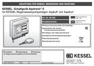
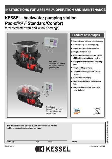
INSTRUCTIONS FOR ASSEMBLY, OPERATION AND MAINTENANCE<br />
<strong>KESSEL</strong> - <strong>backwater</strong> <strong>pumping</strong> <strong>station</strong><br />
Pumpfix ® F <strong>Standard</strong>/<strong>Comfort</strong><br />
for wastewater with and without sewage<br />
The installation and service of this unit should be carried<br />
out by a licensed professional servicer<br />
Name/Sign Date Town<br />
Stand 04/2011<br />
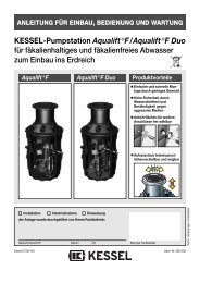
Fig. shows:<br />
Pumpfix ® F <strong>Comfort</strong><br />
for installation in the<br />
ground plate<br />
Fig. shows:<br />
Pumpfix ® F <strong>Standard</strong><br />
for installation in an<br />
exposed pipe<br />
Product advantages<br />
For wastewater with and without sewage<br />
Backwater flap and draining pump<br />
Simple installation in through pipes<br />
Plug & play control unit<br />
Control unit with self-diagnosis system<br />
(SDS) with integrated battery back-up<br />
Straightforward replacement of wearing<br />
parts<br />
Simple tool-free servicing<br />
Additional advantages of the Komfort<br />
version:<br />
Control unit with display<br />
Motor-driven locking of the <strong>backwater</strong><br />
flap<br />
Integrated drain function for surface<br />
water drainage<br />
LGA<br />
Landesgewerbeamt Bayern<br />
Bauart<br />
geprüft geprüft<br />
und und überwacht<br />
überwacht<br />
Stamp<br />
mit Sicherheit<br />
geprüfte Qualität<br />
ID-Number 010-843EN<br />
Subject to technical amendments
Table of contents<br />
1. Safety instructions ........................................................................................................... Page 2<br />
2. General points 2.1 Use ..................................................................................................... Page 3<br />
2.2 Scope of supply.................................................................................. Page 3<br />
2.3 Installation procedure ......................................................................... Page 3<br />
2.4 General instructions about the installation of <strong>backwater</strong> valves ......... Page 3<br />
3. Installation 3.1 Installation in the ground plate............................................................ Page 4<br />
3.2 Recessed installation in the ground plate........................................... Page 4<br />
3.3 Ventilation connection ........................................................................ Page 4<br />
3.4 Installation in an exposed wastewater pipe ........................................ Page 5<br />
3.5 Installation in water load..................................................................... Page 5<br />
3.6 Special features of Pumpfix ® F <strong>Comfort</strong> ............................................. Page 5<br />
3.7 Set-up................................................................................................. Page 5<br />
4. Service and maintenance 4.1 Service ..................................................................................................... Page 6<br />
4.2 Maintenance............................................................................................. Page 6<br />
4.2.1 Mounting the two covers........................................................................... Page 6<br />
4.3 Test ......................................................................................................... Page 6<br />
4.3.1 Test <strong>Standard</strong> ........................................................................................... Page 6<br />
4.3.2 Test <strong>Comfort</strong> ............................................................................................. Page 6<br />
4.4 Pump removal .......................................................................................... Page 7<br />
4.5 Motor installation ...................................................................................... Page 7<br />
4.6 Removing motor ground installation......................................................... Page 7<br />
4.7 How the emergency valve works.............................................................. Page 8<br />
4.7.1 <strong>Standard</strong>................................................................................................... Page 8<br />
4.7.2 <strong>Comfort</strong>..................................................................................................... Page 8<br />
4.8 Servicing the ventilation ........................................................................... Page 8<br />
5. Spare parts 5.1 <strong>Standard</strong>............................................................................................. Page 9<br />
5.2 <strong>Comfort</strong>............................................................................................... Page 10<br />
6. Warranty ......................................................................................... ................. Page 11<br />
7. Commissioning protocol for the installer ........................................................................................................... Page 12<br />
8. Commissioning protocol for the installation company...................................................................................... Page 14<br />
Dear customer,<br />
Before you put your <strong>backwater</strong> <strong>pumping</strong><br />
<strong>station</strong> Pumpfix ® F into operation,<br />
please read through the installation instructions<br />
carefully and follow them.<br />
Check first whether the system has arrived<br />
undamaged. In the event of transport<br />
damage, please follow the instructions in<br />
chapter 6 “Warranty”.<br />
1. Safety instructions:<br />
During installation, operation, maintenance<br />
or repair of the system, the regulations<br />
for the prevention of accidents, the pertinent<br />
DIN and VDE standards and directives,<br />
as well as the directives of the local<br />
power supply industry must be heeded.<br />
Before putting the device into operation,<br />
make sure through professional examination<br />
that the necessary protective features<br />
are available. Grounding, neutral, residual<br />
current-operated protective circuit etc.<br />
must correspond to the requirements of<br />
the local power supply industry.<br />
The system must not be operated in po-<br />
1. Safety instructions<br />
tentially explosive areas.<br />
The system contains electric charges and<br />
controls rotating mechanical system components.<br />
Non-compliance with the operating<br />
instructions may result in considerable<br />
damage to property, personal injuries<br />
or even fatal accidents.<br />
The system must be disconnected<br />
from the mains or made currentless<br />
before any work is carried<br />
out on it.<br />
It must be ensured that the electric cables<br />
as well as all other electrical system<br />
equipment are in a faultless condition. In<br />
case of damage, the system may on no<br />
account be put into operation or must be<br />
stopped immediately.<br />
The system must be inspected and serviced<br />
according to DIN 1986 to maintain its<br />
operational ability.<br />
We recommend that you conclude a servicing<br />
contract with your installation company.<br />
2<br />
No repairs or maintenance work may be<br />
carried out during a <strong>backwater</strong> situation or<br />
if a <strong>backwater</strong> situation is imminent. The<br />
<strong>backwater</strong> flaps and the locking lever always<br />
have to be able to be moved freely.<br />
Note:<br />
No system components may be installed<br />
in protection zone 0 or 1 in accordance<br />
with DIN VDE 0100 701. In the case of<br />
flush-to-floor showers, zone 1 is defined<br />
as with a radius of 1.20 m (projected area<br />
on the floor) around the water intake point.<br />
Deviating local regulations must be taken<br />
into account.<br />
The regulations set out by the directives<br />
VDE 0100, VDE 01107, IEC or by the local<br />
power supply industry must be heeded.<br />
The control unit must not be installed in<br />
rooms where there is an explosion hazard.<br />
For the operation of this system,<br />
these instructions and instructions no.<br />
010-846 must be used together!
2.1 Use<br />
The <strong>KESSEL</strong> <strong>backwater</strong> <strong>pumping</strong> <strong>station</strong><br />
Pumpfix ® F has been designed for through<br />
wastewater pipes that have soiled water<br />
pipes as well as toilets and urinals connected<br />
to them. This guarantees the safe draining<br />
of draining spots below the <strong>backwater</strong><br />
level even during <strong>backwater</strong>. The pump only<br />
works during <strong>backwater</strong> and pumps the soiled<br />
water into the sewage channel against<br />
the <strong>backwater</strong>. During <strong>backwater</strong>-free operation,<br />
the soiled water is discharged into<br />
the sewage channel through the natural<br />
gradient.<br />
Pumpfix ® does not provide protection<br />
against rats! If there is a rat hazard, the system<br />
must be protected from damage onsite.<br />
A rat protection flap is available as an option<br />
and prevents damage caused by gnawing<br />
to a large extent (<strong>Standard</strong> only).<br />
Important:<br />
Pre-condition for trouble-free operation is<br />
• Sufficient gradient in the draining pipes<br />
(note: there is a gradient of 9 mm between<br />
feed and drain with <strong>Pumpfix®</strong> F)<br />
• A high share oSufficient gradient in the<br />
draining pipes (note: there is a gradient<br />
of 9 mm between feed and drain with<br />
<strong>Pumpfix®</strong> F)<br />
• A high share of water in the wastewater<br />
to optimise the self-cleaning effect<br />
• Correct routing and ventilation of the<br />
feed pipe in accordance with DIN EN<br />
12056 / DIN 1986-100<br />
• Use with greasy wastewater only possible<br />
with increased maintenance and<br />
cleaning efforts<br />
• Rain surfaces up to max. 20 m 2<br />
Installation of a <strong>backwater</strong> valve in the right place<br />
Backwater protection<br />
2. General<br />
2.2 Scope of supply<br />
The scope of supply of the <strong>KESSEL</strong> <strong>backwater</strong><br />
<strong>pumping</strong> <strong>station</strong> Pumpfix ® F is<br />
made up of the drain body with pump and<br />
<strong>backwater</strong> valve and the electric packages.<br />
The electric packages are made up of:<br />
<strong>Standard</strong><br />
1. The optical probe<br />
2. A control unit (mains connection 230 V,<br />
50 Hz, protective rating IP 54) with battery<br />
back-up (2 x 9V) for alarm message<br />
in the event of a power failure.<br />
3. An installation and operating manual<br />
<strong>Comfort</strong><br />
1. Two optical probes and the drive motor<br />
2. One control unit with display (mains<br />
connection 230 V, 50 Hz, protective rating<br />
IP54) with battery back-up (2 x 9V) for<br />
alarm message in the event of a power<br />
supply.<br />
3. An installation and operating manual<br />
2.3 Installation procedure<br />
During the construction phase only the drain<br />
body is installed and connected in accordance<br />
with chapter 3. Usually, the power<br />
connection (chapter 4) and subsequent initial<br />
operation (chapter 5) cannot be carried<br />
out directly. Please connect the electric system<br />
components (pump, probes, motor<br />
and control unit, depending on the variant)<br />
when you put the <strong>KESSEL</strong> <strong>backwater</strong> <strong>pumping</strong><br />
<strong>station</strong> <strong>Pumpfix®</strong> F into operation. Until<br />
this point, the enclosed electric package<br />
and the control unit must be kept stored in a<br />
clean and dry place. Only remove the plug<br />
end plates when the system is put into operation.<br />
Care must be taken that the system is always<br />
sealed with an upper cover section<br />
and cover or protective hood when set up as<br />
Right!<br />
Backwater<br />
level<br />
3<br />
Backwater protection<br />
a free-standing device in order to prevent<br />
soiling of the system.<br />
Caution: The pump is secured by a transportation<br />
safety tape that has to be removed<br />
before initial operation.<br />
2.4 General instructions about the installation<br />
of <strong>backwater</strong> valves<br />
According to DIN EN 12056 <strong>backwater</strong> valves<br />
may not be used to protect all the draining<br />
points of a building - including those<br />
above the <strong>backwater</strong> level (street level) - because<br />
if the <strong>backwater</strong> valve is closed, the<br />
wastewater from above can no longer be<br />
drained into the sewage pipe but will - according<br />
to the principle of communicating<br />
pipes - escape from the drainage points furthest<br />
below the <strong>backwater</strong> level first (usually<br />
basement rooms) and thus flood the basement.<br />
Only draining points below the <strong>backwater</strong><br />
level may be protected against <strong>backwater</strong>.<br />
All draining points above the <strong>backwater</strong><br />
level must be discharged into the sewage<br />
pipe with free gradient past the <strong>backwater</strong><br />
valve.<br />
Consequence: separate pipe routing.<br />
Domestic wastewater above the <strong>backwater</strong><br />
level can thus rise up to a maximum of street<br />
level inside the downpipe without flooding<br />
the basement.<br />
Rainwater must never be discharged via<br />
<strong>backwater</strong> valves.<br />
Installation of a <strong>backwater</strong> valve in the wrong place<br />
Wrong!<br />
Backwater<br />
level
Please note:<br />
DIN EN 12056 must always be heeded when<br />
routing the base pipes. Downpipes must always<br />
be introduced downstream from the<br />
<strong>Pumpfix®</strong> F (about 1m). In addition, a stilling<br />
section must be observed upstream and downstream<br />
of the FKA (at least 1 m). During installation<br />
of the <strong>backwater</strong> valve, care must be<br />
taken that there is a sufficient gap to the wall<br />
for maintenance work to be carried out. The<br />
KG pipe must not be connected directly to the<br />
drain body but only to the muff.<br />
Caution: During installation pay attention<br />
to the direction of flow arrows on the product.<br />
3.1 Kessel <strong>backwater</strong> <strong>pumping</strong> <strong>station</strong><br />
Pumpfix ® F for installation in the<br />
ground plate<br />
DThe drain body of the <strong>KESSEL</strong>-<strong>Pumpfix®</strong> F<br />
must be aligned horizontally (see Fig. 1).<br />
For connection of the electric cables of probe<br />
and pump, a cable conduit (at least DN 50,<br />
Kessel recommends 2 x 45° bends) must be<br />
provided. A second probe cable and motor<br />
connection cable must be connected for the<br />
Komfort variant. For this, a cable conduit (at<br />
least DN 70, Kessel recommends 2 x 45°<br />
bends) must be planned. To do this, lay the<br />
cable conduit to at least finished flooring height<br />
(see Fig. 2) and insert in the cable duct in the<br />
adapter of the <strong>KESSEL</strong> <strong>Pumpfix®</strong> F (cable<br />
conduit should protrude about 2 cm into the interior<br />
- tightness (Fig. 5). Changes of direction<br />
must be laid with bends of max. 45°. To guarantee<br />
proper aerating and venting of the pump<br />
chamber, the cable conduit must not be sealed<br />
airtight. Insert the enclosed profile lip seal into<br />
the adapter groove and grease this. Then<br />
mount the upper cover section (see Fig. 3).<br />
Thanks to the telescopic design of the upper<br />
cover section, the <strong>KESSEL</strong>-<strong>Pumpfix®</strong> F can be<br />
adapted exactly to the prevailing installation<br />
depth. Ground slopes of up to 5° can be compensated.<br />
The upper cover section can also be<br />
turned to align the cover to the tile pattern, for<br />
example (see Fig. 4). The seal must be<br />
checked for a good fit after adjustment.<br />
CAUTION:<br />
The upper cover section must be shortened<br />
to the necessary size to achieve minimum<br />
installation depth. If necessary,<br />
recesses must be cut out of the upper<br />
cover section near the cable conduit and<br />
the ventilation pipe. Maximum groundwater<br />
resistance is 2 m. Following final<br />
alignment of the upper cover section, a<br />
recess may have to be introduced near<br />
the cable duct to enable the cable to be<br />
pulled out again during later inspections<br />
(see Fig. 5).<br />
The lip seal must be fitted in the cover plate.<br />
Care must be taken that the sealing lip and<br />
3. Installation<br />
centring lug are facing upwards during installation.<br />
The centring lug must be placed in the<br />
recess (see Fig. 6).<br />
During installation, make sure that the function<br />
of units in the chamber is not impaired by construction<br />
material.<br />
Installation of covers with a choice of finishes<br />
(tile height max. 15 mm).<br />
With the covers with a choice of finishes, tiles<br />
or natural stone can be inserted in the cover on<br />
site, so that they can be matched to the roomʼs<br />
flooring. Products e.g. from PCI, Schomburg,<br />
Deitermann are suitable for tile laying. To<br />
achieve straightforward processing and adhesion,<br />
we recommend the following procedure:<br />
Tile laying:<br />
a) aPrime the cover plate e.g. with PCI primer<br />
303. Following the respective flash-off time,<br />
lay the tiles with silicone. This type of laying<br />
is particularly suitable for thinner tiles since<br />
the base can be filled up to the required<br />
height.<br />
b) Laying the tiles e.g. using PCI Silcoferm S<br />
(self-adhesive silicone). This allows a thin<br />
adhesive bed to be used, particularly good<br />
for thicker tiles.<br />
Laying natural stone:<br />
(marble, granite, agglo-marble):<br />
a) Prime the cover plate e.g. with PCI primer<br />
303. Lay the natural stone panels using e.g.<br />
PCI-Carralit..<br />
b) Laying the natural stone panels using e.g.<br />
PCI-Carraferm (special silicone for natural<br />
stone). Areas of application analogue to<br />
“Laying tiles”.<br />
3.2 Recessed installation in the ground<br />
plate<br />
(order no. 83071). Chapter 3.4 must be heeded<br />
for installation in water load.<br />
Depending on the installation depth, one or<br />
max. two extension pieces can be used between<br />
the upper cover section and the adapter.<br />
The respective seals must be greased accordingly.<br />
Please note that with recessed installation you<br />
still have to be able to reach down to the drain<br />
body for maintenance purposes.<br />
3.3. Ventilation connection<br />
<strong>Pumpfix®</strong> F is fitted as standard with a ventilation<br />
valve with activated carbon filter. Alternatively,<br />
ventilation according<br />
to standard<br />
can be connected. For<br />
this, the ventilation<br />
valve can be removed<br />
and connected directly<br />
to a ventilation pipe<br />
(to the roof).<br />
4<br />
Fig. 1<br />
fig. 2<br />
Fig. 3<br />
Fig. 4<br />
fig. 5<br />
Fig. 6
3.4 Installation in an exposed wastewater<br />
pipe<br />
The version for free-standing set-up is delivered<br />
with a protective hood to prevent damage to<br />
the components following commissioning. Fig.<br />
7 shows the cable ducts – 1 or 2 (depending on<br />
the variant).<br />
3.5 Installation in water load<br />
(Seal set art. no. 83023<br />
Fig. 7<br />
If the valve is to be installed in water load,<br />
the flange serves as the necessary sealing<br />
level for a white or black tub (see Figure).<br />
For this purpose, seal sheeting is clamped<br />
between the plastic counterflange and the<br />
compression seal flange integrated on the<br />
drain body, and screwed together using the<br />
enclosed screws.<br />
The sheeting used on site can be used as<br />
seal sheeting. For installation in a waterproof<br />
white tub, <strong>KESSEL</strong> also has matching<br />
seal sheeting available made of natural rubber<br />
NK/SBR, where the bore holes for the<br />
screws have already been cut out (see Fig.<br />
8).<br />
If it is necessary to perforate the waterproof<br />
concrete tub to connect feed pipes, cable<br />
conduits etc., these holes must also be set<br />
up waterproof. Maximum groundwater resistance<br />
is 2 m.<br />
Installation example “black tub”<br />
BWS*<br />
4<br />
Tiles Fliesen<br />
Screed Estrich<br />
Insulation Dämmung<br />
Concrete Betonboden floor<br />
Protective Schutzbeton concrete<br />
Sealing Abdichtung<br />
Underfloor Unterbeton<br />
➀ <strong>KESSEL</strong>-<strong>Pumpfix®</strong> F, Staufix® FKA, Staufix® SWA, Controlfix<br />
➁ Compression seal flange with seal set art. no. 83023<br />
➂ Extension art. no. 83071<br />
➃ Adapter DN 100 with compression seal flange made of stainless<br />
steel art. no. 27198<br />
2<br />
3<br />
1<br />
3. Einbau<br />
Installation with extension (order no.<br />
83071).<br />
Use of the extension allows the flange<br />
height to be individually adjusted. The<br />
attachment must be shortened to the required<br />
height if necessary.<br />
3.6 Special features of Pumpfix ® F<br />
<strong>Comfort</strong><br />
Pumpfix F Komfort has an integrated draining<br />
function for surface water drainage.<br />
3.7 Set-up<br />
Connection of the draining function to the<br />
feed cover is via the enclosed draining<br />
connection. Insert the draining connection<br />
into the prescribed opening and lock using<br />
the one-handed quick-action closure.<br />
Depending on installation depth (installation<br />
depth of the upper cover section), the<br />
draining connection must be shortened to<br />
the respective length (see Fig. 9) or extended<br />
using HT-pipe DN 70 if recessed installation<br />
using extension (art. no. 83071) is<br />
used.<br />
5<br />
BWS *<br />
Fig 9<br />
4<br />
5<br />
Pumpfix<br />
S<br />
® F <strong>Comfort</strong><br />
Installation example “white tub”<br />
Seal seat (83023)<br />
• Counterflange • Sealing sheet<br />
Fig. 8<br />
Pressdichtungsflansch<br />
Tiles Fliesen<br />
Screed Estrich<br />
Insulation Dämmung<br />
Concrete Betonboden floor<br />
➄ Elastomer sealing sheet art. no. 27159<br />
➅ Upper cover section with plastic cover plate<br />
➆ Control unit<br />
➇ Locking lever<br />
2<br />
➇<br />
➅<br />
1<br />
➆<br />
WU-Beton
4.1 Service<br />
The system must be checked once every<br />
month by the operator through observation<br />
of the switching routine for operational<br />
ability and leaks.<br />
• Close emergency valve or with Komfort:<br />
press test key to carry out functional test<br />
on <strong>backwater</strong> valve -> valve closes<br />
• Allow water to flow in<br />
• Wait until level-LED + pump trigger.<br />
• Switch off water feed<br />
• Switch off level-LED and wait for pump<br />
• Open hand lever (vertical position OPEN)<br />
-> <strong>Standard</strong><br />
Komfort: Please note that the <strong>backwater</strong><br />
valve must be open after the inspection<br />
has been completed.<br />
The pump should be checked at regular intervals.<br />
If operational noises increase,<br />
<strong>pumping</strong> capacity decreases or there are<br />
vibrations in the pipeline system, the pump<br />
housing and impeller must be checked for<br />
any stubborn soiling or wear.<br />
4.2 Maintenance (at least every six<br />
months)<br />
CAUTION: Disconnect the unit from the<br />
mains during all servicing work! Heed<br />
safety instructions! No warranty will be<br />
granted in the event of insufficient<br />
maintenance! All the servicing and<br />
maintenance work described below<br />
may only be carried out by authorised<br />
qualified personnel. Repairs may only<br />
be carried out by the manufacturer.<br />
DIN 1986, part 3, must be heeded during<br />
maintenance work on systems. Maintenance<br />
work must be carried out at least every<br />
six months by authorised qualified staff.<br />
The following tasks have to be carried out:<br />
• Visual inspection of the complete system<br />
• Thorough cleaning of the complete system<br />
and the pump<br />
• Check on the complete system and pump<br />
housing for external damage and visible<br />
wear<br />
• Check on the pump for free movement,<br />
wear and deposits<br />
• Check the connection cables for mechanical<br />
damage and wear<br />
• Check the seal connections for leaks and<br />
any recognisable wear<br />
• Insulation test on the pump motor<br />
• Check the control unit for damage and<br />
soiling<br />
• Check and clean the ventilation valve<br />
• Clean the optical probe<br />
4. Service and maintenance<br />
We recommend these jobs after longer periods<br />
of standstill or intermediate storage, too,<br />
as well as after longer or frequent occurrences<br />
of <strong>backwater</strong>. If problems should occur<br />
that cannot be eliminated, please contact<br />
the specialist company who carried out the<br />
installation (see stamp on cover sheet) if in<br />
doubt.<br />
4.2.1 Mounting the two covers (see Fig.<br />
12, 13, 14)<br />
Insert the covers on one side, push the other<br />
side down and lock in place using the locking<br />
levers. During installation of the overflow<br />
cover the red flap lever or the motor flap position<br />
must always be “CLOSED”<br />
4.3 Test<br />
<strong>Standard</strong> <strong>Comfort</strong><br />
a) Pull the insertable part out<br />
b) Clean all the parts<br />
c) Check the seals<br />
d) Apply lubricant (e.g. fittings grease)<br />
to the outside of the seals of the insertable<br />
parts as well as the guide<br />
parts of the flap valves<br />
6<br />
e) Insert the insertable part exactly<br />
f) Make sure the attachment clips are in<br />
place properly!<br />
g) Heed cover installation 4.2.1<br />
h) Carry out functional test in accordance<br />
with instruction manual 010-846.<br />
Abb. 12<br />
4.3.1 Test <strong>Standard</strong><br />
1. Hold the pump probe into the water "On" level Level-LED lit<br />
Pump starts Pump-LED lit<br />
4.3.2 Test <strong>Comfort</strong><br />
1. Hold the motor probe into the water Flap closes Backwater-LED flashes<br />
Flap-LED flashes<br />
Flap closed Backwater-LED flashes<br />
Flap-LED lit<br />
2. Hold the pump probe into the water Pump starts Pump-LED lit
5.1 <strong>Standard</strong><br />
Pumpfix ® F for installation in an exposed wastewater pipe<br />
All spare parts can be purchased from a specialist company.<br />
Designation Art. no.<br />
➀ Pumpfix ® F-control unit <strong>Standard</strong> IP 54 28073<br />
a) Additional board for potential-free contact 80072<br />
b) Remove signal generator 20 m 20162<br />
c) Battery 9V (2 units required) 197-081<br />
➁ Optical probe IP 68 (5 m, inc. adapters) 80888<br />
➂ Cover pump feed side (without outlet function) 28052<br />
➃ Pumpfix ® F-cover <strong>Standard</strong> outlet side 28053<br />
➄ Pumpfix ® F-pump IP 68 (5m, inc. plug) 28351<br />
➅ Ventilation complete 28060<br />
a) Activated carbon filter 28061<br />
➆ Mechanical flap 80033<br />
➇ Insertion part for mechanical flap 80034<br />
➈ Hood 80031<br />
Transition piece 83032<br />
Seal set II 70319<br />
Pumpfix ® F for installation in the ground plate<br />
All spare parts can be purchased from a specialist company.<br />
Designation Art. no.<br />
➀ Pumpfix ® F-control unit <strong>Standard</strong> IP 54 28073<br />
a) Additional board for potential-free contact 80072<br />
b) Remove signal generator 20 m 20162<br />
c) Battery 9V (2 units required) 197-081<br />
➁ Optical probe IP 68 (5 m, inc. adapters) 80888<br />
➂ Cover pump feed side (without outlet function) 28052<br />
➃ Pumpfix ® F-cover <strong>Standard</strong> outlet side 28053<br />
➄ Pumpfix ® F-pump IP 68 (5m, inc. plug) 28351<br />
➅ Ventilation complete 28060<br />
6a) Activated carbon filter 28061<br />
➆ Mechanical flap 80033<br />
➇ Insertion part for mechanical flap 80034<br />
Seal set II 70319<br />
5. Spare parts<br />
9<br />
➂<br />
<br />
<br />
<br />
➄<br />
<br />
➁<br />
<br />
<br />
a<br />
➆<br />
<br />
a<br />
<br />
➀<br />
a,b,c<br />
➀<br />
a,b,c
5.2 <strong>Comfort</strong><br />
Pumpfix ® F for installation in an exposed wastewater pipe<br />
All spare parts can be purchased from a specialist company.<br />
Designation Art. no.<br />
➀ Pumpfix ® F-control unit Komfort IP 54 28071<br />
a) Additional board for potential-free contact 80072<br />
b) Remove signal generator 20 m 20162<br />
c) Battery 9V (2 units required) 197-081<br />
➁ Optical probe IP 68 (5 m, inc. adapters) 80888<br />
➂ Cover pump feed side (without outlet function) 28052<br />
➃ Pumpfix ® F-cover Komfort outlet side 28056<br />
➄ Pumpfix ® F-pump IP 68 (5m, inc. plug) 28351<br />
➅ Ventilation complete 28060<br />
a) Activated carbon filter 28061<br />
➆ Motor-driven flap 80038<br />
➇ Insertion part for motor-driven flap 80039<br />
➈ Hood 83031<br />
Transition piece 83032<br />
Drive motor IP 68 (5m cable) 80076<br />
Seal set II 70319<br />
Pumpfix ® F for installation in the ground plate<br />
All spare parts can be purchased from a specialist company.<br />
Designation Art. no.<br />
➀ Pumpfix ® F-control unit Komfort IP 54 28071<br />
a) Additional board for potential-free contact 80072<br />
b) Remove signal generator 20 m 20162<br />
c) Battery 9V (2 units required) 197-081<br />
➁ Optical probe IP 68 (5 m, inc. adapters) 80888<br />
➂ Cover pump feed side (with outlet function) 28054<br />
➃ Pumpfix ® F-cover Komfort outlet side 28056<br />
➄ Pumpfix ® F-pump IP 68 (5m, inc. plug) 28351<br />
➅ Ventilation complete 28060<br />
6a) Activated carbon filter 28061<br />
➆ Motor-driven flap 80038<br />
➇ Insertion part for motor-driven flap 80039<br />
Drive motor IP 68 (5m cable) 80076<br />
Seal set II 70319<br />
5. Spare parts<br />
10<br />
➂<br />
<br />
<br />
<br />
<br />
➁<br />
➄<br />
<br />
<br />
<br />
<br />
➁<br />
a<br />
<br />
➆<br />
<br />
a<br />
<br />
➀<br />
a,b,c<br />
➀<br />
a,b,c
1. In the case that a <strong>KESSEL</strong> product is defective,<br />
<strong>KESSEL</strong> has the option of repairing<br />
or replacing the product. If the product<br />
remains defective after the second<br />
attempt to repair or replace the product or<br />
it is economically unfeasible to repair or<br />
replace the product, the customer has<br />
the right to cancel the order / contract or<br />
reduce payment accordingly. <strong>KESSEL</strong><br />
must be notified immediately in writing of<br />
defects in a product. In the case that the<br />
defect is not visible or difficult to detect,<br />
<strong>KESSEL</strong> must be notified immediately in<br />
writing of the defect as soon as it is discovered.<br />
If the product is repaired or replaced,<br />
the newly repaired or replaced<br />
product shall receive a new warranty<br />
identical to that which the original (defective)<br />
product was granted. The term defective<br />
product refers only to the product<br />
6. Warranty<br />
or part needing repair or replacement<br />
and not necessarily to the entire product<br />
or unit. <strong>KESSEL</strong> products are warranted<br />
for a period of 24 month. This warranty<br />
period begins on the day the product is<br />
shipped form <strong>KESSEL</strong> to its customer.<br />
The warranty only applies to newly manufactured<br />
products. Additional information<br />
can be found in section 377 of the<br />
HGB.<br />
In addition to the standard warranty,<br />
<strong>KESSEL</strong> offers an additional 20 year warranty<br />
on the polymer bodies of class I / II<br />
fuel separators, grease separators, inspection<br />
chambers, wastewater treatment<br />
systems and rainwater storage<br />
tanks. This additional warranty applies to<br />
the watertightness, usability and structural<br />
soundness of the product.<br />
11<br />
A requirement of this additional warranty<br />
is that the product is properly installed<br />
and operated in accordance with the valid<br />
installation and user's manual as well as<br />
the corresponding norms / regulations.<br />
2. Wear and tear on a product will not be<br />
considered a defect. Problems with products<br />
resulting from improper installation,<br />
handling or maintenance will also be considered<br />
a defect.<br />
Note: Only the manufacturer may open<br />
sealed components or screw connections.<br />
Otherwise, the warranty may become<br />
null and void<br />
01.06.2010
7. Commissioning Protocol for installer<br />
Separator Type: __________________________________________________________<br />
Day / Hour __________________________________________________________<br />
Project description /Building services supervisor __________________________________________________________<br />
Address __________________________________________________________<br />
Telephone / Fax __________________________________________________________<br />
Builder __________________________________________________________<br />
Address __________________________________________________________<br />
Telephone / Fax __________________________________________________________<br />
Planner __________________________________________________________<br />
Address __________________________________________________________<br />
Telephone / Fax __________________________________________________________<br />
Contracted plumbing company __________________________________________________________<br />
Address __________________________________________________________<br />
Telephone / Fax __________________________________________________________<br />
<strong>KESSEL</strong>-Commissions no.:<br />
System operator /owner __________________________________________________________<br />
Address __________________________________________________________<br />
Telephone / Fax __________________________________________________________<br />
User __________________________________________________________<br />
Address __________________________________________________________<br />
Telephone / Fax __________________________________________________________<br />
Person of delivery __________________________________________________________<br />
Other remarks __________________________________________________________<br />
The system operator, and those responsible, were present during the commissioning of this system.<br />
____________________________ ____________________________ ____________________________<br />
Place and date Signature owner Signature user<br />
12
Notice<br />
13
8. Commissioning Protocol for installation company<br />
Handover certificate (copy for the company carrying out the installation)<br />
❏ The initial operation and instruction was carried out in the presence of the person authorised to perform the acceptance<br />
and the system operator.<br />
❏ The system operator/person authorised to perform the acceptance was informed about the obligation to service<br />
the product according to the enclosed operating instructions.<br />
❏ Initial operation and instruction were not carried out.<br />
The client/ person responsible for initial operation was handed the following components and/or product components<br />
Initial operation and instruction is being carried out by (company, address, contact, phone)<br />
The exact coordination of the dates for initial operation/instruction is being carried out by the system operator and person<br />
responsible for initial operation.<br />
Place, date Signature of person Signature of system operator Signature of the company<br />
authorised to perform acceptance carrying out the installation work<br />
14
❑ Backwater protection<br />
❑ Lifting Stations and pumps<br />
❑ Drains and shower channels<br />
❑ Separators<br />
-Grease Separators<br />
-Oil-/Fuel-/Coalescence<br />
Separators<br />
-Starch Separators<br />
-SedimentSeparators<br />
❑ Septic Systems<br />
❑ Inspection Chambers<br />
❑ Rainwater Management<br />
Systems