SL-M660 - Canyon
SL-M660 - Canyon
SL-M660 - Canyon

You also want an ePaper? Increase the reach of your titles
YUMPU automatically turns print PDFs into web optimized ePapers that Google loves.
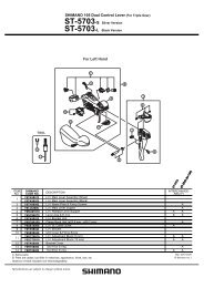
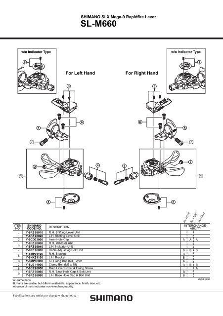
ITEM<br />
NO.<br />
1<br />
2<br />
3<br />
4<br />
5<br />
6<br />
7<br />
8<br />
9<br />
1<br />
SHIMANO<br />
CODE NO.<br />
Y-6PZ 98010<br />
Y-6PZ 98020<br />
Y-6CD 33000<br />
Y-6PZ 98030<br />
Y-6PZ 98040<br />
Y-6PZ 98070<br />
Y-6MP 01100<br />
Y-6NX 51100<br />
Y-6MP 98080<br />
Y-8U9 14000<br />
Y-6CZ 98050<br />
Y-6PZ 98080<br />
Y-6PZ 98090<br />
DESCRIPTION<br />
R.H. Shifting Lever Unit<br />
L.H. Shifting Lever Unit<br />
Inner Hole Cap<br />
R.H. Indicator Unit<br />
L.H. Indicator Unit<br />
Cable Adjustting Bolt Unit<br />
R.H. Bracket<br />
L.H. Bracket<br />
<strong>SL</strong> Fixing Bolt (M4) 2pcs.<br />
Clamp Bolt (M6 x 15)<br />
Main Lever Cover & Fixing Screw<br />
R.H. Base Hole Cap & Bolt Unit<br />
L.H. Base Hole Cap & Bolt Unit<br />
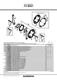
A: Same parts.<br />
B: Parts are usable, but differ in materirals, appearance, finish, size, etc.<br />
Absence of mark indicates non-interchangeability.<br />
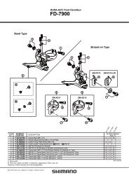
SHIMANO <strong>SL</strong>X Mega-9 Rapidfire Lever<br />
<strong>SL</strong>-<strong>M660</strong><br />
w/o Indicator Type w/o Indicator Type<br />
9<br />
7<br />
2<br />
5<br />
For Left Hand For Right Hand<br />
3 3<br />
6<br />
4<br />
8 8<br />
4<br />
6<br />
5<br />
A<br />
B<br />
B<br />
B<br />
A<br />
A<br />
B<br />
B<br />
7<br />
2<br />
<strong>SL</strong>-M770<br />
<strong>SL</strong>-M580<br />
9<br />
1<br />
<strong>SL</strong>-M530<br />
INTERCHANGE-<br />
ABILITY<br />
A<br />
B<br />
B<br />
A<br />
B<br />
B<br />
A<br />
0803-2797
General Safety Information<br />
WARNING<br />
• Use neutral detergent to clean the chain. Do not use alkali-based or acid based detergent such as rust cleaners as it may result<br />
in damage and/or failure of the chain.<br />
• Use the reinforced connecting pin only for connecting the narrow type of chain.<br />
• There are two different types of reinforced connecting pins available. Be sure to check the table below before selecting which<br />
pin to use.<br />
If connecting pins other than reinforced connecting pins<br />
are used, or if a reinforced connecting pin or tool which<br />
is not suitable for the type of chain is used, sufficient<br />
connection force may not be obtained, which could<br />
cause the chain to break or fall off.<br />
• If it is necessary to adjust the length of the chain due<br />
to a change in the number of sprocket teeth, make the<br />
cut at some other place than the place where the chain<br />
has been joined using a reinforced connecting pin or an end pin. The chain will be damaged if it<br />
is cut at a place where it has been joined with a reinforced connecting pin or an end pin.<br />
• Be careful not to let the cuffs of your clothes get caught in the chain while riding, otherwise you<br />
may fall off the bicycle.<br />
• Check that the tension of the chain is correct and that the chain is not damaged. If the tension<br />
is too weak or the chain is damaged, the chain should be replaced. If this is not done, the chain<br />
may break and cause serious injury.<br />
• Use a front chainwheel which is compatible with 9-speed chains in conjunction with Shimano CN-7701,<br />
CN-HG93 and CN-HG73 chains. If a chainwheel for an 8-speed chain or less is used, front chainwheel gear shifting problems<br />
may occur, or the chain pins might fall out, causing the chain to break.<br />
• The two left crank arm mounting bolts should be tightened alternately in stages rather than each bolt being fully tightened all at<br />
once. Use a torque wrench to check that the final tightening torques are within the range of 12 - 15 N·m.<br />
Furthermore, after riding approximately 100 km (60 miles), use a torque wrench to re-check the tightening torques.<br />
It is also important to periodically check the tightening torques.<br />
If the tightening torques are too weak or if the mounting bolts are not tightened alternately in stages, the left crank arm may<br />
come off and the bicycle may fall over, and serious injury may occur as a result.<br />
• Check that there are no cracks in the crank arms before riding the bicycle. If there are any cracks, the crank arm may break and<br />
you may fall off the bicycle.<br />
• If the inner cover is not installed correctly, the axle may rust and become damaged, and the bicycle may fall over and serious injury<br />
may occur as a result.<br />
• Obtain and read the service instructions carefully prior to installing the parts. Loose, worn or damaged parts may cause the<br />
bicycle to fall over and serious injury may occur as a result. We strongly recommend only using genuine Shimano replacement<br />
parts.<br />
• Obtain and read the service instructions carefully prior to installing the parts. If adjustments are not carried out correctly, the<br />
chain may come off and this may cause you to fall off the bicycle which could result in serious injury.<br />
• Read these Technical Service Instructions carefully, and keep them in a safe place for later reference.<br />
Chain<br />
9-speed super narrow<br />
chain such as<br />
CN-7701 / CN-HG93<br />
8- / 7- / 6-speed narrow<br />
chain such as<br />
CN-HG50 / CN-HG40<br />
Reinforced<br />
connecting pin<br />
Chain tool<br />
TL-CN32 / TL-CN27<br />
TL-CN32 / TL-CN27<br />
Technical Service Instructions SI-6PZFA-002<br />
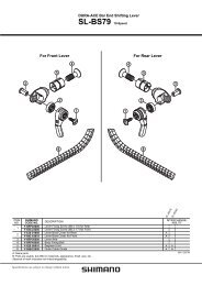
Front Drive System<br />
In order to realize the best performance, we recommend that the following combination be used.<br />
Series <strong>SL</strong>X<br />
Rapidfire (Shifting lever) <strong>SL</strong>-<strong>M660</strong><br />
Outer casing SIS-SP41<br />
Type Triple<br />
Front derailleur FD-<strong>M660</strong> / FD-M661 / FD-<strong>M660</strong>-E<br />
Front chainwheel FC-<strong>M660</strong><br />
Chain CN-HG73<br />
Bottom bracket cable guide SM-SP17<br />
This service instruction explains how to use and<br />
maintain the Shimano bicycle parts which have<br />
been used on your new bicycle.<br />
For any questions regarding your bicycle or other<br />
matters which are not related to Shimano parts,<br />
please contact the place of purchase or the<br />
bicycle manufacturer.<br />
6.5mm<br />
7.1mm<br />
Silver<br />
Black<br />
Reinforced Connecting Pin<br />
End Pin Link Pin<br />
Note<br />
• In addition, if pedaling performance does not feel normal, check this once more.<br />
• Before riding the bicycle, check that there is no play or looseness in the connection. Also, be sure to retighten the crank arm<br />
fixing bolt at periodic intervals. (BB-FC, FC-PD)<br />
• If a squeaking noise is heard coming from the bottom bracket axle and the left crank arm connector, apply grease to the connector and<br />
then tighten it to the specified torque.<br />
• Do not wash the bottom bracket with high-pressure jets of water.<br />
• If you feel any looseness in the bearings, the bottom bracket should be replaced.<br />
• If gear shifting operations do not feel smooth, wash the derailleur and lubricate all moving parts.<br />
• If the amount of looseness in the links is so great that adjustment is not possible, you should replace the derailleur.<br />
• You should periodically wash the chainrings in a neutral detergent and then lubricate them again. In addition, cleaning the chain<br />
with neutral detergent and lubricating it can be an effective way of extending the useful life of the chainrings and the chain.<br />
• If the chain keeps coming off the chainrings during use, replace the chainrings and the<br />
chain.<br />
• When the chain is in the position shown in the illustration, the chain may contact the front<br />
chainrings or front derailleur and generate noise. If the noise is a problem, shift the chain<br />
onto the next-larger rear sprocket or the one after.<br />
• Apply grease to the left and right adapters before installing them.<br />
• For smooth operation, use the specified outer casing and the bottom bracket cable guide.<br />
• For details on the SIS adjustment method for double chainwheel specifications, refer to<br />
the Service Instructions for the FD-M665/667 front derailleur.<br />
• When installing the top route type, choose a frame that has three outer casing holders as shown in the<br />
illustration at right.<br />
• Use an outer casing which still has some length to spare even when the handlebars are turned all the way<br />
to both sides. Furthermore, check that the shifting lever does not touch the bicycle frame when the<br />
handlebars are turned all the way.<br />
• A special grease is used for the gear shifting cable (SIS-SP41). Do not use DURA-ACE grease or other<br />
types of grease, otherwise they may cause deterioration in gear shifting performance.<br />
• Grease the inner cable and the inside of the outer casing before use to ensure that they slide properly.<br />
• Operation of the levers related to gear shifting should be made only when the front chainwheel is turning.<br />
• If the brake fluid used in the oil disc brakes is of a type which tends to adhere to the plastic parts of the shifting lever, this may<br />
cause the plastic parts to crack or become discolored. Therefore, you should make sure that the brake fluid does not adhere to<br />
these plastic parts.<br />
The mineral oil which is used in SHIMANO disc brakes does not cause cracking or discoloration if it adheres to plastic parts, but<br />
such parts should be cleaned with alcohol beforehand to prevent foreign particles from adhering.<br />
• Do not disassemble the indicator and shifting lever unit, as this may damage them or cause mis-operation.<br />
• Parts are not guaranteed against natural wear or deterioration resulting from normal use.<br />
• For maximum performance we highly recommend Shimano lubricants and maintenance products<br />
• For any questions regarding methods of installation, adjustment, maintenance or operation, please contact a professional<br />
bicycle dealer.<br />
One Holland, Irvine, California 92618, U.S.A. Phone: +1-949-951-5003<br />
Front<br />
chainrings<br />
Rear<br />
sprockets<br />
Outer casing holders<br />
Double<br />
FD-M665 / FD-M667 / FD-M665-E<br />
FC-M665<br />
Industrieweg 24, 8071 CT Nunspeet, The Netherlands Phone: +31-341-272222 3-77 Oimatsu-cho, Sakai-ku, Sakai-shi, Osaka 590-8577, Japan<br />
Please note: specifications are subject to change for improvement without notice. (English)<br />
© Mar. 2008 by Shimano Inc. XBC SZK Printed in Japan.<br />
Specifications<br />
Front Derailleur<br />
Model number<br />
Normal type<br />
Top route type<br />
Front chainwheel tooth difference<br />
Min. difference between top and intermediate<br />
Front derailleur installation band diameter<br />
Chainstay angle (a)<br />
Applicable chain line<br />
Applicable front chainwheel<br />
Chainwheel<br />
Model number<br />
Applicable front derailleur<br />
Chainwheel tooth combination<br />
Bolt circle diameter<br />
Crank arm length<br />
Chain line<br />
Bottom bracket shell width<br />
Thread dimensions<br />
Gear shifting operation<br />
This release lever is equipped with a 2-way release mechanism which allows release operations to be carried out by either pushing or pulling<br />
the lever.<br />
Both lever (A) and lever (B) always return to the initial position when they are released after shifting.<br />
When operating one of the levers, always be sure to turn the crank arm at the same time.<br />
To shift from a small chainring to a larger chainring<br />
When lever (A) is pressed once, there is a shift of one step from a<br />
small chainring to a larger chainring.<br />
Example:<br />
from intermediate chainring<br />
to largest chainring.<br />
68 mm<br />
Band Type Bracket Type<br />
For bracket type<br />
Install as shown in the illustration.<br />
Adapter<br />
Spacer<br />
FA FA<br />
2.5 mm<br />
73 mm 73 mm<br />
FA<br />
FA<br />
Front Derailleur<br />
Bolt<br />
Tightening torque :<br />
35 - 50 N·m {305 - 435 in. lbs.}<br />
68 mm<br />
FA E-type<br />
bracket<br />
FA<br />
Front Chainwheel<br />
Adapter<br />
FA<br />
Adjust and then install the front derailleur as shown in the illustration.<br />
Do not remove the Pro-Set alignment block at this time.<br />
FC-M665<br />
Outer edge of bash<br />
guard should come<br />
within this range<br />
To shift from a large chainring to a smaller chainring<br />
When lever (B) is pressed once, there is a shift of one step from a<br />
large chainring to a smaller chainring.<br />
Example:<br />
from largest chainring to<br />
intermediate chainring.<br />
Lever (A) initial position Lever (B)<br />
2-way release<br />
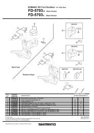
Installation of the Front Chainwheel and Front Derailleur<br />
Follow the procedure in the figure.<br />
1, 2 Use the special tool TL-FC32 to install the right adapter<br />
(counterclockwise thread) and the left adapter (clockwise<br />
thread).<br />
Tightening torque: 35 - 50 N·m {305 - 435 in. lbs.}<br />
3 Insert the right crank unit.<br />
4 Set section A of the left crank into the axle of the right crank<br />
unit where the groove is wide.<br />
5 Use the TL-FC16 to tighten the cap.<br />
Tightening torque: 0.7 - 1.5 N·m {6 - 13 in. lbs.}<br />
■ Spacer installation method<br />
(1) Check whether the width of the bottom bracket shell is<br />
68 mm or 73 mm.<br />
(2) Next, install the adapter while referring to the<br />
illustrations below.<br />
FD-<strong>M660</strong>-E FD-<strong>M660</strong> FD-M661 FD-M665/M667 FD-M665-E<br />
X<br />
X<br />
22T<br />
12T<br />
–<br />
66° - 69°<br />
X<br />
X<br />
22T<br />
12T<br />
S, M, L<br />
66° - 69°<br />
50 mm 50 mm<br />
44T 44T / 48T<br />
TL-FC16<br />
Push up<br />
X X<br />
X X<br />
22T 14T<br />
12T –<br />
S, M, L S, M, L<br />
66° - 69° 65° - 71°<br />
50 mm 50 mm<br />
44T 36T<br />
X = Available<br />
X<br />
X<br />
14T<br />
–<br />
–<br />
65° - 71°<br />
50 mm<br />
36T<br />
Triple (FD-<strong>M660</strong>-E/M600/M661)<br />
5<br />
6 Push in the stopper plate and check that the plate pin is<br />
securely in place, and then tighten the bolt of the left crank<br />
arm.<br />
Note : Each of the bolts should be evenly and equally<br />
tightened to 12 - 15 N·m {106 - 132 in. lbs.}.<br />
Plate pin<br />
Stopper plate<br />
FC-<strong>M660</strong><br />
Gear teeth should<br />
come within this range<br />
FC-<strong>M660</strong><br />
44-32-22T / 48-36-26T<br />
104 mm / 64 mm<br />
170 mm, 175 mm<br />
50 mm<br />
68, 73 mm<br />
BC1.37 (68, 73mm)<br />
4<br />
(A)<br />
6<br />
TL-FC32<br />
2<br />
Pro-Set gauge<br />
Pro-Set gauge<br />
Installation band diameters:<br />
S (28.6 mm), M (31.8 mm), L (34.9 mm)<br />
When using the S, M size, use an<br />
installation band with a diameter of 28.6<br />
mm, 31.8mm and install it to a L size<br />
adapter.<br />
Chainstay angle<br />
Wide groove area<br />
FC-M665<br />
Double (FD-M665/M667)<br />
36-22T<br />
104 mm / 64 mm<br />
170 mm, 175 mm<br />
50 mm<br />
68, 73 mm<br />
BC1.37 (68, 73mm)<br />
1<br />
Inner cover<br />
Note :<br />
Set the stopper plate in<br />
the right direction as<br />
shown in illustration.<br />
3<br />
Pro-Set alignment block<br />
■ Note<br />
When installing the components to carbon frame/handle bar<br />
surfaces, verify with the manufacturer of the carbon frame/parts for<br />
their recommendation on tightening torque in order to prevent over<br />
tightening that can cause damage to the carbon material and/or<br />
under tightening that can cause lack of fixing strength for the<br />
components.<br />
FC-<strong>M660</strong><br />
The level section of the chain guide outer<br />
plate should be directly above and<br />
parallel to the largest chainring. Secure<br />
using a 5 mm Allen key.<br />
FC-M665<br />
The inner surface of the bash guard<br />
should be at the flat part of the chain<br />
guide outer plate.<br />
Tightening torque :<br />
5 - 7 N·m {44 - 60 in. lbs.}<br />
Chain length<br />
Add 2 links (with the chain on both<br />
the largest sprocket and the largest<br />
chainring)<br />
Installation of the lever<br />
If not using the indicator, this shifting lever can be installed either<br />
on the inside or the outside of the brake lever.<br />
If adjusting the position, remove the indicator, and then be sure<br />
to secure it in the new position with the two fixing bolts.<br />
• Install the shifting lever in a position where it will not obstruct brake<br />
operation and gear shifting operation.<br />
• Do not use in a combination which causes brake operation to be<br />
obstructed.<br />
SIS Adjustment (Triple)<br />
Cutting the outer casing<br />
After cutting the outer casing, make the end<br />
round so that the inside of the hole has a<br />
uniform diameter.<br />
Chainwheel<br />
(largest chainring)<br />
Chain guide<br />
Largest sprocket Largest chainring<br />
Chain<br />
Be sure to follow the sequence described below.<br />
1. Low adjustment<br />
First remove the Pro-Set alignment block .<br />
Next, set so that the clearance between the chain guide inner<br />
plate and the chain is 0 - 0.5 mm.<br />
Chain position<br />
Largest<br />
sprocket<br />
Pro-Set alignment<br />
block<br />
Smallest<br />
chainring<br />
4 mm Allen key<br />
Outboard Inboard<br />
3 mm Allen key<br />
FD-M661<br />
Chain guide<br />
inner plate<br />
Chain<br />
2. Connecting and securing the inner cable<br />
Operate lever (B) two times or more, Lever (B)<br />
and check on the indicator that the<br />
lever is at the lowest position. Then<br />
remove the inner hole cover and<br />
connect the inner cable.<br />
Attach the same outer<br />
end cap to the cut end of<br />
the outer casing.<br />
A<br />
Inner hole cover<br />
Install the inner hole cover by turning it as<br />
shown in the illustration until it stops.<br />
Do not turn it any further than this, otherwise<br />
it may damage the screw thread.<br />
Tightening torque :<br />
0.3 - 0.5 N·m {3 - 4 in. lbs.}<br />
Use a handlebar grip with a<br />
maximum outer diameter of 36 mm.<br />
Outer end cap<br />
Tightening torque :<br />
5 N·m {44 in. lbs.}<br />
Tightening torque :<br />
2.5 N·m {22 in. lbs.}<br />
3 mm Allen key<br />
B<br />
Inner cable<br />
B A<br />
Low adjustment<br />
screw<br />
FD-<strong>M660</strong><br />
Inner hole cover<br />
• FD-<strong>M660</strong><br />
< Normal type ><br />
• FD-M661<br />
< Normal type ><br />
After taking up the initial slack in the cable, re-secure to the front<br />
derailleur as shown in the illustration.<br />
Normal type Top route type<br />
Chain position<br />
Smallest<br />
sprocket<br />
Chain position<br />
Largest<br />
sprocket<br />
Pull<br />
3. Top adjustment<br />
Set so that the clearance<br />
between the chain guide outer<br />
plate and the chain is 0 - 0.5<br />
mm.<br />
Largest<br />
chainring<br />
Intermediate<br />
chainring<br />
FD-<strong>M660</strong><br />
FD-M661<br />
4. Adjustment of the intermediate<br />
chainring<br />
When carrying out adjustment, set the<br />
chain to the largest sprocket, and at the<br />
front, set the chain to the intermediate<br />
chainring. Adjust using the outer casing<br />
adjustment barrel so that the clearance<br />
between the chain guide inner plate and<br />
the chain is 0 - 0.5 mm.<br />
If the chain falls to the crank<br />
side.<br />
If shifting is difficult from the<br />
intermediate chainring to the<br />
smallest chainring.<br />
If there is interference between<br />
the chain and the front derailleur<br />
inner plate at the largest<br />
chainring.<br />
If there is interference between<br />
the chain and the front derailleur<br />
outer plate at the largest<br />
chainring.<br />
If the intermediate chainring is<br />
skipped when shifting from the<br />
largest chainring.<br />
If the chain falls to the bottom<br />
bracket side.<br />
If the lever is stiff when shifting<br />
from the intermediate chainring<br />
to the largest chainring<br />
Pull<br />
Chain guide<br />
inner plate<br />
Chain<br />
B<br />
Top adjustment<br />
screw<br />
Chain guide<br />
outer plate<br />
Chain<br />
B<br />
A<br />
Outer casing adjustment barrel<br />
5. Troubleshooting chart<br />
After completion of steps 1 - 4, move the shifting lever to check the<br />
shifting. (This also applies if shifting becomes difficult during use.)<br />
If shifting is difficult from the<br />
intermediate chainring to the<br />
largest chainring.<br />
Note:<br />
Pass the cable<br />
through as shown<br />
in the illustration.<br />
If there is interference between<br />
the chain and front derailleur<br />
inner plate when the rear<br />
sprocket is shifted to the largest<br />
sprocket when the chainwheel is<br />
at the intermediate chainring<br />
position.<br />
Wire<br />
fixing bolt<br />
Note:<br />
Pass the cable<br />
through as shown<br />
in the illustration.<br />
Wire<br />
fixing bolt<br />
Tightening torque :<br />
5 - 7 N·m {44 - 60 in. lbs.}<br />
< Top route type ><br />
5 mm Allen key<br />
< Top route type ><br />
Tighten the top adjustment screw<br />
clockwise (about 1/4 turn).<br />
Loosen the top adjustment screw<br />
counterclockwise<br />
(about 1/8 turn).<br />
Loosen the low adjustment screw<br />
counterclockwise<br />
(about 1/4 turn).<br />
Tighten the top adjustment screw<br />
clockwise (about 1/8 turn).<br />
Loosen the top adjustment screw<br />
counterclockwise<br />
(about 1/8 turn).<br />
Loosen the outer casing<br />
adjustment barrel<br />
counterclockwise (1 or 2 turns).<br />
Tighten the outer casing<br />
adjustment barrel clockwise<br />
(1 or 2 turns).<br />
Tighten the low adjustment screw<br />
clockwise (about 1/2 turn).<br />
Loosen the top adjustment screw<br />
counterclockwise (about 1/4<br />
turn).<br />
■ Refer to the Service Instructions for the Rear Drive<br />
System for details on replacing and installing the<br />
indicator unit.<br />
A
SI-6PZRA-003-00<br />
General Safety Information<br />
WARNING<br />
• Check that the wheels are fastened securely before riding the bicycle. If the wheels are loose in any way, they may come off the<br />
bicycle and serious injury may result.<br />
• Use neutral detergent to clean the chain. Do not use alkali-based or acid based detergent such as rust cleaners as it may result<br />
in damage and/or failure of the chain.<br />
• Use the reinforced connecting pin only for connecting the narrow type of chain.<br />
• There are two different types of reinforced connecting pins available. Be sure to check the table below before selecting which<br />
pin to use.<br />
If connecting pins other than reinforced connecting<br />
pins are used, or if a reinforced connecting pin or tool<br />
which is not suitable for the type of chain is used,<br />
sufficient connection force may not be obtained, which<br />
could cause the chain to break or fall off.<br />
• If it is necessary to adjust the length of the chain due<br />
to a change in the number of sprocket teeth, make the<br />
cut at some other place than the place where the chain<br />
has been joined using a reinforced connecting pin or an end pin. The chain will be damaged if it<br />
is cut at a place where it has been joined with a reinforced connecting pin or an end pin.<br />
• Check that the tension of the chain is correct and that the chain is not damaged. If the tension<br />
is too weak or the chain is damaged, the chain should be replaced. If this is not done, the chain<br />
may break and cause serious injury.<br />
• Use a front chainwheel which is compatible with 9-speed chains in conjunction with Shimano<br />
CN-7701, CN-HG93 and CN-HG73 chains. If a chainwheel for an 8-speed chain or less is used, front chainwheel gear shifting<br />
problems may occur, or the chain pins might fall out, causing the chain to break.<br />
• Obtain and read the service instructions carefully prior to installing the parts. Loose, worn or damaged parts may cause the<br />
bicycle to fall over and serious injury may occur as a result. We strongly recommend only using genuine Shimano replacement<br />
parts.<br />
• Obtain and read the service instructions carefully prior to installing the parts. If adjustments are not carried out correctly, the<br />
chain may come off and this may cause you to fall off the bicycle which could result in serious injury.<br />
• Read these Technical Service Instructions carefully, and keep them in a safe place for later reference.<br />
Note<br />
• If gear shifting operations do not feel smooth, wash the derailleur and lubricate all moving parts.<br />
• If the amount of looseness in the links is so great that adjustment is not possible, you should replace the derailleur.<br />
• You should periodically clean the derailleur and lubricate all moving parts (mechanism and pulleys).<br />
• If gear shifting adjustment cannot be carried out, check the degree of parallelism at the rear end of the bicycle. Also check if the<br />
cable is lubricated and if the outer casing is too long or too short.<br />
• If you hear abnormal noise as a result of looseness in a pulley, you should replace the pulley.<br />
• If the wheel becomes stiff and difficult to turn, you should lubricate it with grease.<br />
• Do not apply any oil to the inside of the hub, otherwise the grease will come out.<br />
• You should periodically wash the sprockets in a neutral detergent and then lubricate them again. In addition, cleaning the chain<br />
with neutral detergent and lubricating it can be a effective way of extending the useful life of the sprockets and the chain.<br />
• If the chain keeps coming off the sprockets during use, replace the sprockets and the chain.<br />
• Use a frame with internal cable routing is strongly discouraged as it has tendencies to impair the SIS shifting function due to its<br />
high cable resistance.<br />
• Always be sure to use the sprocket set bearing the same group marks. Never use in combination with a sprocket bearing a<br />
different group mark.<br />
Group marks<br />
• Use an outer casing which still has some length to spare even when the handlebars are turned all the way<br />
to both sides. Furthermore, check that the shifting lever does not touch the bicycle frame when the<br />
handlebars are turned all the way.<br />
• A special grease is used for the gear shifting cable (SIS-SP41). Do not use DURA-ACE grease or other<br />
types of grease, otherwise they may cause deterioration in gear shifting performance.<br />
• Grease the inner cable and the inside of the outer casing before use to ensure that they slide properly.<br />
• For smooth operation, use the specified outer casing and the bottom bracket cable guide.<br />
• Operation of the levers related to gear shifting should be made only when the front chainwheel is turning.<br />
• If the brake fluid used in the oil disc brakes is of a type which tends to adhere to the plastic parts of the shifting lever, this may<br />
cause the plastic parts to crack or become discolored. Therefore, you should make sure that the brake fluid does not adhere to<br />
these plastic parts.<br />
The mineral oil which is used in SHIMANO disc brakes does not cause cracking or discoloration if it adheres to plastic parts, but<br />
such parts should be cleaned with alcohol beforehand to prevent foreign particles from adhering.<br />
• Do not disassemble the indicator and shifting lever unit, as this may damage them or cause mis-operation.<br />
• Parts are not guaranteed against natural wear or deterioration resulting from normal use.<br />
• For maximum performance we highly recommend Shimano lubricants and maintenance products<br />
• For any questions regarding methods of installation, adjustment, maintenance or operation, please contact a professional<br />
bicycle dealer.<br />
Chain<br />
9-speed super narrow<br />
chain such as<br />
CN-7701 / CN-HG93<br />
8- / 7- / 6-speed narrow<br />
chain such as<br />
CN-HG50 / CN-HG40<br />
Reinforced<br />
connecting pin<br />
Chain tool<br />
TL-CN32 / TL-CN27<br />
TL-CN32 / TL-CN27<br />
Technical Service Instructions SI-6PZRA-003<br />
Series <strong>SL</strong>X<br />
RAPIDFIRE (Shifting lever) <strong>SL</strong>-<strong>M660</strong><br />
Outer casing SIS-SP41<br />
Rear derailleur RD-M662<br />
Type SGS / GS<br />
Freehub FH-M665<br />
Gears 9<br />
Cassette sprocket<br />
Chain<br />
Bottom bracket guide<br />
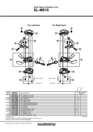
Rear Drive System<br />
In order to realize the best performance, we recommend that the following combination be used.<br />
6.5mm<br />
7.1mm<br />
CS-HG80<br />
CN-HG73<br />
SM-SP17<br />
One Holland, Irvine, California 92618, U.S.A. Phone: +1-949-951-5003 Industrieweg 24, 8071 CT Nunspeet, The Netherlands Phone: +31-341-272222 3-77 Oimatsu-cho, Sakai-ku, Sakai-shi, Osaka 590-8577, Japan<br />
* Service Instructions in further languages are available at : http://techdocs.shimano.com<br />
Please note: specifications are subject to change for improvement without notice. (English) © May 2009 by Shimano Inc. XBC SZK Printed in Japan.<br />
Silver<br />
Black<br />
Reinforced Connecting Pin<br />
End Pin Link Pin<br />
This service instruction explains how to use and maintain the Shimano bicycle parts which have been used on your new bicycle.<br />
For any questions regarding your bicycle or other matters which are not related to Shimano parts, please contact the place of<br />
purchase or the bicycle manufacturer.<br />
g<br />
a -18T<br />
SHIMANO HYPERGLI DE C<br />
-<br />
ag-15T<br />
ag -13T<br />
Specifications<br />
Rear Derailleur<br />
Model number<br />
Type<br />
Gears<br />
Total capacity<br />
Largest sprocket<br />
Smallest sprocket<br />
Front chainwheel tooth difference<br />
Cassette sprocket tooth combination<br />
Model number<br />
CS-HG80<br />
ba<br />
Group name<br />
ba<br />
ba<br />
ar<br />
au<br />
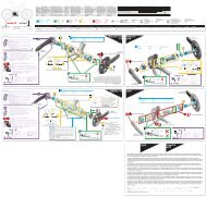
Installation of the sprockets<br />
32T<br />
28T<br />
34T<br />
24T<br />
30T<br />
26T<br />
ap as<br />
ap as<br />
ar<br />
ba<br />
ap ba<br />
ba<br />
aQ<br />
ap<br />
aQ<br />
ap<br />
ar ba<br />
21T<br />
18T<br />
Gears<br />
14T<br />
as<br />
16T<br />
ap as<br />
9<br />
9<br />
23T 20T<br />
17T<br />
aQ<br />
as<br />
ar<br />
12T<br />
ba<br />
9S<br />
11T aQ<br />
ba<br />
ar<br />
15T<br />
as<br />
au<br />
A AN<br />
J P<br />
Y<br />
H P<br />
13T<br />
ER G LI D<br />
11T<br />
E<br />
M 9 0<br />
as au<br />
CS- 6<br />
11T<br />
as au<br />
A AN<br />
J P<br />
Y<br />
H P<br />
ER G LI D<br />
11T<br />
E<br />
M 9 0<br />
CS- 6<br />
RD-M662<br />
SGS GS<br />
45T<br />
34T<br />
11T<br />
22T<br />
Tooth combination<br />
11, 12, 14, 16, 18, 21, 24, 28, 32T<br />
11, 13, 15, 17, 20, 23, 26, 30, 34T<br />
9<br />
Freehub<br />
Model number<br />
Gears<br />
No. of spoke holes<br />
35T<br />
34T<br />
11T<br />
22T<br />
FH-M665<br />
These Service Instructions describe the operation method when using the RAPIDFIRE <strong>SL</strong>-<strong>M660</strong> in combination with the RD-M662 top<br />
normal-type rear derailleur. If using in combination with a reverse spring-type derailleur, the operations and indicator displays will be<br />
reversed.<br />
Gear shifting operation<br />
This release lever is equipped with a 2-way release mechanism which allows release operations to be carried out by either pushing or pulling<br />
the lever.<br />
Both lever (A) and lever (B) always return to the initial position when they are released after shifting. When operating one of the levers,<br />
always be sure to turn the crank arm at the same time.<br />
To shift from a small sprocket to a larger sprocket<br />
(Lever A)<br />
To shift one step only, press lever (A) to the (1) position. To shift two<br />
steps at one time, press to the (2) position.<br />
CS-HG80 (ar)<br />
CS-HG80 (au)<br />
Lever (A) initial position<br />
Sprocket spacer<br />
Lock ring<br />
Lock ring spacer<br />
Lock ring spacer<br />
Lock ring<br />
For each sprocket, the surface that has the group mark should face outward and be<br />
positioned so that the wider part of each sprocket and the A part (where the groove width<br />
is wide) of the freewheel body are aligned.<br />
Chain length on bicycles<br />
with rear suspension<br />
The length of A will vary depending on the movement of the rear<br />
suspension. Because of this, an excessive load may be placed on<br />
the drive system if the chain length is too short. Set the length of<br />
the chain by adding two links to the chain when the rear suspension<br />
is at a position where dimension "A" is longest and the chain is on<br />
the largest sprocket and the largest chainring. If the amount of<br />
movement of the rear suspension is large, the slack in the chain<br />
may not be taken up properly when the chain is on the smallest<br />
chainring and smallest sprocket.<br />
A<br />
A'<br />
Largest<br />
sprocket<br />
Chain<br />
Largest<br />
chainring<br />
Add 2 links (with the chain on<br />
both the largest sprocket and<br />
the largest chainring)<br />
9<br />
36 / 32<br />
To shift from a large sprocket to a smaller sprocket<br />
(Lever B)<br />
Press lever (B) once to shift one step from a larger to a smaller<br />
sprocket.<br />
Installation of the lever<br />
Use a handlebar grip with a maximum<br />
outer diameter of 36 mm.<br />
• For installation of the sprockets, use<br />
the special tool (TL-LR15) to tighten<br />
the lock ring.<br />
Tightening torque:<br />
30 - 50 N·m {261 - 434 in. lbs.}<br />
• To replace the sprockets, use the<br />
special tool (TL-LR15) and TL-SR21<br />
to remove the lock ring.<br />
TL-LR15<br />
Disassembly<br />
Tightening torque :<br />
5 N·m {44 in. lbs.} 4 mm Allen key<br />
Lever (B)<br />
2-way release<br />
Lock ring<br />
Tool<br />
(TL-SR21)<br />
If not using the indicator, this shifting lever can be installed either<br />
on the inside or the outside of the brake lever.<br />
If adjusting the position, remove the indicator, and then be sure<br />
to secure it in the new position with the two fixing bolts.<br />
Inboard Outboard<br />
3 mm Allen key<br />
A<br />
The groove is wide at<br />
one place only.<br />
3 mm Allen key<br />
• Install the shifting lever in a position where it will not obstruct brake<br />
operation and gear shifting operation.<br />
• Do not use in a combination which causes brake operation to be<br />
obstructed.<br />
• When installing the components to carbon frame/handle bar<br />
surfaces, verify with the manufacturer of the carbon frame/parts for<br />
their recommendation on tightening torque in order to prevent over<br />
tightening that can cause damage to the carbon material and/or<br />
under tightening that can cause lack of fixing strength for the<br />
components.<br />
ac-14T<br />
Wide part<br />
Tightening torque :<br />
2.5 N·m {22 in. lbs.}<br />
Refer to the RD-M662 (Rear Derailleur) Service Instructions for<br />
details on installing the rear derailleur and SIS adjustment.<br />
Connection and securing of the inner<br />
cable<br />
Operate lever (B) eight times or<br />
more, and check on the indicator<br />
that the lever is at the highest<br />
position. Then remove the inner hole<br />
cover and connect the inner cable.<br />
Inner cable<br />
Install the inner hole cover by turning it as shown in the<br />
illustration until it stops.<br />
Do not turn it any further than this,<br />
otherwise it may damage the screw<br />
thread.<br />
Inner hole cover<br />
Replacing and installing the indicator<br />
Lever (B)<br />
Inner hole cover<br />
Cutting the outer casing<br />
When cutting the outer casing, cut the<br />
opposite end to the end with the marking.<br />
After cutting the outer casing, make the<br />
end round so that the inside of the hole has a uniform diameter.<br />
Attach the same outer<br />
end cap to the cut end<br />
of the outer casing.<br />
The sealed cap with<br />
tongue and the rubber<br />
shield should be<br />
installed to the outer<br />
casing stopper of the<br />
frame.<br />
Outer end cap<br />
Be careful not to bend<br />
Sealed cap with tongue<br />
Rubber shield<br />
Rubber shield<br />
* If the rear derailleur moves to a large degree, such as in<br />
bicycles with rear suspension, it is recommended that you<br />
replace the cap with the<br />
accessory aluminum cap.<br />
Derailleur side<br />
The end of the outer casing<br />
which has the aluminum cap<br />
should be at the derailleur side.<br />
Aluminum cap<br />
Replacement of the freewheel body<br />
After removing the hub<br />
axle, remove the freewheel<br />
body fixing bolt (inside<br />
the freewheel body),<br />
and then replace the<br />
freewheel body.<br />
Install the rubber seal as<br />
the last item after replacing<br />
the freewheel body, and make<br />
sure that it does not get<br />
clamped by the waterproof cap.<br />
Disassembly and reassembly should only be carried out when<br />
removing or replacing the indicator. For the front, the direction of<br />
rotation when removing and installing is opposite to the position of<br />
the needle.<br />
[Removal]<br />
1. Remove the two indicator fixing screws which are securing the<br />
indicator.<br />
2. Lift up the lens as shown in the illustration, and then disengage<br />
the hooked part and remove the indicator unit.<br />
Hooked part<br />
Rubber seal<br />
Indicator fixing screws<br />
Lens<br />
Freewheel body Freewheel body fixing bolt<br />
Indicator unit<br />
10 mm Allen key<br />
(TL-WR37)<br />
Disassembly<br />
Note: Do not attempt to<br />
disassemble the<br />
freewheel body,<br />
because it may result<br />
in a malfunction.<br />
Assembly<br />
Tightening torque :<br />
35 - 50 N·m {305 - 434 in. lbs.}<br />
[Installation]<br />
3. Operate lever B eight times or<br />
more to set the lever to the top<br />
Pin<br />
position.<br />
4. Check that the indicator needle is<br />
pointing to the left, and align the<br />
pin at the bottom of the indicator<br />
and the boss on the indicator with<br />
the o marks on the shifting lever<br />
unit. Then insert the indicator into<br />
the shifting lever unit as shown in<br />
the illustration, starting with the<br />
boss and then followed by the pin<br />
in the reverse order to removal.<br />
5. Tighten the two indicator fixing screws.<br />
6. Check the operation of the indicator. If it does not operate<br />
correctly, reinstall it while paying particular attention to steps 3<br />
and 4.<br />
<br />
1. Remove the indicator bracket protective cover which is attached<br />
to the indicator, starting from the shorter tab as shown in the<br />
illustration.<br />
2. First insert the tab of the indicator bracket protective cover into<br />
the slot which does not have a o mark, and then set it onto the<br />
shifting lever unit and secure it with the indicator fixing screw.<br />
Indicator unit<br />
Indicator bracket<br />
protective cover<br />
Shorter tab<br />
Tightening torque :<br />
0.2 N·m {1 in. lbs.}<br />
1mm<br />
Tightening torque :<br />
0.2 N·m {1 in. lbs.}<br />
Indicator bracket<br />
protective cover<br />
Shifting lever unit<br />
NOTE:<br />
Do not push the brake lever against the indicator cover,<br />
otherwise it may cause problems with the operation of the<br />
needle.