Design of Pig Casting Machine - IJET
Design of Pig Casting Machine - IJET
Design of Pig Casting Machine - IJET

You also want an ePaper? Increase the reach of your titles
YUMPU automatically turns print PDFs into web optimized ePapers that Google loves.
IACSIT International Journal <strong>of</strong> Engineering and Technology, Vol.2, No.6, December 2010<br />
ISSN: 1793-8236<br />
<strong>Design</strong> <strong>of</strong> <strong>Pig</strong> <strong>Casting</strong> <strong>Machine</strong><br />
S.N. Waghmare, C.N. Sakhale, M.S.Giripunje and V.M. Sonde<br />
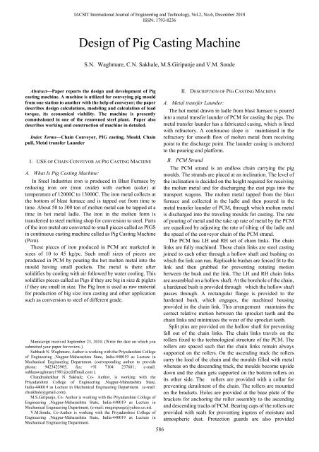
Abstract—Paper reports the design and development <strong>of</strong> <strong>Pig</strong><br />
casting machine. A machine is utilized for conveying pig mould<br />
from one station to another with the help <strong>of</strong> conveyor; the paper<br />
describes design calculations, modeling and calculation <strong>of</strong> load<br />
torque, its economical viability. The machine is presently<br />
commissioned in one <strong>of</strong> the renowned steel plant. Paper also<br />
describes working and construction <strong>of</strong> machine in detailed.<br />
Index Terms—Chain Conveyor, PIG casting, Mould, Chain<br />
pull, Metal transfer Launder<br />
I. USE OF CHAIN CONVEYOR AS PIG CASTING MACHINE<br />
A. What Is <strong>Pig</strong> <strong>Casting</strong> <strong>Machine</strong>:<br />
In Steel Industries iron is produced in Blast Furnace by<br />
reducing iron ore (iron oxide) with carbon (coke) at<br />
temperature <strong>of</strong> 12000C to 13000C. The iron metal collects at<br />
the bottom <strong>of</strong> blast furnace and is tapped out from time to<br />
time. About 50 to 300 ton <strong>of</strong> molten metal can be tapped at a<br />
time in hot metal ladle. The iron in the molten form is<br />
transferred to steel melting shop for conversion to steel. Parts<br />
<strong>of</strong> the iron metal are converted to small pieces called as PIGS<br />
in continuous casting machine called as <strong>Pig</strong> <strong>Casting</strong> <strong>Machine</strong><br />
(Pcm).<br />
These pieces <strong>of</strong> iron produced in PCM are marketed in<br />
sizes <strong>of</strong> 10 to 45 kg/pc. Such small sizes <strong>of</strong> pieces are<br />
produced in PCM by pouring the hot molten metal into the<br />
mould having small pockets. The metal is there after<br />
solidifies by cooling with air followed by water cooling. This<br />
solidifies pieces called as <strong>Pig</strong>s if they are big in size & piglets<br />
if they are small in size. The <strong>Pig</strong> Iron is used as raw material<br />
for production <strong>of</strong> big size iron casting and other application<br />
such as conversion to steel <strong>of</strong> different grade.<br />
Manuscript received September 23, 2010. (Write the date on which you<br />
submitted your paper for review.)<br />
Subhash N. Waghmare, Author is working with the Priyadarshini College<br />
<strong>of</strong> Engineering ,Nagpur-Maharashtra State, India-440019 as Lecture in<br />
Mechanical Engineering Department. (corresponding author to provide<br />
phone: 9423423905; fax: +91 7104 237681; e-mail:<br />
subhaswaghmare1981@rediffmail.com ).<br />
Chandrashekhar N Sakhale, Co- Author, is working with the<br />
Priyadarshini College <strong>of</strong> Engineering ,Nagpur-Maharashtra State,<br />
India-440019 as Lecture in Mechanical Engineering Department. (e-mail:<br />
chsakhale@gmail.com).<br />
M.S.Giripunje, Co- Author is working with the Priyadarshini College <strong>of</strong><br />
Engineering ,Nagpur-Maharashtra State, India-440019 as Lecture in<br />
Mechanical Engineering Department. (e-mail: mngiripunje@yahoo.co.in).<br />
V.M.Sonde, Co-Author is working with the Priyadarshini College <strong>of</strong><br />
Engineering ,Nagpur-Maharashtra State, India-440019 as Lecture in<br />
Mechanical Engineering Department.<br />
586<br />
II. DESCRIPTION OF PIG CASTING MACHINE<br />
A. Metal transfer Launder:<br />
The hot metal drawn in ladle from blast furnace is poured<br />
into a metal transfer launder <strong>of</strong> PCM for casting the pigs. The<br />
metal transfer launder has a fabricated casing, which is lined<br />
with refractory. A continuous slope is maintained in the<br />
refractory for smooth flow <strong>of</strong> molten metal from receiving<br />
point to the discharge point. The launder casing is anchored<br />
to the pouring end platform.<br />
B. PCM Strand<br />
The PCM strand is an endless chain carrying the pig<br />
moulds. The strands are placed at an inclination. The level <strong>of</strong><br />
the inclination is decided on the height required for receiving<br />
the molten metal and for discharging the cast pigs into the<br />
transport wagons. The molten metal tapped from the blast<br />
furnace and collected in the ladle and then poured in the<br />
metal transfer launder <strong>of</strong> PCM, through which molten metal<br />
is discharged into the traveling moulds for casting. The rate<br />
<strong>of</strong> pouring <strong>of</strong> metal and the take up rate <strong>of</strong> metal by the PCM<br />
are equalized by adjusting the rate <strong>of</strong> tilting <strong>of</strong> the ladle and<br />
the speed <strong>of</strong> the conveyor chain <strong>of</strong> the PCM strand.<br />
The PCM has LH and RH set <strong>of</strong> chain links. The chain<br />
links are fully machined. These chain links are steel casting<br />
joined to each other through a hollow shaft and bushing on<br />
which the link can run. Replicable bushes are forced fit to the<br />
link and then grubbed for preventing rotating motion<br />
between the bush and the link. The LH and RH chain links<br />
are assembled on a hollow shaft. At the borehole <strong>of</strong> the chain,<br />
a hardened bush is provided through which the hollow shaft<br />
passes through. A rectangular flange is provided to the<br />
hardened bush, which engages, the machined housing<br />
provided in the chain link. This arrangement maintains the<br />
correct relative motion between the sprocket teeth and the<br />
chain links and minimizes the wear <strong>of</strong> the sprocket teeth.<br />
Split pins are provided on the hollow shaft for preventing<br />
fall out <strong>of</strong> the chain links. The chain links travels on the<br />
rollers fixed to the technological structure <strong>of</strong> the PCM. The<br />
rollers are spaced such that the chain links remain always<br />
supported on the rollers. On the ascending track the rollers<br />
carry the load <strong>of</strong> the chain and the moulds filled with metal<br />
whereas on the descending track, the moulds become upside<br />
down and the chain gets supported on the bottom rollers on<br />
its other side. The rollers are provided with a collar for<br />
preventing derailment <strong>of</strong> the chain. The rollers are mounted<br />
on the brackets. Holes are provided at the base plate <strong>of</strong> the<br />
brackets for anchoring the roller assembly to the ascending<br />
and descending tracks <strong>of</strong> PCM. Bearing caps <strong>of</strong> the rollers are<br />
provided with seals for preventing ingress <strong>of</strong> moisture and<br />
atmospheric dust. Protection guards are also provided
IACSIT International Journal <strong>of</strong> Engineering and Technology, Vol.2, No.6, December 2010<br />
ISSN: 1793-8236<br />
beyond the bearing caps, which act as a secondary protecting<br />
to the system. Moulds are anchored to the chain at LH and<br />
RH links. The chain duly fitted with moulds forms the train.<br />
The chain links pass through the sprocket assembly at the<br />
discharge end and at pouring end. Motor gear unit drives the<br />
sprocket assembly at discharge end whereas the sprocket<br />
assembly at pouring end is free to rotate on its bearings. The<br />
PCM drive is coupled to the drive sprocket assembly by a<br />
geared coupling. The sprocket assembly at the pouring end is<br />
made to float to render compensation for expansion <strong>of</strong> chain<br />
links and for overcoming jams due to external reasons. A<br />
self-regulating tensioning device is provided at the individual<br />
sprocket assembly at the pouring end. The tensioning device<br />
consists <strong>of</strong> the following:<br />
• A fabricated base frame fitted with slide rail.<br />
• Bearing housing with guide seat matching with the<br />
slide rail for the base frame and clevis for connecting<br />
the tension rod through pins.<br />
• Tension rod having one end to connect to the bearing<br />
housing through pin and the other end threaded for<br />
adjusting the spring tension.<br />
• Compression springs.<br />
• Nut to suit the tension rod threading.<br />
The drive consists <strong>of</strong> the following:<br />
• AC sq. cage induction motor<br />
• A pin and bush coupling between motor and gear box<br />
• A helical gear box for speed reduction.<br />
• A geared coupling between the gear box out put shaft<br />
and the shaft <strong>of</strong> the drive sprocket assembly.<br />
A spillage chute is provided below the ascending track <strong>of</strong><br />
the strand at the location where metal is discharged from the<br />
metal transfer launder to the pig mould. The metal spilled at<br />
this location due to mismatch <strong>of</strong> rate <strong>of</strong> flow <strong>of</strong> metal and take<br />
up rate <strong>of</strong> metal by PCM, falls on the spillage chute.<br />
A pig-knocking device is provided at the discharge end<br />
sprocket assembly for quick discharge <strong>of</strong> the pigs from the<br />
mould. The pig-knocking device has a cam & follower<br />
mechanism for free fall <strong>of</strong> the knocker on the cast pig. The<br />
pig-knocking device mainly consists <strong>of</strong> the following:<br />
A cam disc fitted to the drive shaft <strong>of</strong> discharge end sprocket<br />
assembly. The cam pr<strong>of</strong>ile is matched to the sprocket teeth<br />
for accurate positioning <strong>of</strong> the knocker and for cent percent<br />
repeatability <strong>of</strong> the striking points.<br />
The cam actuates a lever mechanism.<br />
A roller moving on the shaft is provided at the end <strong>of</strong> the<br />
lever coming in contact with the cam. The other end <strong>of</strong> the<br />
cam is connected to the shaft <strong>of</strong> the knocking device.<br />
A Knocker arm with one end fitted to the shaft <strong>of</strong> pig<br />
knocking device and the other end having a knocker disc.<br />
Springs are provided on the knocker arm for absorbing the<br />
shock <strong>of</strong> the impact <strong>of</strong> the knocker above the tolerance limit.<br />
A <strong>Pig</strong> impact device consisting <strong>of</strong> a chain suspended to the<br />
technological structure is placed in front <strong>of</strong> the discharge end<br />
sprocket assembly. The purpose <strong>of</strong> the impact device is to<br />
absorb the impact <strong>of</strong> the pigs falling from the moulds at the<br />
discharge end. The pigs ejected/dislodged at discharge end<br />
loose the kinetic energy to the impact chain and fall on to the<br />
discharge chute.<br />
A discharge chute is placed below the discharge end<br />
sprocket for transferring the pigs to the product collection<br />
587<br />
wagons. A sand bag is provided at the pig-receiving end <strong>of</strong><br />
the discharge chute for absorbing the impact <strong>of</strong> the falling<br />
pigs. The angle <strong>of</strong> the discharge chute is selected to around<br />
450 to the vertical to enable easy transportation/sliding <strong>of</strong> the<br />
pigs. The bed <strong>of</strong> discharge chute is made <strong>of</strong> rail section,<br />
which gives long life and <strong>of</strong>fers minimum frictional force to<br />
the sliding pigs. The discharge chute is anchored to the<br />
technological structure <strong>of</strong> the PCM strand.<br />
A grizzly is placed below the return track <strong>of</strong> PCM strand<br />
for preventing fall <strong>of</strong> stickers on to the ground. The first<br />
termination point is before the lime splashing unit and the<br />
second at 1 meter above the ground level near the tail end. A<br />
chute is provided at the first termination point for collection<br />
<strong>of</strong> stickers at the ground level. The grizzly is anchored to the<br />
technological structure <strong>of</strong> PCM and an adequate clearance is<br />
provided between grizzly and traveling moulds such that<br />
stickers cannot get entrenched between them.<br />
A water trough is provided below the pig moulds at the<br />
ascending track for collection <strong>of</strong> surplus pig cooling water.<br />
The trough is connected to the return water pipeline which<br />
discharges the water to the return water trench running<br />
underground and on to the circulating water tank.<br />
C. Mould<br />
Metallic moulds are provided in PCM for casting pig iron.<br />
The mould has cavities for dividing the castings into 4 parts<br />
called piglets. The mould is designed with varying section<br />
thickness to maintain optimum heat transfer during the<br />
casting campaign. 2no. Support brackets are provided in a<br />
mould at opposite ends for anchoring the mould to the LH<br />
and RH chain <strong>of</strong> PCM. The support brackets are kept tilted to<br />
match the inclination <strong>of</strong> PCM strand so that the mould<br />
surface remains horizontal.<br />
The moulds anchored to the PCM chain forms the Train.<br />
For preventing spillage <strong>of</strong> metal during pouring <strong>of</strong> metal in<br />
moulds, the moulds are required to be interlocked with each<br />
other. The moulds are thus designed with twin interlocks as<br />
described below. When the metal is poured in the moulds, it<br />
can get spilled out between the front and rear matching<br />
surfaces <strong>of</strong> the pair <strong>of</strong> moulds. For preventing such spillage,<br />
the rear side <strong>of</strong> the mould is made in the form <strong>of</strong> a prism with<br />
a reverse tapered bottom surface. The front side <strong>of</strong> the mould<br />
is made with a rising nose. The front side <strong>of</strong> the hide mould<br />
engages the reverse tapered bottom surface with the leading<br />
mould making a perfect interlock. When the moulds are<br />
being filled up, the molten metal can leak from either side <strong>of</strong><br />
moulds, where the anchor brackets are provided. For<br />
preventing this leakage ribs, are provided in the moulds and<br />
curvatures on either side. The ribs <strong>of</strong> the preceding and<br />
succeeding moulds thus interlock with each other. Overflow<br />
notches are provided at the rear side <strong>of</strong> the mould. These<br />
notches limit the filling level <strong>of</strong> the mould the excess metal<br />
cascades to the downstream mould.<br />
The moulds are consumable spares <strong>of</strong> PCM. The life <strong>of</strong><br />
the mould depends upon the consistency and uniform<br />
filling <strong>of</strong> mould during casting campaign. In a casting<br />
campaign if all the hollow/pockets/cavities <strong>of</strong> the mould are<br />
not filled with the molten metal and the moulds with hallow<br />
pockets/cavities travel upwards, water gets filled up in the<br />
empty hollow/pockets/cavities at the water-cooling stage <strong>of</strong>
IACSIT International Journal <strong>of</strong> Engineering and Technology, Vol.2, No.6, December 2010<br />
ISSN: 1793-8236<br />
the stand, which causes thermal shocks and might result in<br />
the cracking <strong>of</strong> the moulds.<br />
D. Lime Milk Preparation and Splashing System:<br />
For preventing sticking <strong>of</strong> metal to the moulds, the<br />
moulds are coated with lime powder. Lime coating is done<br />
by spraying lime milk on the interior <strong>of</strong> the mould during<br />
their return passage. Lime powder is slaked before it is<br />
discharged into the lime milk preparation tank. The slaking <strong>of</strong><br />
lime is done in a classifier. The purpose <strong>of</strong> providing a<br />
classifier is to remove the grit continuously from the<br />
lime powder and to prepare the slaked lime for its transfer<br />
to the lime milk preparation unit. The lime milk preparation<br />
unit is a steel tank fitted with an impeller, driven by a motor<br />
gearbox unit. Continuous mechanical agitation makes a<br />
uniform lime milk suspension, which is pumped to the lime<br />
milk splasher unit. A port is also provided in this tank for<br />
receiving the return lime milk from the splasher unit.<br />
Slurry pumps are provided for transferring the lime milk<br />
from the lime milk preparation tank to the splashing tank.<br />
The capacity <strong>of</strong> the slurry pump is selected such that about 3<br />
times the volume <strong>of</strong> slurry required for coating the mould can<br />
be circulated. The excess quantity is returned to the lime milk<br />
preparation unit. Continuous circulation <strong>of</strong> lime milk<br />
between the lime milk preparation unit and the splashing unit,<br />
helps in getting a uniform lime milk suspension at the lime<br />
milk preparation unit as well as at the lime splashing unit<br />
and also avoids sedimentation at any location.<br />
The lime milk-splashing unit works on the principle <strong>of</strong><br />
scooping <strong>of</strong> lime milk, by continuous rotation <strong>of</strong> a paddle<br />
impeller partially submerged in the lime milk. For this<br />
purpose, two discs fitted on a shaft are housed in the<br />
fabricated body <strong>of</strong> the lime-splashing unit. At the periphery<br />
<strong>of</strong> the disc, are provided the scoops. The speed <strong>of</strong> the disc is<br />
adjusted such that adequate splashing velocities are<br />
achieved for coating <strong>of</strong> time on the cavities <strong>of</strong> the moulds.<br />
The location <strong>of</strong> the splashing unit is selected such that the<br />
return mould remains at adequate Temp. for immediate<br />
sticking <strong>of</strong> the lime to it and that the coated mould does not<br />
hold any water by the time the mould reaches the pouring end.<br />
Gland seals are provided at the exit points <strong>of</strong> the splasher<br />
body to prevent leakage <strong>of</strong> lime milk at these locations.<br />
The paddle shaft is supported on antifriction bearings and is<br />
coupled to a motor gearbox unit through a bush and pin type<br />
coupling. For the purpose <strong>of</strong> cleaning and maintenance a<br />
manhole is provided at the lower end <strong>of</strong> the splasher tank.<br />
Ports are provided in the splasher body for entry <strong>of</strong> lime milk<br />
and for outflow <strong>of</strong> the lime milk into the return line <strong>of</strong> the<br />
lime milk preparation unit. Interconnecting pipes and pipe<br />
fittings are provided in the lime milk preparation unit and<br />
splasher unit for making ring mains. Grating is provided at<br />
the topside <strong>of</strong> the splasher unit to prevent falling <strong>of</strong> sticker in<br />
the tank.<br />
E. Water Cooling System<br />
In the PCM, solidification <strong>of</strong> molten metal is achieved in<br />
two stages, first stage being natural air-cooling and the<br />
second stage being direct water quenching. The duration <strong>of</strong><br />
air-cooling is selected such that the top surface <strong>of</strong> the cast<br />
metal reaches a plastic state so that the water spray for<br />
quenching can commence without any explosion. The<br />
efficiency <strong>of</strong> the water-cooling system is a vital factor, which<br />
governs the temperature <strong>of</strong> the pigs discharged from PCM.<br />
The conventional types <strong>of</strong> nozzles used in spraying <strong>of</strong> water<br />
on the pigs, has demerit <strong>of</strong> choking <strong>of</strong> nozzles because <strong>of</strong><br />
unavoidable dust/carbon/lime particles getting mixed with<br />
the cooling water. The unique water spraying system<br />
designed & supplied by us for the various PCM overcomes<br />
the problems faced in conventional spraying systems. In our<br />
system water spraying is done through the flute holes<br />
provided on the top side <strong>of</strong> the water runner. A specially<br />
designed rotor is provided for adjusting the water flow which<br />
has self cleaning feature in built in it. Two/three circuits <strong>of</strong><br />
water spray are provided for avoiding pressure drop in<br />
cooling water pipelines. Water pipelines are suspended from<br />
the technological structure <strong>of</strong> PCM. Large sized nozzles for<br />
flooding <strong>of</strong> spillage chute are provided. Large size spray<br />
nozzles are also provided at the discharge end for cooling <strong>of</strong><br />
the discharged pigs (at the wagons). Regular pipeline<br />
connections are provided at the lime milk preparation unit for<br />
preparing lime milk. Water distributor is provided near the<br />
pouring end platform. The inlet <strong>of</strong> the distributor receives<br />
water from the circulating pump <strong>of</strong> PCM installed at the<br />
pump house located near/above the underground return water<br />
tank. The water distributor has two main outlets, first for<br />
water-cooling <strong>of</strong> mould/pigs and second for wagon spraying.<br />
A direct water connection from BF central water supply is<br />
recommended for the lime milk preparation unit and for the<br />
maintenance water taps points.<br />
F. Technological Structure <strong>of</strong> the PCM<br />
The PCM is supported on a technological structure. For<br />
convenience <strong>of</strong> operation and maintenance, following<br />
technological platforms, walkways, ladders/staircases and<br />
material handling facilities are provided.<br />
Pouring end platform with railing. It is recommended to<br />
have refractory flooring at the platform as the hot metal may<br />
spill over the place.<br />
Discharge end platform with railing. The discharge end<br />
sprocket assembly, strand drive, pig impactor,<br />
wagon-spraying unit and discharge chute are mounted on the<br />
platform.<br />
Walkways with railings along the sides <strong>of</strong> PCM strands<br />
(with common middle walkway for twin strand).<br />
Staircases/ladders with railing for reaching the walkways<br />
at lower lever and discharge end platform.<br />
Covered shed above the discharge end platform.<br />
III. ANALATICAL CALCULATION FOR MAXIMUM CHAIN<br />
PULL<br />
To enable the most suitable chain to be selected for a<br />
particular application it is necessary to know full application<br />
details such as the following:<br />
• Type <strong>of</strong> conveyor.<br />
• Conveyor centre distance and inclination from the<br />
horizontal.<br />
• Type <strong>of</strong> chain attachment, spacing and method <strong>of</strong><br />
fixing to the chain.<br />
• Number <strong>of</strong> chains and chain speed.<br />
588
IACSIT International Journal <strong>of</strong> Engineering and Technology, Vol.2, No.6, December 2010<br />
ISSN: 1793-8236<br />
• Details <strong>of</strong> conveying attachments, e.g. weight <strong>of</strong> slats,<br />
buckets, etc.<br />
• Description <strong>of</strong> material carried, i.e. weight, size and<br />
quantity.<br />
• Method <strong>of</strong> feed and rate <strong>of</strong> delivery.<br />
The preferred method <strong>of</strong> calculating the tension in a<br />
conveyor chain is to consider each section <strong>of</strong> the conveyor<br />
that has a different operating condition. This is particularly<br />
necessary where changes in direction occur or where the load<br />
is not constant over the whole <strong>of</strong> the conveyor. For uniformly<br />
loaded conveyors there is a progressive increase in chain<br />
tension from theoretically zero at A to a maximum at D. This<br />
is illustrated graphically in Fig. 14 where the vertical<br />
distances represent the chain tension occurring at particular<br />
points in the circuit, the summation <strong>of</strong> which gives the total<br />
tension in the chain. Thus, in Fig. 4.1 the maximum pull at D<br />
comprises the sum <strong>of</strong>:<br />
Fig 3.1: Maximum Chain Pull Diagram<br />
(a) Pull due to chain and moving parts on the unloaded<br />
side.<br />
(b) Extra pull required to turn the idler wheels and shaft.<br />
(c) Pull due to chain and moving parts on the loaded side.<br />
(d) Pull due to the load being moved.<br />
If it is imagined that the chains are ‘cut’ at position X then<br />
there will be a lower load pull or tension at this position than<br />
at Y. This fact is significant in the placing <strong>of</strong> caterpillar drives<br />
in complex circuits and also in assessing tension loadings for<br />
automatic take-up units. This principle has been used to<br />
arrive at the easy reference layouts and formulae to which<br />
most conveyor and elevator applications should<br />
conform.<br />
A. Data Collected<br />
S.N. Title Calculation<br />
1 Hot metal ladle carrying capacity 40 Ton<br />
2 Rate <strong>of</strong> pouring 01 ton /min<br />
3<br />
Weight <strong>of</strong> one <strong>Pig</strong>let for easy charging in<br />
foundries<br />
11.5 kg<br />
4 Total kg <strong>of</strong> piglet in one mould 04<br />
5 Total weight in one mould<br />
11.5 x 4= 45<br />
kg<br />
6 Size <strong>of</strong> pocket in mould<br />
7<br />
8<br />
9<br />
10<br />
11<br />
12<br />
Density <strong>of</strong> molten metal (at liquid state)<br />
Keeping the length <strong>of</strong> one pocket<br />
Total volume required for 11.5 kg <strong>of</strong> pig let<br />
Since we have considered length <strong>of</strong> pocket<br />
250mm<br />
So cross sectional area will be<br />
Considering the heat transfer rate for<br />
cooling <strong>of</strong> molten metal in pig mould, after<br />
pouring the temperature <strong>of</strong> pig mould<br />
should come down below 6000C Size <strong>of</strong><br />
pig mould was decided as<br />
Width <strong>of</strong> mould kept as 310 (305 pitch &<br />
5mm for over lapping)<br />
6.8 ton /cum<br />
250mm<br />
11.5/6.8=1.6<br />
91 lit.<br />
1691/25=65<br />
sqcm<br />
Cross<br />
sectional<br />
area will be<br />
<strong>of</strong> triangular<br />
shape <strong>of</strong> 10 x<br />
13cm<br />
1050 x 310 x<br />
250<br />
13 Molten metal pouring per mould<br />
45 kg at<br />
13000C<br />
14 To carry 1Ton <strong>of</strong> molten metal in one min 1000/45=22.<br />
589<br />
total no <strong>of</strong> pig mould required<br />
22 No <strong>of</strong> pig<br />
mould<br />
15 Since pitch <strong>of</strong> pig mould 305 mm<br />
17<br />
The speed <strong>of</strong> the pig casting machine<br />
comes out to be<br />
22.22 x 305<br />
= 6777.1 mm<br />
i.e. = 7<br />
m/min<br />
18 U = Coefficient <strong>of</strong> friction for bearing, 0.0064<br />
19<br />
f = Coeff. <strong>of</strong> friction for the track<br />
Resistance,<br />
0.1<br />
20 T = Torque, Nm<br />
21 Pitch Diameter <strong>of</strong> sprocket 1000 mm<br />
22 Length <strong>of</strong> <strong>Machine</strong> c/c 42 mtr<br />
B. Chain Pull Calculation<br />
The system to be chain sliding & Material Carried<br />
• From Renold <strong>Design</strong>er Guide book we consider BS<br />
series Index 400.<br />
• Total Load on Chain Conveyor from take up point =<br />
45 x 37 mtr = 1665 kg<br />
• Estimated mass <strong>of</strong> chain & mould = 30 kg +128 kg =<br />
158 kg<br />
• Load in one mtr distance =1000/305 = 3.2786<br />
• Weight per mtr = 3.2786 x 158 = 518 kg<br />
• Weight <strong>of</strong> APRON in empty condition(Wa) (weight<br />
<strong>of</strong> chain link & pig mould) = 518 x 42 = 21756 kg<br />
• 21756 x 9.81 = 213426.36 N (213.42 KN)<br />
• Weight <strong>of</strong> APRON In Carrying condition (W)=<br />
213426.36 N + (1665 x 37 x 9.81) = 817771.41 N =<br />
817.77 KN<br />
Tension Calculation<br />
Tension T3<br />
T3-T2 = Wa x f, T3 = T2 + (213426.36 x 0.1) , T3 =<br />
21342.63 N<br />
Tension T4<br />
T4 (SR) = Sprocket Resistance Tension<br />
T4 (SR) = T3 (1+U) = 21342.63 (1+0.0064) =<br />
21479.22 N<br />
T4 (CB) = Chain Binding Tension<br />
T4 (CB) = 0.07 x T4 (SR) =0.07 x 21479.22=1503.54 N<br />
T4 = T4 (SR) + T4 (CB) , T4 =22982.76 N<br />
Tension T1<br />
T 1(TR) = Track Resistance Tension<br />
T 1(TR) = T4 + W x f = 22982.76 + 817771.41 x 0.1=<br />
104759.9 N<br />
T1 (SR) = Sprocket Resistance Tension<br />
T1 (SR) = T1 (TR) (1+U) = 104759.9 (1+0.0064)=<br />
105430.36 N<br />
T1 (CB) = Chain Binding Tension<br />
T1 (CB) = 0.07 x T1 (TR) = 0.07 x 104759.9= 7333.193<br />
N<br />
T1 = T1 (SR) + T1 (CB) + T1 (TR)<br />
T1 = 112763.554 N = 112.763 KN<br />
As per Renold <strong>Design</strong>er Guide Book <strong>Design</strong> is Safe Since<br />
it is below 400 KN<br />
C. Calculation Of Bearing Pressure<br />
Weight <strong>of</strong> PIG mould & piglet = 45 + 128 = 173 kg x<br />
9.81= 1697.13 N<br />
Load <strong>of</strong> Chain Over pitch <strong>of</strong> 305 mm = 30 kg x 9.81 =<br />
294.3 N<br />
Total Load on Roller = 1697.13 + 294.3 = 1991.43 N
IACSIT International Journal <strong>of</strong> Engineering and Technology, Vol.2, No.6, December 2010<br />
ISSN: 1793-8236<br />
Bearing Pr <strong>of</strong> Roller = 1991.43/1403 = 1.41 N/mm2<br />
Roller material Cast steel 1030, Bearing Pr 3.2 N/mm2<br />
Bearing Pr is Below permissible range so design is safe.<br />
D. Power Calculation<br />
(112763.554 x chain speed)/ 1000= KW<br />
(112763.554 x 0.1167)/1000 = 13.159 KW<br />
For vertical lift<br />
Work Done = mgh=((158+ 45) x 9.81 x 8)/1000 = 15.93<br />
kw<br />
Total kw Reqd. = 13.159 + 15.93= 29.09 KW.<br />
Figure 3: Figure 4 :<br />
IV. FUTURE MODIFICATION<br />
In this system <strong>of</strong> PCM overall weight <strong>of</strong> the system can be<br />
reduced by reducing the weight <strong>of</strong> chain link,<br />
By Selecting high tensile strength alloy and reducing the<br />
weight <strong>of</strong> chain link will not make much difference in the<br />
cost <strong>of</strong> chain link.<br />
But since weight <strong>of</strong> chain link is reduced which is<br />
consisting ¼ <strong>of</strong> the weight <strong>of</strong> chain mould & roller assembly<br />
will result in selection <strong>of</strong> lower weight <strong>of</strong> roller & supporting<br />
structure<br />
This will also result in reduction <strong>of</strong> power requirement for<br />
PCM drive system.<br />
Since all the strength <strong>of</strong> different components are related to<br />
the strength & weight <strong>of</strong> chain link.<br />
Considering the above aspect it is possible to reduce the<br />
cost <strong>of</strong> overall system <strong>of</strong> pig casting machine.<br />
Figure 5: Figure 6 :<br />
Figure 7: Figure 8:<br />
REFERENCES<br />
[1] Alexandrov, M. P.,1978, ” Material Handling Equipment ”, Mir<br />
Publications; Moscow , Ussr<br />
[2] Spivakovsky, A. And Dyachkov, V., 1985,” Conveying <strong>Machine</strong> “ Vol<br />
I, Mir Publications ;Moscow,<br />
[3] Renold <strong>Design</strong> Data Book<br />
[4] <strong>Design</strong> <strong>of</strong> <strong>Machine</strong> elements by – B.D. Shiwalkar<br />
[5] <strong>Design</strong> Data for <strong>Machine</strong> elements – B.D. Shiwalkar<br />
Figure 9: Figure 10:<br />
ANNEXURES<br />
List <strong>of</strong> Figures<br />
Figure 1: Tail End Sprocket View <strong>of</strong> <strong>Pig</strong> <strong>Casting</strong> <strong>Machine</strong><br />
Figure 2: Strand View <strong>of</strong> <strong>Pig</strong> <strong>Casting</strong> <strong>Machine</strong><br />
Figure 3: Discharge End View <strong>of</strong> <strong>Pig</strong> <strong>Casting</strong> <strong>Machine</strong><br />
Figure 4: View <strong>of</strong> Drive at Driven End<br />
Figure 5: View <strong>of</strong> Lime Splasher<br />
Figure 6: Discharge End View <strong>of</strong> <strong>Pig</strong> <strong>Casting</strong> <strong>Machine</strong> with<br />
Water Cooling<br />
Figure 7: View <strong>of</strong> <strong>Pig</strong> <strong>Casting</strong> <strong>Machine</strong> with Air Cooling<br />
Figure 8: View <strong>of</strong> Drive End Sprocket<br />
Figure 9: View <strong>of</strong> Launder & Hot Metal Ladle<br />
Figure 10: View <strong>of</strong> Launder & Filling Of Mould With Hot<br />
Metal<br />
Figure 11: View <strong>of</strong> Pouring Hot Metal In Launder<br />
Figure 12: View <strong>of</strong> Filling <strong>of</strong> Molten Metal In Launder<br />
Figure 13: View <strong>of</strong> Hydraulic Tilting System <strong>of</strong> Ladle<br />
Figure 14: View <strong>of</strong> Slag Formation in Hot Metal Ladle<br />
Figure 15: View <strong>of</strong> Discharge <strong>of</strong> <strong>Pig</strong>lets at Discharge End Of<br />
<strong>Pig</strong> <strong>Casting</strong> <strong>Machine</strong><br />
Figure 11: Figure 12 :<br />
Figure 13: Figure 14 :<br />
Figure 1: Figure 2:<br />
590
IACSIT International Journal <strong>of</strong> Engineering and Technology, Vol.2, No.6, December 2010<br />
ISSN: 1793-8236<br />
Figure 15:<br />
Figure 16 :<br />
Figure 17:<br />
Figure 17:<br />
T1<br />
T2<br />
TENSION VARIATION ALONG THE CHAIN<br />
T3<br />
T4<br />
591