Create successful ePaper yourself
Turn your PDF publications into a flip-book with our unique Google optimized e-Paper software.
GB<br />
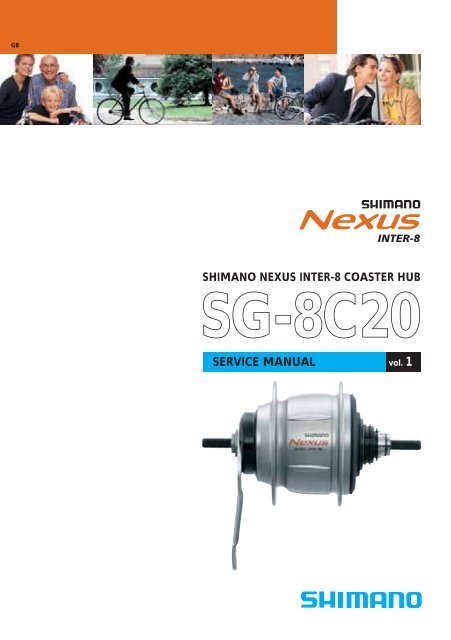
SHIMANO NEXUS INTER-8 COASTER HUB<br />
<strong>SG</strong>-<strong>8C20</strong><br />
SERVICE MANUAL<br />
vol. 1
<strong>Co</strong>ntents<br />
The new standard in internal geared hubs 4<br />
Technical Service Instructions 6<br />
<strong>SG</strong>-<strong>8C20</strong>, CJ-8S20, SL-8S20, BL-IM65<br />
Troubleshooting Chart 12<br />
Replacement of the internal unit 14<br />
Disassembly of the internal unit 16<br />
Assembly of the INTER-8 coaster hub 21<br />
Cassette Joint & Measurement tool 28<br />
NEXUS non-turn washers 30<br />
Hub dimensions (O.L.D. and axle) 31<br />
Spare parts list (<strong>SG</strong>-<strong>8C20</strong>) 32<br />
Spare parts list (SL-8S20) 33<br />
Spare parts list (CJ-8S40) 34<br />
Spare parts list (BL-IM65) 35
4<br />
The new standard in internal geared hubs<br />
The NEXUS 8-speed system delivers a new level of design, quality and function. Our designers have updated<br />
the conventional internal hub with a refreshing new design inspired by the concepts of beauty, innovation<br />
and integrity. Many technical advances have been achieved, like incorporating Shimano’s unique gear<br />
change support mechanism that makes a real low effort shifting.<br />
BR-IM70-R<br />
Roller Brake<br />
<strong>SG</strong>-<strong>8C20</strong><br />
SB-8S20 ST-8S20<br />
BL-IM65<br />
<strong>SG</strong>-8R25<br />
Premium version<br />
<strong>SG</strong>-8R20<br />
Roller Brake<br />
<strong>SG</strong>-<strong>8C20</strong><br />
<strong>Co</strong>aster Brake<br />
<strong>SG</strong>-8R25-VS<br />
<strong>SG</strong>-8R20-VS<br />
V-Brake<br />
Small Parts Set FC-NX60<br />
33/38T<br />
FC-NX80<br />
HOLLOWTECH<br />
Crankset<br />
SL-8S20<br />
BB-UN25<br />
BL-IM65<br />
<strong>SG</strong>-8R25<br />
BL-IM65<br />
3-finger<br />
Brake lever<br />
BL-IM60<br />
4-finger<br />
Brake lever<br />
ST-8S20<br />
3-finger<br />
Brake lever<br />
SL-8S20<br />
SB-8S20<br />
4-finger<br />
Brake lever
<strong>SG</strong>-8R25 Premium Version for Roller Brake<br />
<strong>SG</strong>-8R20 Roller Brake Version<br />
<strong>SG</strong>-8R25-VS V-Brake Version<br />
<strong>SG</strong>-8R20-VS V-Brake Version<br />
<strong>SG</strong>-<strong>8C20</strong> <strong>Co</strong>aster Brake Version<br />
• Gear Change Support Mechanism<br />
Shimano’s gear change support mechanism uses<br />
pedaling power to aid down-shifting. The result<br />
is fast and accurate down-shifting with an exeptionally<br />
light feeling. Mechanical shifting resistance<br />
is notably reduced so shifting is not affected<br />
under high loads.<br />
shifting torque<br />
driver rotation torque<br />
• Smooth Gear Change<br />
The smaller idling angle realizes shockless<br />
smoother shifting for stressless comfortable gear<br />
change.<br />
INTER-7 INTER-8<br />
• Smoother Rotation<br />
Shimano’s precise manufacturing abilities<br />
construct an internal hub that rotates with<br />
significantly less drag than previous models.<br />
• Close Ratio Wider Range<br />
The INTER-8 hub has increased its gear ratio to<br />
307%, compared to 244% of the INTER-7 hub.<br />
2.0<br />
1.5<br />
1.0<br />
0.5<br />
244%<br />
low-high<br />
difference<br />
0.63 (32T)<br />
0.53 (38T)<br />
20~90º<br />
0.74 (27T)<br />
0.64 (31T)<br />
0.84 (24T)<br />
0.75 (27T)<br />
0.99 (20T)<br />
0.85 (24T)<br />
1.15 (17T)<br />
1.00 (20T)<br />
10~30º<br />
1.34 (15T)<br />
1.22 (16T)<br />
1.55 (13T)<br />
1.42 (14T)<br />
1st 2nd 3rd 4th 5th 6th 7th 8th<br />
1.61 (12T)<br />
307%<br />
low-high<br />
difference<br />
• Better Sealing<br />
The INTER-8 hub has adopted a labyrinth seal<br />
system that shuts out water and dirt to extend<br />
the service life and maintain smooth shifting in all<br />
circumstances. Optionally a waterproof dust cap<br />
can be installed ex factory on the non-drive side<br />
before shipment, in case you wish to use the hub<br />
in combination with a seperate brake system such<br />
as V-Brakes.<br />
labyrinth seal<br />
• Robust <strong>Co</strong>nstruction<br />
Durable planetary and step-up gear sets assure<br />
long trouble-free service.<br />
ST-8S20 Shifter with 3-finger Brake Lever<br />
BL-IM65 3-finger Brake Lever<br />
SB-8S20 Shifter with 4-finger Brake Lever<br />
SL-8S20 Shifter<br />
BL-IM60 4-finger Brake Lever<br />
• Fast and Light Shifting<br />
In combination with the Gear Change Support<br />
Mechanism the shifting action is quick and light<br />
even during hight pedaling loads.<br />
• Easy-to-read Gear Indicator<br />
Larger more visible indicator numbers make gear<br />
positions easier to read. Additionally, indicator<br />
symbols help to understand the direction of<br />
shifting progression.<br />
• INTER-8 (<strong>SG</strong>-<strong>8C20</strong>): 30% more braking<br />
power compared to INTER-7<br />
30% more powerful<br />
3.0<br />
2.5<br />
2.0<br />
1.0<br />
0.0<br />
INTER-8<br />
INTER-7<br />
1 2 3 4 5 6 7 8<br />
5
6<br />
General Safety Information<br />
– To avoid serious<br />
WARNING injuries:<br />
• It is important to completely understand<br />
the operation of your bicycle's brake<br />
system. Improper use of your bicycle's<br />
brake system may result in a loss of<br />
control or an accident, which could lead<br />
to sever injury. Because each bicycle may<br />
handle differently, be sure to learn the<br />
proper braking technique (including<br />
bicycle control characteristics) and<br />
operation of your bicycle. This can be<br />
done by consulting your professional<br />
bicycle dealer and the bicycle owner's<br />
manual, and by practicing your riding<br />
and braking technique.<br />
• When securing the brake arm to the<br />
frame, be sure to use a brake arm clip<br />
that matches the size of the chainstay,<br />
and securely tighten them with the clip<br />
screw and clip nut to the specified<br />
tightening torque.<br />
Use a lock nut with a nylon insert (selflocking<br />
nut) for the clip nut. It is recommended<br />
that standard Shimano parts<br />
be used for the clip screw, clip nut and<br />
brake arm clip. In addition, use a brake<br />
arm clip that matches the size of the<br />
chainstay.<br />
If the clip nut comes off the brake arm,<br />
or if the clip screw or brake arm clip<br />
becomes damaged, the brake arm may<br />
rotate on the chainstay and cause the<br />
handlebars to jerk suddenly, or the<br />
bicycle wheel may lock and the bicycle<br />
may fall over, causing serious injury.<br />
• When installing the hub to the frame,<br />
be sure to install the correct non-turn<br />
washers to the left and right sides, and<br />
securely tighten the hub nuts to the<br />
specified torques. If the non-turn washers<br />
are installed to one side only, or if the<br />
hub nuts are not tightened sufficiently,<br />
the non-turn washer may fall out, which<br />
could cause the hub axle to rotate and<br />
the cassette joint to turn. This may then<br />
cause the handlebars to be accidentally<br />
pulled by the shifting cable, and an<br />
extremely serious accident could result.<br />
• Obtain and read the service instructions<br />
carefully prior to installing the parts.<br />
Loose, worn, or damaged parts may<br />
cause serious injury to the rider.<br />
We strongly recommend only using<br />
genuine Shimano replacement parts.<br />
• Check that the wheels are fastened<br />
securely before riding the bicycle. If the<br />
wheels are loose in any way, they may<br />
come off the bicycle and serious injury<br />
may result.<br />
• Read these Technical Service Instructions<br />
carefully, and keep them in a safe place<br />
for later reference.<br />
– To avoid serious<br />
CAUTION injuries:<br />
• Avoid continuous application of the<br />
brakes when riding down long slopes, as<br />
this will cause the internal brake parts to<br />
become very hot, and this may weaken<br />
braking performance. It may also cause a<br />
reduction in the amount of brake grease<br />
inside the brake, and this can lead to<br />
problems such as abnormally sudden<br />
braking.<br />
• Spin the wheel and confirm that the<br />
braking force of the coaster brake is<br />
correct.<br />
• If the brakes are used frequently, the<br />
brake drum may become hot. Do not<br />
touch the brake drum for at least<br />
30 minutes after you finish riding the<br />
bicycle.<br />
NOTE:<br />
Brake drum<br />
• You can shift gears while pedaling, but<br />
on rare occasions the pawls and ratchet<br />
inside the hub may produce some noise<br />
afterwards as part of normal gear shifting<br />
operation.<br />
• The CJ-8S20 cassette joint should only be<br />
used with sprockets from 16T to 23T.<br />
• If the wheel becomes stiff and difficult to<br />
turn, you should replace the brake shoes<br />
or lubricate with grease.<br />
• Do not apply any lubricant to the inside<br />
of the hub, otherwise the grease will<br />
come out.<br />
• You should periodically wash the sprockets<br />
in a neutral detergent and then<br />
lubricate them again. In addition, cleaning<br />
the chain with neutral detergent and<br />
lubricating it can be a effective way of<br />
extending the useful life of the sprockets<br />
and the chain.<br />
• If the chain keeps coming off the sprockets<br />
during use, replace the sprockets and<br />
the chain.<br />
• Parts are not guaranteed against natural<br />
wear or deterioration resulting from<br />
normal use.<br />
• For maximum performance we highly<br />
recommend Shimano lubricants and<br />
maintenance products.<br />
• For any questions regarding methods of<br />
handling or adjustment, please contact<br />
the place of purchase.<br />
<strong>SG</strong>-<strong>8C20</strong><br />
CJ-8S20<br />
Installation of the cassette joint<br />
to the hub<br />
1. Install the driver cap to the driver on the<br />
right side of the hub body.<br />
Driver cap<br />
Driver<br />
Driver cap<br />
2. Turn the cassette joint pulley in the<br />
direction of the arrow in the illustration<br />
to align the red ● marks on the pulley<br />
and the bracket. With the cassette joint<br />
in this condition, install it so that the<br />
red ● mark on the cassette joint is<br />
aligned with the red ● mark on the<br />
right side of the hub body.<br />
Cassette joint<br />
Align the<br />
red ● marks<br />
to install.<br />
Right side of<br />
the hub body<br />
Should be aligned<br />
CJ-8S20<br />
JAPAN<br />
Pulley<br />
Bracket<br />
CJ-8S20<br />
JAPAN<br />
SI-35P0A<br />
INTER-8 Hub<br />
with <strong>Co</strong>aster Brake<br />
Cassette Joint<br />
Technical Service Instructions<br />
Be sure to read these service instructions in<br />
conjunction with the service instructions for<br />
the INTER-8 shifting lever before use.<br />
Note the<br />
direction<br />
Align the<br />
red ● marks<br />
to install.
3. 1) Secure the cassette joint to the hub<br />
with the cassette joint fixing ring.<br />
When installing the cassette joint fixing<br />
ring, align the yellow ● mark with the<br />
yellow ● mark on the cassette joint<br />
pulley.<br />
Align the<br />
yellow ●<br />
marks to<br />
install.<br />
Cassette joint<br />
pulley<br />
LOCK<br />
JAPAN<br />
CJ-8S20<br />
CJ-8S20<br />
JAPAN<br />
CK<br />
O<br />
L<br />
Cassette joint fixing ring<br />
LOCK<br />
CJ-8S20<br />
3. 2) After installing the cassette joint fixing<br />
ring, turn it 45º clockwise.<br />
Turn 45º<br />
JAPAN<br />
Cassette joint<br />
fixing ring<br />
Fit the cassette joint bracket<br />
securely.<br />
Installation of the hub<br />
to the frame<br />
1. Mount the chain on the sprocket, and<br />
then set the hub axle into the fork ends.<br />
Hub axle<br />
Fork end<br />
2. Place the non-turn washers onto the right<br />
side and left side of the hub axle. At this<br />
time, turn the cassette joint so that the<br />
projecting parts of the non-turn washers<br />
fit into the grooves of the fork ends. If<br />
this is done, the cassette joint can be<br />
installed so that it is almost parallel to the<br />
chainstay.<br />
Non-turn washer<br />
(for left side)<br />
Chainstay<br />
7R<br />
J-8S20<br />
JAPAN<br />
C<br />
CK<br />
LO<br />
7R<br />
J-8S20<br />
JAPAN<br />
C<br />
CK<br />
Cap nut<br />
Non-turn washer<br />
Cassette joint<br />
LO<br />
Groove of<br />
fork end<br />
Non-turn<br />
washer (for<br />
right side)<br />
� Different types of left and right nonturn<br />
washers are available for use with<br />
standard and reversed fork ends. Use<br />
whichever non-turn washers are suitable.<br />
Fork end<br />
Standard<br />
Reversed<br />
Reversed<br />
(full chain<br />
case)<br />
Right<br />
5R/Yellow<br />
7R/ Black<br />
6R/Silver<br />
5R/Yellow<br />
Mark<br />
Non-turn washer<br />
Mark/<strong>Co</strong>lor<br />
Left<br />
5L/Brown<br />
7L/Gray<br />
6L/White<br />
5L/Brown<br />
� The projecting parts should be on the<br />
fork end side.<br />
� Install the non-turn washers so that the<br />
projecting parts is securely in the fork<br />
end grooves on either side of the hub<br />
axle.<br />
3. Take up the slack in the chain and secure<br />
the wheel to the frame with the cap nuts.<br />
R<br />
7<br />
Size<br />
θ �� 20ºº®<br />
θ �� 38��<br />
θ = 0��<br />
θ = 0��<br />
Tightening<br />
torque:<br />
30 – 45 N·m<br />
{260 – 390 in. lbs.}<br />
4. Fix the brake arm securely to the chainstay<br />
with the brake arm clip.<br />
Brake arm<br />
Clip nut<br />
Clip screw<br />
Brake arm clip<br />
Chainstay<br />
NOTE:<br />
• When installing the brake arm clip,<br />
securely tighten the clip screw while<br />
holding the clip nut with a 10 mm<br />
spanner.<br />
Tightening torque:<br />
2 – 3 N·m {17 – 26 in. lbs.}<br />
• After installing the brake arm clip,<br />
check that the clip screw protrudes<br />
about 2 – 3 mm from the surface of the<br />
clip nut.<br />
Clip nut<br />
2 – 3 mm<br />
Brake arm<br />
Brake arm clip<br />
Clip screw<br />
(M6 x 16 mm)<br />
5. Before using the <strong>Co</strong>aster Brake, check<br />
that the brake works properly and that<br />
the wheel turns smoothly.<br />
7
General Safety Information<br />
– To avoid serious<br />
WARNING injuries:<br />
• Obtain and read the service instructions<br />
carefully prior to installing the<br />
parts. Loose, worn, or damaged<br />
parts may cause serious injury to the<br />
rider.<br />
We strongly recommend only using<br />
genuine Shimano replacement parts.<br />
• It is important to completely understand<br />
the operation of your bicycle's<br />
brake system. Improper use of your<br />
bicycle's brake system may result in a<br />
loss of control or an accident, which<br />
could lead to severe injury. Because<br />
each bicycle may handle differently,<br />
be sure to learn the proper braking<br />
technique (including brake lever<br />
pressure and bicycle control characteristics)<br />
and operation of your bicycle.<br />
This can be done by consulting<br />
your professional bicycle dealer and<br />
the bicycle's owners manual, and by<br />
practicing your riding and braking<br />
technique.<br />
• These brake levers are equipped<br />
with a mode switching mechanism<br />
to make them compatible with<br />
cantilever brakes and Roller Brakes<br />
or V-Brakes with power modulator.<br />
If the incorrect mode is selected it<br />
may cause either excessive or insufficient<br />
braking force to occur, which<br />
could result in dangerous accidents.<br />
Be sure to select the mode in accordance<br />
with the instructions given in<br />
the table below.<br />
8<br />
Mode<br />
position<br />
C/R position<br />
V<br />
V<br />
V<br />
C R<br />
V<br />
C R<br />
The C indicates the<br />
mode position for compatibility<br />
with cantilever<br />
brakes.<br />
The R indicates the<br />
mode position for compatibility<br />
with Roller<br />
Brakes.<br />
V position<br />
C R<br />
C R<br />
The V indicates the<br />
mode position for<br />
compatibility with<br />
V-Brakes with power<br />
modulator.<br />
Use the brake levers with mode<br />
switching mechanism in the combinations<br />
given above.<br />
• Read these Technical Service<br />
Instructions carefully, and keep them<br />
in a safe place for later reference.<br />
CAUTION<br />
Applicable<br />
brake<br />
• Cantilever<br />
brakes<br />
• Roller<br />
Brakes<br />
• V-Brakes<br />
with<br />
power<br />
modulator<br />
– To avoid<br />
serious injuries:<br />
Be sure to shift the lever one gear at<br />
a time, and reduce the force being<br />
applied to the pedals during shifting.<br />
If you try to force operation of the<br />
shifting lever while the pedals are<br />
being turned strongly, your feet may<br />
come off the pedals and the bicycle<br />
may topple over, which could result<br />
in serious injury.<br />
NOTE:<br />
• For maximum performance we highly<br />
recommend Shimano lubricants<br />
and maintenance products.<br />
• Parts are not guaranteed against<br />
natural wear or deterioration resulting<br />
from normal use.<br />
SL-8S20<br />
BL-IM65<br />
CJ-8S20<br />
SI-6FD0A<br />
Revo-shift<br />
Lever<br />
Brake Lever<br />
Cassette Joint<br />
Technical Service Instructions<br />
Be sure to read these service<br />
instructions in conjunction with<br />
the service instructions for the<br />
Inter-8 hub before use.<br />
Revo-shift lever operation<br />
Turn the Revo-shift lever to shift to<br />
each of the eight gears.<br />
Indicator<br />
Pedaling becomes heavier<br />
Indicator moves toward ➇<br />
Pedaling becomes lighter<br />
Indicator moves toward ➀<br />
Revo-shift lever<br />
Installation of the lever<br />
Install the lever as shown in the illustration.<br />
In case of using Shimano<br />
half grip, the straight<br />
section of the handlebar<br />
should be 166 mm or<br />
more in length; attach<br />
the Revo-shift lever to<br />
this straight section.<br />
Clamp bolt<br />
3<br />
Tighten<br />
3 mm Allen<br />
key<br />
1<br />
Tightening torque:<br />
2 – 2.5 N·m<br />
{20 – 25 kgf·cm}<br />
2<br />
Leave a gap<br />
of 0.5 mm<br />
between the<br />
Revo-shift<br />
lever and the<br />
half grip.<br />
Handlebar<br />
� 22.2 mm<br />
1<br />
� 22.2 mm<br />
Half grip<br />
3<br />
Tighten<br />
2<br />
Clamp bolt<br />
5 mm Allen<br />
key<br />
Tightening torque:<br />
6 – 8 N·m Grip {60 – 80 kgf·cm}<br />
Disconnecting the shifting cable<br />
when removing the rear wheel from<br />
the frame<br />
Disconnect the cable from the<br />
cassette joint when removing the<br />
rear wheel from the frame.<br />
CJ-8S20<br />
JAPAN<br />
LOCK<br />
CJ-8S20<br />
JAPAN<br />
LOCK<br />
LOCK<br />
CJ-8S20<br />
JAPAN<br />
CJ-8S20<br />
NOTE:<br />
If reusing the cable, refer to steps<br />
7 to 9 in "Installation of the shifting<br />
cable".<br />
JAPAN<br />
Cassette<br />
joint<br />
1. Set the Revo-shift lever to ➀.<br />
2. Pull the outer casing out from<br />
the outer casing holder of the<br />
cassette joint, and then remove<br />
the inner cable from the slit in<br />
the bracket.<br />
Bracket<br />
Outer casing holder<br />
Pull out from<br />
outer casing<br />
holder.<br />
1<br />
Slit<br />
2<br />
Remove from the slit.<br />
3. Remove the inner cable fixing<br />
bolt unit from the cassette joint<br />
pulley.<br />
Inner cable fixing bolt unit<br />
Cassette joint pulley<br />
If it is difficult to pull the outer<br />
casing out from the outer casing<br />
holder of the cassette joint, insert<br />
a 2 mm Allen key or a #14 spoke<br />
into the hole in the cassette joint<br />
pulley, and then turn the pulley<br />
to loosen the inner cable. Then<br />
remove the inner cable fixing bolt<br />
unit from the pulley first, and<br />
after this remove the outer casing<br />
from the outer casing holder.<br />
2<br />
Remove the<br />
inner cable fixing<br />
bolt unit<br />
1<br />
Turn the<br />
pulley<br />
Set to ➀<br />
3<br />
Pull out<br />
from the<br />
outer casing<br />
holder<br />
Pulley hole<br />
2 mm Allen key or<br />
#14 spoke<br />
Use a shifting cable with one<br />
inner cable drum.<br />
Cable with one inner cable drum /<br />
SIS-SP40 (4 mm dia.)<br />
1. Set the Revo-shift lever to ➀.<br />
Set to ➀<br />
■ Revo-shift lever side<br />
2. Loosen the cover fixing screw, and<br />
then remove the upper cover.<br />
<strong>Co</strong>ver fixing screw<br />
Upper cover<br />
3. Pass the inner cable from the hole<br />
in the winder unit through the<br />
hole in the cable adjustment bolt.<br />
Next, insert the inner cable into<br />
the groove of the cable guide,<br />
and pull the inner cable so that<br />
the inner cable drum fits into the<br />
recess in the winder unit.<br />
2<br />
Installation of the<br />
shifting cable<br />
Hole in cable<br />
adjustment bolt<br />
Groove in cable guide<br />
3<br />
1<br />
4<br />
Recess in winder unit<br />
Hole in<br />
winder unit<br />
4. Replace the upper cover and<br />
tighten the cover fixing screw.<br />
Tightening torque:<br />
0.1 – 0.2 N·m {1 – 2 kgf·cm}<br />
<strong>Co</strong>ver fixing screw<br />
Upper cover
5. Pass the inner cable through the<br />
SIS-SP40 outer casing through the<br />
end with the plastic cap.<br />
Aluminium cap<br />
Plastic cap<br />
If cutting the outer casing, cut it near the<br />
end with the plastic cap while the cap is<br />
still attached. Then make the cut end<br />
perfectly round and attach the plastic cap.<br />
■ Cassette joint side<br />
6. After checking that the end of the<br />
outer casing is sitting securely in<br />
the cable adjustment bolt of the<br />
Revo-shift lever, attach the inner<br />
cable fixing bolt unit to the inner<br />
cable.<br />
Inner cable fixing bolt unit<br />
Note: Do not use this inner cable fixing bolt<br />
unit with the CJ-4S30 cassette joint.<br />
10 mm<br />
(Black)<br />
7. Bring the cable around to the<br />
cassette joint pulley, hold so that<br />
the inner cable fixing nut is facing<br />
to the outside (toward the fork<br />
end), and then slide the flats part<br />
of the inner cable fixing washer<br />
into the gap in the pulley.<br />
Inner cable<br />
fixing nut<br />
Remove the plastic cap.<br />
Make the cut end<br />
perfectly round.<br />
Attach the plastic cap.<br />
Pass the inner cable<br />
through the hole.<br />
101 mm<br />
LOCK<br />
Inner cable fixing<br />
nut<br />
Inner cable fixing<br />
washer<br />
Inner cable fixing<br />
bolt<br />
Pulley<br />
CJ-8S20<br />
JAPAN<br />
Plastic cap<br />
Pull the inner cable while attaching the inner<br />
cable fixing bolt unit.<br />
Tightening torque:<br />
4 – 6 N·m {40 – 60 kgf·cm}<br />
Flats part of inner<br />
cable fixing washer<br />
8. Turn the cable 60º counterclockwise<br />
and attach it to the hook.<br />
Hook<br />
Turn the<br />
cable 60º<br />
CJ-8S20<br />
JAPAN<br />
LOCK<br />
10 cm<br />
CJ-8S20<br />
JAPAN<br />
LOCK<br />
CJ-8S20<br />
JAPAN<br />
LOCK<br />
LOCK<br />
CJ-8S20<br />
9. Attach the inner cable to the pulley<br />
as shown in the illustration, pass the<br />
inner cable through the slit in the<br />
cassette joint bracket, and then<br />
insert the end of the outer casing<br />
securely into the outer casing holder.<br />
Inner cable<br />
JAPAN<br />
Pulley<br />
Bracket<br />
Bracket<br />
Outer casing holder<br />
Insert into<br />
the outer<br />
2 casing<br />
holder<br />
Slit<br />
1<br />
Pass through the slit<br />
If first inserting the outer casing into the<br />
outer casing holder is easier, then first insert<br />
the outer casing into the outer casing holder,<br />
and then insert a 2 mm Allen key or a<br />
#14 spoke into the hole in the cassette joint<br />
pulley, and then turn the pulley so that the<br />
inner cable fixing bolt unit fits into the gap<br />
in the pulley.<br />
Insert the inner<br />
cable fixing bolt<br />
unit.<br />
2<br />
Turn the<br />
pulley<br />
3 1<br />
CJ-8S20<br />
JAPAN<br />
Hole in pulley<br />
2 mm Allen key or #14 spoke<br />
Note:<br />
Check that the inner cable is correctly seated<br />
inside the pulley guide.<br />
Guide Guide<br />
OK Not OK<br />
Gap in pulley 10. Secure the cable to the frame with<br />
the outer casing bands.<br />
10 cm 15 cm<br />
Outer casing bands<br />
Insert into the<br />
outer casing<br />
holder.<br />
LOCK<br />
CJ-8S20<br />
JAPAN<br />
Adjusting the cassette joint<br />
1. Set the Revo-shift lever to ➃.<br />
Check to be sure that the yellow setting<br />
lines on the cassette joint bracket and<br />
pulley are aligned at this time.<br />
Set to ➃<br />
JAPAN<br />
CJ-8S20<br />
CK<br />
O<br />
L<br />
LOCK<br />
LOCK<br />
CJ-8S20<br />
JAPAN<br />
CJ-8S20<br />
If the yellow setting lines are not aligned,<br />
turn the cable adjustment bolt of the<br />
Revoshift lever to align the setting lines.<br />
After this, move the Revo-shift lever once<br />
more from ➃ to ➀ and then back to ➃,<br />
and then recheck to be sure that the yellow<br />
setting lines are aligned.<br />
Cable adjustment bolt<br />
Yellow setting lines<br />
The yellow setting lines on the cassette joint<br />
are located in two places. Use the one that<br />
is easiest to see.<br />
When bicycle is standing up<br />
Cassette joint<br />
bracket<br />
2. After adjusting the cassette joint, cut<br />
off the excess length of inner cable<br />
and then install the inner end cap.<br />
JAPAN<br />
When bicycle is upside down<br />
Cassette joint<br />
bracket<br />
15 – 20 mm<br />
Should be straight<br />
Should be straight<br />
CJ-8S20<br />
JAPAN<br />
CK<br />
LO<br />
Cassette<br />
joint pulley<br />
Cassette<br />
joint pulley<br />
Inner end cap<br />
9
10<br />
General Safety Information<br />
WARNING<br />
– To avoid serious injuries:<br />
• Obtain and read the service instructions<br />
carefully prior to installing the parts. Loose,<br />
worn, or damaged parts may cause serious<br />
injury to the rider.<br />
We strongly recommend only using genuine<br />
Shimano replacement parts.<br />
• Read these Technical Service Instructions<br />
carefully, and keep them in a safe place for<br />
later reference.<br />
NOTE:<br />
• The CJ-8S40 cassette joint should only be<br />
used with sprockets from 16T to 23T.<br />
• When lubricating the chain or the sprockets,<br />
be careful not to get any oil on the<br />
rubber bellows or the rubber cover of the<br />
cassette joint.<br />
• For maximum performance we highly<br />
recommend Shimano lubricants and<br />
maintenance products.<br />
• Parts are not guaranteed against natural<br />
wear or deterioration resulting from normal<br />
use.<br />
CJ-8S40<br />
Technical Service Instructions<br />
CJ-8S40 CJ-8S40<br />
JAPAN JAPAN<br />
CJ-8S40 CJ-8S40<br />
LOCK LOCK<br />
JAPAN JAPAN<br />
SI-74Y0A<br />
Refer to the Service Instructions for the INTER-8 hub for<br />
details on installation of the cassette joint to the hub<br />
and installation of the non-turn washer.<br />
7R 7R<br />
• The projecting parts should be<br />
on the fork end side.<br />
• Install the non-turn washers so that the projecting<br />
parts are securely in the fork end grooves<br />
on either side of the hub axle.<br />
Disconnecting the shifting cable when removing the rear wheel from the frame<br />
Disconnect the cable from the cassette joint when<br />
removing the rear wheel from the frame.<br />
1. Set the shifting lever to ➀.<br />
2<br />
Remove the<br />
rubber bellows<br />
from the slit<br />
Cassette Joint<br />
Set to ➀<br />
Cassette joint<br />
2. Hold the rubber cover and pull the outer casing<br />
holder out from the outer casing holder section<br />
of the cassette joint. Then remove the inner<br />
cable attached to the rubber bellows from the<br />
slit in the bracket. Be careful not to damage the<br />
rubber bellows at this time.<br />
Rubber bellows<br />
1<br />
Pull out the<br />
outer casing<br />
holder<br />
Rubber cover<br />
Note:<br />
Do not remove the cable by pulling the outer<br />
casing.<br />
Installation of the cassette joint Installation of the shifting cable<br />
Note:<br />
• Different types of left and right non-turn washers<br />
are available for use with standard and<br />
reversed fork ends. Use whichever non-turn<br />
washers are suitable.<br />
Fork end<br />
Standard<br />
Reversed<br />
Reversed<br />
(full chain<br />
case)<br />
Mark<br />
3. Remove the inner cable fixing bolt unit from<br />
the cassette joint pulley.<br />
Inner cable fixing bolt unit<br />
Cassette joint pulley<br />
LOCK LOCK<br />
LOCK LOCK<br />
CJ-8S40<br />
JAPAN<br />
CJ-8S40<br />
JAPAN<br />
If it is difficult to pull the outer casing holder<br />
out from the outer casing holder section of the<br />
cassette joint, insert a 2mm Allen key or a #14<br />
spoke into the hole in the cassette joint pulley,<br />
and then turn the pulley to loosen the inner<br />
cable. Then remove the inner cable fixing bolt<br />
unit from the pulley first, and after this remove<br />
the outer casing holder from the outer casing<br />
holder section.<br />
2<br />
Remove the inner 3<br />
cable fixing bolt unit Remove the<br />
outer casing<br />
holder<br />
1<br />
Turn the<br />
pulley<br />
Right<br />
5R/Yellow<br />
7R/ Black<br />
6R/Silver<br />
5R/Yellow<br />
Non-turn washer<br />
Mark/<strong>Co</strong>lor<br />
Left<br />
5L/Brown<br />
7L/Gray<br />
6L/White<br />
5L/Brown<br />
Pulley hole<br />
2mm Allen key<br />
or #14 spoke<br />
Note:<br />
If reusing the cable, refer to steps 6 to 8 in<br />
“Installation of the shifting cable”.<br />
.<br />
Size<br />
θ �� 20��<br />
θ �� 38��<br />
θ = 0��<br />
θ = 0��<br />
Use a shifting cable with one inner cable drum.<br />
SIS-SP (4 mm or 5 mm dia.)<br />
Shifting lever end<br />
Shield cap<br />
Note:<br />
Make sure that the shield cap is at the shifting<br />
lever end.<br />
■ Shifting lever side<br />
1. <strong>Co</strong>nnect the shifting cable to the shifting lever.<br />
■ Cassette joint side<br />
2. Set the shifting lever to ➀.<br />
Cassette joint end<br />
Refer to the Service Instructions which are<br />
provided with the INTER-8 shifting lever.<br />
3. Install the rubber cover and rubber bellows to<br />
the outer casing holder.<br />
Rubber bellows Outer casing<br />
holder<br />
Rubber cover<br />
4. Wipe away any grease which may be on the inner<br />
cable, and then pass the inner cable through the<br />
rubber bellows. After this, insert the outer casing<br />
into the rubber cover and set it into the outer<br />
casing holder.<br />
Use a new inner cable. Do not use a cable<br />
which has had the end cut off.<br />
1) While holding the end of the rubber bellows, insert<br />
the inner cable. Be careful not to pierce the rubber<br />
bellows with the end of the inner cable at this time.<br />
End of rubber bellows<br />
Set to ➀<br />
Be careful of the inner cable end.<br />
OK Not OK<br />
Not OK<br />
2) Slide the rubber bellows onto the inner cable.<br />
Rubber bellows<br />
Inner cable
3) Push the outer casing on so that it securely<br />
touches the outer casing holder.<br />
Inner cable Outer casing holder<br />
Rubber bellows Rubber cover<br />
5. After checking that the end of the outer<br />
casing is sitting securely in the cable adjustment<br />
bolt of the shifting lever, attach the<br />
inner cable fixing bolt unit to the inner cable.<br />
10 mm<br />
(Black)<br />
Turn the<br />
cable 60°<br />
Inner cable fixing bolt unit<br />
127 mm<br />
LOCK LOCK<br />
CJ-8S40<br />
JAPAN<br />
LOCK LOCK<br />
CJ-8S40<br />
JAPAN<br />
Outer casing<br />
Note: Do not use this inner cable fixing bolt unit<br />
with the CJ-4S30 cassette joint.<br />
Pass the inner cable through the hole.<br />
Tightening torque:<br />
4 – 6 N·m (40 – 60 kgfcm)<br />
6. Bring the cable around to the cassette joint<br />
pulley, hold so that the inner cable fixing nut<br />
is facing to the outside (toward the fork<br />
end), and then slide the flats part of the<br />
inner cable fixing washer into the gap in the<br />
pulley.<br />
Inner cable<br />
fixing nut<br />
7. Turn the cable 60° counterclockwise and<br />
attach it to the hook.<br />
Hook<br />
Flats part of inner<br />
cable fixing washer<br />
Pulley<br />
Inner cable fixing nut<br />
Inner cable fixing<br />
washer<br />
Inner cable fixing bolt<br />
63 mm or less<br />
Pull the inner cable while attaching<br />
the inner cable fixing bolt unit.<br />
Gap in pulley<br />
8. Attach the inner cable to the pulley as shown in<br />
the illustration, pass the part of the inner cable<br />
which has the rubber bellows attached through<br />
the slit in the cassette joint bracket, and then<br />
insert the outer casing holder securely into the<br />
outer casing holder section. Be careful not to<br />
damage the rubber bellows at this time.<br />
Inner cable<br />
CJ-8S40 CJ-8S40<br />
JAPAN JAPAN<br />
Pulley<br />
Insert the inner<br />
cable fixing bolt<br />
unit<br />
LOCK LOCK<br />
CJ-8S40<br />
JAPAN<br />
10 cm<br />
LOCK LOCK<br />
LOCK LOCK<br />
CJ-8S40 CJ-8S40<br />
JAPAN JAPAN<br />
Outer casing holder section<br />
Slit<br />
Rubber bellows<br />
Outer casing holder<br />
Rubber<br />
cover<br />
CJ-8S40<br />
JAPAN<br />
Bracket<br />
If first inserting the outer casing holder into<br />
the outer casing holder section of the cassette<br />
joint is easier, then first insert the outer<br />
casing holder into the outer casing holder<br />
section of the cassette joint, and then insert<br />
a 2mm Allen key or a #14 spoke into the hole<br />
in the cassette joint pulley, and then turn the<br />
pulley so that the inner cable fixing bolt unit<br />
fits into the gap in the pulley.<br />
2<br />
Turn the<br />
pulley<br />
Hole in pulley<br />
2 mm Allen key or #14 spoke<br />
Insert the<br />
1<br />
rubber bellows<br />
into the slit<br />
2 Attach the<br />
outer casing<br />
holder<br />
3 1<br />
10 cm 15 cm<br />
Attach the<br />
outer casing<br />
holder<br />
Note: Check that the inner cable is correctly<br />
seated inside the pulley guide.<br />
Guide Guide<br />
OK<br />
Not OK<br />
Outer casing bands<br />
LOCK LOCK<br />
CJ-8S40<br />
JAPAN<br />
9. Secure the cable to the frame with the outer<br />
casing bands.<br />
Adjusting the cassette joint<br />
1. Set the shifting lever to ➃.<br />
Check to be sure that the yellow setting lines<br />
on the cassette joint bracket and pulley are<br />
aligned at this time.<br />
Yellow setting lines<br />
Set to ➃<br />
The yellow setting lines on the cassette joint<br />
are located in two places. Use the one that is<br />
easiest to see.<br />
Cassette joint bracket<br />
15 – 20 mm<br />
When bicycle is standing up<br />
JAPAN<br />
LOCK CJ-8S40<br />
Cassette joint bracket<br />
Should be straight<br />
LOCK CJ-8S40<br />
JAPAN<br />
LOCK<br />
CJ-8S40<br />
If the yellow setting lines are not aligned, turn<br />
the cable adjustment bolt of the shifting lever<br />
to align the setting lines. After this, move the<br />
shifting lever once more from ➃ to ➀ and then<br />
back to ➃, and then re-check to be sure that<br />
the yellow setting lines are aligned.<br />
2. After adjusting the cassette joint, cut off the<br />
excess length of inner cable and then install<br />
the inner end cap.<br />
JAPAN<br />
When bicycle is upside down<br />
Should be straight<br />
Cable adjustment bolt<br />
Inner end cap<br />
CJ-8S40<br />
JAPAN<br />
LOCK<br />
Cassette joint<br />
pulley<br />
Cassette joint<br />
pulley<br />
11
12<br />
Troubleshooting Chart<br />
SHIMANO NEXUS INTER-8 <strong>Co</strong>aster Hub<br />
<strong>SG</strong>-<strong>8C20</strong><br />
2 3<br />
35<br />
36 37<br />
CJ-8S20<br />
1<br />
29<br />
25 26 27 28<br />
19 20 21 22 23 24<br />
Internal Assembly<br />
30 31 32 34 19<br />
Abnormal noise<br />
occurs.<br />
4<br />
5 6 7<br />
Same treatment of 8R20<br />
Abnormal noise<br />
still occurs after<br />
adjusting cable.<br />
Trouble condition Remedy<br />
Cable is incorrectly<br />
adjusted.<br />
While<br />
shifting<br />
While<br />
pedaling<br />
1<br />
8 9 10 11 12 13 14 15 16 17 18<br />
Shifting<br />
position<br />
Shifting<br />
position<br />
1��2<br />
2��3<br />
3��4<br />
6��7<br />
7��8<br />
5��6<br />
All<br />
Set the shift lever to 4th. Then turn the cable<br />
adjusting barrel to align the red setting lines<br />
on the cassette joint bracket and pulley.<br />
Shift down to the 1st gear, up to<br />
the 4th again and recheck the adjustment.<br />
Replace the hub axle unit and<br />
carrier unit.<br />
Replace the hub axle unit, clutch unit<br />
and carrier unit.<br />
Replace the driver unit, hub axle unit<br />
and carrier unit.<br />
33<br />
38<br />
39<br />
40<br />
41<br />
Internal Hub<br />
Grease<br />
(For coaster brake also)<br />
TL-8S30<br />
TL-8S20<br />
TL-8S11<br />
04<br />
PE-LD
Troubleshooting Chart<br />
Gear shift<br />
is not<br />
possible.<br />
While<br />
pedaling.<br />
While not<br />
pedaling.<br />
While<br />
braking.<br />
Cable is incorrectly<br />
adjusted.<br />
Remove the wheel<br />
from the frame and<br />
check whether gear<br />
shifting is possible.<br />
Shifting lever indicator doesn’t match hub<br />
shifting position.<br />
Turning is stiff.<br />
Gear Unsmooth<br />
<strong>Co</strong>ne Unsmooth<br />
Trouble condition Remedy<br />
Free rotation is stiff.<br />
Following treatment is for 8C<br />
Braking is too sudden.<br />
Gear shifting is<br />
possible:<br />
When the shifting<br />
lever doesn’t<br />
operate.<br />
Gear shifting is not<br />
possible.<br />
When the hub<br />
doesn’t work.<br />
4.8<br />
Except 4.8<br />
4.8<br />
Except 4.8<br />
Set the shift lever to 4th. Then turn the<br />
cable adjusting barrel to align the red<br />
setting lines on the cassette joint<br />
bracket and pulley.<br />
Replace the shifting lever.<br />
Replace the carrier unit and<br />
hub axle unit.<br />
Replace the carrier unit and hub axle<br />
unit.<br />
Replace the hub axle unit and<br />
carrier unit.<br />
Replace the carrier unit.<br />
Replace the hub axle unit and<br />
carrier unit.<br />
Replace the carrier unit.<br />
Replace the right hand cone and<br />
driver.<br />
Replace the shell, ball retainer and<br />
driver unit.<br />
Trouble condition Remedy<br />
Replace the brake shoe unit, Driver<br />
unit & axle unit.<br />
Braking force is weak. Replace the brake shoe unit.<br />
Pedal turning angle for brake<br />
to operate is too large.<br />
Wheels lock when bicycle is pushed backward.<br />
A squeaking sound caused by lack of lubrication<br />
can be heard.<br />
Replace the brake shoe unit, Driver<br />
unit& axle unit.<br />
Replace carrier unit, driver unit and<br />
clutch unit.<br />
Apply grease or replace the brake<br />
shoe unit.<br />
Brakes do not release. Replace the brake shoe unit and<br />
carrier unit.<br />
13
14<br />
Replacement of the internal unit<br />
<strong>SG</strong>-<strong>8C20</strong><br />
Note:<br />
Unit parts should never be<br />
disassembled. If they are,<br />
problems may result.<br />
When replacing parts, replace<br />
the whole internal assembly or<br />
whole unit part.<br />
Tools<br />
Note:<br />
Unit parts should never be<br />
disassembled. If they are,<br />
problems may result.<br />
When replacing parts, replace<br />
the whole internal assembly or<br />
whole unit part.<br />
Note:<br />
For internal unit replacement<br />
only tools "e" and "f" are<br />
necessary.<br />
1. Hold the two bevelled<br />
surfaces of the hub axle on<br />
the brake arm side in a vice<br />
and remove the dust cap.<br />
2. Turn the hub upside down<br />
and hold the two bevelled<br />
surfaces of the hub axle on<br />
the sprocket side in a vice.<br />
Note:<br />
Do not damage<br />
the threads of<br />
the hub axle.<br />
a<br />
b<br />
d<br />
c e f<br />
a: Hammer<br />
b: TL-8S11<br />
Right Hand <strong>Co</strong>ne Removal Tool<br />
Part No. Y-708 00600<br />
c: TL-8S20<br />
Right Hand <strong>Co</strong>ne Installation Tool<br />
Part No. Y-708 00200<br />
d: TL-8S30<br />
Carrier Unit Alignment tool<br />
Part No. Y-708 00300<br />
e: Screwdriver<br />
f: TL-7S20<br />
Hub Spanners 17mm x 22mm (2 pcs.)<br />
Part No. 3-130 9890<br />
(We recommend the use of protective glasses<br />
during disassembly and assembly)<br />
Note:<br />
Do not damage the threads of<br />
the hub axle.<br />
Vice<br />
Remove the left hand locknut<br />
from the hub axle, and then<br />
remove the stop nut.<br />
TL-7S20<br />
Locknut 17mm (Y-35P 28000)<br />
Stop Nut 22mm (Y-35P 22000)
3. Remove the brake arm unit<br />
and ball retainer B from the<br />
hub axle.<br />
4. Remove the hub shell.<br />
Now it can be replaced<br />
with the new internal<br />
assembly.<br />
Disassembly and assembly can be<br />
carried out quickly.<br />
Part No. 36P 98010<br />
Brake arm unit<br />
Ball retainer B<br />
Hub shell<br />
Internal assembly<br />
15
16<br />
Disassembly of the internal unit<br />
1. Remove the brake shoe unit.<br />
2. Carefully remove the stop ring<br />
with a screwdriver. Because<br />
the stop ring will tend to<br />
come off with some force,<br />
use a piece of cloth to prevent<br />
loss.<br />
3. Remove carrier unit and ring<br />
gear by lifting straight up.<br />
Do not rotate to disengage.<br />
4. Remove the ring gear slide<br />
spring with a screwdriver.<br />
Ring gear slide spring<br />
(Y-35P 12000)<br />
Brake shoe unit<br />
Screwdriver<br />
Stop ring<br />
(Y-33Y 19000)<br />
Carrier unit (Y-35P 98040)<br />
Ring gear slide spring (Y-35P 12000)<br />
Ring gear 1<br />
(Y-35P 11000)
5. Remove ball retainer O<br />
(3/16"X26) while pushing<br />
pawls B.<br />
6. Reverse axle unit in vice to<br />
access the drive side cone<br />
assembly.<br />
7. Remove the locknut with a<br />
17mm hub spanner.<br />
8. Remove the stop washer.<br />
Pawls B<br />
Ball retainer O<br />
(Y-34R 98030)<br />
Right hand locknut<br />
(Y-33Z 07020)<br />
Stop washer<br />
(Y-34R 09000)<br />
17
18<br />
9. Remove the lock washer.<br />
10. Remove the driver plate.<br />
11. Support the driver assembly<br />
on the vice, as shown. Set<br />
cone removal tool (TL-8S11)<br />
into the groove such that<br />
the pawl A is contacting the<br />
notch in the tool, see detail.<br />
Strike the tool with the<br />
hammer until cone and<br />
axle unit are separated.<br />
Lock washer<br />
(Y-34R 98090)<br />
Driver plate<br />
(Y-34R 12000)<br />
Tool TL-8S11<br />
(Y-708 00600)<br />
A
12. Reverse the right hand cone.<br />
13. Remove the ball retainer P<br />
(3/16"X13).<br />
14. Remove the driver unit.<br />
15. Remove the return spring A.<br />
Right hand cone<br />
(Y-34R 98080)<br />
Ball retainer P<br />
(Y-34R 98070)<br />
Driver unit<br />
(Y-35P 98070)<br />
Return spring A<br />
(Y-34R 21000)<br />
19
20<br />
16. Remove the clutch unit by<br />
turning it counterclockwise<br />
and aligning the two teeth<br />
to the two grooves, as<br />
shown.<br />
This completes the disassembly of<br />
the INTER-8 coaster hub.<br />
Clutch unit<br />
(Y-35P 98060)
Assembly of the INTER-8 coaster hub<br />
1. With the hub axle unit mounted<br />
in a vice, align the two<br />
teeth on the clutch unit with<br />
the two notches in the hub<br />
axle unit. Turn the clutch unit<br />
clockwise until it is in its final<br />
position as shown.<br />
Clutch unit<br />
(Y-35P 98060)<br />
2. Install the return spring with<br />
the largest coil downward.<br />
The spring should sit in the<br />
groove on the clutch unit,<br />
shown as a blue line in the<br />
picture. Be careful not to<br />
install the return spring A<br />
upside down.<br />
3. Assemble the driver unit by<br />
aligning the more shallow<br />
notch on the driver unit<br />
with the wider tooth on the<br />
clutch unit. Rotate the driver<br />
counterclockwise to hold the<br />
compressed spring in position.<br />
Clutch unit<br />
(Y-34R 98050)<br />
NOTE:<br />
During the assembly procedures<br />
coat all seals, gears and pawl<br />
assemblies with a thin coat of<br />
Nexus specific grease. Where<br />
indicated by blue grease icon,<br />
apply grease liberally.<br />
(Y-041020800)<br />
Return spring A<br />
(Y-34R 21000)<br />
Set drive unit<br />
while turn it<br />
counterclockwise.<br />
NOTE:<br />
Assemble the driver<br />
unit while pushing<br />
pawls B as shown in<br />
the picture.<br />
21
22<br />
4. Install the ball retainer P<br />
(3/16"X13).<br />
5. When installing the right hand<br />
cone, align the two serrations<br />
with the grooves in the axle,<br />
as shown. Set the cone installation<br />
tool (TL-8S20) and strike<br />
it until it comes to a stop.<br />
NOTE:<br />
Make sure the right hand cone is<br />
completely seated, as shown, and<br />
the seal is installed equally.<br />
6. Install the driver plate. Be<br />
careful of the setting direction<br />
as shown in the picture.<br />
Driver plate<br />
(Y-34R 12000)<br />
Ball retainer P<br />
(Y-34R 98070)<br />
(Y-041020800)<br />
Right hand cone<br />
(Y-34R 98080)<br />
seal seal<br />
ok<br />
Tool TL-8S20<br />
(Y-708 00200)<br />
ok
7. Install the lock washer.<br />
8. When installing the stop<br />
washer, align the two teeth<br />
with the two grooves of the<br />
lock washer.<br />
9. Install the right hand locknut<br />
with a 17mm hub spanner.<br />
NOTE:<br />
If either the lock washer or driver<br />
plate rotates during this step,<br />
return to assembly step 5 and<br />
make sure that the cone is correctly<br />
seated.<br />
10. Reverse the axle unit in the<br />
vice to complete assembly.<br />
Lock washer<br />
(Y-34R 98090)<br />
Stop washer<br />
(Y-34R 09000)<br />
Tightening torque:<br />
25 - 30 N·m {218 - 261 in.lbs}<br />
Right hand locknut<br />
(Y-33Z 07020)<br />
(Y-041020800)<br />
23
24<br />
11. Install the ball retainer O<br />
(3/16“ X 26) while pushing<br />
pawls B one by one.<br />
Be careful not to displace<br />
pawls B on the driver unit.<br />
12. How to align the three<br />
planetary gears and install<br />
the ring gear.<br />
(Without any tools)<br />
Align the three marks, which are<br />
on the planetary gears, as shown<br />
in the picture.<br />
Tool TL-8S30<br />
(Y-708 00300)<br />
(With tool)<br />
Align the grooves of the tool with<br />
the marks on the planetary gears.<br />
The purpose of the tool is to fix<br />
the planetary gear's position.<br />
Now you can install the ring gear.<br />
Install the ring gear slide spring<br />
with a screwdriver.<br />
Ring gear 1 stop ring<br />
(Y-34R 80000)<br />
Carrier unit<br />
(Y-35P 98040)<br />
Ball retainer O<br />
(Y-34R 98030)<br />
(Y-041 20800)<br />
(Y-041 20800)<br />
(Y-041 20800)<br />
Pawls B<br />
Ring gear 1<br />
(Y-35P 11000)
13. Align the internal tooth on<br />
the ring gear and carrier unit<br />
with the groove in the hub<br />
axle unit. Install ring gear<br />
and carrier unit slowly.<br />
(Y-041020800)<br />
NOTE:<br />
Be careful to fit A to A and B to B<br />
of the driver unit and the hub<br />
axle unit as shown in the picture.<br />
Important:<br />
To set all four pawls in the correct<br />
position.<br />
Use a flat blade screwdriver to<br />
depress pawls, as shown, during<br />
assembly. Turn unit and check<br />
that all pawls are in the proper<br />
position.<br />
A<br />
B<br />
(Y-041 20600)<br />
Pawls<br />
B<br />
A<br />
25
26<br />
14. Insert the stop ring.<br />
NOTE:<br />
If there is no visible groove to<br />
receive the stop ring, it is likely<br />
that the ring gear and carrier unit<br />
are not properly assembled,<br />
return to assembly step 13.<br />
15. Install the brake shoe unit.<br />
16. Install the hub shell unit<br />
while turning it counterclockwise.<br />
17. Place ball retainer B onto the<br />
hub shell.<br />
Ball retainer B<br />
(Y-330 98110)<br />
(Y-041020800)<br />
Stop ring<br />
(Y-33Y 19000)<br />
(Y-041020800)<br />
Brake shoe unit<br />
(Y-35P 98020)<br />
Hub shell<br />
Internal assembly<br />
Note:<br />
Be careful of the setting<br />
direction.<br />
Apply a liberal coating of internal<br />
hub grease.<br />
Hub shell
18. Place the brake arm unit<br />
onto the hub axle and turn it<br />
to the left and right so that<br />
the serrations of the brake<br />
shoe and brake arm unit<br />
engage with each other.<br />
Then push the brake arm<br />
unit fully into the brake shoe<br />
unit.<br />
Note:<br />
Apply a liberal coating of internal<br />
hub grease to the inside and outside<br />
of the brake shoe unit.<br />
19. Screw the stop nut to adjust<br />
so that the hub shell can be<br />
turned smoothly without<br />
any play. After adjusting,<br />
secure the stop nut with the<br />
locknut.<br />
20. Install the dust cap.<br />
(Y-041020800)<br />
This completes the assembly of<br />
the INTER-8 coaster hub.<br />
Brake arm unit (Y-35P 98080)<br />
Brake shoe unit (Y-35 98020)<br />
(Y-041020800)<br />
TL-7S20<br />
Locknut 17mm (Y-35P 28000)<br />
ok<br />
Stop nut 22mm<br />
(Y-35P 22000)<br />
(Back side)<br />
Serrations<br />
27
28<br />
Cassette Joint<br />
CJ-8S20 for 8 speed CJ-8S40 for 8 speed<br />
Measurement Tool<br />
TL-CJ10 for CJ-8S20<br />
TL-CJ40 for CJ-8S20<br />
TL-CJ40 for CJ-8S40<br />
101mm<br />
101mm<br />
127mm
Interchangeability<br />
Internal<br />
Unit<br />
CHAIN DRIVE<br />
* = possible, but not the same performance as orginal spec.<br />
Internal<br />
Unit<br />
<strong>SG</strong>-8R20<br />
standard<br />
<strong>SG</strong>-8R25<br />
Premium<br />
<strong>SG</strong>-8R45<br />
for CYBER NEXUS<br />
Mass production<br />
& replacement<br />
Mass production<br />
Replacement<br />
(8R20 type Ring gear 2)<br />
Mass production<br />
(8R20 type Ring gear 2)<br />
* = possible, but not the same performance as orginal spec.<br />
Internal<br />
Unit<br />
<strong>SG</strong>-8R20 <strong>SG</strong>-8R25<br />
<strong>SG</strong>-8R45<br />
<strong>SG</strong>-8R20<br />
standard<br />
<strong>SG</strong>-8R25<br />
Premium<br />
<strong>SG</strong>-8R45<br />
for CYBER NEXUS<br />
<strong>SG</strong>-<strong>8C20</strong><br />
standard<br />
<strong>SG</strong>-8C45<br />
for CYBER NEXUS<br />
BELT DRIVE<br />
CHAIN DRIVE<br />
Mass production<br />
& replacement<br />
Mass production<br />
Replacement<br />
(8R20 type Ring gear 2)<br />
Mass production<br />
(8R20 type Ring gear 2)<br />
Mass production<br />
& replacement<br />
Mass production<br />
& replacement<br />
Red Line<br />
Hub Shell + Internal Unit<br />
<strong>SG</strong>-8R20 <strong>SG</strong>-8R25<br />
<strong>SG</strong>-8R45<br />
Possible<br />
YES not recommended<br />
NO<br />
NO<br />
YES *1<br />
NO<br />
NO<br />
YES NO<br />
YES NO<br />
NO YES<br />
NO YES<br />
Hub Shell + Internal Unit<br />
<strong>SG</strong>-8R20 <strong>SG</strong>-8R25<br />
<strong>SG</strong>-8R45<br />
Possible<br />
YES not recommended<br />
NO<br />
NO<br />
YES *1<br />
NO<br />
NO<br />
Hub Shell + Internal Unit<br />
<strong>SG</strong>-<strong>8C20</strong> <strong>SG</strong>-8C45<br />
YES NO<br />
NO<br />
YES NO<br />
YES NO<br />
NO YES<br />
NO YES<br />
YES<br />
8R20 type<br />
Ring gear 2<br />
8R25/45 type<br />
Ring gear 2<br />
29
30<br />
NEXUS non-turn washers<br />
NEXUS non-turn washers<br />
5R/L<br />
6R/L<br />
7R/L<br />
For right<br />
hand side<br />
99º<br />
5R<br />
5R:Yellow<br />
6R<br />
6R:Silver<br />
77º<br />
110º<br />
7R<br />
For left<br />
hand side<br />
5L<br />
5L:Brown<br />
6L<br />
6L:White<br />
7L<br />
261º<br />
250º<br />
283º<br />
7R:Black 7L:Gray<br />
NEXUS non-turn washer application chart<br />
5R/L<br />
6R/L<br />
7R/L<br />
Reversed fork end<br />
5R<br />
5R<br />
5R<br />
6R<br />
6R<br />
6R<br />
5R<br />
6R<br />
7R<br />
7R<br />
7R<br />
7R<br />
Good<br />
Good<br />
NR<br />
5R<br />
5R<br />
5R<br />
5R<br />
6R<br />
6R<br />
6R<br />
6R<br />
7R<br />
7R<br />
7R<br />
7R<br />
20º<br />
Standard fork end<br />
Good<br />
NR<br />
Good<br />
5R<br />
5R 5R<br />
5R<br />
6R 6R 6R<br />
6R<br />
7R<br />
7R 7R<br />
7R<br />
38º<br />
NR<br />
NR<br />
Good<br />
NR: not recommend
Hub dimensions (Over Locknut Dimension and Axle)<br />
SPEC<br />
FOR REVERSED FORK<br />
END AND FULL<br />
CHAIN CASE<br />
FOR REVERSED FORK<br />
END<br />
FOR STANDARD<br />
FORK END<br />
Specifications<br />
Speed<br />
Model No.<br />
Silent Clutch<br />
Gear Change Support Mechanism<br />
Shifting Power Modulator<br />
Driving Efficiency<br />
Brake<br />
Over Locknut Dim. / OLD (mm)<br />
Axle Length (mm)<br />
Gear Ratio<br />
MARKING<br />
5L<br />
6L<br />
7L<br />
Hub Shell Material<br />
Finish<br />
Weight<br />
Spoke Hole<br />
Spoke Size<br />
Flange Dist. (mm)<br />
Spoke Hole P.C.D (mm)<br />
Flange Diameter (mm)<br />
Flange Width (mm)<br />
Sprocket Teeth<br />
Sprocket Thickness (mm)<br />
Chain<br />
Chain Recommend<br />
Chain Line (mm) 16-23T<br />
Dishing Distance (mm)<br />
Shifting Lever / AI<br />
Cassette Joint / Motor Uni<br />
BC3/8 26 TPI<br />
6.4<br />
25.7<br />
NON TURN WASHER<br />
COLOR<br />
BROWN<br />
WHITE<br />
GRAY<br />
Function Name INTER-8 coaster<br />
Total<br />
1<br />
2<br />
3<br />
4<br />
5<br />
6<br />
7<br />
8<br />
66.15<br />
SPANNER W:22<br />
SPANNER W:17<br />
105.2<br />
58.3<br />
29.15<br />
2.55<br />
184<br />
132.3 26<br />
66.15<br />
C.L. 47.85<br />
C.L. 42.85<br />
29.15<br />
SPEC<br />
STANDARD<br />
(BOTH USE FOR #13, #14)<br />
8<br />
<strong>SG</strong>-<strong>8C20</strong><br />
X<br />
X<br />
X<br />
Standard<br />
<strong>Co</strong>aster<br />
132.3<br />
184<br />
307%<br />
0.527<br />
0.644<br />
0.748<br />
0.851<br />
1<br />
1.223<br />
1.419<br />
1.615<br />
Aluminum<br />
Painted<br />
1,990g<br />
36H<br />
#13 / #14<br />
58.3<br />
92.6<br />
105.2<br />
3.2<br />
16T,18T,19T,20T,21T,22T,23T<br />
2.3<br />
1/2"X1/8" or 1/2"X3/32"<br />
CN-NX10<br />
42.85 / 47.85<br />
2.55<br />
SB-8S20 / ST-8S20 / SL-8S20<br />
CJ-8S20 / CJ-8S40<br />
X = available<br />
DRIVER CAP<br />
BC3/8 26 TPI<br />
6.4<br />
NON TURN WASHER<br />
SPEC<br />
MARKING<br />
FOR REVERSED FORK<br />
END AND FULL<br />
5R<br />
CHAIN CASE<br />
FOR REVERSED FORK<br />
6R<br />
END<br />
FOR STANDARD<br />
7R<br />
FORK END<br />
øX<br />
2.9<br />
JOINT NUT<br />
øY<br />
3.9<br />
COLOR<br />
YELLOW<br />
SILVER<br />
BLACK<br />
SURFACE TREATMENT<br />
OF HUB SHELL<br />
SILVER PAINTING<br />
31
32<br />
Spare parts list<br />
CJ-8S20<br />
1<br />
29<br />
25 26 27 28<br />
19 20 21 22 23 24<br />
Internal Assembly<br />
30 31 32 34 19<br />
ITEM<br />
NO.<br />
1<br />
2<br />
3<br />
4<br />
5<br />
6<br />
7<br />
8<br />
9<br />
10<br />
11<br />
12<br />
13<br />
14<br />
15<br />
16<br />
17<br />
18<br />
19<br />
20<br />
21<br />
22<br />
23<br />
24<br />
25<br />
26<br />
27<br />
28<br />
29<br />
30<br />
31<br />
32<br />
33<br />
34<br />
35<br />
36<br />
37<br />
38<br />
39<br />
40<br />
41<br />
2 3<br />
35<br />
36 37<br />
SHIMANO<br />
CODE NO.<br />
Y-35P 98010<br />
Y-35P 98020<br />
Y-33Y 19000<br />
Y-35P 98030<br />
Y-35P 98040<br />
Y-35P 11000<br />
Y-35P 12000<br />
Y-34R 98030<br />
Y-35P 98050<br />
Y-35P 98060<br />
Y-34R 21000<br />
Y-35P 98070<br />
Y-34R 98070<br />
Y-34R 98080<br />
Y-34R 12000<br />
Y-34R 98090<br />
Y-34R 09000<br />
Y-33Z 07020<br />
Y-314 14010<br />
Y-33M39510<br />
Y-33M39610<br />
Y-33M39710<br />
Y-35P 28000<br />
Y-35P 22000<br />
Y-35P 98080<br />
Y-330 98110<br />
Y-35J 11100<br />
Y-34R 98110<br />
Y-322 03220<br />
Y-322 03420<br />
Y-322 03520<br />
Y-322 03620<br />
Y-330 60000<br />
Y-330 60100<br />
Y-321 20100<br />
Y-74Y 98120<br />
Y-74Y 18000<br />
Y-74Y 98130<br />
Y-33Z 98020<br />
Y-74Y 98030<br />
Y-33Z 20500<br />
Y-33M39600<br />
Y-33M39700<br />
Y-33F 98090<br />
Y-33F 98100<br />
Y-75M06000<br />
Y-317 27200<br />
Y-708 00300<br />
Y-708 00200<br />
Y-708 00600<br />
Y-041020800<br />
4<br />
5 6 7<br />
DESCRIPTION<br />
SHIMANO NEXUS INTER-8 <strong>Co</strong>aster Hub<br />
<strong>SG</strong>-<strong>8C20</strong><br />
Internal Assembly (Axle Length 184 mm)<br />
Brake Shoe Unit<br />
Stop Ring ( ø 9.6 mm)<br />
Ring Gear Unit<br />
Carrier Unit<br />
Ring Gear 1<br />
Ring Gear Slide Spring<br />
Ball Retainer O (3/16" x 26)<br />
Hub Axle Unit (Axle Length 184 mm)<br />
Clutch Unit<br />
Return Spring A<br />
Driver Unit<br />
Ball Retainer P (3/16" x 13)<br />
Right Hand <strong>Co</strong>ne w/Seal<br />
Driver Plate<br />
Lock Washer<br />
Stop Washer<br />
Right Hand Lock Nut (3.4 mm)<br />
Cap Nut (3/8")<br />
Non-turn Washer 5L (Brown)<br />
Non-turn Washer 6L (White)<br />
Non-turn Washer 7L (Gray)<br />
Left Hand Lock Nut (3 mm)<br />
Stop Nut<br />
Brake Arm Unit<br />
Ball Retainer B (3/16" x 16)<br />
Hub Shell Slide Spring<br />
Right Hand Dust Cap A w/Seal<br />
Sprocket Wheel 16T (Silver)<br />
Sprocket Wheel 18T (Silver)<br />
Sprocket Wheel 19T (Silver)<br />
Sprocket Wheel 20T (Silver)<br />
Sprocket Wheel 21T (Silver)<br />
Sprocket Wheel 22T (Silver)<br />
Snap Ring C<br />
CJ-8S20 Cassette Joint Unit<br />
Driver Cap<br />
CJ-8S20 Cassette Joint<br />
Cassette Joint Fixing Ring<br />
Inner Cable Fixing Bolt Unit<br />
Non-turn Washer 5R (Yellow)<br />
Non-turn Washer 6R (Silver)<br />
Non-turn Washer 7R (Black)<br />
Brake Arm Clip Unit (5/8")<br />
Brake Arm Clip Unit (3/4")<br />
Clip Screw (M6 x 16)<br />
Clip Nut<br />
TL-8S30 Carrier Unit Tool<br />
TL-8S20 Right Hand <strong>Co</strong>ne Installation Tool<br />
TL-8S11 Right Hand <strong>Co</strong>ne Removal Tool<br />
Internal Hub Grease (Net. 100g)<br />
1<br />
8 9 10 11 12 13 14 15 16 17 18<br />
33<br />
38<br />
39<br />
40<br />
41<br />
Internal Hub<br />
Grease<br />
(For coaster brake also)<br />
TL-8S30<br />
TL-8S20<br />
TL-8S11<br />
04<br />
PE-LD
Spare parts list<br />
SHIMANO NEXUS 8-speed Revo-Shift Lever<br />
SL-8S20<br />
ITEM<br />
NO.<br />
1<br />
2<br />
3<br />
4<br />
SHIMANO<br />
CODE NO.<br />
Y-6FD 98010<br />
Y-6F0 04000<br />
Y-61W98030<br />
Y-6F4 09000<br />
3<br />
DESCRIPTION<br />
Bracket <strong>Co</strong>ver & Fixing Screw<br />
<strong>Co</strong>ver Fixing Screw<br />
Cable Adjusting Bolt Unit<br />
Clamp Screw (M4 x 23.5)<br />
1<br />
2<br />
4<br />
33
34<br />
Spare parts list<br />
SHIMANO NEXUS Cassette Joint<br />
CJ-8S40<br />
Q'TY<br />
9<br />
ITEM<br />
NO.<br />
1<br />
2<br />
3<br />
4<br />
5<br />
6<br />
7<br />
8<br />
9<br />
SHIMANO<br />
CODE NO.<br />
Y-74Y 98160<br />
Y-74Y 27000<br />
Y-74Y 28000<br />
Y-74Y 30200<br />
Y-74Y 98140<br />
Y-33Z 98020<br />
Y-74Y 98150<br />
Y-74Y 18000<br />
Y-74Y 98030<br />
8<br />
7<br />
5<br />
DESCRIPTION<br />
CJ-8S40<br />
JAPAN<br />
Outer Casing Holder Unit<br />
Rubber <strong>Co</strong>ver<br />
Outer Casing Holder<br />
Rubber Bellows<br />
Cassette Joint Unit<br />
Cassette Joint Fixing Ring<br />
Cassette Joint<br />
Driver Cap<br />
Inner Cable Fixing Bolt Unit<br />
6<br />
4<br />
1<br />
3<br />
2
Spare parts list<br />
SHIMANO NEXUS Brake Lever<br />
BL-IM65<br />
Q'TY<br />
ITEM<br />
NO.<br />
1<br />
2<br />
3<br />
4<br />
5<br />
For Left Hand / 3-Finger<br />
5<br />
SHIMANO<br />
CODE NO.<br />
Y-8TS 98020<br />
Y-6JB 98040<br />
Y-89E 05010<br />
Y-8SB 10000<br />
Y-89M 08010<br />
DESCRIPTION<br />
4 3<br />
L.H. Adjustment Block & Screw<br />
Cable Adjusting Bolt (M10 x 19) & Nut<br />
Reach Adjusting Screw (M4 x 10.8)<br />
Clamp Bolt (M6 x 14.8)<br />
Grip (ø22.2 mm / Black)<br />
1<br />
2<br />
35
BJARNE EGEDESØ A/S<br />
Denmark, Iceland and Greenland<br />
Phone +45 63 16 8001<br />
Fax +45 63 16 8004<br />
BJARNE EGEDESØ BALTICS<br />
Estonia, Latvia and Lithuania<br />
Phone +371 7 29 3688<br />
Fax +371 7 31 2042<br />
COOLHEAT, S.A. LTD.<br />
South Africa<br />
Phone +27 11 807 5282<br />
Fax +27 11 807 2998<br />
EBSAT LASTIK VE YEDEK PARCA TIC. LTD. STI.<br />
Turkey<br />
Phone +90 232 483 13 87<br />
Fax +90 232 483 46 63<br />
EUROTRADE LTD.<br />
Balkans region (incl. Romania and Moldavia)<br />
Phone +30 2610 911450, 911451, 911452<br />
Fax +30 2610 911453<br />
ALBIMI N.T.P.<br />
Kosovo<br />
Phone +381 280 20305<br />
Fax +381 280 28540<br />
CS-EUROTRADE d.o.o.<br />
Slovenia and Croatia<br />
Phone +386 7 49 02 500<br />
Fax +386 7 49 02 549<br />
PLANET BIKE D.O.O.<br />
Serbia & Montenegro, Bosnia & Herzegovina,<br />
Macedonia<br />
Phone +381 11 3149 033<br />
Fax +381 11 3149 101<br />
ROMVELO S.R.L.<br />
Romania<br />
Phone +40 723 550 003<br />
Fax +40 723 550 020<br />
VELOMANIA LTD.<br />
Bulgaria<br />
Phone +3592 812 7060<br />
Fax +3592 812 7061<br />
FUCHS-MOVESA AG<br />
Switzerland<br />
Phone +41 56 464 46 46<br />
Fax +41 56 464 46 47<br />
HALLMAN SPORTS AB<br />
Sweden<br />
Phone +46 18 561 600<br />
Fax +46 18 500 395<br />
HALLMAN SPORTS AS<br />
Norway<br />
Phone +47 66778010<br />
Fax +47 66778011<br />
HALLMAN SPORTS OY<br />
Finland<br />
Phone +358 20 1550 800<br />
Fax +358 20 1550 801<br />
MACARIO LLORENTE, S.A.<br />
Spain<br />
Phone +34 91 329 5070<br />
Fax +34 91 329 2594 / 91 329 2039<br />
Specifications are subject to change<br />
for improvement without notice.<br />
MA34RA © February 2005 Shimano Inc.<br />
MADISON CYCLES PLC<br />
UK and Ireland<br />
Phone +44 208 385 3385<br />
Fax +44 208 385 3443<br />
M.I.C. MILAN INTERNATIONAL COMMERCE SpA<br />
Italy, Malta and Tunesia<br />
Phone +39 331 467 311<br />
Fax +39 331 464 790<br />
NIKOS MANIATOPOULOS S.A.<br />
Greece and Cyprus<br />
Phone +30 2610 993 045<br />
Fax +30 2610 990 424<br />
PAUL LANGE & CO.<br />
Germany<br />
Phone +49 711 2588 02<br />
Fax +49 711 2588 305<br />
PAUL LANGE OSTRAVA S.R.O.<br />
Czech Republic<br />
Phone +420 597 444 160<br />
Fax +042 597 444 150<br />
PAUL LANGE OSLANY S.R.O.<br />
Slovak Republic<br />
Phone +42 46 549 2344<br />
Fax +42 46 549 2350<br />
R & P PAWLAK<br />
Poland<br />
Phone +48 61 878 7335<br />
Fax +48 61 878 7266<br />
SABA DOCHARKH (CYCLE) CO. LTD.<br />
Iran<br />
Phone +98 21 878 0651-2<br />
Fax +98 21 878 7278<br />
SHIMANO BENELUX B.V.<br />
The Netherlands, Belgium and Luxembourg<br />
Phone +31 341 272 327<br />
Fax +31 341 272 291<br />
OOO SHIMANO EURASIA<br />
Russia and Belarus<br />
Phone/Fax +7 095 101 34 88<br />
SHIMANO FRANCE COMPOSANTS CYCLES<br />
France<br />
Phone +33 321 73 2525<br />
Fax +33 321 55 8427<br />
SOC. COMERCIAL DO VOUGA LDA.<br />
Portugal<br />
Phone +351 234 601 500<br />
Fax +351 234 601 159<br />
THALINGER-LANGE GMBH<br />
Austria<br />
Phone +43 7242 4970<br />
Fax +43 7242 4972 48<br />
VELOTRADE KFT.<br />
Hungary<br />
Phone +36 1 455 8000<br />
Fax +36 1 455 8019


