TeSys protection components - Trinet
TeSys protection components - Trinet
TeSys protection components - Trinet

Create successful ePaper yourself
Turn your PDF publications into a flip-book with our unique Google optimized e-Paper software.
References<br />
<strong>TeSys</strong> <strong>protection</strong> <strong>components</strong><br />
6<br />
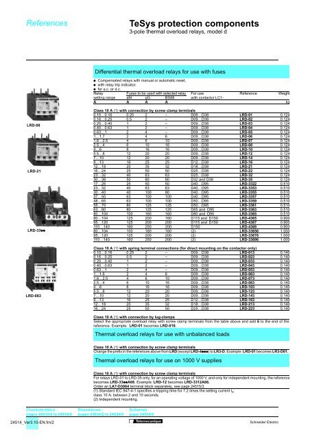
3-pole thermal overload relays, model d<br />
Differential thermal overload relays for use with fuses<br />
/ Compensated relays with manual or automatic reset,<br />
/ with relay trip indicator,<br />
/ for a.c. or d.c.<br />
Relay Fuses to be used with selected relay For use Reference Weight<br />
setting range aM gG BS88 with contactor LC1-<br />
A A A A kg<br />
LRD-08<br />
LRD-21<br />
LRD-33//<br />
LRD-083<br />
Class 10 A (1) with connection by screw clamp terminals<br />
0.10…0.16 0.25 2 – D09…D38 LRD-01 0.124<br />
0.16…0.25 0.5 2 – D09…D38 LRD-02 0.124<br />
0.25…0.40 1 2 – D09…D38 LRD-03 0.124<br />
0.40…0.63 1 2 – D09…D38 LRD-04 0.124<br />
0.63…1 2 4 – D09…D38 LRD-05 0.124<br />
1…1.7 2 4 6 D09…D38 LRD-06 0.124<br />
1.6…2.5 4 6 10 D09…D38 LRD-07 0.124<br />
2.5…4 6 10 16 D09…D38 LRD-08 0.124<br />
4…6 8 16 16 D09…D38 LRD-10 0.124<br />
5.5…8 12 20 20 D09…D38 LRD-12 0.124<br />
7…10 12 20 20 D09…D38 LRD-14 0.124<br />
9…13 16 25 25 D12…D38 LRD-16 0.124<br />
12…18 20 35 32 D18…D38 LRD-21 0.124<br />
16…24 25 50 50 D25…D38 LRD-22 0.124<br />
23…32 40 63 63 D25…D38 LRD-32 0.124<br />
30…38 50 80 80 D32 and D38 LRD-35 0.124<br />
17…25 25 50 50 D40…D95 LRD-3322 0.510<br />
23…32 40 63 63 D40…D95 LRD-3353 0.510<br />
30…40 40 100 80 D40…D95 LRD-3355 0.510<br />
37…50 63 100 100 D40…D95 LRD-3357 0.510<br />
48…65 63 100 100 D50…D95 LRD-3359 0.510<br />
55…70 80 125 125 D50…D95 LRD-3361 0.510<br />
63…80 80 125 125 D65 and D95 LRD-3363 0.510<br />
80…104 100 160 160 D80 and D95 LRD-3365 0.510<br />
80…104 125 200 160 D115 and D150 LRD-4365 0.900<br />
95…120 125 200 200 D115 and D150 LRD-4367 0.900<br />
110…140 160 250 200 D150 LRD-4369 0.900<br />
80…104 100 160 160 (2) LRD-33656 1.000<br />
95…120 125 200 200 (2) LRD-33676 1.000<br />
110…140 160 250 200 (2) LRD-33696 1.000<br />
Class 10 A (1) with spring terminal connections (for direct mounting on the contactor only)<br />
0.10…0.16 0.25 2 – D09…D38 LRD-013 0.140<br />
0.16…0.25 0.5 2 – D09…D38 LRD-023 0.140<br />
0.25…0.40 1 2 – D09…D38 LRD-033 0.140<br />
0.40…0.63 1 2 – D09…D38 LRD-043 0.140<br />
0.63…1 2 4 – D09…D38 LRD-053 0.140<br />
1…1.6 2 4 6 D09…D38 LRD-063 0.140<br />
1.6…2.5 4 6 10 D09…D38 LRD-073 0.140<br />
2.5…4 6 10 16 D09…D38 LRD-083 0.140<br />
4…6 8 16 16 D09…D38 LRD-103 0.140<br />
5.5…8 12 20 20 D09…D38 LRD-123 0.140<br />
7…10 12 20 20 D09…D38 LRD-143 0.140<br />
9…13 16 25 25 D12…D38 LRD-163 0.140<br />
12…18 20 35 32 D18…D38 LRD-213 0.140<br />
16…24 25 50 50 D25…D38 LRD-223 0.140<br />
Class 10 A (1) with connection by lug-clamps<br />
Select the appropriate overload relay with screw clamp terminals from the table above and add 6 to the end of the<br />
reference. Example: LRD-01 becomes LRD-016.<br />
Thermal overload relays for use with unbalanced loads<br />
Class 10 A (1) with connection by screw clamp terminals<br />
Change the prefix in the references above from LRD (except LRD-4///) to LR3-D. Example: LRD-01 becomes LR3-D01.<br />
Thermal overload relays for use on 1000 V supplies<br />
Class 10 A (1) with connection by screw clamp terminals<br />
For relays LRD-01 to LRD-35 only, for an operating voltage of 1000 V, and only for independent mounting, the reference<br />
becomes LRD-33//A66. Example: LRD-12 becomes LRD-3312A66.<br />
Order an LA7-D3064 terminal block separately, see page 24515/3.<br />
(1) Standard IEC 947-4-1 specifies a tripping time for 7.2 times the setting current I R<br />
:<br />
class 10 A: between 2 and 10 seconds.<br />
(2) Independent mounting.<br />
Characteristics :<br />
pages 24516/2 to 24516/5<br />
24514_Ver3.10-EN.fm/2<br />
Dimensions :<br />
pages 24534/2 to 24534/4<br />
Schemes :<br />
page 24534/5<br />
Schneider Electric
References<br />
<strong>TeSys</strong> <strong>protection</strong> <strong>components</strong><br />
6<br />
3-pole thermal overload relays, model d<br />
Differential thermal overload relays for use with fuses<br />
/ Compensated relays with manual or automatic reset,<br />
/ with relay trip indicator,<br />
/ for a.c. or d.c.<br />
/ LR2-D1508 to 2553: independent mounting<br />
- either by ordering a terminal block LA7-D1064 or LA7-D2064, see page 24515/3,<br />
- or by ordering the the relay pre-assembled; in this case add the suffix LA7 to the reference.<br />
Example: LR2-D1508 becomes LR2-D1508LA7.<br />
Relay Fuses to be used For use Reference Weight<br />
setting with the selected relay with contactor<br />
range aM gG BS88 LC1<br />
A A A A kg<br />
Class 20 (1) for connection by screw clamp terminals<br />
LRZ-D15//<br />
2.5…4 6 10 16 D09…D32 LR2-D1508 0.190<br />
4…6 8 16 16 D09…D32 LR2-D1510 0.190<br />
5.5…8 12 20 20 D09…D32 LR2-D1512 0.190<br />
7…10 16 20 25 D09…D32 LR2-D1514 0.190<br />
9…13 16 25 25 D12…D32 LR2-D1516 0.190<br />
12…18 25 35 40 D18…D32 LR2-D1521 0.190<br />
17…25 32 50 50 D25 and D32 LR2-D1522 0.190<br />
23…32 40 63 63 D25 and D32 LR2-D2553 0.345<br />
17…25 32 50 50 D40…D95 LR2-D3522 0.535<br />
23…32 40 63 63 D40…D95 LR2-D3553 0.535<br />
30…40 50 100 80 D40…D95 LR2-D3555 0.535<br />
37…50 63 100 100 D50…D95 LR2-D3557 0.535<br />
48…65 80 125 100 D50…D95 LR2-D3559 0.535<br />
55…70 100 125 125 D65…D95 LR2-D3561 0.535<br />
63…80 100 160 125 D80 and D95 LR2-D3563 0.535<br />
Electronic differential thermal overload relays for use with fuses<br />
LRZ-D25//<br />
/ Compensated relays,<br />
/ with relay trip indicator,<br />
/ for a.c. or d.c.,<br />
/ for direct mounting on contactor or independent mounting (2).<br />
Relay Fuses to be used For direct mounting Reference Weight<br />
setting with selected relay beneath contactor<br />
range aM gG LC1<br />
A A A kg<br />
Class 10 or 10A (1) with connection using bars or connectors<br />
60…100 100 160 D115 and D150 LR9-D5367 0.885<br />
90…150 160 250 D115 and D150 LR9-D5369 0.885<br />
Class 20 (3) with connection using bars or connectors<br />
60…100 125 160 D115 and D150 LR9-D5567 0.885<br />
90…150 200 250 D115 and D150 LR9-D5569 0.885<br />
Electronic thermal overload relays for use with balanced or unbalanced loads<br />
LRZ-D35//<br />
/ Compensated relays,<br />
/ with separate outputs for alarm and tripping.<br />
Relay Fuses to be used For direct mounting Reference Weight<br />
setting with the selected relay beneath contactor<br />
range aM gG LC1<br />
A A A kg<br />
Class 10 or 20 (1) selectable with connection using bars or connectors<br />
60…100 100 160 D115 and D150 LR9-D67 0.900<br />
90…150 160 250 D115 and D150 LR9-D69 0.900<br />
(1) Standard IEC 947-4-1 specifies a tripping time for 7.2 times the setting current I R<br />
class 10: between 4 and 10 seconds,<br />
class 10 A: between 2 and 10 seconds,<br />
class 20: between 6 and 20 seconds.<br />
(2) Power terminals can be protected against direct finger contact by the addition of shrouds and/or insulated terminal<br />
blocks, to be ordered separately (see page 24511/8).<br />
Characteristics :<br />
pages 24516/2 to 24516/5<br />
Other versions<br />
Dimensions :<br />
pages 24534/2 to 24534/4<br />
Thermal overload relays for resistive circuits in category AC-1.<br />
Please consult your Regional Sales Office.<br />
Schemes :<br />
page 24534/5<br />
Schneider Electric<br />
24514_Ver3.10-EN.fm/3
24515_Ver3.20-EN.fm/2<br />
Schneider Electric
References<br />
<strong>TeSys</strong> <strong>protection</strong> <strong>components</strong><br />
6<br />
3-pole thermal overload relays, model d<br />
Accessories (to be ordered separately)<br />
Description For Sold in Unit Weight<br />
use on lots of reference kg<br />
Pre-wiring kit allowing direct LC1-D09…D18 10 LAD-7C1 0.002<br />
connection of the N/C contact<br />
of relay LRD-01…35 or LC1-D25…D38 10 LAD-7C2 0.003<br />
LR3-D01…D35 to the contactor<br />
Terminal blocks (1) LRD-01…35 and LR3-D01…D35 1 LAD-7B10 0.100<br />
for clip-on mounting on 35 mm LR2-D15// 1 LA7-D1064 0.100<br />
rail (AM1-DP200) or screw LR2-D25// 1 LA7-D2064 0.120<br />
fixing; for fixing centres, see LRD-3///, LR3-D3///, 1 LA7-D3064 (2) 0.370<br />
pages 24534/2 to 24534/4 LR2-D35//<br />
Terminal block adapter LRD-3///, LR3-D3///, 1 LA7-D3058 0.080<br />
for mounting a relay<br />
LRD-35//<br />
beneath an LC1-D115 or D150<br />
contactor<br />
Mounting plates (3) LRD-01…35, LR3-D01…D35. 10 DX1-AP25 0.065<br />
for screw fixing<br />
LR2-D15//<br />
on 110 mm centres LR2-D25// 10 DX1-AP26 0.082<br />
LRD-3///, LR3-D3/// 1 LA7-D902 0.130<br />
LR2-D35//<br />
LAD-7C/<br />
Marker holder All relays except LRD-01…35 100 LA7-D903 0.001<br />
snap in and LR3-D01…D35 (4)<br />
Bag of 400 labels – 1 LA9-D91 0.001<br />
(blank, self-adhesive, 7 x 16 mm)<br />
Stop button locking device All relays except LRD-01…35. 10 LA7-D901 0.005<br />
LR3-D01…D35 and LR9-D<br />
Remote stop or electrical LRD-01…35 and LR3-D01…D35 1 LAD-703/ (6) 0.090<br />
reset device (5)<br />
Remote tripping or electrical All relays except LRD-01…35 1 LA7-D03/(6) 0.090<br />
reset device (5)<br />
and LR3-D01…D35<br />
Block of insulated terminals LR9-D 2 LA9-F103 0.560<br />
Remote control<br />
“Reset” function<br />
By flexible cable LRD-01…35 and LR3-D01…D35 1 LAD-7305 0.075<br />
(length = 0.5 m) All relays except LRD-01…35 1 LA7-D305 0.075<br />
and LR3-D01…D35<br />
LAD-7B10<br />
“Stop” and/or “Reset” functions<br />
The terminal <strong>protection</strong> shroud must be removed and the following 3 products must be ordered separately.<br />
Adapter All relays except LRD-01…35 1 LA7-D1020 0.005<br />
for door interlock mechanism and LR3-D01…D35<br />
Illustrations :<br />
page 24515/2<br />
Schneider Electric<br />
Operating head Stop All relays 1 XB5-AL84101 0.027<br />
for spring return pushbutton Reset All relays 1 XB5-AA86102 0.027<br />
(1) Terminal blocks are supplied with terminals protected against direct finger contact and screws in the open, “readyto-tighten”<br />
position.<br />
(2) To order a terminal block for connection by lugs, the reference becomes LA7-D30646.<br />
(3) Do not forget to order the terminal block corresponding to the type of relay.<br />
(4) For LRD-01…35, see page 24511/9.<br />
(5) The time for which the coil of remote tripping or electrical resetting device LA7-D03 or LAD-703 can remain energised<br />
depends on its rest time: 1 s pulse duration with 9 s rest time; 5 s pulse duration with 30 s rest time; 10 s pulse duration<br />
with 90 s rest time; maximum pulse duration of 20 s with a rest time of 300 s. Minimum pulse time: 200 ms.<br />
(6) Reference to be completed by adding the code indicating control circuit voltage.<br />
Standard control circuit voltages (for other voltages, please consult your Regional Sales Office)<br />
Volts 12 24 48 96 110 220/230 380/400 415/440<br />
50/60 Hz – B E – F M Q N<br />
Consumption, inrush and sealed: < 100 VA<br />
$ J B E DD F M – –<br />
Consumption, inrush and sealed: < 100 W.<br />
Dimensions :<br />
pages 24534/2 to 24534/4<br />
24515_Ver3.20-EN.fm/3
Description,<br />
characteristics<br />
<strong>TeSys</strong> <strong>protection</strong> <strong>components</strong><br />
6<br />
3-pole thermal overload relays, model d<br />
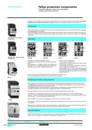
Description<br />
Model d 3-pole thermal overload relays are designed to protect a.c. circuits and motors against overloads, phase failure,<br />
long starting times and prolonged stalling of the motor.<br />
LRD-01…35<br />
5<br />
3<br />
3,5 0 1<br />
4<br />
RESET<br />
STOP<br />
1<br />
6<br />
2 & 5<br />
4<br />
3<br />
2<br />
6<br />
LRD-3322…4369, LR2-D<br />
7<br />
NO<br />
NC<br />
98 97 95 96<br />
1 Adjustment dial Ir<br />
2 Test button<br />
Operation of the Test button allows:<br />
- checking of control circuit wiring,<br />
- simulation of relay tripping (actuates both the N/O and N/C contacts).<br />
3 Stop button. Actuates the N/C contact; does not affect the N/O contact.<br />
4 Reset button<br />
5 Trip indicator<br />
6 Setting locked by sealing the cover.<br />
7 Selector for manual or automatic reset. Relays LRD-01 to 35 are supplied with the selector in the manual position,<br />
protected by a cover. Deliberate action is required to move it to the automatic position.<br />
41<br />
37<br />
TEST<br />
46<br />
50<br />
A<br />
M<br />
R<br />
A E<br />
S<br />
E<br />
T<br />
1<br />
5<br />
3<br />
4<br />
Environment<br />
Conforming to standards IEC 947-1, IEC 947-4-1, NF C 63-650, VDE 0660,<br />
BS 4941<br />
Product certifications<br />
CSA, UL, Sichere Trennung, PTB except LAD-4:<br />
UL, CSA.<br />
Degree of <strong>protection</strong> Conforming to VDE 0106 Protection against direct finger contact IP 2X<br />
Protective treatment Conforming to IEC 68 “TH”<br />
Ambient air temperature Storage °C - 60…+ 70<br />
around the device Normal operation, without derating (IEC 947-4-1) °C - 20…+ 60<br />
Minimum and maximum operating temperatures °C - 40…+ 70<br />
(with derating)<br />
Operating positions In relation to normal, vertical mounting plane Any position<br />
without derating<br />
Shock resistance Permissible acceleration conforming to IEC 68-2-7 15 gn - 11 ms<br />
Vibration resistance Permissible acceleration conforming to IEC 68-2-6 6 gn<br />
Dielectric strength at 50 Hz Conforming to IEC 255-5 kV 6<br />
Impulse withstand voltage Conforming to IEC 801-5 kV 6<br />
Auxiliary contact characteristics<br />
Conventional thermal current A 5<br />
Maximum consumption a.c. supply V 24 48 110 220 380 600<br />
of operating coils VA 100 200 400 600 600 600<br />
of controlled contactors<br />
(Occasional operating d.c. supply V 24 48 110 220 440 –<br />
cycles of contact 95-96) W 100 100 50 45 25 –<br />
Short-circuit <strong>protection</strong> By gG or BS fuse. Max. rating or by GB2 circuit-breaker A 5<br />
Connection to screw clamp terminals<br />
Min/max c.s.a.<br />
Flexible cable without cable end 1 or 2 conductors mm2 1/2.5<br />
Flexible cable with cable end 1 or 2 conductors mm2 1/2.5<br />
Solid cable without cable end 1 or 2 conductors mm2 1/2.5<br />
Tightening torque N.m 1.7<br />
Connection to spring terminals<br />
Min/max c.s.a.<br />
Flexible cable without cable end 1 or 2 conductors mm2 1/2.5<br />
Solid cable without cable end 1 or 2 conductors mm2 1/2.5<br />
References:<br />
pages 24514/2 and<br />
24514/3<br />
Dimensions:<br />
pages 24534/2 to 24534/<br />
4<br />
Schemes:<br />
page 24534/5<br />
24516_Ver2.30-EN.fm/2<br />
Schneider Electric
Characteristics<br />
<strong>TeSys</strong> <strong>protection</strong> <strong>components</strong><br />
6<br />
3-pole thermal overload relays, model d<br />
Electrical characteristics of power circuit<br />
Relay type<br />
LRD-<br />
01 to 16<br />
LR3-<br />
D01 to D16<br />
LR2-<br />
D15//<br />
LRD-<br />
21 to 35<br />
LR3-<br />
D21 to D35<br />
LR2-<br />
D25//<br />
LRD-<br />
3322 to<br />
33696<br />
LR3-<br />
D3322 to<br />
D33696<br />
LR2-<br />
D35//<br />
LRD-<br />
4365 to<br />
4369<br />
Tripping class To UL 508, IEC 947-4-1 10 A 20 10 A 20 10 A 20 10 A<br />
V<br />
Rated insulation voltage (Ui) Conforming to IEC 947-4-1<br />
690 690 1000 1000<br />
Conforming to UL, CSA V 600 600 600 600 except<br />
LRD-4369<br />
Rated impulse withstand<br />
voltage (Uimp) kV 6 6 6 6<br />
Frequency limits Of the operational current Hz 0…400 0…400 0…400 0…400<br />
Setting range Depending on model A 0.1…13 12…38 17…104 80…140<br />
Connection to screw clamp terminals<br />
Min/max c.s.a.<br />
Flexible cable without cable end 1 conductor mm2 1.5/10 1.5/10 4/35 4/50<br />
Flexible cable with cable end 1 conductor mm2 1/4 1/6 except<br />
LRD-21: 1/4<br />
Solid cable without cable end 1 conductor mm2 1/6 1.5/10 except<br />
LRD-21: 1/6<br />
4/35 4/35<br />
4/35 4/50<br />
Tightening torque N.m 1.7 1.85 2.5 9 9<br />
Connection to spring terminals<br />
Min/max c.s.a.<br />
Flexible cable without cable end 1 conductor mm2 1.5/4 – 1.5/4 – – – –<br />
Solid cable without cable end 1 conductor mm 2 1.5/4 – 1.5/4 – – – –<br />
Operating characteristics<br />
Temperature compensation °C - 20…+ 60 - 30…+ 60- - 30…+ 60 - 20…+ 60<br />
Tripping threshold Conforming to IEC 947-4-1 A 1.14 ± 0.06 In<br />
Sensitivity to phase failure Conforming to IEC 947-4-1 Tripping current 30 % of In on one phase, the others at In<br />
Tripping curves<br />
Average operating time<br />
related to multiples of the<br />
current setting<br />
Seconds Minutes<br />
Hours<br />
2<br />
1<br />
40<br />
20<br />
10<br />
4<br />
2<br />
1<br />
40<br />
20<br />
10<br />
Time<br />
class 10 A<br />
4<br />
1<br />
2<br />
2<br />
3<br />
1<br />
0,8<br />
0,8 1 2 4 6 10 17 20<br />
x current setting (Ir)<br />
Seconds Minutes Hours<br />
2<br />
1<br />
40<br />
20<br />
10<br />
1 Balanced operation, 3-phase, from cold state.<br />
2 Balanced operation, 2-phase, from cold state.<br />
3 Balanced operation, 3-phase, after a long period at the set current (hot state).<br />
Time<br />
class 20<br />
4<br />
2<br />
1<br />
40<br />
20<br />
10<br />
1<br />
4<br />
2<br />
3<br />
2<br />
1<br />
0,8<br />
0,8 1 2 4 6 10 17 20<br />
x current setting (Ir)<br />
References:<br />
pages 24514/2 and<br />
24514/3<br />
Dimensions:<br />
pages 24534/2 to 24534/<br />
4<br />
Schemes:<br />
page 24534/5<br />
Schneider Electric<br />
24516_Ver2.30-EN.fm/3
Description,<br />
characteristics<br />
<strong>TeSys</strong> <strong>protection</strong> <strong>components</strong><br />
6<br />
3-pole electronic thermal overload relays LR9-D<br />
Description<br />
LR9-D electronic thermal overload relays are designed for use with contactors LC1-D115 and D150.<br />
In addition to the <strong>protection</strong> provided by model d thermal overload relays (see page 24516/2) they offer the following<br />
special features:<br />
/ Protection against phase imbalance.<br />
/ Choice of starting class.<br />
/ Protection of unbalanced circuits.<br />
/ Protection of single-phase circuits.<br />
/ Alarm function to avoid tripping by load shedding.<br />
1 Setting dial Ir<br />
2 Test button<br />
3 Stop button<br />
4 Reset button<br />
5 Trip indication<br />
6 Setting locked by sealing the cover<br />
7 Class 10/class 20 selector<br />
8 Selector for balanced load /<br />
unbalanced load<br />
LR9-D5367…D5569<br />
Ir(A)<br />
107 127<br />
90 150<br />
NO 98 97<br />
NC<br />
95 96<br />
1<br />
2<br />
5<br />
4<br />
3<br />
6<br />
LR9-D67 and D69<br />
Class Load<br />
Ir(A) 20<br />
107 127<br />
10<br />
+ 24 V - / 103 104<br />
90 150<br />
Alarm<br />
NO 98 97<br />
NC<br />
95 96<br />
7<br />
8<br />
2<br />
5<br />
4<br />
3<br />
1<br />
6<br />
Environment<br />
Conforming to standards IEC 947-4-1, 255-8, 255-17, VDE 0660 and EN 60947-4-1<br />
Product certifications UL 508 , CSA 22-2<br />
Degree of <strong>protection</strong> Conforming to IEC 529 and VDE 0106 IP 20 on front face<br />
with protective covers LA9-D11570/ or D11560/<br />
Protective treatment Standard version "TH"<br />
Ambient air temperature Storage °C - 40…+ 85<br />
around the device<br />
(conforming to IEC 255-8)<br />
Normal operation °C - 20…+ 55 (1)<br />
Maximum operating altitude Without derating m 2000<br />
Operating positions<br />
In relation to normal, vertical<br />
without derating<br />
mounting plane<br />
Any position<br />
Shock resistance<br />
Permissible acceleration<br />
13 gn - 11 ms<br />
conforming to IEC 68-2-27<br />
Vibration resistance<br />
Permissible acceleration<br />
conforming to IEC 68-2-6<br />
2 gn - 5 to 300 Hz<br />
Dielectric strength at 50 Hz Conforming to IEC 255-5 kV 6<br />
Impulse withstand voltage Conforming to IEC 1000-4-5 kV 6<br />
Resistance to electrostatic discharge Conforming to IEC 1000-4-2 kV 8<br />
Resistance to radio-frequency Conforming to IEC 1000-4-3<br />
conducted disturbances<br />
and NF C 46-022<br />
V/m 10<br />
Resistance to fast transient currents Conforming to IEC 1000-4-4 kV 2<br />
Electromagnetic compatibility Draft EN 50081-1 and 2, EN 50082-2 Meets requirements<br />
Electrical characteristics of auxiliary contacts<br />
Conventional thermal current A 5<br />
Maximum consumption a.c. supply V 24 48 110 220 380 600<br />
of operating coils VA 100 200 400 600 600 600<br />
of controlled contactors<br />
(Occasional operating cycles<br />
d.c. supply V 24 48 110 220 440 –<br />
of contact 95-96) W 100 100 50 45 25 –<br />
Short-circuit <strong>protection</strong><br />
By gG or BS fuse<br />
or by GB2 circuit-breaker<br />
A 5<br />
Cabling 1 or 2 conductors mm2 Minimum c.s.a.: 1/maximum c.s.a.: 2.5<br />
Flexible cable without cable end Tightening torque N.m 1.2<br />
(1) For operation at 70 °C, please consult your Regional Sales Office.<br />
References:<br />
pages 24514/2 and<br />
24516_Ver2.30-EN.fm/4<br />
24514/3<br />
Dimensions:<br />
pages 24534/2 to 24534/<br />
4<br />
Schemes:<br />
page 24534/5<br />
Schneider Electric
Characteristics<br />
<strong>TeSys</strong> <strong>protection</strong> <strong>components</strong><br />
6<br />
3-pole electronic thermal overload relays LR9-D<br />
Electrical characteristics of power circuit<br />
Relay type<br />
LR9-D<br />
Tripping class Conforming to UL 508, IEC 947-4-1 10 A or 20<br />
Rated insulation voltage (Ui) Conforming to IEC 947-4-1 V 1000<br />
Conforming to UL, CSA V 600<br />
Rated impulse withstand<br />
voltage (Uimp)<br />
kV 8<br />
Frequency limits Of the operational current Hz 50…60. For other frequencies, consult your Regional Sales Office (1)<br />
Setting range Depending on model A 60…150<br />
Power circuit connections Width of terminal lug mm 20<br />
Clamping screw<br />
M8<br />
Tightening torque N.m 18<br />
Operating characteristics<br />
Temperature compensation °C - 20…+ 70<br />
Tripping thresholds To IEC 947-4-1 Alarm A 1.05 ± 0.06 In<br />
Tripping A 1.12 ± 0.06 In<br />
Sensitivity to phase failure Conforming to IEC 947-4-1 Tripping in 4 s ± 20 % in the event of phase failure<br />
Alarm circuit characteristics<br />
Rated supply voltage d.c. supply V 24<br />
Supply voltage limits V 17…32<br />
Current consumption No load mA ≤ 5<br />
Switching capacity mA 0…150<br />
Protection Short-circuit and overload Self-protected<br />
Voltage drop Closed state V ≤ 2.5<br />
Cabling Flexible cable without cable end mm2 0.5…1.5<br />
Tightening torque N.m 0.45<br />
Tripping curve LR9-D<br />
Average operating time<br />
related to multiples of the<br />
current setting<br />
Tripping time in seconds<br />
000<br />
100<br />
10<br />
1<br />
2<br />
1<br />
0 1 1,12 2 3 4 5 6 7 8 9 10 11 12<br />
x the current setting (Ir)<br />
1 Cold state curve<br />
2 Hot state curve<br />
(1) For use of these relays with soft start units or variable speed controllers, please consult your Regional Sales Office.<br />
References:<br />
pages 24514/2 and<br />
24514/3<br />
Dimensions:<br />
pages 24534/2 to 24534/<br />
4<br />
Schemes:<br />
page 24534/5<br />
Schneider Electric<br />
24516_Ver2.30-EN.fm/5
Curves<br />
<strong>TeSys</strong> <strong>protection</strong> <strong>components</strong><br />
Thermal-magnetic motor circuit breakers types GV2-ME<br />
and GV2-P<br />
Thermal-magnetic tripping curves for GV2-ME and GV2-P<br />
Average operating time at 20 °C according to multiples of the setting current<br />
Time (s)<br />
x setting current (Ir)<br />
1 3 poles from cold state<br />
2 2 poles from cold state<br />
3 3 poles from hot state<br />
References :<br />
pages 24508/2 to 24508/4<br />
Dimensions :<br />
pages 24538/2 to 24538/4<br />
Schemes :<br />
page 24538/8<br />
4521 Ver2.00-EN.fm/2 Schneider Electric
Curves (continued)<br />
<strong>TeSys</strong> <strong>protection</strong> <strong>components</strong><br />
Thermal-magnetic motor circuit-breakers types GV2-ME<br />
and GV2-P<br />
Current limitation on short-circuit for GV2-ME and GV2-P<br />
3-phase 400/415 V<br />
Dynamic stress<br />
I peak = f (prospective Isc) at 1.05 Ue = 435 V<br />
Limited peak current (kA)<br />
Prospective Isc (kA)<br />
1 Maximum peak current 7 6-10 A<br />
2 24-32 A 8 4-6.3 A<br />
3 20-25 A 9 2.5-4 A<br />
4 17-23 A 10 1.6-2.5 A<br />
5 13-18 A 11 1-1.6 A<br />
6 9-14 A 12 Limit of rated ultimate breaking capacity on short-circuit<br />
of GV2-ME (14, 18, 23 and 25 A ratings)<br />
References :<br />
pages 24508/2 to 24508/4<br />
Dimensions :<br />
pages 24538/2 to 24538/4<br />
Schemes :<br />
page 24538/8<br />
Schneider Electric<br />
24521 Ver2.00-EN.fm/
Curves (continued)<br />
<strong>TeSys</strong> <strong>protection</strong> <strong>components</strong><br />
Thermal-magnetic motor circuit-breakers types GV2-ME<br />
and GV2-P<br />
Thermal limit on short-circuit for GV2-ME<br />
Thermal limit in KA 2 s in the magnetic operating zone<br />
Sum of I 2 dt = f (prospective Isc) at 1.05 Ue = 435 V<br />
Sum of I 2 dt (kA 2 s)<br />
Prospective Isc (kA)<br />
1 24-32 A 6 6-10 A<br />
2 20-25 A 7 4-6.3 A<br />
3 17-23 A 8 2.5-4 A<br />
4 13-18 A 9 1.6-2.5 A<br />
5 9-14 A 10 1-1.6 A<br />
References :<br />
pages 24508/2 to 24508/4<br />
Dimensions :<br />
pages 24538/2 to 24538/4<br />
Schemes :<br />
page 24538/8<br />
4521 Ver2.00-EN.fm/4 Schneider Electric
Curves (continued)<br />
<strong>TeSys</strong> <strong>protection</strong> <strong>components</strong><br />
Thermal-magnetic motor circuit-breakers types GV2-ME<br />
and GV2-P<br />
Thermal limit on short-circuit for GV2-P<br />
Thermal limit in kA 2 s in the magnetic operating zone<br />
Sum of I 2 dt = f (prospective Isc) at 1.05 Ue = 435 V<br />
Sum of I 2 dt (kA 2 s)<br />
Prospective Isc (kA)<br />
1 24-32 A 6 6-10 A<br />
2 20-25 A 7 4-6.3 A<br />
3 17-23 A 8 2.5-4 A<br />
4 13-18 A 9 1.6-2.5 A<br />
5 9-14 A 10 1-1.6 A<br />
References :<br />
pages 24508/2 to 24508/4<br />
Dimensions :<br />
pages 24538/2 to 24538/4<br />
Schemes :<br />
page 24538/8<br />
Schneider Electric<br />
24521 Ver2.00-EN.fm/
Curves<br />
<strong>TeSys</strong> <strong>protection</strong> <strong>components</strong><br />
Thermal-magnetic motor circuit-breakers type GV3-ME<br />
Thermal-magnetic tripping curves<br />
Average operating time at 20 °C according to multiples of the setting current.<br />
Time (s)<br />
X setting current (Ir)<br />
1 3 poles from cold state, 1.6…16 A rating<br />
2 3 poles from hot state , 1.6…16 A rating<br />
3 3 poles from cold state, 25…80 A rating<br />
4 3 poles from hot state, 25…80 A rating<br />
References :<br />
page 24508/5<br />
Dimensions :<br />
page 24538/5<br />
Schemes :<br />
page 24538/9<br />
4521 Ver2.00-EN.fm/6 Schneider Electric
Curves (continued)<br />
<strong>TeSys</strong> <strong>protection</strong> <strong>components</strong><br />
Thermal-magnetic motor circuit-breakers type GV3-ME<br />
Current limitation on short-circuit<br />
3-phase 400/415 V.<br />
Dynamic stress<br />
I peak = f (prospective Isc) at 1.05 Ue = 435 V<br />
Limited peak current (kA)<br />
Prospective Isc (kA)<br />
1 Maximum peak current 7 6…10 A<br />
2 56…80 A 8 4…6 A<br />
3 40…63 A 9 2.5…4 A<br />
4 25…40 A 10 1.6…2.5 A<br />
5 16…25 A 11 1…1.6 A<br />
6 10…16 A<br />
References :<br />
page 24508/5<br />
Dimensions :<br />
page 24538/5<br />
Schemes :<br />
page 24538/9<br />
Schneider Electric<br />
24521 Ver2.00-EN.fm/
Curves (continued)<br />
<strong>TeSys</strong> <strong>protection</strong> <strong>components</strong><br />
Thermal-magnetic motor circuit-breakers type GV3-ME<br />
Thermal limit on short-circuit<br />
Thermal limit in kA 2 s in the magnetic operating zone<br />
Sum of l 2 dt = f (prospective Isc) at 1.05 Ue = 435 V<br />
Sum of I 2 dt (kA 2 s)<br />
Prospective Isc (kA)<br />
1 56…80 A 6 6…10 A<br />
2 40…63 A 7 4…6 A<br />
3 25…40 A 8 2.5…4 A<br />
4 16…25 A 9 1.6…2.5 A<br />
5 10…16 A<br />
References :<br />
page 24508/5<br />
Dimensions :<br />
page 24538/5<br />
Schemes :<br />
page 24538/9<br />
4521 Ver2.00-EN.fm/8 Schneider Electric
Curves<br />
<strong>TeSys</strong> <strong>protection</strong> <strong>components</strong><br />
Thermal-magnetic motor circuit-breakers type GV7-R<br />
Thermal-magnetic tripping curves for GV7-R<br />
Average operating time at 20 °C according to multiples of the setting current<br />
Time (s)<br />
x setting current (Ir)<br />
1 Curve from cold state<br />
2 Curve from hot state<br />
3 12…14 Ir<br />
In the event of total phase failure, tripping occurs after 4 s ± 20 %<br />
References :<br />
page 24508/6<br />
Dimensions :<br />
pages 24538/5 to 24538/7<br />
Schemes :<br />
page 24538/9<br />
Schneider Electric<br />
24521 Ver2.00-EN.fm/
Curves (continued)<br />
<strong>TeSys</strong> <strong>protection</strong> <strong>components</strong><br />
Thermal-magnetic motor circuit-breakers type GV7-R<br />
Current limitation on short-circuit<br />
3-phase 400/415 V<br />
Dynamic stress<br />
I peak = f (prospective Isc)<br />
For GV7-RE only<br />
Limited peak current (kA)<br />
1 GV7-RE220<br />
2 GV7-RE150<br />
3 GV7-RE100<br />
Prospective Isc (kA)<br />
For GV7-RS only<br />
Limited peak current (kA)<br />
1 GV7-RS220<br />
2 GV7-RS150<br />
3 GV7-RS100<br />
Prospective Isc (kA)<br />
References :<br />
page 24508/6<br />
Dimensions :<br />
pages 24538/5 to 24538/7<br />
Schemes :<br />
page 24538/9<br />
521 Ver2.00-EN.fm/10 Schneider Electric
Curves (continued)<br />
<strong>TeSys</strong> <strong>protection</strong> <strong>components</strong><br />
Thermal-magnetic motor circuit-breakers type GV7-R<br />
Thermal limit on short-circuit<br />
3-phase 400/415 V<br />
Thermal limit<br />
Sum of I 2 dt = f (prospective Isc)<br />
For GV7-RE only<br />
Sum of I 2 dt (A 2 s)<br />
1 GV7-RE220<br />
2 GV7-RE150<br />
3 GV7-RE100<br />
Prospective Isc (kA)<br />
For GV7-RS only<br />
Sum of I 2 dt (A 2 s)<br />
1 GV7-RS220<br />
2 GV7-RS150<br />
3 GV7-RS100<br />
Prospective Isc (kA)<br />
References :<br />
page 24508/6<br />
Dimensions :<br />
pages 24538/5 to 24538/7<br />
Schemes :<br />
page 24538/9<br />
Schneider Electric<br />
24521 Ver2.00-EN.fm/
Curves (continued)<br />
<strong>TeSys</strong> <strong>protection</strong> <strong>components</strong><br />
Thermal-magnetic motor circuit-breakers type GV7-R<br />
Current limitation on short-circuit<br />
3-phase 690 V<br />
Dynamic stress<br />
I peak = f (prospective Isc)<br />
For GV7-RE only<br />
Limited peak current (kA)<br />
1 GV7-RE220<br />
2 GV7-RE150 and<br />
GV7-RE100<br />
Prospective Isc (kA)<br />
For GV7-RS only<br />
Limited peak current (kA)<br />
1 GV7-RS220<br />
2 GV7-RS150 and<br />
GV7-RS100<br />
Prospective Isc (kA)<br />
References :<br />
page 24508/6<br />
Dimensions :<br />
pages 24538/5 to 24538/7<br />
Schemes :<br />
page 24538/9<br />
521 Ver2.00-EN.fm/12 Schneider Electric
Curves (continued)<br />
<strong>TeSys</strong> <strong>protection</strong> <strong>components</strong><br />
Thermal-magnetic motor circuit-breakers type GV7-R<br />
Thermal limit on short-circuit<br />
3-phase 690 V<br />
Thermal limit<br />
Sum of I 2 dt = f (prospective Isc)<br />
For GV7-RE only<br />
Sum of I 2 dt (A 2 s)<br />
1 GV7-RE220<br />
2 GV7-RE150 and<br />
GV7-RS100<br />
Prospective Isc (kA)<br />
For GV7-RS only<br />
Sum of I 2 dt (A 2 s)<br />
1 GV7-RS220<br />
2 GV7-RS150 and<br />
GV7-RS100<br />
Prospective Isc (kA)<br />
References :<br />
page 24508/6<br />
Dimensions :<br />
pages 24538/5 to 24538/7<br />
Schemes :<br />
page 24538/9<br />
Schneider Electric<br />
24521 Ver2.00-EN.fm/
Curves<br />
<strong>TeSys</strong> <strong>protection</strong> <strong>components</strong><br />
Thermal-magnetic motor circuit-breakers type GV2-RT<br />
Thermal-magnetic tripping curves for GV2-RT<br />
Time (s)<br />
1 3 poles from cold state<br />
2 2 poles from cold state<br />
3 3 poles from hot state<br />
References :<br />
page 24508/7<br />
Dimensions :<br />
page 24538/4<br />
Schemes :<br />
page 24538/8<br />
521 Ver2.00-EN.fm/14 Schneider Electric
Curves<br />
<strong>TeSys</strong> <strong>protection</strong> <strong>components</strong><br />
Magnetic motor circuit-breakers types GV2-L and GV2-LE<br />
Tripping curves for GV2-L or LE combined with thermal overload relay LRD or LR2-K<br />
Average operating time at 20°C according to multiples of the setting current<br />
Time (s)<br />
x setting current (Ir)<br />
1 3 poles from cold state<br />
2 2 poles from cold state<br />
3 3 poles from hot state<br />
References :<br />
page 24522/2<br />
Dimensions :<br />
pages 24527/2 to 24527/4<br />
Schemes :<br />
page 24527/5<br />
Schneider Electric<br />
24521 Ver2.00-EN.fm/
Curves (continued)<br />
<strong>TeSys</strong> <strong>protection</strong> <strong>components</strong><br />
Magnetic motor circuit-breakers types GV2-L and GV2-LE<br />
Current limitation on short-circuit<br />
For GV2-L and GV2-LE only<br />
3-phase 400/415 V<br />
Dynamic stress<br />
I peak = f (prospective Isc) at 1.05 Ue = 435 V<br />
Limited peak current (kA)<br />
Prospective Isc (kA)<br />
1 Maximum peak current 6 10 A.<br />
2 32 A 7 6.3 A<br />
3 25 A 8 4 A<br />
4 18 A 9 2.5 A<br />
5 14 A 10 1.6 A<br />
11 Limit of rated ultimate breaking capacity on short-circuit of GV2-LE<br />
(14, 18 and 25 A ratings)<br />
References :<br />
page 24522/2<br />
Dimensions :<br />
pages 24527/2 to 24527/4<br />
Schemes :<br />
page 24527/5<br />
521 Ver2.00-EN.fm/16 Schneider Electric
Curves (continued)<br />
<strong>TeSys</strong> <strong>protection</strong> <strong>components</strong><br />
Magnetic motor circuit-breakers types GV2-L and GV2-LE<br />
Current limitation on short-circuit<br />
For GV2-L and GV2-LE + thermal overload relay LRD or LR2-K<br />
3-phase 400/415 V<br />
Dynamic stress<br />
I peak = f (prospective Isc) at 1.05 Ue = 435 V<br />
Limited peak current (kA)<br />
Prospective Isc (kA)<br />
1 Maximum peak current 6 10 A<br />
2 32 A 7 6.3 A<br />
3 25 A 8 4 A<br />
4 18 A 9 2.5 A<br />
5 14 A 10 1.6 A<br />
11 Limit of rated ultimate breaking capacity on short-circuit<br />
of GV2-LE (14, 18 and 25 A ratings)<br />
References :<br />
page 24522/2<br />
Dimensions :<br />
pages 24527/2 to 24527/4<br />
Schemes :<br />
page 24527/5<br />
Schneider Electric<br />
24521 Ver2.00-EN.fm/
Curves (continued)<br />
<strong>TeSys</strong> <strong>protection</strong> <strong>components</strong><br />
Magnetic motor circuit-breakers types GV2-L and GV2-LE<br />
Thermal limit on short-circuit for GV2-LE only<br />
Thermal limit in kA 2 s in the magnetic operating zone<br />
Sum of I 2 dt = f (prospective Isc) at 1.05 Ue = 435 V<br />
Sum of I 2 dt (kA 2 s)<br />
Prospective Isc (kA)<br />
1 32 A 6 6.3 A<br />
2 25 A 7 4 A<br />
3 18 A 8 2.5 A<br />
4 14 A 9 1.6 A<br />
5 10 A<br />
References :<br />
page 24522/2<br />
Dimensions :<br />
pages 24527/2 to 24527/4<br />
Schemes :<br />
page 24527/5<br />
521 Ver2.00-EN.fm/18 Schneider Electric
Curves (continued)<br />
<strong>TeSys</strong> <strong>protection</strong> <strong>components</strong><br />
Magnetic motor circuit-breakers types GV2-L and GV2-LE<br />
Thermal limit on short-circuit for GV2-L only<br />
Thermal limit in kA 2 s in the magnetic operating zone<br />
Sum of I 2 dt = f (prospective Isc) at 1.05 Ue = 435 V<br />
Sum of I 2 dt (kA 2 s)<br />
1 25 A and 32 A 5 6.3 A<br />
2 18 A 6 4 A<br />
3 14 A 7 2.5 A<br />
4 10 A 8 1.6 A<br />
Prospective Isc (kA)<br />
References :<br />
page 24522/2<br />
Dimensions :<br />
pages 24527/2 to 24527/4<br />
Schemes :<br />
page 24527/5<br />
Schneider Electric<br />
24521 Ver2.00-EN.fm/
Curves (continued)<br />
<strong>TeSys</strong> <strong>protection</strong> <strong>components</strong><br />
Magnetic motor circuit-breakers types GV2-L and GV2-LE<br />
Thermal limit on short-circuit<br />
For GV2-L and GV2-LE + thermal overload relay LRD or LR2-K<br />
Thermal limit in kA 2 s in the magnetic operating zone<br />
Sum of I 2 dt = f (prospective Isc) at 1.05 Ue = 435 V<br />
Sum of I2dt (kA2 s)<br />
Prospective Isc (kA)<br />
1 32 A (GV2-LE32) 7 4 A<br />
2 25 A and 32 A (GV2-L32) 8 2.5 A<br />
3 18 A 9 1.6 A<br />
4 14 A 10 Limit of rated ultimate breaking capacity on short-circuit<br />
5 10 A of GV2-LE (14, 18 and 25 A ratings)<br />
6 6.3 A<br />
References :<br />
page 24522/2<br />
Dimensions :<br />
pages 24527/2 to 24527/4<br />
Schemes :<br />
page 24527/5<br />
521 Ver2.00-EN.fm/20 Schneider Electric
Curves<br />
<strong>TeSys</strong> <strong>protection</strong> <strong>components</strong><br />
Magnetic motor circuit-breaker type GK3<br />
Tripping curves for GK3 combined with thermal overload relay LRD-33<br />
Average operating time at 20 °C without prior current flow.<br />
Time (s)<br />
x setting current (Ir)<br />
1 3 poles from cold state<br />
2 2 poles from cold state<br />
3 3 poles from hot state<br />
A Thermal overload relay <strong>protection</strong> zone<br />
B GK3 <strong>protection</strong> zone<br />
References :<br />
page 24522/3<br />
Dimensions :<br />
page 24527/4<br />
Schemes :<br />
page 24527/5<br />
Schneider Electric<br />
24521 Ver2.00-EN.fm/2
Curves (continued)<br />
<strong>TeSys</strong> <strong>protection</strong> <strong>components</strong><br />
Magnetic motor circuit-breaker type GK3<br />
Current limitation on short-circuit for GK3 only<br />
3-phase 400/415 V<br />
Dynamic stress<br />
I peak = f (prospective Isc) at 1.05 Ue = 435 V<br />
Limited peak current (kA)<br />
1 Maximum peak current<br />
2 80 A<br />
3 65 A<br />
4 40 A<br />
Prospective Isc (kA)<br />
References :<br />
page 24522/3<br />
Dimensions :<br />
page 24527/4<br />
Schemes :<br />
page 24527/5<br />
521 Ver2.00-EN.fm/22 Schneider Electric
Curves (continued)<br />
<strong>TeSys</strong> <strong>protection</strong> <strong>components</strong><br />
Magnetic motor circuit-breaker type GK3<br />
Thermal limit on short-circuit for GK3 only<br />
Thermal limit in A 2 s<br />
Sum of I 2 dt = f (prospective Isc) at 1.05 Ue = 435 V<br />
Sum of I 2 dt (A 2 s)<br />
Prospective Isc (kA)<br />
1 80 A<br />
2 65 A<br />
3 40 A<br />
References :<br />
page 24522/3<br />
Dimensions :<br />
page 24527/4<br />
Schemes :<br />
page 24527/5<br />
Schneider Electric<br />
24521 Ver2.00-EN.fm/2
Selection guide<br />
<strong>TeSys</strong> contactors<br />
For utilisation category AC-3<br />
Operational current and power conforming to IEC (θ ≤ 60 °C)<br />
Contactor LC1- LC1- LC1- LC1- LC1- LC1- LC1- LC1- LC1- LC1- LC1-<br />
size LP1- LP1- LP1-<br />
K06 K09 K12 K16 D09 D12 D18 D25 D32 D38 D40<br />
Max. operational ≤ 440 V A 6 9 12 16 9 12 18 25 32 38 40<br />
current in AC-3<br />
Rated 220/240 V kW 1.5 2.2 3 3 2.2 3 4 5.5 7.5 9 11<br />
operational<br />
power P<br />
(standard 380/400 V kW 2.2 4 5.5 7.5 4 5.5 7.5 11 15 18.5 18.5<br />
motor power<br />
ratings)<br />
415 V kW 2.2 4 5.5 7.5 4 5.5 9 11 15 18.5 22<br />
440 V kW 3 4 5.5 7.5 4 5.5 9 11 15 18.5 22<br />
500 V kW 3 4 4 5.5 5.5 7.5 10 15 18.5 18.5 22<br />
660/690 V kW 3 4 4 4 5.5 7.5 10 15 18.5 18.5 30<br />
1000 V kW – – – – – – – – – – 22<br />
Maximum operating rate in operating cycles/hour (1)<br />
On-load Operational LC1- LC1- LC1- LC1- LC1- LC1- LC1-<br />
factor<br />
power<br />
D09 D12 D18 D25 D32 D38 D40<br />
≤ 85% P – – – – 1200 1200 1200 1200 1000 1000 1000<br />
0.5 P – – – – 3000 3000 2500 2500 2500 2500 2500<br />
≤ 25 % P – – – – 1800 1800 1800 1800 1200 1200 1200<br />
Operational current and power conforming to UL, CSA (θ ≤ 60 °C)<br />
Contactor LC1- LC1- LC1- LC1- LC1- LC1- LC1- LC1- LC1- LC1-<br />
size LP1- LP1- LP1-<br />
K06 K09 K12 D09 D12 D18 D25 D32 D38 D40<br />
Max. operational ≤ 440 V A 6 9 12 9 12 18 25 32 – 40<br />
current in AC-3<br />
Rated 200/208 V HP 1.5 2 3 2 3 5 7.5 10 – 10<br />
operational<br />
power P<br />
(standard 230/240 V HP 1.5 3 3 2 3 5 7.5 10 – 10<br />
motor power<br />
ratings)<br />
60 Hz 460/480 V HP 3 5 7.5 5 7.5 10 15 20 – 30<br />
575/600 V HP 3 5 10 7.5 10 15 20 25 – 30<br />
(1) Depending on the operational power and the on-load factor (θ ≤ 60 °C).<br />
Characteristics :<br />
pages 24505/2 to 24505/7<br />
2<br />
References :<br />
pages 24501/2 to 24502/3<br />
Dimensions, schemes :<br />
pages 24531/2 to 24532/3
LC1- LC1- LC1- LC1- LC1- LC1- LC1- LC1- LC1- LC1- LC1- LC1- LC1- LC1- LC1- LC1- LC1- LC1- LC1-<br />
D50 D65 D80 D95 D115 D150 F185 F225 F265 F330 F400 F500 F630 F780 F800 BL BM BP BR<br />
50 65 80 95 115 150 185 225 265 330 400 500 630 780 800 750 1000 1500 1800<br />
15 18.5 22 25 30 40 55 63 75 100 110 147 200 220 250 220 280 425 500<br />
22 30 37 45 55 75 90 110 132 160 200 250 335 400 450 400 500 750 900<br />
25 37 45 45 59 80 100 110 140 180 220 280 375 425 450 425 530 800 900<br />
30 37 45 45 59 80 100 110 140 200 250 295 400 425 450 450 560 800 900<br />
30 37 55 55 75 90 110 129 160 200 257 355 400 450 450 500 600 750 900<br />
33 37 45 45 80 100 110 129 160 220 280 335 450 475 475 560 670 750 900<br />
30 37 45 45 65 75 100 100 147 160 185 335 450 450 450 530 530 670 750<br />
LC1- LC1- LC1- LC1- LC1- LC1- LC1- LC1- LC1- LC1- LC1- LC1- LC1- LC1- LC1- LC1- LC1- LC1- LC1-<br />
D50 D65 D80 D95 D115 D150 F185 F225 F265 F330 F400 F500 F630 F780 F800 BL BM BP BR<br />
1000 1000 750 750 750 750 750 750 750 750 500 500 500 500 500 120 120 120 120<br />
2500 2500 2000 2000 2000 1200 2000 2000 2000 2000 1200 1200 1200 1200 600 120 120 120 120<br />
1200 1200 1200 1200 1200 1200 1200 1200 1200 1200 1200 1200 1200 600 600 120 120 120 120<br />
LC1- LC1- LC1- LC1- LC1- LC1- LC1- LC1- LC1- LC1- LC1- LC1- LC1- LC1- LC1-<br />
D50 D65 D80 D95 D115 D150 F185 F225 F265 F330 F400 F500 F630 F780 F800<br />
50 65 80 95 115 150 185 225 265 330 400 500 630 780 800<br />
15 20 30 30 30 40 50 60 60 75 100 150 250 – 350<br />
15 20 30 30 40 50 60 75 75 100 125 200 300 450 400<br />
40 50 60 60 75 100 125 150 150 200 250 400 600 900 900<br />
40 50 60 60 100 125 150 150 200 250 300 500 800 – 900
Selection guide according<br />
to required electrical<br />
durability<br />
<strong>TeSys</strong> contactors<br />
For utilisation category AC-3<br />
Use in category AC-3 (Ue ≤ 440 V)<br />
Control of 3-phase<br />
asynchronous motors<br />
with breaking whilst<br />
running.<br />
The current broken (Ic)<br />
in category AC-3 is<br />
equal to the rated<br />
operational current (Ie)<br />
of the motor.<br />
Millions of operating cycles<br />
Current broken in A<br />
Operational power in kW-50 Hz<br />
Example<br />
Asynchronous motor with P = 5.5 kW -Ue =400 V-Ie =11 A - Ic = Ie =11 A<br />
or asynchronous motor with P = 5.5 kW -Ue = 415 V-Ie =11 A-Ic = Ie = 11 A<br />
3 million operating cycles required.<br />
The above selection curves show the contactor rating needed: LC1-D18.<br />
Use in category AC-3 (Ue =660/690 V) (1)<br />
Control of 3-phase<br />
asynchronous motors<br />
with breaking whilst<br />
running.<br />
The current broken (Ic)<br />
in category AC-3 is<br />
equal to the rated<br />
operational current (Ie)<br />
of the motor.<br />
Millions of operating cycles<br />
Current broken in A<br />
(1) For Ue = 1000 V use the 660/690 V curves, but do not exceed the operational current at the operational power<br />
indicated for 1000 V.<br />
Characteristics :<br />
pages 24505/2 to 24505/7<br />
4<br />
References :<br />
pages 24501/2 to 24502/3<br />
Dimensions, schemes :<br />
pages 24531/2 to 24532/3
Selection guide according<br />
to required electrical<br />
durability (continued)<br />
<strong>TeSys</strong> contactors<br />
For utilisation category AC-3<br />
Use in category AC-3 (Ue ≤ 440 V)<br />
Control of 3-phase<br />
asynchronous motors<br />
with breaking whilst<br />
running.<br />
The current broken (Ic)<br />
in category AC-3 is<br />
equal to the rated<br />
operational current (Ie)<br />
of the motor.<br />
Millions of operating cycles<br />
Current broken in A<br />
Operational power in kW-50 Hz<br />
Example<br />
Asynchronous motor with P = 132 kW -Ue = 380 V-Ie = 245 A - Ic = Ie = 245 A<br />
or asynchronous motor with P = 132 kW -Ue = 415 V-Ie = 240 A - Ic = Ie = 240 A<br />
1.5 million operating cycles required.<br />
The above selection curves show the contactor rating needed: LC1-F330.<br />
(1) The dotted lines are only applicable to contactors LC1-BL.<br />
Use in category AC-3 (Ue =660/690 V)<br />
Control of 3-phase<br />
asynchronous motors<br />
with breaking whilst<br />
running.<br />
The current broken (Ic)<br />
in category AC-3 is<br />
equal to the rated<br />
operational current (Ie)<br />
of the motor.<br />
Millions of operating cycles<br />
Current broken in A<br />
Example<br />
Asynchronous motor with P = 132 kW - Ue = 660 V - Ie = 140 A - Ic = Ie = 140 A<br />
1.5 million operating cycles required.<br />
The above selection curves show the contactor rating needed: LC1-F330.<br />
Characteristics :<br />
pages 24505/2 to 24505/7<br />
(1) The dotted lines are only applicable to contactors LC1-BL.<br />
References :<br />
pages 24501/2 to 24502/3<br />
Dimensions, schemes :<br />
pages 24531/2 to 24532/3
Selection<br />
<strong>TeSys</strong> contactors<br />
For utilisation category AC-1<br />
Maximum operational current (open-mounted device)<br />
Contactor<br />
LC1- LC1- LC1- LC1- LC1- LC1- LC1- LC1- LC1- LC1- LC1-<br />
size LP1- LP1- LP1-<br />
K09 K12 D09 D12 D18 D25 D32 D38 D40<br />
DT20 DT25 DT32 DT40 DT60<br />
Maximum operating rate<br />
in operating cycles/hour 600 600 600 600 600 600 600 600 600 600 600<br />
Connections/ cable c.s.a. mm 2 4 4 4 4 4 6 6 10 16 10 16<br />
cabling conforming<br />
to IEC 947-1 bar size mm – – – – – – – – – – –<br />
Operational current<br />
in AC-1 in A, ≤ 40 °C A 20 20 25 20 25 32 40 50 60 50 60<br />
according to the<br />
ambient temperat- ≤ 60 °C A 20 20 25 20 25 32 40 50 60 50 60<br />
ure, conforming to<br />
IEC 947-1 ≤ 70 °C A (at Uc)(1) (1) 17 (1) 17 22 28 35 45 35 42<br />
Maximum 220/230 V kW 8 8 9 8 9 11 14 18 21 18 21<br />
operational<br />
power 240 V kW 8 8 9 8 9 12 15 19 23 19 23<br />
≤ 60 °C<br />
380/400 V kW 14 14 15 14 15 20 25 31 37 31 37<br />
415 V kW 14 14 17 14 17 21 27 34 41 34 41<br />
440 V kW 15 15 18 15 18 23 29 36 43 36 43<br />
500 V kW 17 17 20 17 20 23 33 41 49 41 49<br />
660/690 V kW 22 22 27 22 27 34 43 54 65 54 65<br />
1000 V kW – – – – – – – – – – 70<br />
(1) Please consult your Regional Sales Office.<br />
Increase in operational current by parallelling of poles<br />
Apply the following multiplying factors to the current values given above. The factors take into account the often unbalanced<br />
current distribution between phases: - 2 poles in parallel: K = 1.6<br />
- 3 poles in parallel: K = 2.25<br />
- 4 poles in parallel: K = 2.8<br />
Selection according to required electrical durability, in category AC-1 (Ue ≤ 440 V)<br />
Millions of operating cycles<br />
10<br />
8<br />
6<br />
4<br />
2<br />
1,5<br />
LC1, LP1, LP4-K09<br />
LC1, LP1, LP4-K12<br />
LC1-D09<br />
LC1-DT20<br />
LC1-D12<br />
LC1-DT25<br />
LC1-D18<br />
LC1-DT32<br />
LC1-D25<br />
LC1-DT40<br />
LC1-D32, LC1-D38<br />
LC1-DT60<br />
LC1, LP1-D40<br />
LC1-D50<br />
LC1, LP1-D65<br />
LC1, LP1-D80<br />
LC1-D95<br />
LC1-D115<br />
LC1-D150<br />
1<br />
0,8<br />
0,6<br />
0,4<br />
0,2<br />
Characteristics:<br />
pages 24505/2 to 24505/7<br />
24561_Ver2.20-EN.fm/2<br />
0,1<br />
1 2 3 4 6 8 10<br />
20 25 32 40 50 60 80 100 125 200 250 400<br />
Current broken in A<br />
Control of resistive circuits (cos ϕ ≥ 0.95).<br />
The current broken (Ic) in category AC-1 is equal to the current (Ie) normally drawn by the load.<br />
Example: Ue = 220 V - Ie = 50 A - θ≤40 °C - Ic = Ie = 50 A.<br />
2 million operating cycles required.<br />
The above selection curves show the contactor rating needed: either LC1 or LP1-D50.<br />
References:<br />
pages 24501/2 to 24502/3<br />
Dimensions, schemes:<br />
pages 24531/2 to 24532/3<br />
Schneider Electric
LC1- LC1- LC1- LC1- LC1- LC1- LC1- LC1- LC1- LC1- LC1- LC1- LC1- LC1- LC1- LC1- LC1- LC1- LC1-<br />
LP1- LP1-<br />
D50 D65 D80 D95 D115 D150 F185 F225 F265 F330 F400 F500 F630 F780 F800 BL BM BP BR<br />
600 600 600 600 600 600 600 600 600 600 600 600 600 600 600 120 120 120 120<br />
25 25 50 50 120 120 150 185 185 240 – – – – – – – – –<br />
2 2 2 2 2 2 2 2 2<br />
– – – – – – – – – – 30 x 5 40 x 5 60 x 5 100 x 5 60 x 5 50 x 5 80 x 5 100 x 5 100 x 10<br />
80 80 125 125 250 250 275 315 350 400 500 700 1000 1600 1000 800 1250 2000 2750<br />
80 80 125 125 200 200 275 280 300 360 430 580 850 1350 850 700 1100 1750 2400<br />
56 56 80 80 160 160 180 200 250 290 340 500 700 1100 700 600 900 1500 2000<br />
29 29 45 45 80 80 90 100 120 145 170 240 350 550 350 300 425 700 1000<br />
31 31 49 49 83 83 100 110 125 160 180 255 370 570 370 330 450 800 1100<br />
50 50 78 78 135 135 165 175 210 250 300 430 600 950 600 500 800 1200 1600<br />
54 54 85 85 140 140 170 185 220 260 310 445 630 1000 630 525 825 1250 1700<br />
58 58 90 90 150 150 180 200 230 290 330 470 670 1050 670 550 850 1400 2000<br />
65 65 102 102 170 170 200 220 270 320 380 660 750 1200 750 600 900 1500 2100<br />
86 86 135 135 235 235 280 300 370 400 530 740 1000 1650 1000 800 1100 1900 2700<br />
85 100 120 120 345 345 410 450 540 640 760 950 1500 2400 1500 1100 1700 3000 4200<br />
Millions of operating cycles<br />
10<br />
8<br />
6<br />
4<br />
2<br />
LC1-F185<br />
LC1-F225<br />
LC1-F265<br />
LC1-F330<br />
LC1-F400<br />
LC1-F500<br />
LC1-F630<br />
LC1-F800<br />
LC1-F780<br />
LC1-BL, BM<br />
LC1-BP<br />
LC1-BR<br />
1<br />
0,8<br />
0,6<br />
0,4<br />
(1)<br />
0,2<br />
(1) The dotted lines are only applicable<br />
0,1<br />
to LC1-F225 contactors.<br />
20 40 50 60 80 100 200 300 350 600 800 1000 1600 2000 4000<br />
275 315 400 500 700<br />
Current broken in A<br />
Example: Ue = 220 V - Ie = 500 A - θ≤40 °C - Ic = Ie = 500 A.<br />
2 million operating cycles required.<br />
The above selection curves show the contactor rating needed: LC1-F780.<br />
Schneider Electric<br />
24561_Ver2.20-EN.fm/3
Selection guide<br />
<strong>TeSys</strong> contactors<br />
For utilisation categories AC-2 or AC-4<br />
Maximum breaking current<br />
Category AC-2: slip ring motors - breaking the starting current<br />
Category AC-4: squirrel cage motors - breaking the starting current<br />
Contactor LC1- LC1- LC1- LC1- LC1- LC1- LC1- LC1- LC1- LC1-<br />
size LP1- LP1- LP1-<br />
K06 K09 K12 D09 D12 D18 D25 D32 D38 D40<br />
In category AC-4 (Ie max)<br />
- Ue ≤ 440 V<br />
Ie max broken = 6 x I motor A 36 54 54 54 72 108 150 192 192 240<br />
- 440 V < Ue ≤ 690 V<br />
Ie max broken = 6 x I motor A 26 40 40 40 50 70 90 105 105 150<br />
Depending on the maximum operating rate (1) and the on-load factor, θ ≤ 60 °C (2)<br />
From 150 & 15 % to 300 &10 % A 20 30 30 30 40 45 75 80 80 110<br />
From 150 & 20 % to 600 &10 % A 18 27 27 27 36 40 67 70 70 96<br />
From 150 & 30 % to 1200 & 10 % A 16 24 24 24 30 35 56 60 60 80<br />
From 150 & 55 % to 2400 & 10 % A 13 19 19 19 24 30 45 50 50 62<br />
From 150 & 85 % to 3600 & 10 % A 10 16 16 16 21 25 40 45 45 53<br />
(1) Do not exceed the maximum number of mechanical operating cycles.<br />
(2) For temperatures higher than 60 °C, use an operating rate value equal to 80% of the actual value when selecting from<br />
Plugging<br />
The current varies from the maximum plug-braking current to the rated motor current.<br />
The making current must be compatible with the rated making and breaking capacities of the contactor.<br />
As breaking normally takes place at a current value at or near the locked rotor current, the contactor can be selected<br />
Permissible AC-4 power rating for 200 000 operating cycles<br />
Operational voltage LC/- LC/- LC/- LC/- LC/- LC/- LC/- LC/- LC/- LC/-<br />
LP/- LP/- LP/-<br />
K06 K09 K12 D09 D12 D18 D25 D32 D38 D40<br />
220/230 V kW 0.75 1.1 1.1 1.5 1.5 2.2 3 4 4 4<br />
380/400 V kW 1.5 2.2 2.2 2.2 3.7 4 5.5 7.5 7.5 9<br />
415 V kW 1.5 2.2 2.2 2.2 3 3.7 5.5 7.5 7.5 9<br />
440 V kW 1.5 2.2 2.2 2.2 3 3.7 5.5 7.5 7.5 11<br />
500 V kW 2.2 3 3 3 4 5.5 7.5 9 9 11<br />
660/690 V kW 3 4 4 4 5.5 7.5 10 11 11 15<br />
Characteristics :<br />
pages 24505/2 to 24505/7<br />
References :<br />
pages 24501/2 to 24502/3<br />
Dimensions, schemes :<br />
pages 24531/2 to 24532/3<br />
24566_Ver2.00-EN.fm/2<br />
Schneider Electric
LC1- LC1- LC1- LC1- LC1- LC1- LC1- LC1- LC1- LC1- LC1- LC1- LC1- LC1- LC1- LC1- LC1- LC1- LC1-<br />
D50 D65 D80 D95 D115 D150 F185 F225 F265 F330 F400 F500 F630 F780 F800 BL BM BP BR<br />
300 390 480 570 630 830 1020 1230 1470 1800 2220 2760 3360 4260 3690 4320 5000 7500 9000<br />
170 210 250 250 540 640 708 810 1020 1410 1830 2130 2760 2910 2910 4000 4800 5400 6600<br />
140 160 200 200 280 310 380 420 560 670 780 1100 1400 1600 1600 2250 3000 4500 5400<br />
120 148 170 170 250 280 350 400 500 600 700 950 1250 1400 1400 2000 2400 3750 5000<br />
100 132 145 145 215 240 300 330 400 500 600 750 950 1100 1100 1500 2000 3000 3600<br />
80 110 120 120 150 170 240 270 320 390 450 600 720 820 820 1000 1500 2000 2500<br />
70 90 100 100 125 145 170 190 230 290 350 500 660 710 710 750 1000 1500 1800<br />
the above tables.<br />
using the criteria for categories AC-2 and AC-4.<br />
LC/- LC/- LC/- LC/- LC1- LC1- LC1- LC1- LC1- LC1- LC1- LC1- LC1- LC1- LC1- LC1- LC1- LC1- LC1-<br />
D50 D65 D80 D95 D115 D150 F185 F225 F265 F330 F400 F500 F630 F780 F800 BL BM BP BR<br />
5.5 7.5 7.5 9 9 11 18.5 22 28 33 40 45 55 63 63 90 110 150 200<br />
11 11 15 15 18.5 22 33 40 51 59 75 80 100 110 110 160 160 220 250<br />
11 11 15 15 18.5 22 37 45 55 63 80 90 100 110 110 160 160 250 280<br />
11 15 15 15 18.5 22 37 45 59 63 80 100 110 132 132 160 200 250 315<br />
15 18.5 22 22 30 37 45 55 63 75 90 110 132 150 150 180 200 250 355<br />
18.5 22 25 25 30 45 63 75 90 110 129 140 160 185 185 200 250 315 450<br />
Schneider Electric<br />
24566_Ver2.00-EN.fm/3
Selection according to<br />
required electrical durability<br />
<strong>TeSys</strong> contactors<br />
For utilisation categories AC-2 or AC-4<br />
Use in categories AC-2 or AC-4 (Ue ≤ 440 V)<br />
Control of 3-phase asynchronous<br />
squirrel cage motors (AC-4) or slip<br />
ring motors (AC-2) with breaking<br />
whilst motor stalled.<br />
The current broken (Ic) in category<br />
AC-2 is equal to 2.5 x Ie.<br />
The current broken (Ic) in category<br />
AC-4 is equal to 6 x Ie.<br />
(Ie = rated operational current of the<br />
motor)<br />
Millions of operating cycles<br />
1<br />
0,8<br />
0,6<br />
0,4<br />
0,2<br />
LC1, LP1, LP4-K06<br />
LC1, LP1, LP4-K09,K12<br />
LC1-D09<br />
LC1-D12<br />
LC1-D18<br />
LC1-D25<br />
LC1-D32, D38<br />
LC1-D40<br />
LC1-D50<br />
LC1-D65<br />
LC1-D80<br />
LC1-D95<br />
LC1-D115<br />
LC1-D150<br />
0,1<br />
0,08<br />
0,06<br />
0,05<br />
0,04<br />
0,03<br />
0,02<br />
(1)<br />
0,01<br />
5 6 7 8 9 10 20 30 36 40 5054 72 80 108 150 192 240 300 390 480 570 630 828 1000<br />
Current broken in A<br />
Example<br />
Asynchronous motor with P = 5.5 kW - Ue = 400 V - Ie = 11 A<br />
Ic = 6 x Ie = 66 A<br />
or asynchronous motor with P = 5.5 kW - Ue = 415 V - Ie = 11 A<br />
Ic = 6 x Ie = 66 A<br />
200 000 operating cycles required.<br />
The above selection curves show the contactor rating needed: LC1-D25.<br />
(1) The dotted lines are only applicable to LC1, LP1-K12 contactors<br />
Utilisation in category AC-4 (440 V < Ue ≤ 690 V)<br />
Control of 3-phase asynchronous<br />
squirrel cage motors with breaking<br />
whilst motor stalled.<br />
The current broken (Ic) in category<br />
AC-2 is equal to 2.5 x Ie.<br />
The current broken (Ic) in category<br />
AC-4 is equal to 6 x Ie.<br />
(Ie = rated operational current of the<br />
motor)<br />
Millions of operating cycles<br />
1<br />
0,8<br />
0,6<br />
0,4<br />
0,2<br />
LC1-D09<br />
LC1-D12<br />
LC1-D18<br />
LC1-D25<br />
LC1-D32, D38<br />
LC1-D40<br />
LC1-D50<br />
LC1-D65<br />
LC1-D80<br />
LC1-D95<br />
LC1-D115<br />
LC1-D150<br />
0,1<br />
0,08<br />
0,07<br />
0,06<br />
0,05<br />
0,04<br />
0,03<br />
0,02<br />
Characteristics :<br />
pages 24505/2 to 24505/7<br />
24566_Ver2.00-EN.fm/4<br />
0,01<br />
5 6 7 8 9 10 20 30 40 50 70 90 105 150 170 210 250 300 400 500 540 640 800 1000<br />
Current broken in A<br />
References :<br />
pages 24501/2 to 24502/3<br />
Dimensions, schemes :<br />
pages 24531/2 to 24532/3<br />
Schneider Electric
Selection according to<br />
electrical durability<br />
<strong>TeSys</strong> contactors<br />
For utilisation categories AC-2 or AC-4<br />
Use in categories AC-2 or AC-4 (Ue ≤ 440 V)<br />
Control of 3-phase asynchronous<br />
squirrel cage motors (AC-4) or slip<br />
ring motors (AC-2) with breaking<br />
whilst motor stalled.<br />
The current broken (Ic) in category<br />
AC-4 is equal to 6 x Ie.<br />
(Ie = rated operational current of the<br />
motor)<br />
Millions of operating cycles<br />
1<br />
0,8<br />
0,6<br />
0,4<br />
0,2<br />
LC1-F185<br />
LC1-F225<br />
LC1-F265<br />
LC1-F330<br />
LC1-F400<br />
LC1-F500<br />
LC1-F630<br />
LC1-F800<br />
LC1-F780<br />
LC1-BL, BM<br />
LC1-BP<br />
LC1-BR<br />
0,1<br />
0,08<br />
0,06<br />
0,04<br />
0,02<br />
0,01<br />
100 200 400 600 800 1020 1470 2220 3360 42605000 8000 20 000<br />
1230 1800 2760 3690 6000 10 000<br />
Current broken in A<br />
Example<br />
Asynchronous motor with P = 90 kW - Ue = 380 V - Ie = 170 A<br />
Ic = 6 x Ie = 1020 A<br />
or asynchronous motor with P = 90 kW - Ue = 415 V - Ie = 165 A<br />
Ic = 6 x Ie = 990 A<br />
60 000 operating cycles required<br />
The above selection curves show the contactor rating needed: LC1-F265.<br />
Use in category AC-4 (440 V < Ue ≤ 690 V)<br />
Control of 3-phase asynchronous<br />
squirrel cage motors with breaking<br />
whilst motor stalled..<br />
The current broken (Ic) in category<br />
AC-4 is equal to 6 x Ie.<br />
(Ie = rated operational current of the<br />
motor)<br />
Millions of operating cycles<br />
1<br />
0,8<br />
0,6<br />
0,4<br />
0,2<br />
LC1-F185<br />
LC1-F225<br />
LC1-F265<br />
LC1-F330<br />
LC1-F400<br />
LC1-F500<br />
LC1-F630<br />
LC1-F780, F800<br />
LC1-BL, BM<br />
LC1-BP<br />
LC1-BR<br />
0,1<br />
0,08<br />
0,06<br />
0,04<br />
0,02<br />
0,01<br />
100 200 400 600 800 1000 2000 4000 8000 10 000 20 000<br />
Current broken in A<br />
Characteristics :<br />
pages 24505/2 to 24505/7<br />
References :<br />
pages 24501/2 to 24502/3<br />
Dimensions, schemes :<br />
pages 24531/2 to 24532/3<br />
Schneider Electric<br />
24566_Ver2.00-EN.fm/5
Selection<br />
<strong>TeSys</strong> contactors<br />
For utilisation categories DC-1 to DC-5<br />
Rated operational current (Ie) in Amperes, in utilisation category DC-1, resistive loads:<br />
Rated operational Number of poles Contactor rating (1)<br />
voltage connected in LC1- LC1- LC1- LC1- LC1- LC1- LC1- LC1- LC1- LC1-<br />
Ue series LP1-<br />
D09 D12 D18 D25 D32 D38 D40 D50<br />
DT20 DT25 DT32 DT40 DT60<br />
– +<br />
– +<br />
24 V 1 20 20 20 25 32 40 40 40 50 65<br />
2 20 20 20 25 32 40 40 40 50 65<br />
3 20 20 20 20 32 40 40 40 50 65<br />
4 – 20 20 – 32 40 – – 50 –<br />
48/75 V 1 20 20 20 25 32 40 40 40 50 65<br />
2 20 20 20 25 32 40 40 40 50 65<br />
3 20 20 20 25 32 40 40 40 50 65<br />
4 – 20 20 – 32 40 – – 50 –<br />
125 V 1 4 4 4 4 7 7 7 7 7 7<br />
2 20 20 20 25 32 40 40 40 50 65<br />
3 20 20 20 25 32 40 40 40 50 65<br />
4 – 20 20 – 32 40 – – 50 –<br />
225 V 1 1 1 1 1 1 1 1 1 1 1<br />
2 4 4 4 4 7 7 7 7 7 7<br />
3 20 20 20 25 32 40 40 40 50 65<br />
4 – 20 20 – 32 40 – – 50 –<br />
300 V 3 – – – – – – – – – –<br />
4 – 20 20 – 32 40 – – 50 –<br />
460 V 1 – – – – – – – – – –<br />
4 – – – – – – – – – –<br />
900 V 2 – – – – – – – – – –<br />
1200 V 3 – – – – – – – – – –<br />
1500 V 4 – – – – – – – – – –<br />
Rated operational current (Ie) in Amperes, in utilisation category DC-2 to DC-5, inductive loads:<br />
Rated operational Number of poles Contactor rating (1)<br />
voltage connected in LC1- LC1- LC1- LC1- LC1- LC1- LC1- LC1- LC1- LC1-<br />
Ue series LP1-<br />
D09 D12 D18 D25 D32 D38 D40 D50<br />
DT20 DT25 DT32 DT40 DT60<br />
– +<br />
– +<br />
24 V 1 20 20 20 25 32 40 40 40 50 65<br />
2 20 20 20 25 32 40 40 40 50 65<br />
3 20 20 20 25 32 40 40 40 50 65<br />
4 – 20 20 – 32 40 – – 50 –<br />
48/75 V 1 8 8 8 8 32 40 40 40 50 65<br />
2 20 20 20 25 32 40 40 40 50 65<br />
3 20 20 20 25 32 40 40 40 50 65<br />
4 – 20 20 – 32 40 – – 50 –<br />
125 V 1 2 2 2 2 3 3 3 3 4 4<br />
2 15 15 15 15 32 40 40 40 50 65<br />
3 20 20 20 25 32 40 40 40 50 65<br />
4 – 20 20 – 32 40 – – 50 –<br />
225 V 1 0.5 0.5 0.5 0.5 1 1 1 1 1 1<br />
2 2 2 2 2 3 3 3 3 4 4<br />
3 8 8 8 8 32 40 40 40 50 65<br />
4 – 20 20 – 32 40 – – 50 –<br />
300 V 3 – – – – – – – – – –<br />
4 – 8 8 – 32 40 – – 50 –<br />
1 – – – – – – – – – –<br />
460 V 4 – – – – – – – – – –<br />
900 V 2 – – – – – – – – – –<br />
Characteristics:<br />
pages 24505/2 to 24505/7<br />
24560_Ver2.20-EN.fm/2<br />
1200 V 3 – – – – – – – – – –<br />
1500 V 4 – – – – – – – – – –<br />
(1) For rated operational currents of contactors LC1 and LP1-K: please consult your Regional Sales Office.<br />
References:<br />
pages 24501/2 to 24502/3<br />
Dimensions, schemes:<br />
pages 24531/2 to 24532/3<br />
Schneider Electric
time constant L ≤ 1 ms, ambient temperature ≤ 60 °C (2)<br />
R<br />
LC1- LC1- LC1- LC1- LC1- LC1- LC1- LC1- LC1- LC1- LC1- LC1- LC1- LC1- LC1- LC1- LC1- LC1-<br />
LP1- LP1-<br />
D65 D80 D95 D115 D150 F185 F225 F265 F330 F400 F500 F630 F780 F800 BL BM BP BR<br />
65 100 100 200 200 240 260 300 360 430 580 850 1300 850 700 1100 1750 2400<br />
65 100 100 200 200 240 260 300 360 430 580 850 1300 850 700 1100 1750 2400<br />
65 100 100 200 200 240 260 300 360 430 580 850 1300 850 700 1100 1750 2400<br />
65 100 – 200 – 240 260 300 360 430 580 850 1300 850 700 1100 1750 2400<br />
65 100 100 200 200 240 260 300 360 430 580 850 1300 850 700 1100 1750 2400<br />
65 100 100 200 200 240 260 300 360 430 580 850 1300 850 700 1100 1750 2400<br />
65 100 100 200 200 240 260 300 360 430 580 850 1300 850 700 1100 1750 2400<br />
65 100 – 200 – 240 260 300 360 430 580 850 1300 850 700 1100 1750 2400<br />
7 12 12 200 200 210 230 270 320 380 520 760 1180 760 700 1100 1750 2400<br />
65 100 100 200 200 210 230 270 320 380 520 760 1180 760 700 1100 1750 2400<br />
65 100 100 200 200 240 260 300 360 430 580 850 1300 850 700 1100 1750 2400<br />
65 100 – 200 – 240 260 300 360 430 580 850 1300 850 700 1100 1750 2400<br />
1.5 1.5 1.5 10 10 – – – – – – – – – 700 1100 1750 2400<br />
7 12 12 200 200 190 200 250 280 350 450 700 1000 700 700 1100 1750 2400<br />
65 100 100 200 200 240 260 300 360 430 580 850 1300 850 700 1100 1750 2400<br />
65 100 – 200 – 240 260 300 360 430 580 850 1300 850 700 1100 1750 2400<br />
– – – 200 200 190 200 250 280 350 450 700 1000 700 700 1100 1750 2400<br />
65 100 – 200 – 240 260 300 360 430 580 850 1000 850 700 1100 1750 2400<br />
– – – – – – – – – – – – – – 700 1100 1750 2400<br />
– – – 200 – 190 200 250 280 350 450 700 1000 700 700 1100 1750 2400<br />
– – – – – – – – – – – – – – 700 1100 1750 2400<br />
– – – – – – – – – – – – – – 700 1100 1750 2400<br />
– – – – – – – – – – – – – – 700 1100 1750 2400<br />
time constant L ≤ 15 ms, ambient temperature ≤ 60 °C (2)<br />
R<br />
LC1- LC1- LC1- LC1- LC1- LC1- LC1- LC1- LC1- LC1- LC1- LC1- LC1- LC1- LC1- LC1- LC1- LC1-<br />
LP1- LP1-<br />
D65 D80 D95 D115 D150 F185 F225 F265 F330 F400 F500 F630 F780 F800 BL BM BP BR<br />
65 100 100 200 200 240 260 300 360 430 580 850 1300 850 700 1100 1750 2400<br />
65 100 100 200 200 240 260 300 360 430 580 850 1300 850 700 1100 1750 2400<br />
65 100 100 200 200 240 260 300 360 430 580 850 1300 850 700 1100 1750 2400<br />
65 100 – 200 – 240 260 300 360 430 580 850 1300 850 700 1100 1750 2400<br />
65 100 100 200 200 240 260 300 360 430 580 850 1300 850 700 1100 1750 2400<br />
65 100 100 200 200 240 260 300 360 430 580 850 1300 850<br />
65 100 100 200 200 240 260 300 360 430 580 850 1300 850 700 1100 1750 2400<br />
65 100 – 200 – 240 260 300 360 430 580 850 1300 850 700 1100 1750 2400<br />
4 5 5 200 200 – – – – – – – – – 700 1100 1750 2400<br />
65 40 40 200 200 160 180 250 300 350 500 700 1000 700 700 1100 1750 2400<br />
65 60 60 200 200 240 240 280 310 350 550 850 1000 850 700 1100 1750 2400<br />
65 72 – 200 – 240 240 280 310 350 550 850 1000 850 700 1100 1750 2400<br />
1.5 2 2 3 3 – – – – – – – – – 700 1100 1750 2400<br />
4 5 5 200 200 140 160 220 280 310 480 680 900 680 700 1100 1750 2400<br />
65 100 100 200 200 160 180 250 300 350 500 700 1000 700 700 1100 1750 2400<br />
65 100 – 200 – 240 260 300 360 430 580 850 1300 850 700 1100 1750 2400<br />
– – – 200 200 140 160 220 280 310 480 680 900 680 700 1100 1750 2400<br />
65 100 – 200 – 240 260 300 360 430 580 850 1300 850 700 1100 1750 2400<br />
– – – – – – – – – – – – – – 700 1100 1750 2400<br />
– – – 200 – 140 160 220 280 310 480 680 800 680 700 1100 1750 2400<br />
– – – – – – – – – – – – – – 700 1100 1750 2400<br />
– – – – – – – – – – – – – – 700 1100 1750 2400<br />
– – – – – – – – – – – – – – 700 1100 1750 2400<br />
(2) Contactors LC1-F and LC1-B operating at an ambient temperature of 40 °C, have higher operational currents: please consult your Regional Sales Office.<br />
Schneider Electric<br />
24560_Ver2.20-EN.fm/3
Selection<br />
according to required<br />
electrical durability<br />
<strong>TeSys</strong> contactors<br />
For utilisation categories DC-1 to DC-5<br />
Use in categories DC-1 to DC-5<br />
The criteria for contactor selection are:<br />
- the rated operational current Ie,<br />
- the rated operational voltage Ue,<br />
- the utilisation category and the time constant L/R,<br />
- the required electrical durability.<br />
Maximum operating rate (operating cycles)<br />
The following operating rate must not be exceeded: 120 operating cycles/hour at rated operational current Ie.<br />
Electrical durability<br />
Millions of operating cycles<br />
10<br />
8<br />
6<br />
4<br />
2<br />
1<br />
0,8<br />
0,6<br />
LC1-D09, DT20<br />
LC1-DT25, LC1, LP1-D12<br />
LC1-D18, DT32<br />
LC1-DT40, LC1, LP1-D25<br />
LC1-D32, D38,<br />
DT60<br />
LC1, LP1-D40<br />
LC1-D50<br />
LC1, LP1-D65<br />
LC1, LP1-D80<br />
LC1-D95<br />
LC1-D115, D150<br />
0,4<br />
0,2<br />
0,1<br />
0,08<br />
0,06<br />
0,04<br />
0,02<br />
0,01<br />
0,2 0,3 0,4 0,5 0,6 0,8<br />
0,7 0,9<br />
1<br />
2 3 4 5 6 7 9 14 20 30 40 50 60 70 90100<br />
8 10 16 24 32 36<br />
80<br />
Example<br />
Series wound motor: P = 1.5 kW - Ue = 200 V - Ie = 7.5 A. Utilisation: reversing, inching.<br />
Utilisation category = DC-5.<br />
- Select contactor LC1-D25 or LP1-D25 with 3 poles in series.<br />
- The power broken is: Pc total = 2.5 x 200 x 7.5 = 3.75 kW.<br />
- The power broken per pole is: 1.25 kW.<br />
- The electrical durability read from the curve is ≥ 10 6 operating cycles.<br />
Power broken per pole in kW<br />
Use of poles in parallel<br />
Electrical durability can be increased by using poles connected in parallel.<br />
With N connected in parallel, the electrical durability becomes: electrical durability read from the curves x N x 0.7.<br />
Note 1<br />
When the poles are connected in parallel, the maximum operational currents indicated on pages 24560/2 and 24560/3<br />
must not be exceeded.<br />
Note 2<br />
Ensure that the connections are made in such a way as to equalise the currents in each pole.<br />
Characteristics:<br />
pages 24505/2 to 24505/7<br />
References:<br />
pages 24501/2 to 24502/3<br />
Dimensions, schemes:<br />
pages 24531/2 to 24532/3<br />
24560_Ver2.20-EN.fm/4<br />
Schneider Electric
Selection<br />
according to required<br />
electrical durability<br />
<strong>TeSys</strong> contactors<br />
For categories DC-1 to DC-5<br />
Use in categories DC-1 to DC-5<br />
Determining the electrical durability<br />
The electrical durability can be read directly from the curves below, having previously calculated the power broken as<br />
follows: P broken = U broken x l broken.<br />
The tables below give the values of Uc and Ic for the various utilisation categories.<br />
Power broken<br />
Utilisation category U broken I broken P broken<br />
DC-1 Non inductive or slightly inductive loads Ue Ie Ue x Ie<br />
DC-2 Shunt wound motors, breaking whilst motor running 0.1 Ue Ie 0.1 Ue x Ie<br />
DC-3 Shunt wound motors, reversing, inching Ue 2.5 Ie Ue x 2.5 Ie<br />
DC-4 Series wound motors, breaking whilst motor running 0.3 Ue Ie 0.3 Ue x Ie<br />
DC-5 Series wound motors, reversing, inching Ue 2.5 Ie Ue x 2.5 Ie<br />
Electrical durability<br />
Millions of operating cycles<br />
10<br />
8<br />
6<br />
4<br />
2<br />
1<br />
0,8<br />
0,6<br />
LC1-F185, F225<br />
LC1-F265<br />
LC1-F330<br />
LC1-F400<br />
LC1-F500<br />
LC1-F630, F800<br />
LC1-F780<br />
LC1-BL, BM<br />
LC1-BP<br />
LC1-BR<br />
0,4<br />
0,2<br />
0,1<br />
0,08<br />
0,06<br />
0,04<br />
0,02<br />
0,01<br />
2 3 4 5 6 7 9<br />
10<br />
20 30 40 50 60 70<br />
90 200 300 400 600 800 1000<br />
100<br />
500 700 900 2000<br />
4000<br />
3000 5000<br />
Power broken per pole in kW<br />
Example<br />
Series wound motor: P = 40 kW - Ue = 200 V - Ie = 200 A. Utilisation: reversing, inching.<br />
Utilisation category = DC-5.<br />
- Select contactor LC1-F265 with 2 poles in series.<br />
- The power broken is: Pc total = 2.5 x 200 x 200 = 100 kW.<br />
- The power broken per pole is: 50 kW.<br />
- The electrical durability read from the curve is 400,000 operating cycles.<br />
Characteristics:<br />
pages 24505/2 to 24505/7<br />
References:<br />
pages 24501/2 to 24502/3<br />
Dimensions, schemes:<br />
pages 24531/2 to 24532/3<br />
Schneider Electric<br />
24560_Ver2.20-EN.fm/5
Selection<br />
<strong>TeSys</strong> contactors<br />
For lighting circuits<br />
General<br />
The operating conditions of lighting circuits have the following characteristics:<br />
- continuous duty: the switching device can remain closed for several days or even months,<br />
- a dispersion factor of 1: all luminaires in the same group are switched on or off simultaneously,<br />
- a relatively high temperature around the device due to the enclosure, the presence of fuses, or an unventilated control<br />
panel location.<br />
This is why the operational current for lighting is lower than the value given for AC-1 duty.<br />
Protection The continuous duty current drawn by a lighting circuit is constant. In effect :<br />
- it is unlikely that the number of lighting fittings of an existing circuit will be modified,<br />
- this type of circuit cannot create an overload of long duration.<br />
This is why only short-circuit <strong>protection</strong> is necessary for these circuits.<br />
It can be provided by:<br />
- gG type fuses, or<br />
- modular circuit-breakers.<br />
Nevertheless it is always possible and sometimes more economical (small cable size) to protect the circuit by a thermal<br />
overload relay and associated aM type fuses.<br />
Distribution system<br />
p Single-phase circuit, 220/240 V<br />
The tables on pages 24567/3 to 24567/5 are based on a single-phase 220/240 V circuit and can therefore be applied<br />
directly in this case.<br />
p 3-phase circuit, 380/415 V with neutral<br />
The total number of lamps (N) to be switched simultaneously is divided into three equal groups, each<br />
connected between one phase and neutral. The contactor can then be selected from the 220/240 V singlephase<br />
table for a number of lamps equal to N<br />
---<br />
3<br />
p 3-phase circuit, 220/240 V<br />
The total number of lamps (N) to be switched simultaneously is divided into three equal groups, each connected<br />
between 2phases (L1-L2), (L2-L3), (L3-L1). The contactor can then be selected from the 220/240 V single-phase table<br />
for a number of lamps equal to N<br />
------<br />
3<br />
Contactor selection tables<br />
For the different types of lamps, the tables on pages 24567/3 to 24567/5 give the maximum number of lamps of unit power<br />
P (in Watts), which can be switched simultaneously for each size of contactor.<br />
They are based on:<br />
- a 220/240 V single-phase circuit,<br />
- an ambient temperature of 55 °C (1), taking into account the operating conditions (see General paragraph).<br />
- an electrical life of more than 10 years (200 days' operation per year).<br />
They take into account:<br />
- the total current drawn (including ballast),<br />
- transient phenomena which occur at switch-on,<br />
- the starting currents and their duration,<br />
- the circulation of any harmonics which may be present.<br />
Lamps with compensating capacitor C (µF) connected in parallel<br />
Parallel connected compensating capacitors C cause a current peak at the moment of switch-on. To ensure that the value<br />
of this current peak remains compatible with the making characteristics of the contactors, the unit value of the<br />
capacitance must not exceed the following:<br />
Switching LC1- LP1- LC1- LC1- LC1- LC1- LC1- LC1- LC1- LC1- LC1- LC1- LC1-<br />
contactor size K09 K09 D09 D12 D18 D25 D32 D38 D40 D50 D65 D80 D95<br />
Maximum unit value C (µF)<br />
of compensating capacitor 7 3 18 18 25 60 96 96 120 120 240 240 240<br />
connected in parallel<br />
Switching<br />
LC1- LC1- LC1- LC1- LC1- LC1- LC1- LC1- LC1- LC1-<br />
contactor size<br />
D115 D150 F185 F225 F265 F330 F400 F500 F630 F800<br />
Maximum unit value C (µF)<br />
of compensating capacitor 300 360 800 1200 1700 2500 4000 6000 9000 10 800<br />
connected in parallel<br />
This value is independent of the number of lamps switched by the contactor.<br />
(1) For an ambient temperature of 40 °C, multiply the number by 1.2.<br />
Characteristics :<br />
pages 24505/2 to 24505/7<br />
References :<br />
pages 24501/2 to 24502/3<br />
Dimensions :<br />
pages 24531/2 to 24531/5<br />
Schemes :<br />
pages 24532/2 and 24532/3<br />
4567 Ver2.00-EN.fm/2 Schneider Electric
Selection (continued)<br />
<strong>TeSys</strong> contactors<br />
For lighting circuits<br />
Usual values<br />
The tables show the following values:<br />
- IB: value of current drawn by each lamp at its rated operational voltage,<br />
- C: unit capacitance for each lamp,<br />
corresponding to the values normally quoted by lamp manufacturers.<br />
These values are given for an ambient temperature of 55 °C (for 40 °C, multiply the number Iu by 1.2).<br />
Incandescent and P (W) 60 75 100 150 200 300 500 750 1000<br />
halogen lamps IB (A) 0.27 0.34 0.45 0.68 0.91 1.40 2.30 3.40 4.60 LC1-<br />
35 28 21 14 10 6 4 2 2 K09<br />
Max. 59 47 35 23 17 11 7 4 3 D09, D12<br />
no. 77 61 46 30 23 15 9 6 4 D18<br />
of 92 73 55 36 27 18 11 7 5 D25<br />
lamps 129 103 77 51 38 25 15 10 7 D32, D38<br />
accor- 163 129 97 64 48 31 19 13 9 D40<br />
ding to 207 164 124 82 62 40 24 16 12 D50, D65<br />
P (W) 296 235 177 117 88 57 34 23 17 D80, D95<br />
430 340 256 170 126 82 50 34 24 D115<br />
466 370 280 184 138 90 54 36 26 D150<br />
710 564 426 282 210 136 82 56 40 F185<br />
770 610 462 304 228 148 90 60 44 F225<br />
888 704 532 352 262 170 104 70 52 F265<br />
1006 800 604 400 298 194 118 80 58 F330<br />
1274 1010 764 504 378 244 148 100 74 F400<br />
1718 1364 1030 682 508 330 200 136 100 F500<br />
2328 1850 1396 924 690 448 272 184 136 F630<br />
2776 2204 1666 1102 824 534 326 220 162 F800<br />
Mixed lighting lamps P (W) 100 160 250 500 1000<br />
IB (A) 0.45 0.72 1.10 2.3 4.5 LC1-<br />
21 13 8 4 2 K09<br />
Max. 35 22 14 7 3 D09, D12<br />
no. 46 29 18 9 4 D18<br />
of 55 36 23 11 5 D25<br />
lamps 77 48 30 15 7 D32, D38<br />
accor- 97 61 38 19 9 D40<br />
ding to 124 77 49 24 12 D50, D65<br />
P (W) 177 111 70 34 17 D80, D95<br />
256 160 104 50 26 D115<br />
280 174 114 54 28 D150<br />
426 266 174 82 42 F185<br />
462 288 188 90 46 F225<br />
532 332 218 104 52 F265<br />
604 378 246 118 60 F330<br />
764 478 312 150 76 F400<br />
1030 644 422 202 102 F500<br />
1398 874 572 272 140 F630<br />
1666 1040 680 326 166 F800<br />
Non-corrected<br />
With parallel correction<br />
Fluorescent lamps with starter P (W) 20 40 65 80 110 20 40 65 80 110<br />
Single fitting IB (A) 0.39 0.45 0.70 0.80 1.2 0.17 0.26 0.42 0.52 0.72<br />
C (µF) – – – – – 5 5 7 7 16 LC1-<br />
24 21 13 12 8 56 36 22 18 – K09<br />
Max. 41 35 22 20 13 94 61 38 30 22 D09, D12<br />
no. 53 46 30 26 17 123 80 50 40 29 D18<br />
of 66 57 37 32 21 152 100 61 50 36 D25<br />
lamps 89 77 50 43 29 205 134 83 67 48 D32, D38<br />
accor- 112 97 62 55 36 258 169 104 84 61 D40<br />
ding to 143 124 80 70 46 329 215 133 107 77 D50, D65<br />
P (W) 205 177 114 100 66 470 367 190 153 111 D80, D95<br />
410 354 228 200 132 940 614 380 306 222 D115, D150<br />
492 426 274 240 160 1128 738 456 368 266 F185<br />
532 462 296 260 172 1224 800 490 400 288 F225<br />
614 532 342 300 200 1412 922 570 462 332 F265<br />
696 604 388 340 226 1600 1046 648 522 378 F330<br />
882 764 490 430 286 2024 1322 818 662 478 F400<br />
1190 1030 662 580 386 2728 1724 1104 892 644 F500<br />
1612 1398 698 786 524 3700 2418 1498 1210 874 F630, F800<br />
Characteristics :<br />
pages 24505/2 to 24505/7<br />
References :<br />
pages 24501/2 to 24502/3<br />
Dimensions :<br />
pages 24531/2 to 24531/5<br />
Schemes :<br />
pages 24532/2 and 24532/3<br />
Schneider Electric<br />
24567 Ver2.00-EN.fm/
Selection (continued)<br />
<strong>TeSys</strong> contactors<br />
For lighting circuits<br />
Usual values<br />
See page opposite.<br />
Non-corrected<br />
With series correction<br />
Fluorescent lamps with starter P (W) 2x20 2x40 2x65 2x80 2x110 2x20 2x40 2x65 2x80 2x110<br />
Twin fitting IB (A) 2x0.22 2x0.41 2x0.67 2x0.82 2x1.1 2x0.13 2x0.24 2x0.39 2x0.48 2x0.65 LC1-<br />
2x21 2x11 2x7 2x5 2x4 2x36 2x20 2x12 2x10 2x7 K09<br />
Max. 2x36 2x18 2x10 2x8 2x6 2x60 2x32 2x20 2x16 2x12 D09, D12<br />
no. 2x46 2x24 2x14 2x12 2x8 2x80 2x42 2x26 2x20 2x16 D18<br />
of 2x58 2x30 2x18 2x14 2x10 2x100 2x54 2x32 2x26 2x20 D25<br />
lamps 2x78 2x42 2x26 2x20 2x14 2x134 2x72 2x44 2x36 2x26 D32, D38<br />
accor- 2x100 2x52 2x32 2x26 2x18 2x168 2x90 2x56 2x44 2x32 D40<br />
ding to 2x126 2x68 2x40 2x34 2x24 2x214 2x116 2x70 2x58 2x42 D50, D65<br />
P (W) 2x180 2x96 2x58 2x48 2x36 2x306 2x166 2x10² 2x82 2x60 D80, D95<br />
2x360 2x194 2x118 2x96 2x72 2x614 2x332 2x204 2x166 2x122 D115, D150<br />
2x436 2x234 2x142 2x116 2x86 2x738 2x400 2x246 2x200 2x148 F185<br />
2x472 2x254 2x154 2x126 2x94 2x800 2x432 2x266 2x216 2x160 F225<br />
2x544 2x292 2x178 2x146 2x10⁸ 2x922 2x500 2x308 2x250 2x184 F265<br />
2x618 2x332 2x202 2x166 2x124 2x1046 2x566 2x348 2x282 2x208 F330<br />
2x782 2x420 2x256 2x210 2x156 2x1322 2x716 2x440 2x358 2x264 F400<br />
2x1054 2x566 2x346 2x282 2x210 2x1784 2x966 2x594 2x482 2x356 F500<br />
2x1430 2x766 2x468 2x384 2x286 2x2418 2x1310 2x806 2x654 2x484 F630, F800<br />
Non-corrected<br />
With parallel correction<br />
Fluorescent lamps without starter P (W) 20 40 65 80 110 20 40 65 80 110<br />
Single fitting IB (A) 0.43 0.55 0.8 0.95 1.4 0.19 0.29 0.46 0.57 0.79<br />
C (µF) – – – – – 5 5 7 7 16 LC1-<br />
22 17 12 10 6 50 33 20 16 – K09<br />
Max. 37 29 20 16 11 84 55 34 28 20 D09, D12<br />
no. 48 38 26 22 15 110 72 45 36 26 D18<br />
of 60 47 32 27 18 136 89 56 45 32 D25<br />
lamps 97 63 43 36 25 184 101 76 61 44 D32, D38<br />
accor- 102 80 55 46 31 231 151 95 77 55 D40<br />
ding to 130 101 70 58 40 294 193 121 98 70 D50, D65<br />
P (W) 186 145 100 84 57 421 275 173 140 101 D80, D95<br />
372 290 200 168 114 842 550 346 280 202 D115, D150<br />
446 348 240 202 136 1010 662 416 336 242 F185<br />
484 378 260 218 148 1094 716 452 364 262 F225<br />
558 436 300 252 170 1262 828 522 420 304 F265<br />
632 494 340 286 194 1432 938 590 476 344 F330<br />
800 624 430 362 246 1810 1186 748 604 434 F400<br />
1078 844 580 488 330 2442 1600 1008 814 586 F500<br />
1462 1144 786 662 448 3310 2168 1366 1104 796 F630, F800<br />
Non-corrected<br />
With series correction<br />
Fluorescent lamps without starter P(W) 2x20 2x40 2x65 2x80 2x110 2x20 2x40 2x65 2x80 2x110<br />
Twin fitting IB (A) 2x0.25 2x0.47 2x0.76 2x0.93 2x1.3 2x0.14 2x0.26 2x0.43 2x0.53 2x0.72 LC1-<br />
2x19 2x10 2x6 2x5 2x3 2x34 2x18 2x11 2x9 2x6 K09<br />
Max. 2x32 2x16 2x10 2x8 2x6 2x56 2x30 2x18 2x14 2x10 D09, D12<br />
no. 2x42 2x22 2x12 2x10 2x8 2x74 2x40 2x24 2x18 2x14 D18<br />
of 2x52 2x26 2x16 2x12 2x10 2x92 2x50 2x30 2x24 2x18 D25<br />
lamps 2x70 2x36 2x22 2x18 2x12 2x124 2x66 2x40 2x32 2x24 D32, D38<br />
accor- 2x88 2x46 2x28 2x22 2x16 2x156 2x84 2x50 2x40 2x30 D40<br />
ding to 2x112 2x58 2x36 2x30 2x20 2x200 2x10⁶ 2x64 2x52 2x38 D50, D65<br />
P(W) 2x160 2x84 2x52 2x42 2x30 2x234 2x152 2x92 2x74 2x54 D80, D95<br />
2x320 2x170 2x10⁴ 2x86 2x60 2x570 2x306 2x186 2x150 2x110 D115, D150<br />
2x384 2x204 2x126 2x10² 2x74 2x686 2x368 2x222 2x180 2x132 F185<br />
2x416 2x220 2x136 2x112 2x80 2x742 2x400 2x242 2x196 2x144 F225<br />
2x480 2x254 2x158 2x128 2x92 2x856 2x462 2x278 2x226 2x166 F265<br />
2x544 2x288 2x178 2x146 2x10⁴ 2x970 2x522 2x316 2x256 2x188 F330<br />
2x688 2x366 2x226 2x184 2x132 2x1228 2x662 2x400 2x324 2x238 F400<br />
2x928 2x494 2x304 2x248 2x178 2x1656 2x892 2x540 2x438 2x322 F500<br />
2x1258 2x668 2x414 2x338 2x242 2x2246 2x1210 2x730 2x592 2x436 F630, F800<br />
Non-corrected<br />
With parallel correction<br />
Low pressure P(W) 35 55 90 135 150 180 200 35 55 90 135 150 180 200<br />
sodium vapour lamps- IB (A) 1.2 1.6 2.4 3.1 3.2 3.3 3.4 0.3 0.4 0.6 0.9 1 1.2 1.3<br />
C (µF) – – – – – – – 17 17 25 36 36 36 36 LC1-<br />
6 5 3 2 2 2 2 – – – – – – – K09<br />
Max. 10 7 5 3 3 3 3 40 30 – – – – – D09, D12<br />
no. 12 9 6 4 4 4 4 50 37 25 – – – – D18<br />
of 15 11 7 6 5 5 5 63 47 31 21 19 15 14 D25<br />
lamps 21 16 10 8 8 7 7 86 65 43 28 26 21 20 D32, D38<br />
accor- 27 20 13 10 10 10 9 110 82 55 36 33 27 25 D40<br />
ding to 35 26 17 13 13 12 12 140 105 70 46 42 35 32 D50, D65<br />
P(W) 50 37 25 19 18 18 17 200 150 100 66 60 50 46 D80, D95<br />
100 75 50 38 36 36 34 400 300 200 132 120 100 92 D115, D150<br />
140 104 70 54 52 50 48 560 420 280 186 168 140 128 F185<br />
152 114 76 58 56 54 54 606 454 302 202 182 152 140 F225<br />
174 130 88 68 66 64 62 700 524 350 232 210 174 162 F265<br />
198 148 98 76 74 72 70 792 594 396 264 238 198 182 F330<br />
250 188 124 96 94 90 88 1002 752 502 334 300 250 252 F400<br />
338 254 168 130 126 122 118 1352 1014 676 450 406 338 312 F500<br />
496 372 248 192 186 180 174 1982 1488 992 660 594 496 458 F630, F800<br />
Characteristics :<br />
pages 24505/2 to 24505/7<br />
References :<br />
pages 24501/2 to 24502/3<br />
Dimensions :<br />
pages 24531/2 to 24531/5<br />
Schemes :<br />
pages 24532/2 and 24532/3<br />
4567 Ver2.00-EN.fm/4 Schneider Electric
Selection (continued)<br />
<strong>TeSys</strong> contactors<br />
For lighting circuits<br />
Usual values<br />
The tables show the following values:<br />
- IB: value of current drawn by each lamp at its rated operational voltage,<br />
- C: unit capacitance for each lamp,<br />
corresponding to the values normally quoted by lamp manufacturers.<br />
These values are given for an ambient temperature of 55 °C (for 40 °C, multiply the number Iu by 1.2).<br />
Non-corrected<br />
With parallel correction<br />
High pressure P (W) 150 250 400 700 1000 150 250 400 700 1000<br />
sodium vapour lamps IB (A) 1.9 3.2 5 8.8 12.4 0.84 1.4 2.2 3.9 5.5<br />
C (µF) – – – – – 20 32 48 96 120 LC1-<br />
4 2 1 – – – – – – – K09<br />
Max. 6 3 2 1 – – – – – – D09, D12<br />
no. 7 4 3 1 1 17 – – – – D18<br />
of 10 5 3 2 1 22 13 8 – – D25<br />
lamps 13 8 5 2 2 30 18 11 6 – D32, D38<br />
accor- 17 10 6 3 2 39 23 15 8 6 D40<br />
ding to 22 13 8 4 3 50 30 19 10 7 D50, D65<br />
P (W) 31 18 12 6 4 71 42 27 15 10 D80, D95<br />
62 36 24 12 8 142 84 54 30 20 D115, D150<br />
88 52 34 18 14 200 120 76 42 30 F185<br />
96 56 36 20 16 216 130 82 46 32 F225<br />
110 66 42 24 18 250 150 94 54 38 F265<br />
124 74 48 26 20 282 170 108 60 42 F330<br />
158 94 60 34 24 358 214 136 76 54 F400<br />
214 126 80 46 32 482 290 184 104 74 F500<br />
312 186 118 68 48 708 424 270 152 108 F630, F800<br />
Non-corrected<br />
With parallel correction<br />
High pressure P(W) 50 80 125 250 400 700 1000 50 80 125 250 400 700 1000<br />
mercury vapour lamps IB (A) 0.54 0.81 1.20 2.30 4.10 6.80 9.9 0.3 0.45 0.67 1.3 2.3 3.8 5.5<br />
C (µF) – – – – – – – 10 10 10 18 25 40 60 LC1-<br />
14 9 6 3 1 – – – – – – – – – K09<br />
Max 22 14 9 5 2 1 1 40 26 17 9 – – – D09, D12<br />
no. 27 18 12 6 3 2 1 50 33 22 11 6 – – D18<br />
of 35 23 15 8 4 2 1 63 42 28 14 8 5 3 D25<br />
lamps 48 32 21 11 6 3 2 86 57 38 20 11 6 4 D32, D38<br />
accor- 61 40 27 14 8 4 3 110 73 49 25 14 8 6 D40<br />
ding to 77 51 34 17 10 6 4 140 93 62 32 18 11 7 D50, D65<br />
P (W) 111 74 49 26 14 8 6 200 133 89 46 26 15 10 D80, D95<br />
222 148 100 52 28 16 12 400 266 178 92 52 30 20 D115, D150<br />
310 206 140 72 40 24 17 560 372 250 128 72 44 30 F185<br />
336 224 152 78 44 26 18 606 404 272 140 78 48 32 F225<br />
388 258 174 90 50 30 20 700 466 312 162 90 54 38 F265<br />
440 294 198 102 58 34 24 792 528 354 182 102 62 42 F330<br />
556 372 250 130 72 44 30 1002 668 448 232 130 78 54 F400<br />
752 500 338 176 98 60 40 1352 902 606 312 176 106 74 F500<br />
1102 734 496 258 144 88 60 1982 1322 888 458 258 156 108 F630, F800<br />
Non-corrected<br />
With parallel correction<br />
Metal iodine vapour lamps P (W) 250 400 1000 2000 250 400 1000 2000<br />
IB (A) 2.5 3.6 9.5 20 1.4 2 5.3 11.2<br />
C (µF) – – – – 32 32 64 140 LC1-<br />
3 2 – – – – – – K09<br />
Max 4 3 1 – – – – – D09, D12<br />
no. 6 4 1 – – – – – D18<br />
of 7 5 2 – 13 9 – – D25<br />
lamps 10 7 2 1 18 13 4 – D32, D38<br />
accor- 13 9 3 1 23 16 6 – D40<br />
ding to 16 11 4 2 30 21 7 – D50, D65<br />
P (W) 24 16 6 3 42 30 11 5 D80, D95<br />
48 32 12 6 84 60 22 10 D115, D150<br />
66 46 18 8 120 84 32 14 F185<br />
72 50 20 10 130 90 34 16 F225<br />
84 58 22 12 150 104 40 18 F265<br />
94 66 24 14 170 118 44 20 F330<br />
120 84 32 16 214 150 56 26 F400<br />
162 112 42 20 290 202 76 36 F500<br />
238 164 62 30 424 298 112 52 F630, F800<br />
Characteristics :<br />
pages 24505/2 to 24505/7<br />
References :<br />
pages 24501/2 to 24502/3<br />
Dimensions :<br />
pages 24531/2 to 24531/5<br />
Schemes :<br />
pages 24532/2 and 24532/3<br />
Schneider Electric<br />
24567 Ver2.00-EN.fm/
Selection<br />
<strong>TeSys</strong> contactors<br />
For heating circuits<br />
General<br />
A heating circuit is a power switching circuit supplying one or more resistive heating elements switched by a contactor.<br />
The same general rules apply as for motor circuits, except that heating circuits are not normally subjected to overload<br />
currents. It is therefore only necessary to provide short-circuit <strong>protection</strong>.<br />
Characteristics of heating<br />
element<br />
The examples below are based on resistive heating elements used for industrial furnaces or for the heating of buildings<br />
(infra-red or resistive radiant type, convector heaters, closed loop heating circuits, etc.). The variation in resistance values<br />
between hot and cold states causes a current peak at switch-on which never exceeds 2 to 3 times the rated operational<br />
current. This initial peak does not recur during normal operation where subsequent switching is thermostatically<br />
controlled.<br />
The rated power and current of a heater are given for the normal operating temperature.<br />
Protection<br />
The steady state current drawn by a heating circuit is constant when the voltage is stable.<br />
In fact:<br />
- it is unlikely that the number of loads in an existing circuit will be modified;<br />
- this type of circuit cannot create overloads. It is therefore only necessary to provide short-circuit <strong>protection</strong>.<br />
Select:<br />
- gG type fuses, or<br />
- modular circuit-breakers.<br />
Nevertheless, it is always possible and sometimes more economical (smaller cable size) to protect the circuit by a<br />
thermal overload relay and associated aM type fuses.<br />
Switching, control, <strong>protection</strong><br />
A heating element or group of heating elements of a given power may be either single-phase or 3-phase and may be<br />
supplied from a 220/127 V or a 400/230 V distribution system.<br />
Excluding a single-phase 127 V system (which is no longer commonly used), the following 3 types of circuit arrangement<br />
are possible:<br />
1 - Single-phase 2-pole switching Circuit controlled by 2 poles of the contactor.<br />
U<br />
– KM1<br />
2 - Single-phase 4-pole switching Circuit controlled by a 4-pole contactor with the poles<br />
parallel connected in pairs using appropriate connecting<br />
links.<br />
U<br />
This solution enables the control of power values approximately<br />
equivalent to those controlled by the same contactor<br />
on 3-phase.<br />
– KM1<br />
3 - 3-phase switching Circuit controlled by 3 poles of the contactor.<br />
U<br />
U<br />
U<br />
– KM1<br />
Characteristics:<br />
pages 24505/2 to 24505/7<br />
References:<br />
pages 24501/2 to 24502/3<br />
Dimensions, schemes:<br />
pages 24531/2 to 24532/3<br />
4562_Ver2.10-EN.fm/2<br />
Schneider Electric
Selection (continued)<br />
<strong>TeSys</strong> contactors<br />
For heating circuits<br />
Component selection according to the power switched<br />
The combinations suggested below are based on an ambient temperature of 55 °C and for powers at the nominal voltage, but they also ensure switching in the<br />
event of prolonged overloads up to 1.05 Ue.<br />
Switching Scheme Maximum power (kW) Contactor size<br />
220/240 V 380/415 V 660/690 V 1000 V<br />
Single-phase 2-pole switching U<br />
3.5 6.5 11 – LC1, LP1-K09<br />
4.5 8 14 – LC1-D12<br />
6 10.5 18.5 – LC1-D18<br />
7 13 22.5 – LC1-D25<br />
10 18 30.5 – LC1-D32, LC1-D38<br />
– KM1<br />
13 22.5 39.5 48 LC1-D40<br />
16.5 28.5 43.5 68 LC1, LP1-D65<br />
24 42 73 82.5 LC1, LP1-D80<br />
44 76 118 157 LC1-D115, LC1-D150<br />
48 83 130 170 LC1-F185<br />
52 90 145 185 LC1-F225<br />
60 104 160 210 LC1-F265<br />
75 130 200 250 LC1-F330<br />
86 145 230 300 LC1-F4002<br />
116 200 310 400 LC1-F5002<br />
170 290 450 695 LC1-F6302, LC1-F800<br />
270 460 715 945 LC1-F780<br />
140 242 370 490 LC1-BL32<br />
220 380 580 770 LC1-BM32<br />
350 605 925 1225 LC1-BP32<br />
480 830 1270 1680 LC1-BR32<br />
Single-phase 4-pole switching U<br />
4.5 8 13.5 – LC1, LP1-K09004<br />
7 13 22.5 – LC1-DT25<br />
12 21 36.5 – LC1-DT40<br />
21 36 63.5 76.5 LC1-DT60<br />
26 45.5 79.5 109 LC1, LP1-D65004<br />
38 66 117.5 132 LC1, LP1-D80004<br />
– KM1<br />
70 121 190 251 LC1-D115004<br />
76 132 202 270 LC1-F1854<br />
80 142 230 295 LC1-F2254<br />
96 166 253 335 LC1-F2654<br />
120 205 320 400 LC1-F3304<br />
137 236 363 480 LC1-F4004<br />
185 320 490 650 LC1-F5004<br />
272 470 718 950 LC1-F6304<br />
425 735 1140 1520 LC1-F7804<br />
224 387 590 785 LC1-BL34<br />
352 608 930 1230 LC1-BM34<br />
560 968 1478 1960 LC1-BP34<br />
768 1328 2025 2685 LC1-BR34<br />
3-phase switching U<br />
4.5 8 13.5 – LC1, LP1-K09<br />
U U<br />
7 13 22.5 – LC1-D12<br />
10 18 30.5 – LC1-D18<br />
13 22.5 39.5 – LC1-D25<br />
18 31 52.5 – LC1-D32, LC1-D38<br />
22.5 38 68 78 LC1-D40<br />
– KM1<br />
28.5 49 86 112.5 LC1, LP1-D65<br />
40.5 70.5 126 135.5 LC1, LP1-D80<br />
76 131 206 275 LC1-D115, LC1-D150<br />
82 143 220 295 LC1-F185<br />
90 155 250 320 LC1-F225<br />
103 179 275 370 LC1-F265<br />
130 225 345 432 LC1-F330<br />
149 256 395 525 LC1-F400<br />
200 346 530 710 LC1-F500<br />
294 509 780 1030 LC1-F630, LC1-F800<br />
463 800 1235 1650 LC1-F780<br />
242 419 640 850 LC1-BL33<br />
380 658 1005 1350 LC1-BM33<br />
606 1047 1600 2150 LC1-BP33<br />
830 1437 2200 2950 LC1-BR33<br />
Application example<br />
For a 220 V, 50 Hz, single-phase circuit supplying a total heating load of 12.5 kW.<br />
Select: a 3-pole contactor LC1-D65 or LP1-D65.<br />
(1) See complete contactor references on pages 24501/2 to 24502/3 or consult your Regional Sales Office.<br />
Characteristics:<br />
pages 24505/2 to 24505/7<br />
References:<br />
pages 24501/2 to 24502/3<br />
Dimensions, schemes:<br />
pages 24531/2 to 24532/3<br />
Schneider Electric<br />
24562_Ver2.10-EN.fm/3
Selection<br />
<strong>TeSys</strong> contactors<br />
For switching the primaries<br />
of 3-phase LV/LV transformers<br />
Operating conditions<br />
Maximum ambient temperature: 55 °C<br />
When a transformer is switched on, there is generally an initial current surge which reaches its peak value almost<br />
instantaneously and then decreases, in a largely exponential manner, to quickly reach its steady state value.<br />
The value of this current depends on:<br />
- the characteristics of the magnetic circuit and of the windings (cross sectional area of the core, rated inductance,<br />
number of turns, layout and size of the windings...),<br />
- the performance of the magnetic laminations used,<br />
- the magnetic state of the circuit and the instantaneous value of the a.c. mains voltage at the moment of switch-on.<br />
The inrush current at the moment of switch-on can reach 20 to 40 times the rated current for the various kVA power<br />
ratings in the tables below. This value is independent of the “no-load” or “on-load” state of the transformer.<br />
Contactor selection<br />
The peak magnetising current of the transformer must be lower than the values given in the tables below.<br />
Maximum operating rate: 120 operating cycles/hour<br />
Contactor LC1- LC1- LC1- LC1- LC1- LC1- LC1- LC1- LC1- LC1- LC1- LC1- LC1- LC1- LC1-<br />
rating LP1- LP1-<br />
K06 K09 D09 D12 D18 D25 D32 D38 D40 D50 D65 D80 D95 D115 D150<br />
Maximum A 160 225 350 350 420 630 770 770 1100 1250 1400 1550 1650 1800 2000<br />
permissible closing<br />
peak current<br />
Maximum 220 V kVA 2 2.5 4 4 5 7 8.5 8.5 14 16 18 19.5 19.5 25 25<br />
operational 240 V<br />
power (1)<br />
380 V kVA 3.5 5 7 7 8 12.5 15 15 24 27 31 34 34 50 50<br />
400 V<br />
415 V kVA 4 5.5 8 8 9 14 17 17 28 32 36 39 39 55 55<br />
440 V<br />
500 V kVA 5 7 9 9 11 16.5 20 20 32 36 40 45 45 65 65<br />
660 V kVA 6 8.5 12 12 14 21.5 26.5 26.5 42 48 53 59 59 80 80<br />
690 V<br />
1000 V kVA – – – – – – – – 60 70 80 85 95 100 100<br />
Contactor LC1- LC1- LC1- LC1- LC1- LC1- LC1- LC1- LC1- LC1- LC1- LC1- LC1-<br />
rating<br />
F185 F225 F265 F330 F400 F500 F630 F780 F800 BL BM BP BR<br />
Maximum A 2900 3300 3800 5000 6300 7700 9000 12 000 11 000 18 000 18 000 24 000 30 000<br />
permissible closing<br />
peak current<br />
Maximum 220 V kVA 40 45 50 65 75 100 120 175 145 230 230 300 380<br />
operational 240 V<br />
power (1)<br />
380 V kVA 75 80 90 120 130 170 200 280 245 400 400 530 660<br />
400 V<br />
415 V kVA 80 90 100 130 140 190 220 310 270 450 450 560 700<br />
440 V<br />
500 V kVA 95 100 110 140 170 225 260 350 315 480 480 600 750<br />
660 V kVA 120 130 140 170 200 270 350 400 425 600 600 800 950<br />
690 V<br />
1000 V kVA 150 170 200 225 250 375 470 650 550 700 700 1000 1200<br />
(1) Maximum operational power, corresponding to a current peak at switch-on of 30 In.<br />
Characteristics :<br />
pages 24505/2 to 24505/7<br />
References :<br />
pages 24501/2 to 24502/3<br />
Dimensions, schemes :<br />
pages 24531/2 to 24532/3<br />
4564 Ver2.00-EN.fm/2 Schneider Electric
Selection<br />
<strong>TeSys</strong> contactors<br />
For switching 3-phase capacitor banks<br />
used for power factor correction<br />
Standard contactors<br />
Capacitors, together with the circuits to which they are connected, form oscillatory circuits which can, at the moment of<br />
switch-on, give rise to high transient currents (> 180 In) at high frequencies (1 to 15 kHz).<br />
As a general rule, the peak current on energisation is lower when:<br />
- the mains inductances are high,<br />
- the line transformer ratings are low,<br />
- the transformer short-circuit voltage is high,<br />
- the ratio between the sum of the ratings of the capacitors already switched into the circuit and that of the capacitors<br />
to be switched in is small (for multiple step capacitor banks).<br />
In accordance with standards IEC 70, NF C 54-100, VDE 0560, the switching contactor must be able to withstand a<br />
continuous current of 1.43 times the rated current of the capacitor bank step being switched.<br />
The rated operational powers given in the tables opposite take this overload into account.<br />
Short-circuit <strong>protection</strong> is normally provided by gI type HPC fuses rated at 1.7 to 2 In.<br />
Contactor applications<br />
Operating conditions<br />
Capacitors are directly switched. The values of peak current at switch-on must not exceed the values indicated<br />
opposite.<br />
An inductor may be inserted in each of the three phases supplying the capacitors to reduce the peak current, if necessary.<br />
Inductance values are determined according to the selected operating temperature.<br />
Power factor correction by a single-step capacitor bank<br />
The use of a choke inductor is unnecessary: the inductance of the mains supply is adequate to limit the peak to a value<br />
compatible with the contactor characteristics.<br />
Power factor correction by a multiple-step capacitor bank<br />
Select a special contactor as defined on page 24569/2.<br />
If a standard contactor is used, it is essential to insert a choke inductor in each of the three phases of each step.<br />
Maximum operational power of contactors<br />
Standard contactors<br />
Maximum operating rate: 120 operating cycles/hour.<br />
Electrical durability at maximum load: 100 000 operating cycles.<br />
With choke inductors connected, where necessary.<br />
Operational power at 50/60 Hz Maximum Contactor<br />
θ ≤ 40 °C (1) θ ≤ 55 °C (1) peak size<br />
220 V 400 V 600 V 220 V 400 V 600 V current<br />
240 V 440 V 690 V 240 V 440 V 690 V<br />
kVAR kVAR kVAR kVAR kVAR kVAR A<br />
6 11 15 6 11 15 560 LC1-D09, D12<br />
9 15 20 9 15 20 850 LC1-D18<br />
11 20 25 11 20 25 1600 LC1-D25<br />
14 25 30 14 25 30 1900 LC1-D32, D38<br />
17 30 37 17 30 37 2160 LC1-D40<br />
22 40 50 22 40 50 2160 LC1-D50<br />
22 40 50 22 40 50 3040 LC1-D65<br />
35 60 75 35 60 75 3040 LC1-D80, D95<br />
50 90 125 38 75 80 3100 LC1-D115<br />
60 110 135 40 85 90 3300 LC1-D150<br />
70 125 160 50 100 100 3500 LC1-F185<br />
80 140 190 60 110 110 4000 LC1-F225<br />
90 160 225 75 125 125 5000 LC1-F265<br />
100 190 275 85 140 165 6500 LC1-F330<br />
125 220 300 100 160 200 8000 LC1-F400<br />
180 300 400 125 220 300 10 000 LC1-F500<br />
250 400 600 190 350 500 12 000 LC1-F630<br />
250 400 600 190 350 500 14 200 LC1-F800<br />
200 350 500 180 350 500 25 000 LC1-BL<br />
300 550 650 250 500 600 25 000 LC1-BM<br />
500 850 950 400 750 750 25 000 LC1-BP<br />
600 1100 1300 500 1000 1000 25 000 LC1-BR<br />
(1) Upper limit of temperature category conforming to IEC 70.<br />
Characteristics :<br />
pages 24505/2 to 24505/7<br />
References :<br />
pages 24501/2 to 24502/3<br />
Dimensions, schemes :<br />
pages 24531/2 to 24532/3<br />
Schneider Electric<br />
24564 Ver2.00-EN.fm/
Recommended wiring<br />
scheme, operation, curves<br />
<strong>TeSys</strong> contactors<br />
For auto-transformer starting<br />
Applications<br />
Auto-transformer starting is suitable for starting all types of squirrel cage motors: with 3, 6 or even 9 terminals according<br />
to North American technology.<br />
Starting is performed at reduced voltage and produces maximum torque at minimum line current.<br />
It allows the starting torque (C = f(U)2) to be adapted to the resistive torque of the driven machine by means of the 2 or<br />
3 intermediate connections on the auto-transformer (0.65 and 0.8 Un or 0.5, 0.65 and 0.8 Un). In general, only one<br />
connection is used.<br />
This type of starting is used for high power and/or high inertia machines.<br />
The motor is never disconnected from its power supply during starting (closed transition) and transient phenomena are<br />
eliminated.<br />
Recommended wiring scheme<br />
– Q1<br />
1/L1<br />
3/L2<br />
2<br />
4<br />
1<br />
3<br />
5 6 5/L3<br />
– S1<br />
21<br />
– F3 – F2<br />
96 95 96 95<br />
14 13<br />
– Q1<br />
2 1<br />
– F1<br />
– Q1/2<br />
– F2<br />
22<br />
1<br />
2<br />
3<br />
5<br />
1<br />
4<br />
3<br />
6<br />
5<br />
13<br />
– S2<br />
14<br />
– KM3 – KM2<br />
2<br />
4<br />
6<br />
U1 2<br />
V1 4<br />
W1 6<br />
– KA1<br />
56 55<br />
13<br />
14<br />
13<br />
13<br />
– KM1 – KM3 – KM2<br />
14<br />
14<br />
– T1<br />
U<br />
V<br />
W<br />
U3<br />
V3<br />
W3<br />
U2<br />
V2<br />
W2<br />
– KM3<br />
51<br />
A1 52<br />
A1 62 61<br />
13<br />
61<br />
– KM1 – KA1<br />
14<br />
62<br />
A1<br />
A1<br />
– KM3<br />
1<br />
– T3<br />
M<br />
3<br />
– KM1<br />
2<br />
1<br />
4<br />
3<br />
6<br />
5<br />
– Q1/6<br />
A2<br />
A2<br />
A2<br />
A2<br />
6<br />
– KM1 – KM3 – KM2 – KA1 – F3<br />
Operation<br />
Starting is performed in 3 stages:<br />
- star connection of the auto-transformer is made by KM1, then contactor KM2 closes and the motor starts under<br />
reduced voltage;<br />
- the neutral point is opened by KM1; part of the auto-transformer winding is switched into each phase for a short<br />
moment, constituting a stator starting inductance;<br />
- KM3 switches the motor to full mains voltage and causes the auto-transformer to be shunted out of circuit by KM2.<br />
The auto-transformer used generally has an air gap (adjusted or not) in order to obtain, during the second phase of<br />
starting, a series inductance whose value is compatible with correct starting.<br />
Operating curves<br />
current<br />
7<br />
Torque<br />
2,5<br />
I D<br />
XI N<br />
1<br />
6<br />
5<br />
4<br />
I 2 3<br />
2<br />
I N 1<br />
2<br />
XC N<br />
2<br />
1,5<br />
1<br />
C N 1<br />
2<br />
0,5<br />
3<br />
0<br />
0<br />
0 0,25 0,50 0,75 1<br />
Speed<br />
0 0,25 0,50 0,75 1<br />
Speed<br />
1 Direct switching current 1 Direct motor torque<br />
2 Current with auto-transformer 2 Torque with auto-transformer<br />
3 Resistive torque of the machine<br />
24568_Ver2.00-EN.fm/2<br />
Schneider Electric
Combination starters for<br />
customer assembly<br />
<strong>TeSys</strong> contactors<br />
For auto-transformer starting<br />
Auto-transformer starters from 59 to 900 kW up to 440 V (type 1 coordination)<br />
The <strong>components</strong> recommended in the table below have been determined according to the following characteristics:<br />
- auto-transformer: on0.65 Un connection with non adjusted air gap,<br />
- 3 starts per hour, of which 2 consecutive,<br />
- Motor starting current: Id/In = 6,<br />
- Iq = 70 kA.<br />
- Transient current on closing of KM3 ≤ 7 √2 In.<br />
- Maximum starting time: 30 seconds,<br />
- Ambient temperatureθ ≤ 40 °C.<br />
Switch-disconnector-fuses: operators and accessories, please consult your Regional Sales Office.<br />
Contactors: 3-pole.<br />
LC1-D: see pages 24501/2 and 24501/3.<br />
LC1-F: please consult your Regional Sales Office.<br />
LC1-B: please consult your Regional Sales Office.<br />
Auxiliary contact blocks:<br />
- for contactors LC1-D: one LAD-N11 (1 N/O + 1 N/C) on KM1,<br />
- for contactors LC1-F: one LAD-N22 (2 N/O + 2 N/C) on KM1, KM2 and KM3.<br />
Thermal overload relay:<br />
- LRD: see pages 24514/2 to 24515/3.<br />
- LR9-D: see pages 24514/3 to 24515/3.<br />
- LR9-F: please consult your Regional Sales Office.<br />
Standard power ratings Switch- aM fuses Contactors Overload relays<br />
of 3-phase motors disconnector- Size Fuse KM3 KM2 KM1 Reference Setting<br />
50/60 Hz in category AC-3 fuse rating LC1- LC1- LC1- (1) range<br />
220/ 380/ 415 V 440 V In Reference<br />
230 V 400 V max<br />
kW kW kW kW A A A<br />
30 55 59 59 105 GS1-K 22 x 58 125 D115 D115 D3210 LR9-D5369 90…150<br />
LRD-4367 95…120<br />
40 75 80 80 138 GS1-L T0 160 D150 D115 D5011 LR9-D5369 90…150<br />
LRD-4369 110…140<br />
51 90 90 100 170 GS1-N T1 200 F185 D115 D5011 LR9-F5371 132…220<br />
63 110 110 110 205 GS1-N T1 250 F225 D150 D8011 LR9-F5371 132…220<br />
75 132 132 150 245 GS1-N T1 250 F265 F185 D115 LR9-F5375 200…330<br />
90 160 160 185 300 GS1-QQ T2 315 F330 F265 D115 LR9-F5375 200…330<br />
110 200 200 220 370 GS1-QQ T2 400 F400 F330 D115 LR9-F5379 300…500<br />
140 250 257 280 460 GS1-S T3 500 F500 F400 D115 LR9-F5379 300…500<br />
180 315 355 375 584 GS1-S T3 630 F630 F400 D185 LR9-F5381 380…630<br />
200 355 375 400 635 GS1-V T4 800 F800 F500 F185 TC800/1 + 505…800<br />
LRD-05<br />
220 400 425 450 710 GS1-V T4 800 F800 F500 F265 TC800/1 + 505…800<br />
LRD-05<br />
250 450 475 500 800 GS1-V T4 800 F800 F500 F265 TC1000/1 + 630…1000<br />
LRD-05<br />
280 500 530 560 900 GS1-V T4 1000 BM33/22 F630 F330 TC1000/1 630…1000<br />
LRD-05<br />
315 560 600 630 1000 GS1-V T4 1000 BM33/22 F630 F400 TC1250/1 790…1250<br />
LRD-05<br />
335 630 670 710 1100 GS1-V T4 1250 BP33/22 F630 F400 TC1250/1 790…1250<br />
LRD-05<br />
400 710 750 800 1260 Sur socle T4 2 x 800 BP33/22 F780 F400 TC1500/1 945…1500<br />
(2) LRD-05<br />
450 800 800 900 1450 Sur socle T4 2 x 800 BP33/22 F780 F400 TC1750/1 100…1750<br />
(2) LRD-05<br />
500 900 900 900 1600 Sur socle T4 2 x 800 BR33/22 F780 F500 TC2000/1 260…2000<br />
(2) LRD-05<br />
(1) For power ratings greater than or equal to 400 kW at 415 V, use one LRD-05 on the current transformer.<br />
(2) Check with the motor manufacturer whether the fuses should be fitted in parallel.<br />
Schneider Electric<br />
24568_Ver2.00-EN.fm/3
Operation<br />
<strong>TeSys</strong> contactors<br />
For rotor circuits of slip-ring motors<br />
Applications<br />
These contactors are used to eliminate starting resistance in the rotor circuit of slip-ring motors.<br />
The most common application is for starters without jogging and without rotor speed adjustment: pumps, fans,<br />
conveyors, compressors, ...<br />
In the case of control by means of a manually operated master controller, the use of contactors with magnetic blow-out<br />
is recommended. Please consult your Regional Sales Office.<br />
For hoisting applications, contactor selection must take into account the type of motor duty , the operating rate, the rotor<br />
voltage and current, the type of connection, the ambient temperature, etc. Please consult your Regional Sales Office.<br />
Operation<br />
The rotor circuit contactors are interlocked with the stator contactor and therefore do not open until after the stator<br />
contactor has opened, when the rotor voltage has disappeared, or virtually disappeared.<br />
They make the current corresponding to the normal starting peak (1.5 to 2.5 times the rated rotor current) and open the<br />
circuit under no-load. Making and breaking are easy.<br />
Different types of rotor connection<br />
Star connection Delta connection 'V' connection 'W' connection<br />
4571 Ver2.00-EN.fm/2 Schneider Electric
Selection<br />
<strong>TeSys</strong> contactors<br />
For rotor circuits of slip-ring motors<br />
Contactor selection according to the type of connection<br />
Rotor current and voltage factors<br />
Multiplying factors to be applied to the operational current values shown in the table below.<br />
Type Factor I 3-phase rotor Ue (1)<br />
of Rotor I Maximum With counter-current<br />
connection Operational I LC1-F LC1-B LC1-F LC1-B<br />
Star 1 2000 V 2000 V 1000 V 1000 V<br />
Delta 1.4 1700 V 1700 V 850 V 850 V<br />
'V' 1 1700 V 1700 V 850 V 850 V<br />
'W' 1.6 1700 V 1700 V 850 V 850 V<br />
Selection according to the operational current<br />
The selection examples below take into account:<br />
- a ratio of 2 between the maximum operational rotor voltage (Uer) and the rated stator operational voltage (Ues); this<br />
ratio is given in standard IEC-947-4,<br />
- a guarantee of occasional duty (making and breaking capacities) specified in the above standards<br />
Time Contactor rating<br />
current LC1-<br />
flowing D150 F185 F265 F400 F500 F630 F780 BL BM BP BR<br />
Intermediate contactor:<br />
with number of operating cycles ≤ 30/h<br />
10 s 450 A 550 A 800 A 1100 A 1500 A 2000 A 2500 A 2000 A 2400 A 3750 A 5000 A<br />
30 s 280 A 400 A 550 A 730 A 1000 A 1500 A 2000 A 1200 A 1800 A 2600 A 3600 A<br />
60 s 220 A 300 A 400 A 550 A 750 A 1200 A 1500 A 1000 A 1500 A 2200 A 3000 A<br />
Intermediate contactor:<br />
with number of operating cycles ≤ 60/h<br />
5 s 450 A 550 A 800 A 1100 A 1500 A 2000 A 2500 A 2000 A 2400 A 3750 A 5000 A<br />
10 s 330 A 450 A 620 A 860 A 1250 A 1800 A 2300 A 1600 A 2200 A 3400 A 4500 A<br />
30 s 220 A 300 A 400 A 550 A 750 A 1200 A 1500 A 1000 A 1500 A 2200 A 3000 A<br />
Intermediate contactor:<br />
with number of operating cycles ≤ 150/h for LC1-F and 120/h for LC1-B<br />
5 s 300 A 420 A 580 A 820 A 1150 A 1650 A 2200 A 1500 A 2100 A 3200 A 4200 A<br />
10 s 250 A 350 A 430 A 600 A 850 A 1300 A 1600 A 1100 A 1600 A 2300 A 3200 A<br />
Rotor short-circuit contactor and intermediate contactor:<br />
with number of operating cycles > 150/h for LC1-F and 120/h for LC1-B<br />
– 200 A 270 A 350 A 500 A 700 A 1000 A 1600 A 800 A 1250 A 2000 A 2750 A<br />
Electrical durability<br />
For automatic starting, the electrical durability is in the region of 1 million operating cycles.<br />
(1) For use up to 3000 V, please consult your Regional Sales Office.<br />
Schneider Electric<br />
24571 Ver2.00-EN.fm/
General<br />
<strong>TeSys</strong> contactors<br />
Long distance remote control<br />
Voltage drop caused by the inrush current<br />
When the operating coil of a contactor is energised, the inrush current produces a voltage drop in the control supply<br />
cable caused by the resistance of the conductors, which can adversely affect closing of the contactor.<br />
An excessive voltage drop in the control supply cables (both a.c. and d.c.) can lead to non closure of the contactor poles<br />
or even destruction of the coil due to overheating.<br />
This phenomenon is aggravated by:<br />
- a long line,<br />
- a low control circuit voltage,<br />
- a cable with a small c.s.a.,<br />
- a high inrush power drawn by the coil.<br />
The maximum length of cable, depending on the control voltage, the inrush power and the conductor c.s.a. is indicated<br />
in the graphs below.<br />
Remedial action<br />
To reduce the voltage drop at switch-on:<br />
- increase the conductor c.s.a.<br />
- use a higher control circuit voltage<br />
- use an intermediate control relay.<br />
Selection of conductor c.s.a.<br />
These graphs are for a maximum line voltage drop of 5%. They give a direct indication of the copper conductor c.s.a.<br />
to be used for the control circuit cable, depending on its length, the inrush power drawn by the contactor coil and the<br />
control circuit voltage (see example page 24572/3).<br />
Total resistance of the 2 conductors<br />
of the control circuit in Ω (1)<br />
Inrush power drawn in VA<br />
C.s.a. of copper cables<br />
Length of control cable in m (2)<br />
1a 24 V 3 a 115 V 5 a 400 V A 0.75 mm2 C 1.5 mm2 E 4 mm2<br />
2a 48 V 4 a 230 V 6 a 690 V B 1 mm 2 D 2.5 mm 2 F 6 mm 2<br />
Total resistance of the 2 conductors<br />
of the control circuit in Ω (1)<br />
Inrush power drawn in VA Length of control cable in m (2)<br />
C.s.a. of copper cables<br />
7c 24 V 9 c 125 V A 0.75 mm 2 C 1.5 mm 2 E 4 mm 2<br />
8c 48 V 10 c 250 V B 1 mm 2 D 2.5 mm 2 F 6 mm 2<br />
(1) For 3-wire control, the current only flows in 2 of the conductors.<br />
(2) This is the length of the cable comprising 2 or 3 conductors (Distance between the contactor and the control device).<br />
4572 Ver2.00-EN.fm/2 Schneider Electric
General<br />
<strong>TeSys</strong> contactors<br />
Long distance remote control<br />
Voltage drop caused by the inrush current (continued)<br />
What cable c.s.a. is required for the control circuit of an LC1-D40 115 V contactor, operated from a distance of 150<br />
metres ?<br />
- Contactor LC1-D40, voltage 115 V, 50 Hz: inrush power: 200 VA.<br />
On the left-hand graph on the page opposite, point X is at the intersection of the vertical line corresponding to 200 VA<br />
and the a 115 V voltage curve.<br />
On the right-hand graph on the page opposite, point Y is at the intersection of the vertical line corresponding to 150 m<br />
and the horizontal line passing through point X.<br />
Use the conductor c.s.a. indicated by the curve which passes through point Y, i.e. 1.5 mm2.<br />
If point Y lies between two c.s.a. curves, choose the larger of the c.s.a. values.<br />
Calculating the maximum cable length<br />
The maximum permissible length for acceptable line voltage drop is calculated by the formula:<br />
L =<br />
U2<br />
–– .s.K<br />
SA<br />
where:<br />
L: distance between the contactor and the control device in m, (length of the cable),<br />
U: supply voltage in V,<br />
SA: apparent inrush power drawn by the coil in VA,<br />
s: conductor c.s.a. in mm2,<br />
K: factor given in the table below.<br />
a.c. supply SA in VA 20 40 100 150 200<br />
K 1.38 1.5 1.8 2 2.15<br />
d.c. supply<br />
Irrespective of the inrush power SA, expressed in W<br />
K = 1.38<br />
Schneider Electric<br />
24572 Ver2.00-EN.fm/
General<br />
<strong>TeSys</strong> contactors<br />
Long distance remote control<br />
Residual current in the coil due to cable capacitance<br />
When the control contact of a contactor is opened the cable capacitance is effectively in series with the coil of the<br />
electromagnet. This capacitance can cause a residual current to be maintained in the coil, with the risk that the<br />
contactor will remain closed.<br />
This only applies to contactors operating on an a.c. supply.<br />
This phenomenon is aggravated by:<br />
- a long line length between the coil control contact and the contactor, or between the coil control contact and the power<br />
supply,<br />
- a high control circuit voltage,<br />
- a low coil consumption, sealed,<br />
- a low value of contactor drop-out voltage.<br />
The maximum control cable length, according to the contactor coil supply voltage, is indicated in the graph on the page<br />
opposite.<br />
Remedial action<br />
Various solutions can be adopted to avoid the risk of the contactor remaining closed due to cable capacitance:<br />
- use a d.c. control voltage, or,<br />
- add a rectifier, connected as shown in the scheme below, but retaining an a.c. operating coil: in this way, rectified a.c.<br />
current flows in the control circuit cable.<br />
When calculating the maximum cable length, take the resistance of the conductors into account.<br />
L<br />
Supply 50 Hz/60 Hz<br />
- Connect a resistor in parallel with the contactor coil (1).<br />
Value of the resistance:<br />
1<br />
R Ω = ––––––––– (C capacitance of the control cable)<br />
10-3 C (µF)<br />
Power to be dissipated:<br />
U 2 PW = –––<br />
R<br />
(1) To avoid increasing the voltage drop due to inrush current, this resistor must be brought into operation after the<br />
contactor has closed by using an N/O contact.<br />
4572 Ver2.00-EN.fm/4 Schneider Electric
General<br />
<strong>TeSys</strong> contactors<br />
Long distance remote control<br />
Residual current in the coil due to cable capacitance (continued)<br />
These graphs are for a capacitance, between conductors, of 0.2 µF/km. They make it possible to determine whether<br />
there is a risk of the contactor remaining closed due to the power drawn by the coil when sealed and the control circuit<br />
voltage, according to the length of the control cable.<br />
Cable capacitance in µF<br />
Power drawn, sealed in VA<br />
Length of control cable in m<br />
1a 24 V 4 a 230 V 7 3-wire control<br />
2a 48 V 5 a 400 V 8 2-wire control<br />
3a 115 V 6 a 690 V<br />
In the zones below the straight lines for 3-wire and 2-wire control respectively, there is a risk of the contactor remaining<br />
closed.<br />
Examples<br />
What is the maximum length for the control cable of an LC1-D12 contactor, operating on 230 V, with 2-wire control?<br />
- Contactor LC1-D12, voltage 230 V, 50 Hz: power sealed 7 VA.<br />
On the left-hand graph, point A is at the intersection of the vertical line for 7 VA with the a 230 V voltage curve.<br />
On the right-hand graph, point B is at the intersection of the horizontal line with the 2-wire control curve.<br />
The maximum cable length is therefore 300 m.<br />
In the same example, with a 600 m cable, the point lies in the risk zone. A resistor must therefore be connected in<br />
parallel with the contactor coil.<br />
Value of this resistance:<br />
1 1<br />
R = –––––– = –––––––– = 8.3 kΩ<br />
10 –3 .C 10 –3 .0.12<br />
Power to be dissipated:<br />
U2 (220)2<br />
P = ––– = ––––– = 6 W<br />
R 8300<br />
Alternative solution: use a d.c. control supply.<br />
Calculating the cable length<br />
The maximum permitted length of control cable to avoid the effects of capacitance is calculated using the formula:<br />
S<br />
L = 455. –––––<br />
U2.Co<br />
L: distance between the contactor and the control device in km (length of the cable),<br />
S: apparent power, sealed, in VA,<br />
U: control voltage in V,<br />
Co: cable capacitance in µF/km.<br />
Schneider Electric<br />
24572 Ver2.00-EN.fm/
7<br />
or<br />
See page opposite for mounting possibilities<br />
according to contactor type and rating<br />
24525_Ver5.31-EN.fm/2<br />
Schneider Electric
References<br />
<strong>TeSys</strong> control relays<br />
7<br />
Model d control relays and add-on blocks<br />
Control circuit: a.c., d.c. or low consumption<br />
Control relays for connection by screw clamp terminals<br />
Type Number Composition Basic reference. Weight<br />
of<br />
Complete with code indicating<br />
contacts control circuit voltage (1)<br />
Standard voltages<br />
" Ã$ LC(2) kg<br />
Instantaneous 5 5 – CAD-50// B7 P7 BD BL 0.580<br />
CAD-50//<br />
Control relays for connection by spring terminals<br />
3 2 CAD-32// B7 P7 BD BL 0.580<br />
Instantaneous 5 5 – CAD-503// B7 P7 BD BL 0.580<br />
CAD-32//<br />
CAD-503//<br />
3 2 CAD-323// B7 P7 BD BL 0.580<br />
Instantaneous auxiliary contact blocks for connection by screw clamp terminals<br />
Number Maximum number per relay Composition Reference Weight<br />
of<br />
Clip-on mounting<br />
contacts front side<br />
kg<br />
For use in normal operation environments<br />
2 1 – 1 1 LAD-N11 0.030<br />
– 1 on LH side 1 1 LAD-8N11 0.030<br />
1 – 2 – LAD-N20 0.030<br />
– 1 on LH side 2 – LAD-8N20 0.030<br />
1 – – 2 LAD-N02 0.030<br />
– 1 on LH side – 2 LAD-8N02 0.030<br />
4 (4) 1 – 2 2 LAD-N22 0.050<br />
1 3 LAD-N13 0.050<br />
4 – LAD-N40 0.050<br />
– 4 LAD-N04 0.050<br />
3 1 LAD-N31 0.050<br />
4 (4) 1 – 2 2 LAD-C22 0.050<br />
Including 1 N/O and 1 N/C make before break.<br />
With dust and damp protected contacts, for use in particularly harsh industrial environments<br />
Number Maximum number Composition Reference Weight<br />
of<br />
per relay<br />
contacts Front mounting<br />
protected (3) kg<br />
CAD-323//<br />
2 1 2 – – – – LA1-DX20 0.040<br />
– 2 – – – LA1-DX02 0.040<br />
2 – 2 – – LA1-DY20 0.040<br />
4 (4) 1 2 – – 2 – LA1-DZ40 0.050<br />
2 – – 1 1 LA1-DZ31 0.050<br />
Instantaneous auxiliary contact blocks for connection by spring terminals<br />
This type of connection is not possible for contact blocks LAD-8 and blocks with dust and damp protected contacts.<br />
For all other instantaneous auxiliary contact blocks, add the digit 3 to the end of the references selected above.<br />
Example: LAD-N11 becomes LAD-N113.<br />
(1) Standard control circuit voltages (for other voltages, please consult your Regional Sales Office).<br />
a.c. supply<br />
Volts " 24 42 48 110 115 220 230 240 380 400 415 440<br />
50/60 Hz B7 D7 E7 F7 FE7 M7 P7 U7 Q7 V7 N7 R7<br />
d.c. supply (coils with integral suppression device fitted as standard)<br />
Volts $ 12 24 36 48 60 72 110 125 220 250 440<br />
U 0.7 to 1.25 Uc JD BD CD ED ND SD FD GD MD UD RD<br />
Low consumption (coils with integral suppression device fitted as standard)<br />
Volts $ 5 12 20 24 48 110 220 250<br />
Code AL JL ZL BL EL FL ML UL<br />
(2) LC: low consumption.<br />
(3) Product fitted with 4 earth screen continuity terminals.<br />
(4) Blocks with 4 auxiliary contacts cannot be used on low consumption control relays.<br />
Characteristics:<br />
pages 24526/2 and<br />
24526/3<br />
Dimensions:<br />
page 24537/2<br />
Schemes:<br />
page 24537/3<br />
Schneider Electric<br />
24525_Ver5.31-EN.fm/3
References<br />
<strong>TeSys</strong> control relays<br />
7<br />
Model d control relays<br />
Add-on blocks<br />
Time delay auxiliary contact blocks for connection by screw clamp terminals<br />
Number Maximum number Time delay Reference Weight<br />
and type per relay Type Range<br />
of contacts Front mounting kg<br />
1 N/C and 1 N/O 1 On-delay 0.1…3 s (1) LAD-T0 0.060<br />
0.1…30 s LAD-T2 0.060<br />
10…180 s LAD-T4 0.060<br />
1…30 s (2) LAD-S2 0.060<br />
LAD-T<br />
Off-delay 0.1…3 s (1) LAD-R0 0.060<br />
0.1…30 s LAD-R2 0.060<br />
(Sealing cover: see page 24511/9) 10…180 s LAD-R4 0.060<br />
Time delay auxiliary contact blocks for connection by spring terminals<br />
Add the digit 3 to the end of the references selected above. Example: LAD-T0 becomes LAD-T03.<br />
Mechanical latch blocks (3)<br />
Unlatching Maximum number Basic reference. Weight<br />
control per relay Complete with<br />
code indicating Standard<br />
Front mounting control voltage (4) voltages kg<br />
Manual or 1 LA6-DK10/ BEFMQ 0.070<br />
electric or LAD-6K10/ BEFMQ 0.070<br />
Coil suppressor modules<br />
These modules clip onto the top of the control relay and the electrical connection is instantly made.<br />
Fitting of an input module is still possible.<br />
LA6-DK<br />
RC circuits (Resistor-Capacitor)<br />
/ Effective <strong>protection</strong> for circuits highly sensitive to “high frequency” interference.<br />
/ Voltage limited to 3 Uc maximum and oscillating frequency limited to 400 Hz maximum.<br />
/ Slight increase in drop-out time (1.2 to 2 times the normal time).<br />
For mounting Operational Reference Weight<br />
on voltage kg<br />
CAD " " 24…48 V LAD-4RCE 0.012<br />
" 110…240 V LAD-4RCU 0.012<br />
Varistors (peak limiting)<br />
/ Protection provided by limiting the transient voltage value to 2 Uc maximum.<br />
/ Maximum reduction of transient voltage peaks.<br />
/ Slight increase in drop-out time (1.1 to 1.5 times the normal time).<br />
LAD-4<br />
CAD " " 24…48 V LAD-4VE 0.012<br />
" 50…127 V LAD-4VG 0.012<br />
" 110…250 V LAD-4VU 0.012<br />
Bidirectional peak limiting diode<br />
/ Protection provided by limiting the transient voltage value to 2 Uc maximum.<br />
/ Maximum reduction of transient voltage peaks.<br />
CAD-N " " 24 V LAD-4TB 0.012<br />
" 72 V LAD-4TS 0.012<br />
(1) With extended scale from 0.1 to 0.6 s.<br />
(2) With switching time of 40 ms ± 15 ms between opening of the N/C contact and closing of the N/O contact.<br />
(3) Power should not be simultaneously applied or maintained to the mechanical latching block and the CAD-N. The<br />
duration of the control signal to the mechanical latching block and the CAD-N should be ≥ 100 ms.<br />
(4) Standard control circuit voltages (for other voltages, please consult your Regional Sales Office).<br />
Volts " and $ 24 32/36 42/48 60/72 100 110/127 220/240 256/277 380/415<br />
Code B C E EN K F M U Q<br />
Characteristics:<br />
pages 24526/2 and<br />
24526/3<br />
Illustrations:<br />
page 24525/2<br />
Dimensions:<br />
page 24537/2<br />
Schemes:<br />
page 24537/3<br />
24525_Ver5.31-EN.fm/4<br />
Schneider Electric
References<br />
<strong>TeSys</strong> control relays<br />
7<br />
Model d control relays<br />
Accessories and spare parts<br />
Accessories (to be ordered separately)<br />
For connection<br />
Description For mounting Sold in Unit Weight<br />
on lots of reference kg<br />
4-pole connector for connection CAD 1 LA9-D1260 0.030<br />
of 10 mm 2 cables<br />
For marking<br />
Sheet of 64 blank legends, CAD, LAD (4 contacts), 10 LAD-21 0.020<br />
self-adhesive, 8 x 33<br />
LA6-DK<br />
Sheet of 112 blank legends, LAD (2 contacts), 10 LAD-22 0.020<br />
self-adhesive, 8 x 12<br />
LAD-T<br />
LA9-D1260<br />
Strips of blank, self-adhesive All products 35 LAD-24 0.200<br />
legends for printing by plotter<br />
(4 sets of 5 strips)<br />
“SIS Label” label creation Multi-language 1 XBY-1U 0.060<br />
software for legends LAD-21 (EN, FR, GE)<br />
and LAD-22<br />
For <strong>protection</strong><br />
Sealable cover LAD-T, LAD-R 1 LA9-D901 0.005<br />
LA9-D901<br />
Safety cover preventing access<br />
to the moving contact carrier CAD 1 LAD-9ET1 0.004<br />
Spare parts: coils<br />
Specifications<br />
LAD-9ET1<br />
LXD-1<br />
Characteristics:<br />
pages 24526/2 and<br />
Schneider Electric<br />
/ Average consumption at 20 °C:<br />
- inrush (cos ϕ = 0.75) 50/60 Hz: 70 VA at 50 Hz,<br />
- sealed (cos ϕ = 0.3) 50/60 Hz: 8 VA at 60 Hz.<br />
/ Operating range (θ < 60 °C): 0.85 to 1.1 Uc<br />
Control circuit Average Inductance Reference (1) Weight<br />
voltage resistance of closed<br />
Uc at 20 °C ± 10 % circuit 50/60 Hz<br />
V V H kg<br />
12 6.3 0.26 LXD-1J7 0.070<br />
21 (2) 5.6 0.24 LXD-1Z7 0.070<br />
24 6.19 0.26 LXD-1B7 0.070<br />
32 12.3 0.48 LXD-1C7 0.070<br />
36 – – LXD-1CC7 0.070<br />
42 19.15 0.77 LXD-1D7 0.070<br />
48 25 1 LXD-1E7 0.070<br />
60 – – LXD-1EE7 0.070<br />
100 – – LXD-1K7 0.070<br />
110 130 5.5 LXD-1F7 0.070<br />
115 – – LXD-1FE7 0.070<br />
120 159 6.7 LXD-1G7 0.070<br />
127 192.5 7.5 LXD-1FC7 0.070<br />
200 – – LXD-1L7 0.070<br />
208 417 16 LXD-1LE7 0.070<br />
220/230 539 22 LXD-1M7 (3) 0.070<br />
230 595 21 LXD-1P7 0.070<br />
230/240 645 25 LXD-1U7 (4) 0.070<br />
277 781 30 LXD-1W7 0.070<br />
380/400 1580 60 LXD-1Q7 0.070<br />
400 1810 64 LXD-1V7 0.070<br />
415 1938 74 LXD-1N7 0.070<br />
440 2242 79 LXD-1R7 0.070<br />
480 2300 85 LXD-1T7 0.070<br />
500 2499 – LXD-1S7 0.070<br />
575 3294 – LXD1SC7 0.070<br />
600 3600 135 LXD-1X7 0.070<br />
690 5600 190 LXD-1Y7 0.070<br />
(1) The last 2 digits in the reference represent the voltage code.<br />
(2) Voltage for special coils fitted in contactors with serial timer module, with 24 V supply.<br />
(3) This coil can be used on 240 V at 60 Hz.<br />
(4) This coil can be used on 230/240 V at 50 Hz and on 240 V only at 60 Hz.<br />
24526/3<br />
Dimensions:<br />
page 24537/2<br />
Schemes:<br />
page 24537/3<br />
24525_Ver5.31-EN.fm/5
Characteristics<br />
<strong>TeSys</strong> control relays<br />
7<br />
Model d control relays<br />
Type CAD " CAD $ CAD<br />
low consumption<br />
Environment<br />
Rated insulation voltage (Ui) Conforming to IEC 947-5-1 V 690 690 690<br />
Overvoltage category III<br />
and degree of pollution 3<br />
Conforming to UL, CSA V 600 600 600<br />
Rated impulse<br />
withsand voltage (Uimp) Conforming to IEC 947 kV 6 6 6<br />
Separation of electrical circuits To IEC 536 and VDE 0106 Reinforced insulation up to 400 V<br />
Conforming to standards IEC 947-5-1, N-F C 63-140, VDE 0660, BS 4794.<br />
EN 60947-5-15<br />
Approvals<br />
UL, CSA<br />
Protective treatment Conforming to IEC 68 “TH”<br />
Degree of <strong>protection</strong> Conforming to VDE 0106 Front face protected against direct finger Protection against<br />
contact IP 2X<br />
direct finger contact<br />
Ambient air temperature Storage °C - 60…+ 80 - 60…+ 80 - 60…+ 80<br />
around the device<br />
Operation, conforming to IEC 255 °C - 5…+ 60 - 5…+ 60 - 5…+ 60<br />
(0.8…1.1 UC)<br />
For operation at Uc °C - 40…+ 70 - 40…+ 70 - 40…+ 70<br />
Maximum operating altitude Without derating m 3000 3000 3000<br />
Operating positions<br />
Without derating,<br />
in the following<br />
positions<br />
30 °<br />
°<br />
30 °<br />
180 °<br />
180 °<br />
180<br />
90 °<br />
90 °<br />
90<br />
°<br />
90<br />
°<br />
Shock resistance (1) Control relay open 10 gn 10 gn 10 gn<br />
half sine wave for 11 ms<br />
Control relay closed 15 gn 15 gn 15 gn<br />
Vibration resistance (1) Control relay open 2 gn 2 gn 2 gn<br />
5…300 Hz<br />
Control relay closed 4 gn 4 gn 4 gn<br />
Connection to Flexible conductor 1 conductor mm 2 1…4 1…4 1…4<br />
screw clamp terminals<br />
without cable end<br />
2 conductors mm2 1…4 1…4 1…4<br />
Flexible conductor 1 conductor mm 2 1…4 1…4 1…4<br />
with cable end<br />
2 conductors mm2 1…2.5 1…2.5 1…2.5<br />
Solid conductor 1 conductor mm 2 1…4 1…4 1…4<br />
without cable end<br />
2 conductors mm 2 1…4 1…4 1…4<br />
Tightening torque N.m 1.7 1.7 1.7<br />
Connection to spring terminals 1 or 2 flexible or rigid conductors mm 2 1…2.5 1…2.5 1…2.5<br />
without cable end<br />
(1) In the least favourable direction, without change of contact state, with coil supplied at Uc.<br />
References :<br />
pages 24525/3 to 24525/<br />
5<br />
Dimensions :<br />
page 24537/2<br />
Schemes :<br />
page 24537/2<br />
24526_Ver3.10-EN.fm/2<br />
Schneider Electric
Characteristics<br />
<strong>TeSys</strong> control relays<br />
7<br />
Model d control relays<br />
Type CAD " CAD $ CAD<br />
low consumption<br />
Control circuit characteristics<br />
Rated control circuit voltage (Uc) V 12…690 12…440 $ 5…72<br />
Control voltage limits<br />
Operation With coil 50/60 Hz 0.8…1.1 Uc at 50 Hz – –<br />
type:<br />
0.85…1.1 Uc at 60 Hz – –<br />
standard, wide – 0.7…1.25 Uc 0.7…1.25 Uc<br />
range<br />
Drop-out 0.3…0.6 Uc 0.1…0.25 Uc 0.1…0.25 Uc<br />
Average consumption at 20 °C " 50/60 Hz (to 50 Hz) VA Inrush: 70 – –<br />
and at Uc<br />
Hold-in: 8 – –<br />
With standard coil W – Inrush or hold-in: 5.4 Inrush or hold-in: 2.4<br />
Operating time<br />
Between coil energisation and<br />
(at rated control circuit voltage - opening of the N/C contacts ms 4…19 35…45 45…55<br />
and at 20 °C)<br />
- closing of the N/O contacts ms 12…22 50…55 60…70<br />
Between coil de-energisation and<br />
- opening of the N/O contacts ms 4…12 6…14 10…15<br />
- closing of the N/C contacts ms 6…17 20 25<br />
Short supply failures<br />
Maximum duration without<br />
affecting hold-in of the device ms 2 2 2<br />
Maximum operating rate<br />
In operating cycles<br />
per second 3 3 3<br />
Mechanical durability<br />
In millions of operating cycles With coil 50/60 Hz (at 50 Hz) 30 – –<br />
type:<br />
standard $ – 30 30<br />
wide range<br />
Time constant L/R ms – 28 40<br />
References :<br />
pages 24525/3 to 24525/<br />
5<br />
Dimensions :<br />
page 24537/2<br />
Schemes :<br />
page 24537/2<br />
Schneider Electric<br />
24526_Ver3.10-EN.fm/3
Characteristics<br />
<strong>TeSys</strong> control relays<br />
7<br />
Model d control relays<br />
Characteristics of instantaneous contacts incorporated in the control relay<br />
Number of contacts 5<br />
Rated operational voltage (Ue) Up to V 690<br />
Rated insulation voltage (Ui) Conforming to IEC 947-5-1 V 690<br />
Conforming to UL, CSA V 600<br />
Rated conventional thermal For ambient temperature ≤ 40 °C A 10<br />
current (Ith)<br />
Frequency of operational current Hz 25…400<br />
Minimum switching capacity U min V 17<br />
I min mA 5<br />
Short-circuit <strong>protection</strong> Conforming to IEC 947-5-1 gG fuse: 10 A<br />
Rated making capacity Conforming to IEC 947-5-1 Irms A ": 140, $: 250<br />
Short time rating Permissible for 1 s A 100<br />
500 ms A 120<br />
100 ms A 140<br />
Insulation resistance MΩ >10<br />
Non-overlap time Guaranteed between N/C and N/O contacts ms 1.5 (on energisation and on de-energisation)<br />
Tightening torque Phillips n°2 and Ø 6 N.m 1.2<br />
Non-overlap distance<br />
Linked contacts in association with auxiliary contacts<br />
LAD-N<br />
Linked contacts According to draft standard IEC 947-4-5 The 3 “N/O” contacts and the 2 “N/C” contacts of CAD-N32<br />
are linked mechanically by one mobile contact holder.<br />
References :<br />
pages 24525/3 to 24525/<br />
5<br />
Dimensions :<br />
page 24537/2<br />
Schemes :<br />
page 24537/3<br />
24526_Ver3.10-EN.fm/4<br />
Schneider Electric
Characteristics<br />
<strong>TeSys</strong> control relays<br />
7<br />
Model d control relays<br />
Rated operational power of contacts (conforming to IEC 947-5-1)<br />
a.c. supply, categories AC-14 and AC-15<br />
Electrical durability (up to 3600 operating cycles/hour) on an inductive load such as the coil of an electromagnet: making<br />
power (cos ϕ 0.7) = 10 times the power broken (cos ϕ 0.4).<br />
V 24 48 115 230 400 440 600<br />
1 million operating cycles VA 60 120 280 560 960 1050 1440<br />
3 million operating cycles VA 16 32 80 160 280 300 420<br />
10 million operating cycles VA 4 8 20 40 70 80 100<br />
Millions of operating cycles<br />
1<br />
8<br />
7<br />
6<br />
5<br />
4<br />
3<br />
2<br />
1<br />
0,8<br />
0,7<br />
0,6<br />
0,5<br />
0,4<br />
0,3<br />
0,2<br />
0,1<br />
0,1 0,2 0,3 0,4<br />
0,6 0,8 1 2 3 4<br />
0,5 0,7 0,9<br />
6 8 10<br />
5 7 9<br />
Current broken in A<br />
d.c. supply, category DC-13<br />
Electrical durability (up to 1200 operating cycles/hour) on an inductive load such as the coil of an electromagnet, without<br />
economy resistor, the time constant increasing with the power.<br />
V 24 48 125 250 440<br />
1 million operating cycles W 120 90 75 68 61<br />
3 million operating cycles W 70 50 38 33 28<br />
10 million operating cycles W 25 18 14 12 10<br />
Millions of operating cycles<br />
1<br />
8<br />
7<br />
6<br />
5<br />
4<br />
3<br />
2<br />
1<br />
0,8<br />
0,7<br />
0,6<br />
0,5<br />
0,4<br />
0,3<br />
440 V<br />
250 V<br />
125 V<br />
48 V<br />
24 V<br />
0,2<br />
0,1<br />
0,1 0,2 0,3 0,4<br />
0,6 0,8 1 2 3 4<br />
0,5 0,7 0,9<br />
6 8 10<br />
5 7 9<br />
Current broken in A<br />
References :<br />
pages 24525/3 to 24525/<br />
5<br />
Dimensions :<br />
page 24537/2<br />
Schemes :<br />
page 24537/3<br />
Schneider Electric<br />
24526_Ver3.10-EN.fm/5
Dimensions, mounting<br />
<strong>TeSys</strong> motor starters - open<br />
version<br />
1<br />
Combination automatic motor starters<br />
with overload <strong>protection</strong> built into the circuit-breaker<br />
GV2-ME//K///<br />
On mounting rail AM1-DE200 GV2-ME//K1// GV2-ME//K2//<br />
152<br />
45<br />
90<br />
b<br />
152<br />
11<br />
66<br />
87<br />
GV2-DM/////<br />
On mounting rail AM1-DE200 With adapter plate LAD-31 GV2-DM1//// GV2-DM2////<br />
b<br />
c1<br />
c<br />
c1<br />
c<br />
d1<br />
d<br />
45<br />
90<br />
GV2- DM/02// to DM/21// to GV2- DM/02// to DM/21// to<br />
DM/20// DM/32// DM/20// DM/32//<br />
b 176.4 186.8 b 188.6 199<br />
c 94.1 100.4 c 98.2 104.5<br />
c1 88.6 94.9 c1 92.7 99<br />
d 103.8 103.8<br />
d1 98.3 98.3<br />
GV2-DP/////<br />
On mounting rail AM1-DE200 With adapter plate LAD-31 GV2-DP1//// GV2-DP2////<br />
b<br />
b<br />
c1<br />
c<br />
d1<br />
d<br />
c1<br />
c<br />
45<br />
90<br />
GV2- DP/02// to DP/10// to GV2- DP/02// to DP/10// to<br />
DP/08// DP/32// DP/08// DP/32//<br />
b 177.4 187.8 b 169.1 199.5<br />
c 94.1 100.4 c 122.3 122.3<br />
c1 88.6 94.9 c1 116.8 116.8<br />
d 96.8 96.8<br />
d1 91 91<br />
References :<br />
pages 24520/2 to 24520/7<br />
24536_Ver2.00-EN.fm/2<br />
Schneider Electric
Schemes<br />
<strong>TeSys</strong> motor starters - open<br />
version<br />
1<br />
Combination automatic motor starters<br />
with overload <strong>protection</strong> built into the circuit-breaker<br />
GV2-ME//K1// GV2-DM1//// GV2-DP1////<br />
01 02<br />
01 02<br />
A1<br />
– KM1<br />
– KM1<br />
A1<br />
A2<br />
A2 A1<br />
– KM2<br />
A2<br />
A2<br />
01<br />
01<br />
A1<br />
A1<br />
A2<br />
A1<br />
A2<br />
U<br />
V<br />
W<br />
U<br />
V<br />
W<br />
A2<br />
A1<br />
T1/2<br />
1/L1<br />
T2/4<br />
3/L2<br />
T3/6<br />
5/L3<br />
14<br />
13/NO<br />
T1/2<br />
1/L1<br />
T2/4<br />
3/L2<br />
T3/6<br />
5/L3<br />
14 13/NO<br />
A2 A1<br />
A2<br />
A1<br />
2<br />
1<br />
4<br />
3<br />
6<br />
5<br />
14 13/NO<br />
22 21/NC<br />
2<br />
1<br />
4<br />
3<br />
6<br />
14<br />
5<br />
13/NO<br />
22 21/NC<br />
A2<br />
A1<br />
A2<br />
A1<br />
2<br />
1<br />
4<br />
3<br />
6<br />
5<br />
14 13/NO<br />
22 21/NC<br />
2<br />
1<br />
4<br />
3<br />
6<br />
14<br />
5<br />
13/NO<br />
22 21/NC<br />
A2<br />
A1<br />
L1<br />
L2<br />
L3<br />
L1<br />
L2<br />
L3<br />
2/T1<br />
4/T2<br />
6/T3<br />
2/T1<br />
4/T2<br />
6/T3<br />
2/T1<br />
4/T2<br />
6/T3<br />
1/L1<br />
3/L2<br />
5/L3<br />
1/L1<br />
3/L2<br />
5/L3<br />
1/L1<br />
3/L2<br />
5/L3<br />
A2<br />
A1<br />
T1/2<br />
1/L1<br />
T2/4<br />
3/L2<br />
T3/6<br />
5/L3<br />
14<br />
13/NO<br />
A2<br />
A1<br />
T1/2<br />
1/L1<br />
T2/4<br />
3/L2<br />
T3/6 5/L3<br />
14 13/NO<br />
22 21/NC<br />
A2<br />
A1<br />
T1/2<br />
1/L1<br />
T2/4<br />
3/L2<br />
T3/6 5/L3<br />
14 13/NO<br />
22 21/NC<br />
2/T1<br />
4/T2<br />
6/T3<br />
2/T1<br />
4/T2<br />
6/T3<br />
2/T1<br />
4/T2<br />
6/T3<br />
1/L1<br />
3/L2<br />
5/L3<br />
1/L1<br />
3/L2<br />
5/L3<br />
1/L1<br />
3/L2<br />
5/L3<br />
GV2-ME//K2// GV2-DM2//// GV2-DP2////<br />
Mechanical interlock<br />
with integral electrical contacts<br />
Control circuit " Control circuit $<br />
– KM2<br />
02 02<br />
– KM1 – KM2<br />
References :<br />
pages 24520/2 to 24520/7<br />
Schneider Electric<br />
24536_Ver2.00-EN.fm/3
Dimensions<br />
<strong>TeSys</strong> motor starters - open<br />
version<br />
1<br />
Star-delta starters for motor control<br />
Star-delta starters<br />
Plate mounted, pre-assemled<br />
LC3-K<br />
Pre-assembled:<br />
LC3-D09A…D32A<br />
For customer assembly: 3 x LC1-D with <strong>components</strong> D09 to D32<br />
110<br />
124<br />
KM2<br />
KM3<br />
KM1<br />
110<br />
110<br />
94<br />
150<br />
175<br />
c 4<br />
45 143<br />
= 60<br />
= 100/110<br />
=<br />
=<br />
175 (1)<br />
=<br />
263<br />
281<br />
=<br />
b<br />
H<br />
b<br />
= 90 =<br />
a<br />
On starters LC3-DO9A to D18A, a connection block is mounted on the upper<br />
part of contactor KM2, increasing the overall height of the product by 6.5 mm.<br />
Pre-assembled: LC3-D40, D50<br />
For customer assembly: 3 x LC1-D with <strong>components</strong> D40 or D50<br />
LC3- D09A D12A D18A D32A<br />
a 143 143 144 165<br />
b 26.5 26.5 26.5 32.5<br />
c with LAD-S 139 139 139 145<br />
with LAD-S and sealing cover 143 143 143 149<br />
Pre-assembled: LC3-D80<br />
For customer assembly: 3 x LC1-D with <strong>components</strong> D80<br />
47 143<br />
= 60<br />
= 100/110<br />
=<br />
=<br />
183 (1)<br />
=<br />
293<br />
311<br />
=<br />
(1) + 4 mm with sealing cover (1) + 4 mm with sealing cover<br />
Pre-assembled: LC3-D115, D150<br />
For customer assembly: 3 x LC1-D with <strong>components</strong> D115 or D150<br />
c<br />
G<br />
a<br />
a b c G H<br />
LC3-D115 or 3 x LC1-D with <strong>components</strong> D115 450 555 205 425 526<br />
LC3-D150 or 3 x LC1-D with <strong>components</strong> D150 450 555 205 425 526<br />
References :<br />
pages 24547/2 to 24548/5<br />
Schemes :<br />
page 24549/3<br />
24549_Ver3.11-EN.fm/2<br />
Schneider Electric
Dimensions, schemes<br />
<strong>TeSys</strong> motor starters - open<br />
version<br />
1<br />
Star-delta starters for motor control<br />
Star-delta starters<br />
On mounting rail AM1-DP, pre-assembled<br />
LC3-D090A to D320A<br />
2xØ7<br />
KM2<br />
KM3<br />
KM1<br />
b<br />
c<br />
160<br />
175<br />
LC3- D090A to D180A D320<br />
b 153 137<br />
c with LAD-S 139 145<br />
with LAD-S and sealing cover 143 149<br />
Schemes<br />
LC3-K, LC3-D09A to D80 LC3-K LC3-D<br />
LC3-D090A to D320A<br />
KM3/5<br />
L1<br />
L2<br />
L3<br />
KM3 : 5<br />
95<br />
– KM2<br />
1<br />
2<br />
U1<br />
U2<br />
3<br />
4<br />
V1<br />
V2<br />
5<br />
6<br />
W1<br />
W2<br />
– KM3<br />
1<br />
2<br />
1<br />
2<br />
3<br />
4<br />
3<br />
4<br />
5<br />
6<br />
5<br />
6<br />
– KM1<br />
1<br />
2<br />
2<br />
U1<br />
LC3-D09A to D18A<br />
mechanical interlock<br />
between KM3 and KM1<br />
(1) Recommended cabling for<br />
reversal of motor rotation<br />
(standard motor, viewed from shaft end).<br />
LC3-D115 and D150<br />
U2<br />
(1)<br />
3<br />
4<br />
4<br />
V1<br />
V2<br />
5<br />
6<br />
6<br />
W1<br />
W2<br />
T<br />
KM2 : 1 (N)<br />
A1<br />
A2<br />
I<br />
O<br />
– KM3<br />
T<br />
– KM1<br />
16 15 21 22<br />
96 95<br />
A1<br />
A2<br />
– KM1<br />
54 53<br />
Y<br />
21<br />
– KM1<br />
22<br />
A1<br />
A2<br />
14<br />
– KM2<br />
A1<br />
13<br />
– KM3 – KM2<br />
A2<br />
L<br />
N<br />
Remote<br />
control<br />
KM3/1<br />
l<br />
O<br />
96<br />
14 13 22 21<br />
( ) For LC3-D50, D80<br />
– KM2<br />
– KM2<br />
– KM1<br />
53<br />
– KM1<br />
13<br />
14<br />
55<br />
56<br />
22 21<br />
– KM3<br />
54<br />
(14)<br />
A1<br />
A2<br />
(13)<br />
– KM2<br />
A1<br />
A2<br />
– KM2<br />
– KM3<br />
67 68<br />
22 21<br />
– KM1<br />
A1<br />
A2<br />
– F1<br />
1<br />
L1<br />
2<br />
U1<br />
3<br />
4<br />
V1<br />
5<br />
6<br />
L2<br />
W1<br />
L3<br />
– KM3<br />
1 2 1<br />
3 4 3<br />
5<br />
6<br />
5<br />
KM2<br />
– KM1<br />
6–<br />
2<br />
4<br />
1<br />
3<br />
5<br />
6<br />
2<br />
(1)<br />
4<br />
U1<br />
V1<br />
W1<br />
14 13 22 21<br />
U2<br />
V2<br />
W2<br />
2<br />
4<br />
6<br />
U2<br />
V2<br />
W2<br />
55 183<br />
– KM2<br />
56<br />
95<br />
Remote<br />
control<br />
– F1<br />
l<br />
O<br />
96<br />
– KM1<br />
153<br />
67<br />
– KM2<br />
154<br />
68<br />
184<br />
– KM1<br />
172<br />
– KM1<br />
171<br />
162 161<br />
– KM3<br />
– KM2<br />
153<br />
154<br />
13<br />
– KA1<br />
14<br />
(1) Recommended cabling for<br />
reversal of motor rotation<br />
(standard motor, viewed from shaft end).<br />
– F2<br />
– KM1<br />
A1<br />
A2<br />
Y<br />
– KM2<br />
A1<br />
A2<br />
L<br />
– KA1<br />
A1<br />
A2<br />
– KM3<br />
A1<br />
A2<br />
References :<br />
pages 24547/2 to 24548/5<br />
Schneider Electric<br />
24549_Ver3.11-EN.fm/3
Dimensions<br />
<strong>TeSys</strong> enclosed starters<br />
2<br />
D.O.L. starters for motor control<br />
2.2 to 45 kW, without isolating device<br />
LE1-D09 and D12 LE1-D18 to D35 LE1-D405 to D655<br />
LE2-D09 to D35<br />
c1<br />
166<br />
= =<br />
88<br />
= 150 =<br />
c1<br />
201<br />
= =<br />
101<br />
183<br />
312<br />
= 195 =<br />
c1<br />
= 105<br />
181<br />
=<br />
c1 c1 c1<br />
LE1-D LE2-D<br />
Standard version 128.5 Standard version 153.5 160 Standard version 161<br />
Version A04 120 Version A04 145 145 Version A04 150<br />
Version A05 128.5 Version A05 153.5 153.5 Version A05 161<br />
Version A09 135 Version A09 160 –<br />
Version A13 135 Version A13 160 –<br />
Version A35 135 Version A35 160 –<br />
LE2-K06 and K09<br />
19 120<br />
165<br />
150<br />
146<br />
84<br />
175<br />
LE1-D805 and D955<br />
LE2-D405 to D655<br />
LE2-D805 and D955<br />
c1<br />
307<br />
= 165<br />
257<br />
=<br />
= 165 =<br />
287<br />
c1 = 225 =<br />
367<br />
= 195 =<br />
c1<br />
c1<br />
LE1-D<br />
LE2-D<br />
Standard version 176 176 Standard version 194<br />
Version A04 165 165 Version A04 190<br />
Version A05 176 – Version A05 194<br />
Version A11 – 176<br />
Knock-outs or blanking plugs for cable glands<br />
Type of enclosure At top At bottom<br />
PG ISO PG ISO<br />
LE1-D09 and D12 2 x 13 or 2 x 16 2 x 20 I 2 x 13 or 2 x 16 2 x 20 I<br />
LE1-D18 to D35 and LE2-D09 to D35 2 x 16 or 2 x 21 2 x 20 I or 2 x 25 I 2 x 16 or 2 x 21 2 x 20 I or 2 x 25 I<br />
LE2-D405 1 x 13 and 1 x 21 1 x 20 I and 1 x 25 I 1 x 13 and 2 x 21 1 x 20 I and 2 x 25 I<br />
LE1-D405 to D655 and LE2-D505 and D655 1 x 13 and 1 x 29 1 x 20 I and 1 x 32 I 1 x 13 and 2 x 29 1 x 20 I and 2 x 32 I<br />
LE1 or LE2-D805 and D955 1 x 13 and 1 x 36 1 x 20 I and 1 x 40 I 1 x 13 and 2 x 36 1 x 20 I and 2 x 40 I<br />
LE2-K 2 x 13 and 2 x 16 4 x 20 I 2 x 13 and 2 x 16 4 x 20 I<br />
References :<br />
pages 24101/2 and<br />
24101/3<br />
Schemes :<br />
page 24101/3<br />
24102_Ver2.10-EN.fm/2<br />
Schneider Electric
Schemes<br />
<strong>TeSys</strong> enclosed starters<br />
2<br />
D.O.L. starters for motor control<br />
2.2 to 45 kW, without isolating device<br />
LE1-D09 to D955 LE1-D09 to D955 Variant A04 or A05<br />
A<br />
– KM1<br />
L1<br />
L2<br />
U<br />
V<br />
W L3<br />
A<br />
B<br />
I<br />
O<br />
– KM1<br />
– KM1<br />
A1<br />
A2<br />
B<br />
O<br />
Remote<br />
control<br />
l<br />
14 13 22 21<br />
– KM1<br />
– KM1<br />
A1<br />
A2<br />
LE2-K06, K09 LE2-K06, K09 Variant A05<br />
A<br />
A<br />
L1<br />
L2<br />
L3<br />
R<br />
O<br />
Remote control<br />
– KM1 – KM2<br />
– KM1<br />
– KM2<br />
– KM2 – KM1<br />
– KM2 – KM1<br />
A1<br />
A1<br />
A1<br />
A1<br />
– KM1<br />
– KM2<br />
– KM1<br />
– KM2<br />
U<br />
V<br />
W<br />
B<br />
A2<br />
A2<br />
B<br />
A2<br />
A2<br />
LE2-D09 to D955 LE2-D09 to D35 LE2-D405 to D955<br />
LE2-D09 to D955 with variants A04 or A05<br />
L1<br />
L2<br />
L3<br />
A<br />
A<br />
R<br />
21<br />
O<br />
– S1<br />
I<br />
II<br />
l<br />
Remote control<br />
22<br />
l l<br />
– KM1 – KM2<br />
– KM1<br />
– KM2<br />
– KM2<br />
– KM1<br />
– KM2<br />
– KM1<br />
– KM2<br />
– KM1<br />
– KM1<br />
A1<br />
A1<br />
– KM2<br />
– KM1<br />
A1<br />
A1<br />
– KM2<br />
U<br />
V<br />
W<br />
B<br />
A2<br />
A2<br />
B<br />
A2<br />
A2<br />
References :<br />
pages 24101/2 and<br />
Schneider Electric<br />
Connections A B<br />
220 V, 230 V, 240 V LE2-K, LE1 and LE2-D09 and D12 L3 Neutral<br />
LE1 and LE2-D18 to D955 L3 Neutral terminal<br />
380 V, 400 V, 415 V, 440 V All products L3 L1<br />
Other voltages LE1 and LE2-D09 to D35 Terminal 1 Terminal 2<br />
LE2-K, LE1 and LE2-D405 and D955 Direct connection<br />
24101/3<br />
page 24102/2<br />
Dimensions :<br />
24102_Ver2.10-EN.fm/3
Dimensions<br />
<strong>TeSys</strong> enclosed starters<br />
2<br />
D.O.L. starters for motor control<br />
2.2 to 45 kW, with isolating device<br />
LE4-K06 and K09<br />
LE8-K06 and K09<br />
31<br />
LE4-D09 to D35<br />
LE8-D09 to D35<br />
165<br />
19 20 84<br />
120<br />
175<br />
c1<br />
150<br />
(1)<br />
c1<br />
348<br />
= 330<br />
=<br />
= =<br />
186 31<br />
c1<br />
c1<br />
LE4-K LE8-K LE4-D LE8-D<br />
Standard version 146 146 Standard version 175.5 182<br />
Version A05 – 139 Version A04 167 167<br />
Version A05 175.5 175.5<br />
(1) For LE8 only.<br />
LE4-D406 to D656<br />
287<br />
195 =<br />
c1 = 225 =<br />
367<br />
=<br />
31<br />
c1<br />
Standard version 201<br />
Version A04 190<br />
Version A05 201<br />
LE2-D406 to D806<br />
LE4-D806<br />
= a-75<br />
=<br />
31<br />
400 (1)<br />
342,5<br />
350<br />
4xM8x25<br />
325 =<br />
=<br />
LE2-<br />
a<br />
D406, D506, D656 300<br />
D806 400<br />
LE4-<br />
a<br />
D806 400<br />
202<br />
c1<br />
(1) + 14 mm with blanking plugs.<br />
a-50<br />
a<br />
a+57,5<br />
c1<br />
LE2-D LE4-D<br />
Standard version 218 218<br />
Version A05 218 218<br />
Version A11 – 218<br />
Knock-outs or blanking plugs for cable glands<br />
Type of enclosure At top At bottom<br />
PG ISO PG ISO<br />
LE4 and LE8-D09 to D35 2 x 13 or 2 x 16 or 2 x 20 I or 2 x 25 I or 2 x 13 or 2 x 16 or 2 x 20 I or 2 x 25 I or<br />
2 x 21 or 2 x 29 2 x 32 I or 2 x 40 I 2 x 21 or 2 x 29 2 x 32 I or 2 x 40 I<br />
LE2-D09 to D35 1 x 16 or 2 x 21 2 x 20 I or 2 x 25 I 2 x 16 or 2 x 21 2 x 20 I or 2 x 25 I<br />
LE2-D406 and LE4-D406 1 x 13 and 1 x 21 1 x 20 I and 1 x 25 I 1 x 13 and 2 x 21 1 x 20 I and 2 x 25 I<br />
LE1-D506 to D656 and LE4-D506 and D6561 x 13 and 1 x 29 1 x 20 I and 1 x 32 I 1 x 13 and 2 x 29 1 x 20 I and 2 x 32 I<br />
LE2-D806 and LE4-D806 1 x 13 and 1 x 36 1 x 20 I and 1 x 40 I 1 x 13 and 2 x 36 1 x 20 I and 2 x 40 I<br />
LE4-K, LE8-K 2 x 13 and 2 x 16 4 x 20 I 2 x 13 and 2 x 16 4 x 20 I<br />
References :<br />
pages 24103/2 and 24103/<br />
3<br />
Schemes :<br />
page 24104/3<br />
24104_Ver2.10-EN.fm/2<br />
Schneider Electric
Schemes<br />
<strong>TeSys</strong> enclosed starters<br />
2<br />
D.O.L. starters for motor control<br />
2.2 to 45 kW, with isolating device<br />
LE4-K06, K09<br />
LE4-D09 to D806 LE4-K06, K09 LE4-D09 to D35 LE4-D406 to D656 LE4-D806<br />
LE4-D09 to D656 with variant A04 or A05<br />
– Q1<br />
L1<br />
L2<br />
L3<br />
A<br />
A<br />
Q1<br />
Q1<br />
A<br />
– F1<br />
Q1<br />
A<br />
– F1<br />
Q1<br />
I<br />
– KM1<br />
– KM1<br />
B<br />
O<br />
– KM1<br />
A1 A2<br />
I<br />
18<br />
17<br />
O<br />
– KM1<br />
– KM1<br />
A1<br />
A2<br />
B<br />
l<br />
O<br />
– KM1<br />
– KM1<br />
A1<br />
A2<br />
B<br />
l<br />
O<br />
Remote control<br />
– KM1<br />
14 13 22 21<br />
A2<br />
A1<br />
– KM1<br />
L1<br />
L2<br />
L3<br />
A<br />
A<br />
– Q1<br />
R<br />
– Q1<br />
O<br />
– KM1 – KM2<br />
– KM1<br />
– KM2<br />
– KM2 – KM1<br />
– KM2 – KM1<br />
A1<br />
A1<br />
A1<br />
A1<br />
U<br />
V<br />
W<br />
LE8-K06, K09 LE8-K06, K09 Variante A05<br />
Remote control<br />
– KM1<br />
– KM2<br />
– KM1<br />
– KM2<br />
U<br />
V<br />
W<br />
B<br />
A2<br />
A2<br />
B<br />
A2<br />
A2<br />
LE8-D09 to LE2-D806 LE8-D09 to D35 LE2-D406 to D806<br />
L1<br />
L2<br />
L3<br />
A<br />
Q1<br />
Q1<br />
A<br />
– F1<br />
Q1<br />
– Q1<br />
O<br />
O<br />
21<br />
– KM1 – KM2<br />
– S1<br />
I<br />
II<br />
l<br />
22<br />
Remote control<br />
14 13<br />
l l<br />
13<br />
14<br />
– KM1<br />
– KM2<br />
– KM1<br />
– KM2<br />
– KM2<br />
– KM1<br />
– KM2<br />
– KM1<br />
– KM1<br />
A1<br />
A1<br />
– KM2<br />
– KM1<br />
A1<br />
A1<br />
– KM2<br />
U<br />
V<br />
W<br />
B<br />
A2<br />
A2<br />
B<br />
A2<br />
A2<br />
References :<br />
pages 24103/2 and 24103/<br />
Schneider Electric<br />
Connections A B<br />
220 V, 230 V, 240 V LE4 and LE8-K, LE4 and LE8-D09 and D12 L3 Neutral<br />
LE4-D18 to D806, LE8-D18 to D35<br />
and LE2-D406 to D806 L3 Neutral terminal<br />
380 V, 400 V, 415 V, 440 V All products L3 L1<br />
Other voltages LE4 and LE8-D09 to D35 Terminal 1 Terminal 2<br />
LE4 and LE2-D406 and D806<br />
Direct connection<br />
3<br />
Dimensions :<br />
page 24104/2<br />
24104_Ver2.10-EN.fm/3
Dimensions<br />
<strong>TeSys</strong> enclosed starters<br />
2<br />
Star-delta starters<br />
5.5 to 132 kW, without isolating device<br />
LE3-K065, K095<br />
19<br />
120<br />
LE3-D09 to D35<br />
146<br />
165<br />
84<br />
175<br />
150<br />
c1<br />
348<br />
= =<br />
186<br />
= 330<br />
=<br />
c1<br />
Standard version 175.5<br />
Version A04 167<br />
Version A05 175.5<br />
LE3-D405 and D505<br />
287<br />
c1 = 225 =<br />
367<br />
= 195 =<br />
c1<br />
Standard version 190<br />
Version A05 194<br />
Version A06 194<br />
LE3-D805 to D150<br />
= a - 75<br />
=<br />
b (1)<br />
b + 57,5<br />
b - 50<br />
b - 75 =<br />
LE3- a b<br />
D805 400 400<br />
D1155 500 600<br />
D1505 500 600<br />
c1<br />
c1 + 15,5<br />
a - 50<br />
a<br />
a + 57,5<br />
=<br />
c1<br />
LE3-D805 LE3-D115,D150<br />
Standard version 202 252<br />
Version A05 218 –<br />
Version A06 218 268<br />
(1) + 14 mm with blanking plugs.<br />
Knock-outs or blanking plugs for cable glands<br />
Type of enclosure At top At bottom<br />
PG ISO PG ISO<br />
LE3-D09 to D35 2 x 13 or 2 x 16 or 2 x 20 I or 2 x 25 I or 2 x 13 or 2 x 16 or 2 x 20 I or 2 x 25 I or<br />
2 x 21 or 2 x 29 2 x 32 I or 2 x 40 I 2 x 21 or 2 x 29 2 x 32 I or 2 x 40 I<br />
LE3-D405 1 x 29 1 x 32 I 1 x 29, 2 x 13 and 2 x 21 1 x 32 I, 2 x 20 I and 2 x 25 I<br />
LE3-D505 1 x 36 1 x 40 I 1 x 36, 2 x 13 and 2 x 29 1 x 40 I, 2 x 20 I and 2 x 32 I<br />
LE3-D805 1 x 36 1 x 40 I 2 x 13 and 3 x 36 2 x 20 I and 3 x 40 I<br />
LE3-K 2 x 13 and 2 x 16 4 x 20 I 2 x 13 and 2 x 16 4 x 20 I<br />
References :<br />
pages 24106/2 and<br />
24106/3<br />
24107_Ver2.10-EN.fm/2<br />
Schneider Electric
Schemes<br />
<strong>TeSys</strong> enclosed starters<br />
2<br />
Start-delta starters<br />
5.5 to 132 kW, without isolating device<br />
LE3-K065 and K095<br />
LE3-K065 and K095<br />
L1<br />
L2<br />
L3<br />
A<br />
U1<br />
V1<br />
W1<br />
O<br />
– KM2 – KM3 – KM1<br />
U2<br />
V2<br />
W2<br />
I<br />
– KM1<br />
– KM2<br />
U1<br />
V1<br />
W1<br />
– KM3<br />
– KM1<br />
U2<br />
V2<br />
W2<br />
Recommended<br />
cabling for<br />
reversal of<br />
motor rotation<br />
(standard motor,<br />
viewed from shaft end).<br />
B<br />
T<br />
A1<br />
A2<br />
T<br />
– KM1<br />
A1<br />
A2<br />
Y<br />
A1<br />
A2<br />
A1<br />
– KM3 – KM2<br />
A2<br />
L<br />
LE3-D09 to D805 LE3-D09 to D35 LE3-D405 to D805<br />
L1<br />
L2<br />
L3<br />
A<br />
A<br />
– KM2 – KM3 – KM1<br />
U1<br />
V1<br />
W1<br />
O<br />
U1<br />
V1<br />
W1<br />
U2<br />
V2<br />
W2<br />
I<br />
– KM2<br />
– KM1<br />
Remote<br />
control<br />
I<br />
17<br />
18<br />
– KM2<br />
– KM1<br />
– KM2<br />
– KM2<br />
– KM2<br />
– KM2<br />
U2<br />
V2<br />
W2<br />
Recommended<br />
cabling for<br />
reversal of<br />
motor rotation<br />
(standard motor,<br />
viewed from shaft end).<br />
B<br />
– KM3<br />
– KM1<br />
A1<br />
A2<br />
Y<br />
– KM2<br />
A1<br />
A2<br />
L<br />
– KM1<br />
– KM3<br />
A1<br />
A2<br />
B<br />
– KM3<br />
– KM1<br />
A1<br />
A2<br />
Y<br />
– KM2<br />
A1<br />
A2<br />
L<br />
– KM1<br />
– KM3<br />
A1<br />
A2<br />
Note : in accordance with current installation regulations, short-circuit <strong>protection</strong> must be provided by fuses or a circuit-breaker.<br />
LE3-D115 and D150<br />
LE3-D115 and D150<br />
L1<br />
L2<br />
L3<br />
A<br />
U1<br />
V1<br />
W1<br />
– KM2 – KM3 – KM1<br />
U1<br />
V1<br />
W1<br />
U2<br />
V2<br />
W2<br />
Remote<br />
control<br />
l<br />
17<br />
18<br />
– KM1<br />
– KM1<br />
– KM2<br />
– KM1<br />
– KM2<br />
U2<br />
V2<br />
W2<br />
Recommended<br />
cabling for<br />
reversal of<br />
motor rotation<br />
(standard motor,<br />
viewed from shaft end).-<br />
B<br />
– F2<br />
– KM3<br />
– KM1<br />
A1<br />
A2<br />
Y<br />
– KM2<br />
A1<br />
A2<br />
L<br />
– KM2<br />
– KA1<br />
A1<br />
A2<br />
– KA1<br />
– KM3<br />
A1<br />
A2<br />
References :<br />
pages 24106/2 and<br />
Schneider Electric<br />
24106/3<br />
Dimensions :<br />
Connections A B<br />
220 V, 230 V, 240 V LE3-K, LE3-D09 and D12 L3 Neutral<br />
LE3-D18 to D150 L3 Neutral terminal<br />
380 V, 400 V, 415 V, 440 V All products L3 L1<br />
Other voltages LE3-D09 to D35 Terminal 1 Terminal 2<br />
LE3-K and LE3-D405 to D150 Direct connection<br />
page 24107/2<br />
24107_Ver2.10-EN.fm/3
Dimensions<br />
<strong>TeSys</strong> enclosed starters<br />
2<br />
Star-delta starters<br />
7.5 to 75 kW, with isolating device<br />
LE6-D09 to D18<br />
LE3-D326<br />
c1<br />
348<br />
= 330<br />
=<br />
= =<br />
186 31<br />
190<br />
367<br />
=<br />
195<br />
287<br />
=<br />
225 =<br />
=<br />
31<br />
c1<br />
Standard version 175.5<br />
Version A04 167<br />
Version A05 175.5<br />
LE3-D406 to D806<br />
= a-75<br />
=<br />
31<br />
=<br />
b (1)<br />
b+57,5<br />
b-50<br />
b-75 =<br />
4xM8x25<br />
c1<br />
a-50<br />
a<br />
a+57,5<br />
LE3- a b c1<br />
D406, D506 400 500 218<br />
D806 500 700 269<br />
(1) + 14 mm with blanking plugs.<br />
Knock-outs or blanking plugs for cable glands<br />
Type of enclosure At top At bottom<br />
PG ISO PG ISO<br />
LE6-D09 to D18 2 x 13 or 2 x 16 or 2 x 20 I or 2 x 25 I or 2 x 13 or 2 x 16 or 2 x 20 I or 2 x 25 I or<br />
2 x 21 or 2 x 29 2 x 32 I or 2 x 40 I 2 x 21 or 2 x 29 2 x 32 I or 2 x 40 I<br />
LE3-D326 1 x 21 1 x 32 I 2 x 13, 2 x 16 & 1 x 21 2 x 20 I, 2 x 25 I &1 x 32 I<br />
LE3-D406 1 x 29 1 x 32 I 2 x 13, 2 x 21 & 1 x 29 2 x 20 I, 2 x 25 I & 1 x 32 I<br />
LE3-D506 1 x 36 1 x 40 I 2 x 13, 2 x 29 & 1 x 36 1 x 40 I, 2 x 20 I & 2 x 32 I<br />
LE3-D806 1 x 36 1 x 40 I 2 x 13 & 3 x 36 2 x 20 I and 3 x 40 I<br />
References :<br />
pages 24108/2 and 24108/3<br />
Schemes :<br />
page 24109/3<br />
24109_Ver2.10-EN.fm/2<br />
Schneider Electric
Schemes<br />
<strong>TeSys</strong> enclosed starters<br />
2<br />
Star-delta starters<br />
7.5 to 75 kW, with isolating device<br />
LE6-D09 to D18<br />
LE6-D09 to D18<br />
– Q1<br />
1/L1<br />
2<br />
3/L2<br />
4<br />
5/L3<br />
6<br />
2<br />
U1<br />
4<br />
V1<br />
6<br />
W1<br />
A<br />
Q1<br />
Q1<br />
1<br />
3<br />
5<br />
1<br />
3<br />
5<br />
1<br />
3<br />
5<br />
O<br />
– KM2<br />
– KM3<br />
– KM1<br />
2<br />
4<br />
U2<br />
6<br />
V2<br />
2<br />
4<br />
6<br />
W2<br />
U1<br />
2<br />
4<br />
V1<br />
6<br />
W1<br />
l<br />
– KM2<br />
U2<br />
V2<br />
W2<br />
1<br />
2<br />
3<br />
4<br />
5<br />
6<br />
Recommended<br />
cabling for<br />
reversal of<br />
motor rotation<br />
(standard motor,<br />
viewed from shaft<br />
end).<br />
– KM1<br />
– KM2<br />
– KM2<br />
– KM3<br />
– KM1<br />
– KM1<br />
A1<br />
– KM2<br />
A1<br />
– KM3<br />
A1<br />
B<br />
A2<br />
A2<br />
A2<br />
LE3-D326 to D806<br />
LE3-D326 to D806<br />
1/L1<br />
3/L2<br />
5/L3<br />
2<br />
4<br />
6<br />
A<br />
– Q1<br />
2<br />
4<br />
6<br />
U1<br />
V1<br />
W1<br />
– F1<br />
Q1<br />
1<br />
3<br />
5<br />
1<br />
3<br />
5<br />
1<br />
3<br />
5<br />
– KM2<br />
– KM3<br />
– KM1<br />
U2<br />
V2<br />
W2<br />
– S1<br />
21<br />
2<br />
4<br />
6<br />
2<br />
4<br />
6<br />
2<br />
4<br />
6<br />
22<br />
Remote<br />
control<br />
13<br />
U1<br />
V1<br />
W1<br />
1<br />
3<br />
5<br />
l<br />
14<br />
– KM2<br />
U2<br />
V2<br />
W2<br />
2<br />
4<br />
6<br />
Recommended<br />
cabling for<br />
reversal of<br />
motor rotation<br />
(standard motor,<br />
viewed from shaft<br />
end).<br />
– KM1<br />
– KM2<br />
– KM2<br />
– KM3<br />
– KM1<br />
– KM1<br />
A1<br />
– KM2<br />
A1<br />
– KM3<br />
A1<br />
B<br />
A2<br />
A2<br />
A2<br />
References :<br />
pages 24108/2 and 24108/3<br />
Schneider Electric<br />
Dimensions :<br />
page 24109/2<br />
Connections A B<br />
220 V, 230 V, 240 V LE6-D09 and D12 L3 Neutral<br />
LE6-D18 to LE3-D806 L3 Neutral terminal<br />
380 V, 400 V, 415 V, 440 V All products L3 L1<br />
Other voltages LE6-D09 to D18 Terminal 1 Terminal 2<br />
LE3-D326 to D806<br />
Direct connection<br />
24109_Ver2.10-EN.fm/3
Dimensions<br />
Installation system<br />
Tego Power for motor power-starter <strong>components</strong><br />
Modular sub-bases<br />
Common side view APP-1B4 APP-1B/<br />
102,7<br />
8<br />
50<br />
254<br />
132<br />
132<br />
62<br />
71,2<br />
71,2<br />
124,2<br />
38<br />
9,25<br />
46,75<br />
92<br />
185,5<br />
9,25<br />
53,95<br />
a<br />
APP-<br />
a<br />
1B1 108<br />
1B2 93<br />
1B4 185.5<br />
Communication module<br />
APP-1C/<br />
102,7<br />
APP-<br />
a<br />
1CH 35<br />
1CV 35<br />
1CE 35<br />
1CAS2 35<br />
1CIB/ 45<br />
1CPF/ 45<br />
1CC0/ 45<br />
1CDN/ 45<br />
8<br />
50<br />
254<br />
128,7<br />
a<br />
Presentation, description :<br />
pages 15010/2 and 15010/3<br />
Selection :<br />
pages 15011/2 and 15011/3<br />
Characteristics :<br />
pages 15013/2 to 15013/5<br />
References :<br />
pages 15014/2 and 15014/3
Dimensions<br />
Installation system<br />
Tego Power for motor power-starter <strong>components</strong><br />
Mounted assembly (sub-base, connection blocks, communication module)<br />
254 (1)<br />
300 (3)<br />
284 50<br />
a<br />
b1 (2)<br />
b<br />
Depth a b b1 (2)<br />
With contactor LC/-D/// 135 2 starters 93 128<br />
With contactor LP1-D/// 135 D reverser 108 143<br />
With contactor LP4-D/// 170 4 starters 185.5 220.5<br />
With contactor L//-K/// 135 8 starters 371 406<br />
(1) Allow 25 mm of free space on each side to reduce overheating and to allow starters to be disconnected.<br />
(2) Add 10 mm for modules APP-1CIB/, APP-1CPF/, APP-1CCO/, APP-1CDN/.<br />
(3) Distance between fixing screws. The mounting clips (optional) allow the sub-base, fitted with motor power-starters, to be dismantled.<br />
AAP-14M1 fixing bracket for earth cables<br />
100<br />
89 30 17,75<br />
12<br />
52<br />
12<br />
65,5<br />
Presentation, description :<br />
pages 15010/2 and 15010/3<br />
Selection :<br />
pages 15011/2 and 15011/3<br />
Characteristics :<br />
pages 15013/2 to 15013/5<br />
References :<br />
pages 15014/2 and 15014/3
Schemes<br />
Installation system<br />
Tego Power for motor power-starter <strong>components</strong><br />
Control-command circuit diagrams for a direct starter<br />
(conforming to standards "Low voltage installation regulations" C 15-100 and "Machine safety" NF EN 60205-1 standards)<br />
1 - Without APP-1DppppD connection blocks and with frontal auxiliary contact 2 - With APP-1DppppD connection blocks and frontal auxiliary contact<br />
GV2-AE20<br />
GV2-AE20<br />
3 - With forced local start, cable on shunt (3) - (without APP-1ppppD connection<br />
blocks and with frontal auxiliary contact GV2-AE20). The cabling of the shunt for<br />
a forced local start is equally possible with connection blocks APP-1ppppD<br />
A Tego Power sub-base<br />
B Communication module<br />
X1, X4 HE 10 connector, removable terminal block (see below)<br />
Q1 Thermal-magnetic motor circuit-breaker<br />
(1) Km1 : APP-1ER or APP-1ES interface relay<br />
(2) KM1 : contactor coil<br />
(3) External shunt on the lower connection block. It can be used to connect an external input.<br />
(4) To communication module<br />
(5) Maximum control voltage of contactor coils c 48 V/a 240 V<br />
(6) Control unit (option) for forced local start<br />
(7) 2-position “Auto-Manual” selector switch (option)<br />
APP-1CE and APP-1CV communication modules<br />
24 V power supply :<br />
V In : inputs<br />
V Out : outputs<br />
A<br />
B<br />
X1<br />
X2<br />
X3<br />
X4<br />
Tego Power sub-base<br />
Communication module<br />
Removable terminal block for connection of circuit-breaker contacts 1 to 8 (terminals QI.1 to QI.8)<br />
Removable terminal block for connection of contactor contacts 1 to 8 (terminals KMI.1 to KMI.8)<br />
Removable terminal block for connection of interface relays 1 to 8 (terminals KmO.1 to KmO.8)<br />
Removable terminal block for the I/O 24 V supply<br />
Presentation, description :<br />
pages 15010/2 and 15010/3<br />
Selection :<br />
pages 15011/2 and 15011/3<br />
Characteristics :<br />
pages 15013/2 to 15013/5<br />
References :<br />
pages 15014/2 and 15014/3<br />
5016 Ver4.00-EN.fm/2 Schneider Electric
Schemes<br />
Installation system<br />
Tego Power for motor power-starter <strong>components</strong><br />
Can Open APP-1CCO2 and Device Net APP-1CDN2 communication modules<br />
8 inputs 8 inputs 8 outputs<br />
address<br />
(1) Can Open or Device Net bus<br />
A Tego Power sub-base.<br />
B Communication module.<br />
8 inputs 8 outputs 8 inputs 8 outputs<br />
X1 Removable terminal block, 5 pins, for the bus connection.<br />
X2, Address switch.<br />
X3, X4 20-way HE 10 connectors, for the connection of 8 external inputs and 8 external outputs.<br />
X5 Removable terminal block, 4 pins, at intervals of 5.08 mm, for the 24 V IN and 24 V OUT module supply.<br />
Interbus S, APP-1CIB2 communication module<br />
With the exception of X1 and X2, the scheme is identical to the one shown<br />
above.<br />
Profibus DP, APP-1CPF2 communication module<br />
With the exception of X1 and X2, the scheme is identical to the one shown<br />
above.<br />
8 inputs 8 inputs<br />
address<br />
X1 Male SUB-D connector for the Interbus S input. X1 Female SUB-D connector for the Profibus DP connection.<br />
X2 Female SUB-D connector for the Interbus S output. X2 Address switches.<br />
Intelligent splitter box APE-1R1628<br />
Presentation, description :<br />
pages 15010/2 and 15010/3<br />
Selection :<br />
pages 15011/2 and 15011/3<br />
Characteristics :<br />
pages 15013/2 to 15013/5<br />
References :<br />
pages 15014/2 and 15014/3<br />
Schneider Electric<br />
15016 Ver4.00-EN.fm/
Schemes<br />
Installation system<br />
Tego Power for motor power-starter <strong>components</strong><br />
APP-1CH communication module, diagram and operating principle<br />
Switches C and D are used to select feedback from the contactor or circuit-breaker contact (pins 1 to 8 on the HE10 connector) for each starter. In addition, on<br />
the last 4 starters, it is possible to choose between feedback from the contactor or circuit-breaker contacts, and an external input (switch E and pins 5 to 8 on<br />
the HE10 connector). External inputs are connected to terminals I.4 to I.7.<br />
Interface relays are connected to pins 9 to 16 on the HE10 connector. For the last 4 starters, it is possible to choose either coil control (Km5 to Km8), or<br />
connection of local external outputs (terminals Q.4 to Q.7) using switch F.<br />
Local inputs<br />
Local outputs<br />
24 V supply :<br />
VIn : inputs<br />
VOut : outputs<br />
Option of connecting 4 local external inputs and 4 local<br />
external outputs : selection via switches F and E<br />
APP-1CAS2 communication module, diagram and operating principle<br />
Same operating principle as the APP-1CH module : switches E and F are used to select the local I/O and switches C and D are used to select the contactor or<br />
circuit-breaker contact. In the case of this module, data is fed back to the PLC via the AS-i bus.<br />
Local inputs Local outputs<br />
A Tego Power sub-base<br />
B Communication module<br />
Option of connecting 4 local external inputs and 4 local<br />
X1 20-way HE10 connector<br />
external outputs : selection via switches F and E<br />
X2, X3 Removable terminal blocks, 8 pins, at intervals of 5.08 mm, for the connection of 4 external inputs and 4 external outputs<br />
X4 Removable terminal blocks, 4 pins, at intervals of 5.08 mm, for the I/O 24 V power supply (APP-1CH) or the AS-i bus (APP-1CAS2).<br />
C, D Selector switches for feedback from the contactor or circuit-breaker contact for each of the 8 starters.<br />
E Selector switch for each of the last 4 starters (5 to 8), between feedback to the PLC of the state of the circuit-breaker or contactor (result of switch D)<br />
or of an internal input (if the starterisnot used)<br />
F Selector switch for each of the last 4 starters (5 to 8), between controlling the contactor coil or an external output (if the starter is not used).<br />
Presentation, description :<br />
pages 15010/2 and 15010/3<br />
Selection :<br />
pages 15011/2 and 15011/3<br />
Characteristics :<br />
pages 15013/2 to 15013/5<br />
References :<br />
pages 15014/2 and 15014/3<br />
5016 Ver4.00-EN.fm/4 Schneider Electric
Schemes (switch functions)<br />
Installation system<br />
Tego Power for motor power-starter <strong>components</strong><br />
Communication modules<br />
APP1-CH and APP-1AS2 communication modules : procedure for configuring input switches C, D and E, and output switch F<br />
The table below can be used to set the position of the switches on the front panels of the modules.<br />
Switch C Switch D Switch E Switch F<br />
Power-starter <strong>components</strong> 1 to 4 Power-starter <strong>components</strong> 5 to 8 Power-starter <strong>components</strong> 5 to 8 Control of power-starter <strong>components</strong><br />
or external inputs<br />
5 to 8 or external outputs<br />
DP No. 1 DP No. 2 DP No.3 DP No. 4 DP No. 5 DP No. 6 DP No. 7 DP No. 8 DP W DP X DP Y DP Z DP No. 5 DP No. 6 DP No. 7 DP No. 8<br />
or W or X or Y or Z or I5 or I6 or I7 or I8 or Q5 or Q6 or Q7 or Q8<br />
CB Cont CB Cont CB Cont CB Cont CB Cont CB Cont CB Cont CB Cont W I5 X I6 Y I7 Z I8 Coil 5 Q5 Coil 6 Q6 Coil 7 Q7 Coil 8 Q8<br />
0 v v v v v v v v v v v v v v v v 0<br />
1 v v v v v v v v v v v v v v v v 1<br />
2 v v v v v v v v v v v v v v v v 2<br />
3 v v v v v v v v v v v v v v v v 3<br />
4 v v v v v v v v v v v v v v v v 4<br />
5 v v v v v v v v v v v v v v v v 5<br />
6 v v v v v v v v v v v v v v v v 6<br />
7 v v v v v v v v v v v v v v v v 7<br />
8 v v v v v v v v v v v v v v v v 8<br />
9 v v v v v v v v v v v v v v v v 9<br />
10 v v v v v v v v v v v v v v v v 10<br />
11 v v v v v v v v v v v v v v v v 11<br />
12 v v v v v v v v v v v v v v v v 12<br />
13 v v v v v v v v v v v v v v v v 13<br />
14 v v v v v v v v v v v v v v v v 14<br />
15 v v v v v v v v v v v v v v v v 15<br />
Switch positions corresponding to configuration selected<br />
Input Switches C D E Output Switch F<br />
Data on the state of : Control of :<br />
8 circuit-breakers (1 to 8) 0 0 0 4 motor power-starters 0<br />
8 contactors (1 to 8) 15 15 0 4 external outputs 15<br />
4 circuit-breakers and 4 external inputs 0 Insignificant from 0 to 1515<br />
4 circuit-breakers and 4 external inputs 15 Insignificant from 0 to 1515<br />
Example of the procedure to be used to set the display for input switches C, D and E, and output switch F<br />
1 Select the required data on the 8 input channels and 4 output channels<br />
Input<br />
Output<br />
Channel 1 2 3 4 5 6 7 8 5 6 7 8<br />
Data CB CB CB Cont. Cont. CB Ext. Ext. Coil Ext. Coil Ext.<br />
Then, in the table below :<br />
2 Select the display for switch C, which is reserved for motor power-starter <strong>components</strong> 1 to 4 only<br />
Shade in the 4 columns corresponding to the circuit-breaker for channels 1, 2 and 3, and to the contactor for channel 4.<br />
The horizontal line containing the four shaded v indicates the number of switch C to be displayed : 8.<br />
3 Select the display for switch D, for the motor power-starter <strong>components</strong> and external inputs 5 to 8 .<br />
Shade in the 4 columns corresponding to the contactor for channel 5, to the circuit-breaker for channel 6, and the 2 columns for channels 7 and 8 (external inputs).<br />
The horizontal line containing the four shaded v indicates the four display options for switch D : 1, 5, 9 or 13.<br />
4 Select the display for switch E, for the last 4 inputs.<br />
Shade in columns W and X for channels 5 and 6, and columns E7 and E8 for external inputs 7 and 8.<br />
The horizontal line containing the four shaded v indicates the number of switch E to be displayed : 12.<br />
5 Select the display for switch F, for the 4 outputs.<br />
Shade in the 4 coil columns for channel 5, Q6 channel 6, coil channel 7, Q8 channel 8.<br />
The horizontal line containing the four shaded v indicates the number of switch F to be displayed: 10.<br />
Switch C Switch D Switch E Switch F<br />
Power-starter <strong>components</strong> 1 to 4 Power-starter <strong>components</strong> 5 to 8 Power-starter <strong>components</strong> 5 to 8 Control of power-starter <strong>components</strong><br />
or external inputs<br />
5 to 8 or external outputs<br />
DP No. 1 DP No. 2 DP No. 3 DP No. 4 DP No. 5 DP No. 6 DP No. 7 DP No. 8DP W DP X DP Y DP Z DP No. 5 DP No. 6 DP No. 7 DP No. 8<br />
or W or X or Y or Z or I5 or I6 or I7 or I8 or Q5 or Q6 or Q7 or Q8<br />
CB Cont.CB Cont.CB Cont.CB Cont.CB Cont.CB Cont.CB Cont.CB Cont.W I5 X I6 Y I7 Z I8 Bob.5Q5 Bob.6 Q6 Bob.7Q7 Bob.8Q8<br />
0 v v v v v v v v v v v v v v v v 0<br />
1 v v v v v v v v v v v v v v v v 1<br />
2 v v v v v v v v v v v v v v v v 2<br />
3 v v v v v v v v v v v v v v v v 3<br />
4 v v v v v v v v v v v v v v v v 4<br />
5 v v v v v v v v v v v v v v v v 5<br />
6 v v v v v v v v v v v v v v v v 6<br />
7 v v v v v v v v v v v v v v v v 7<br />
8 v v v v v v v v v v v v v v v v 8<br />
9 v v v v v v v v v v v v v v v v 9<br />
10 v v v v v v v v v v v v v v v v 10<br />
11 v v v v v v v v v v v v v v v v 11<br />
12 v v v v v v v v v v v v v v v v 12<br />
13 v v v v v v v v v v v v v v v v 13<br />
14 v v v v v v v v v v v v v v v v 14<br />
15 v v v v v v v v v v v v v v v v 15<br />
Schneider Electric<br />
15016 Ver4.00-EN.fm/
Dimensions, mounting<br />
<strong>TeSys</strong> <strong>protection</strong> <strong>components</strong><br />
3<br />
Thermal-magnetic motor circuit-breakers<br />
models GV2-ME and GV2-P<br />
GV2-ME GV-AX GV-AD, AM, AN, AU, AS, AX GV-AE<br />
X1<br />
Block GV-AD, AM, AN<br />
Block GV-AU, AS, AX<br />
15<br />
44,5<br />
80<br />
AF1-EA4<br />
44,5<br />
45<br />
44,5<br />
35<br />
84<br />
84<br />
45<br />
55<br />
5<br />
=<br />
50/60<br />
50/60<br />
50<br />
60<br />
=<br />
=<br />
89<br />
45<br />
61<br />
=<br />
10<br />
16<br />
9,3 9,3<br />
81(1)<br />
18<br />
X1<br />
14<br />
98<br />
32<br />
=<br />
b<br />
45 =<br />
11<br />
46<br />
15,7<br />
67,2<br />
X1<br />
44,5<br />
b<br />
GV2-ME// 89<br />
GV2-ME//3 101<br />
(1) Maximum<br />
X1 Electrical clearance = 40 mm for Ue ≤ 690 V<br />
GV2-P GV-AD, AM, AN, AU, AS GV2-AK00<br />
Block GV-AD, AM, AN<br />
Block GV-AU, AS<br />
15<br />
26<br />
50<br />
82<br />
X2<br />
9,3 9,3<br />
81(1)<br />
18<br />
44,5<br />
(1) Maximum<br />
X2 = 40 mm<br />
X1 Electrical clearance = 40 mm for Ue ≤ 415 V, or 80 mm for Ue = 440 V, or 120 mm for Ue = 500 and 690 V<br />
Mounting GV2-ME<br />
On 35 mm É rail On panel with adapter plate GV2-AF02 On pre-slotted mounting plate On mounting rail DZ5-MB201<br />
c = 78.5 on AM1-DP200 (35 x 7.5)<br />
AM1-PA<br />
c = 86 on AM1-DE200, ED200 (35 x 15)<br />
GV2-AF02<br />
AF1-EA4<br />
DZ5-MB201<br />
4,2<br />
DZ5-ME8<br />
c<br />
35<br />
35<br />
15<br />
35<br />
Mounting GV2-P<br />
On mounting rail AM1-DE200, On panel On pre-slotted Plate GK2-AF01<br />
ED200 (35 x 15)<br />
mounting plate AM1-PA<br />
35<br />
135<br />
105±5<br />
106<br />
13,5<br />
13,5<br />
24<br />
9,5<br />
54<br />
Characteristics :<br />
pages 24509/2 to 24513/7<br />
References :<br />
pages 24508/2 to 24508/4<br />
Schemes :<br />
page 24538/8<br />
24538_Ver2.10-EN.fm/2<br />
Schneider Electric
Dimensions, mounting<br />
(continued)<br />
<strong>TeSys</strong> <strong>protection</strong> <strong>components</strong><br />
3<br />
Thermal-magnetic motor circuit-breakers<br />
models GV2-ME and GV2-P<br />
GV2-AF01<br />
GV2-AF3<br />
Combination GV2-ME + k contactor Combination GV2-ME + contactor model d Combination GV2-P + contactor model d<br />
d<br />
d1<br />
79 45<br />
77<br />
44,5<br />
13<br />
35<br />
65<br />
7<br />
= =<br />
54<br />
X1<br />
b<br />
b<br />
152<br />
c1<br />
c<br />
45<br />
c1<br />
c<br />
45<br />
GV2-ME + LC1-D09…D18 LC1-D25 and D32 GV2-P + LC1-D09…D18 LC1-D25 & D32<br />
b 176.4 186.8 b 177.4 187.8<br />
c1 88.65 94.95 c1 88.6 94.95<br />
c 94.15 100.45 c 94.1 100.45<br />
d1 91 91<br />
d 96.8 96.8<br />
GV2-AF4 + LAD-31<br />
Combination GV2-ME + contactor model d<br />
Combination GV2-P + contactor model d<br />
GV2-ME + GV1-L3 (current limiter)<br />
b<br />
b<br />
X1 89 40<br />
45<br />
129<br />
c1<br />
c<br />
d1<br />
d<br />
45<br />
c1<br />
c<br />
45<br />
X1 = 10 mm for Ue = 230 V or<br />
30 mm for 230 V < Ue ≤ 690 V<br />
7.5 mm height compensation plate<br />
GV1-F03<br />
GV2-ME + LC2-D09…D18 LC2-D25 and D32 GV2-P + LC2-D09…D18 LC2-D25 and D32<br />
b 188.6 199 b 169.1 199.5<br />
c1 92.7 99 c1 116.8 116.8<br />
c 98.2 104.5 c 122.3 122.3<br />
d1 98.3 98.3<br />
d 103.8 103.8<br />
39<br />
Mounting of external operator GV2-AP01 or GV2-AP02 for GV2-P<br />
Door drilling<br />
1,5...5<br />
53 135…284<br />
5,2<br />
= =<br />
= =<br />
54<br />
Characteristics :<br />
pages 24509/2 to 24513/7<br />
References :<br />
pages 24508/2 to 24508/4<br />
Schemes :<br />
page 24538/8<br />
Schneider Electric<br />
24538_Ver2.10-EN.fm/3
Dimensions, mounting<br />
(continued)<br />
<strong>TeSys</strong> <strong>protection</strong> <strong>components</strong><br />
3<br />
Thermal-magnetic motor circuit-breakers<br />
models GV2-ME, GV2-P, GV2-RT<br />
Sets of busbars GV2-G445, GV2-G454, GV2-G472, with terminal block GV2-G05<br />
18<br />
63<br />
3<br />
a<br />
l<br />
p<br />
l p<br />
GV2-G445 (4 x 45 mm) 179 45<br />
GV2-G454 (4 x 54 mm) 206 54<br />
GV2-G472 (4 x 72 mm) 260 72<br />
45<br />
a<br />
No. of tap-offs 5 6 7 8<br />
GV2-G445 224 269 314 359<br />
GV2-G454 260 314 368 422<br />
GV2-G472 332 404 476 548<br />
Sets of busbars GV2-G///<br />
with terminal block GV1-G09<br />
GV1-G09<br />
Sets of busbars GV2-G245, GV2-G254, GV2-G272<br />
l<br />
30<br />
l<br />
GV2-G245 (2 x 45 mm) 89<br />
GV2-G254 (2 x 54 mm) 98<br />
GV2-G272 (2 x 72 mm) 116<br />
Set of busbars GV2-G554<br />
Sets of busbars GV2-G345 and G354<br />
260<br />
l<br />
l<br />
GV2-G345 (3 x 45 mm) 134<br />
GV2-G354 (3 x 54 mm) 152<br />
Dimensions of GV2-RT<br />
Mounting of external operator GV2-AP03<br />
X1<br />
12,3<br />
=<br />
89<br />
45 =<br />
65<br />
13<br />
7,5<br />
12,5<br />
16<br />
44<br />
66<br />
X1<br />
44,5 1,5...5<br />
53 133…282<br />
6 = =<br />
X1: Electrical clearance = 40 mm for Ue < 690 V<br />
Mounting of GV2-RT<br />
on 35 mm rail On panel with adapter On pre-slotted On mounting rails DZ5-MB<br />
c = 80 on AM1-DP200 (35 x 7.5) plate GV2-AF02 mounting plate AM1-PA<br />
c = 88 on AM1-DE200, ED200 (35 x 15)<br />
GV2-AF02<br />
4,2<br />
AF1-EA4<br />
DZ5-MB201<br />
DZ5-ME8<br />
c<br />
44,5<br />
44,5<br />
84,5<br />
35<br />
50/60<br />
35<br />
50/60<br />
15<br />
35<br />
50<br />
60<br />
Characteristics :<br />
pages 24509/2 to 24513/<br />
7<br />
References :<br />
pages 24513/7 and 24508/<br />
7<br />
Schemes :<br />
page 24538/8<br />
24538_Ver2.10-EN.fm/4<br />
Schneider Electric
=<br />
Dimensions<br />
<strong>TeSys</strong> <strong>protection</strong> <strong>components</strong><br />
3<br />
Thermal-magnetic motor circuit-breakers<br />
models GV3-ME and GV7-R<br />
Motor circuit-breakers GV3-ME<br />
4,5<br />
17,3<br />
22 77,5<br />
113<br />
5,5<br />
100…110<br />
X1 120 X1<br />
70<br />
20<br />
21,2<br />
61,2<br />
= 45 =<br />
70,4<br />
(1)<br />
Mounting<br />
on rail AM1-DE200 or<br />
AM1-ED201<br />
122,5<br />
X1 = Electrical clearance<br />
40 mm for Ue < 500 V<br />
(ISC maxi) 50 mm for Ue < 690 V (1) Block GV3-A01 to A07<br />
Mounting<br />
on panel<br />
61,2<br />
on pre-slotted mounting plate AM1-PA<br />
AF1-EA4<br />
113<br />
20 20<br />
21,2<br />
= 100…110 =<br />
113<br />
20<br />
100…110<br />
Motor circuit-breakers GV7-R<br />
35<br />
= =<br />
Motor circuit-breakers with terminal shields or phase barriers<br />
GV7-R + GV7-AC01 or AC04<br />
=<br />
=<br />
=<br />
=<br />
=<br />
81<br />
86<br />
111 (1)<br />
=<br />
161<br />
= 161<br />
=<br />
81<br />
=<br />
321<br />
=<br />
357<br />
(2)<br />
(3)<br />
(2) Phase barriers: GV7-AC04<br />
(1) 126 for GV7-R/220 (3) Terminal shields: GV7-AC01<br />
Electrical clearance<br />
Combination of GV7-R and LC1-F with kit GV7-AC0/<br />
c<br />
a<br />
b<br />
=<br />
= =<br />
105<br />
=<br />
=<br />
125<br />
x2<br />
x1<br />
x1<br />
x2<br />
x1 x2<br />
Painted or insulated metal plate,<br />
insulation or insulated bar 0 30 a b c<br />
Bare metal plate U ≤ 440 V 5 35 GV7-R + LC1-F115 or F150 + GV7-AC06 119 334 181<br />
440 V < U < 600 V 10 35 GV7-R + LC1-F185 + GV7-AC06 119 338 188<br />
U ≥ 600 V 20 35 GV7-R + LC1-F225 + GV7-AC07 131 358 188<br />
Minimum distance between 2 circuit-breakers mounted side-by-side = 0 GV7-R + LC1-F265 + GV7-AC07 131 364 215<br />
Characteristics :<br />
pages 24509/2 to 24513/<br />
7<br />
References :<br />
pages 24508/5 and<br />
24508/6<br />
Schemes :<br />
page 24538/9<br />
Schneider Electric<br />
24538_Ver2.10-EN.fm/5
Mounting<br />
<strong>TeSys</strong> <strong>protection</strong> <strong>components</strong><br />
3<br />
Thermal-magnetic motor circuit-breakers model GV7-R<br />
On panel<br />
On two DZ5-MB201 mounting rails<br />
DZ5-ME5<br />
=<br />
125<br />
135<br />
125<br />
=<br />
35<br />
35 35<br />
15<br />
35<br />
Flush mounting<br />
1 circuit-breaker n circuit-breakers<br />
GV7-R<br />
GV7-R side-by-side<br />
29<br />
76<br />
47<br />
= =<br />
108<br />
= =<br />
108<br />
88 = =<br />
83<br />
29<br />
= =<br />
108<br />
Combination of GV7-R and LC1-F with kit GV7-AC0/<br />
G<br />
E H<br />
E G H<br />
GV7-R + LC1-F115 + GV7-AC06 44 85 120<br />
GV7-R + LC1-F150 + GV7-AC06 46 85 120<br />
GV7-R + LC1-F165 + GV7-AC06 48 85 120<br />
GV7-R + LC1-F225 + GV7-AC07 57 85 120<br />
GV7-R + LC1-F265 + GV7-AC07 60 85 120<br />
Characteristics :<br />
pages 24509/2 to 24513/<br />
7<br />
References :<br />
page 24508/6<br />
Schemes :<br />
page 24538/9<br />
24538_Ver2.10-EN.fm/6<br />
Schneider Electric
Dimensions, mounting<br />
(continued)<br />
<strong>TeSys</strong> <strong>protection</strong> <strong>components</strong><br />
3<br />
Thermal-magnetic motor circuit-breakers model GV7-R<br />
Spreaders<br />
Cabling<br />
GV7-AC03 Smooth terminals Connectors<br />
114<br />
45 45<br />
30<br />
41<br />
X<br />
Z<br />
70 10,5<br />
a<br />
Z<br />
19<br />
70<br />
Z<br />
X<br />
X<br />
a<br />
GV7-R/40…R/150 19.5<br />
GV7-R/220 21.5<br />
Direct rotary handle<br />
GV7-AP03, GV7-AP04<br />
Flush mounting<br />
I<br />
DD<br />
0<br />
45<br />
28<br />
73<br />
e<br />
9,25<br />
9<br />
=<br />
120<br />
=<br />
41<br />
100<br />
59<br />
h<br />
47<br />
125±2<br />
69<br />
120<br />
51<br />
= =<br />
100<br />
9,25<br />
60<br />
I<br />
75<br />
29<br />
=<br />
9<br />
76<br />
121<br />
155<br />
55<br />
91<br />
36 89<br />
=<br />
97<br />
=<br />
Direct rotary handle GV7-AP03 or GV7-AP04<br />
with conversion accessory GV7-AP05 Front face cut-out Enclosure viewed from top<br />
e = 1 to 3 max<br />
Extended rotary handle<br />
GV7-AP01, GV7-AP02<br />
Door cut-outs require a minimum distance<br />
between the centre of the circuit-breaker<br />
and the door hinge point ∆ ≥ 100 + (h x 5).<br />
0<br />
=<br />
l<br />
60<br />
=<br />
75<br />
=<br />
l: 185 min, 600 max<br />
The shaft of the extended rotary handle<br />
GV7-AP01or GV7-AP02 must be cut to<br />
length: l – 126 mm.<br />
Characteristics :<br />
pages 24509/2 to 24513/<br />
7<br />
References :<br />
page 24508/6<br />
Schemes :<br />
page 24538/9<br />
Schneider Electric<br />
24538_Ver2.10-EN.fm/7
Schemes<br />
<strong>TeSys</strong> <strong>protection</strong> <strong>components</strong><br />
3<br />
Thermal-magnetic motor circuit-breakers<br />
models GV2-ME, GV2-P and GV2-RT<br />
GV2-ME// and GV2-RT<br />
GV2-P//<br />
E1<br />
E2<br />
D2<br />
1/L1<br />
3/L2<br />
5/L3<br />
C2<br />
D1<br />
C1<br />
D1<br />
D2<br />
(62)<br />
32<br />
44<br />
(74)<br />
1/L1<br />
(64)<br />
34<br />
44<br />
(74)<br />
05<br />
(61)<br />
31<br />
43<br />
(73)<br />
(63)<br />
33<br />
43<br />
(73)<br />
08<br />
06<br />
96 95<br />
54<br />
53<br />
96 95<br />
52 51<br />
98<br />
97<br />
54<br />
53<br />
98<br />
97<br />
52<br />
51<br />
3/L2<br />
14<br />
13<br />
12 11<br />
14<br />
13<br />
22 21<br />
14<br />
13<br />
24<br />
23<br />
2/T1<br />
4/T2<br />
6/T3<br />
2/T1<br />
4/T2<br />
6/T3<br />
1/L1<br />
3/L2<br />
5/L3<br />
1/L1<br />
3/L2<br />
5/L3<br />
Current limiter GV1-L3<br />
Front mounting add-on contact blocks<br />
Instantaneous auxiliary contacts<br />
GV-AE1 GV-AE11 GV-AE20<br />
or<br />
Side mounting add-on contact blocks<br />
Instantaneous auxiliary contacts and fault signalling contacts<br />
GV-AD0110 GV-AD0101 GV-AD1010 GV-AD1001<br />
Instantaneous auxiliary contacts<br />
Short-circuit signalling contacts<br />
GV-AN11 GV-AN20 GV-AM11<br />
Voltage trips<br />
GV-AU/// GV-AS/// GV-AX///<br />
Use of fault signalling contact and<br />
short-circuit signalling contact<br />
Connection of undervoltage trip for dangerous machines<br />
(conforming to INRS) on GV2-ME only<br />
GV-AM11<br />
GV-AD10//<br />
10 Agl max<br />
Short-circuit<br />
signalling<br />
5/L3<br />
D1<br />
D2<br />
Trip<br />
signalling<br />
N/C or N/O<br />
Start-Stop contact<br />
E2<br />
2/T1<br />
4/T2<br />
6/T3<br />
E1<br />
Characteristics :<br />
pages 24509/2 to 24513/<br />
7<br />
References :<br />
pages 24508/2 to 24508/<br />
4<br />
Dimensions :<br />
pages 24538/2 to 24538/<br />
4<br />
24538_Ver2.10-EN.fm/8<br />
Schneider Electric
Schemes<br />
<strong>TeSys</strong> <strong>protection</strong> <strong>components</strong><br />
3<br />
Thermal-magnetic motor circuit-breakers<br />
models GV3-ME and GV7-R<br />
Motor circuit-breakers<br />
Auxiliary contact blocks<br />
GV3-ME GV1-A01 GV1-A02 GV1-A03 GV1-A05 GV1-A06 GV1-A07<br />
2/T1<br />
4/T2<br />
6/T3<br />
1/L1<br />
3/L2<br />
1/L1<br />
5/L3<br />
98 97<br />
3/L2<br />
C2<br />
5/L3<br />
50 ms<br />
– KA1<br />
A1<br />
– KA1<br />
– KM1<br />
A2<br />
A2<br />
B1<br />
A1<br />
22<br />
D1<br />
C1<br />
C1<br />
14<br />
13<br />
24<br />
23<br />
2/T1<br />
32 31<br />
4/T2<br />
14<br />
13<br />
24<br />
23<br />
34<br />
33<br />
14<br />
13<br />
24<br />
23<br />
34<br />
33<br />
14<br />
96 95<br />
13<br />
24<br />
6/T3<br />
D4<br />
C2<br />
23<br />
32 31<br />
98 97<br />
50 ms<br />
24<br />
11 14<br />
12<br />
91 94<br />
92<br />
81 84<br />
82<br />
21 24<br />
22<br />
D1<br />
14<br />
13<br />
22 21<br />
14<br />
13<br />
24<br />
23<br />
Fault signalling contacts<br />
Voltage trips<br />
GV3-A08 GV3-A09 GV3-B GV3-D<br />
97<br />
98<br />
U<br />
D2<br />
Motor circuit-breakers<br />
Add-on auxiliary contacts according to their location,<br />
GV7-R see pages 24513/4 and 24513/5<br />
GV7-AE11, GV7-AB11<br />
Location 1 Location 2 Location 3 Location 4<br />
C/O contact Trip Electrical fault C/O contact<br />
indication signalling<br />
A self-adhesive label, supplied with the contact, can be affixed to the front face<br />
of the circuit-breaker to allow personalised marking according to the function of<br />
the contactor or contacts.<br />
Electric trips<br />
GV7-AU/// GV7-AS/// GV7-AD111, AD112<br />
98 97<br />
50 ms<br />
Recommended application schemes<br />
GV7-AD111, AD112<br />
Fault signalling<br />
Contactor opening on overload<br />
13<br />
– KA1<br />
14<br />
Reset<br />
Reset<br />
23<br />
21<br />
– KA1<br />
Overload fault<br />
Associated <strong>components</strong><br />
Associated <strong>components</strong><br />
KA1: CA2-KN or CAD-N KA1: CAD-N + LA6-DK10 or RHK<br />
KM1: LC1-D or LC1-F<br />
Characteristics :<br />
pages 24509/2 to 24513/<br />
7<br />
References :<br />
pages 24508/5 and<br />
24508/6<br />
Dimensions :<br />
pages 24538/5 to 24538/<br />
7<br />
Schneider Electric<br />
24538_Ver2.10-EN.fm/9
Dimensions, mounting<br />
<strong>TeSys</strong> <strong>protection</strong> <strong>components</strong><br />
Magnetic motor circuit-breakers GV2-L and GV2-LE<br />
GV2-L GV-AD, AM, AN, AU, AS GV2-AK00<br />
Block GV-AD, AM, AN<br />
Block GV-AU, AS<br />
X1 Electrical clearance = 40 mm for Ue ≤ 415 V, (1) Maximum.<br />
or 80 mm for Ue = 440 V,<br />
or 120 mm for Ue = 500 and 690 V.<br />
X2 = 40 mm.<br />
Mounting of GV2-L Adaptor plate GK2-AF01<br />
On mounting rail AM1-DE200, On panel On pre-slotted mounting plate<br />
AM1-ED200 (35 x 15) AM1-PA<br />
7.5 mm height compensation plate<br />
GV1-F03<br />
GV2-LE GV-AD, AM, AN, AU, AS GV-AE<br />
Block GV-AD, AM, AN<br />
Block GV-AU, AS<br />
X1 Electrical clearance = 40 mm for Ue ≤ 690 V. (1) Maximum.<br />
Mounting of GV2-LE<br />
On 35 mm 7 rail On panel with adaptor plate GV2-AF02 On pre-slotted mounting On mounting rails DZ5-MB201<br />
plate AM1-PA<br />
c = 80 on AM1-DP200 (35 x 7.5)<br />
c = 88 on AM1-DE200, ED200 (35 x 15)<br />
Characteristics :<br />
pages 24523/2 and 24523/3<br />
References :<br />
page 24522/2<br />
Schemes :<br />
page 24527/5<br />
4527 Ver2.00-EN.fm/2 Schneider Electric
Dimensions, mounting<br />
<strong>TeSys</strong> <strong>protection</strong> <strong>components</strong><br />
Magnetic motor circuit-breakers types GV2-L and GV2-LE<br />
Mounting of external operator GV2-AP01 or GV2-AP02 for GV2-L<br />
Mounting of external operator GV2-AP03 for GV2-LE<br />
Door cut-out<br />
Sets of busbars GV2-G445, GV2-G454, GV2-G472, with terminal block GV2-G05<br />
I p<br />
GV2-G445 (4 x 45 mm) 179 45<br />
GV2-G454 (4 x 54 mm) 206 54<br />
GV2-G472 (4 x 72 mm) 260 72<br />
a<br />
Number of tap-offs 5 6 7 8<br />
GV2-G445 224 269 314 359<br />
GV2-G454 260 314 368 422<br />
GV2-G472 332 404 476 548<br />
Characteristics :<br />
pages 24523/2 and 24523/3<br />
References :<br />
page 24522/2<br />
Schemes :<br />
page 24527/5<br />
Schneider Electric<br />
24527 Ver2.00-EN.fm/
Dimensions, mounting<br />
<strong>TeSys</strong> <strong>protection</strong> <strong>components</strong><br />
Magnetic motor circuit-breakers types GV2-L, GV2-LE<br />
and GK3<br />
Sets of busbars GV2-Gppp with terminal block GV1-G09<br />
Sets of busbars GV2-G245, GV2-G254, GV2-G272<br />
l<br />
GV2-G245 (2 x 45 mm) 89<br />
GV2-G254 (2 x 54 mm) 98<br />
GV2-G272 (2 x 72 mm) 116<br />
Set of busbars GV2-G554<br />
Set of busbars GV2-G345 and G354<br />
l<br />
GV2-G345 (3 x 45 mm) 134<br />
GV2-G354 (3 x 54 mm) 152<br />
GK3-EF<br />
GK3-EF + 4 GK2-AX<br />
Number of GK2-AX<br />
0 1 2 3 4<br />
X1: electrical clearance, 40 mm for Ue ≤ 690 V a 66 74.8 83.5 92.5 101<br />
Mounting<br />
on mounting rail AM1-EDpp or AM1-Dpppp<br />
on panel<br />
Mounting of external operator GK3-AP03<br />
Door cut-out<br />
(1) 150 min, 305 max. with operating shaft, 97 without operating shaft<br />
Characteristics :<br />
pages 24523/2 to 24523/5<br />
References :<br />
pages 24522/2 and 24522/3<br />
Schemes :<br />
page 24527/5<br />
4527 Ver2.00-EN.fm/4 Schneider Electric
Schemes<br />
<strong>TeSys</strong> <strong>protection</strong> <strong>components</strong><br />
Magnetic motor circuit-breakers types GV2-L, GV2-LE<br />
and GK3-EF<br />
GV2-Lpp<br />
GV2-LEpp<br />
Front mounting add-on contact blocks<br />
Instantaneous auxiliary contacts<br />
GV-AE1 GV-AE11 GV-AE20<br />
or<br />
Side mounting add-on contact blocks<br />
Instantaneous auxiliary contacts and fault signalling contacts<br />
GV-AD0110 GV-AD0101 GV-AD1010 GV-AD1001<br />
Instantaneous auxiliary contacts<br />
Short-circuit signalling contacts<br />
GV-AN11 GV-AN20 GV-AM11<br />
Voltage trips<br />
GV-AUppp<br />
GV-ASppp<br />
Motor circuit-breakers<br />
GK3-EF<br />
Start-Stop signalling contact blocks<br />
GK2-AX10 GK2-AX20 GK2-AX50<br />
Fault signalling contact blocks<br />
GK2-AX12 GK2-AX22 GK2-AX52<br />
Characteristics :<br />
pages 24523/2 to 24523/5<br />
References :<br />
pages 24522/2 and 24522/3<br />
Dimensions :<br />
pages 24527/2 to 24527/4<br />
Schneider Electric<br />
24527 Ver2.00-EN.fm/
Dimensions<br />
<strong>TeSys</strong> contactors<br />
Model d contactors<br />
Control circuit: a.c.<br />
LC1-D09…D18 (3-pole)<br />
Minimum electrical<br />
clearance<br />
44<br />
LA4<br />
LC1-D25…D38 (3-pole)<br />
LC1-DT20…DT60 (4-pole)<br />
Minimum electrical<br />
clearance<br />
44<br />
LA4<br />
LA4<br />
LA4<br />
127<br />
b1<br />
127<br />
b1<br />
b<br />
b<br />
b1<br />
b1<br />
10<br />
c1<br />
c2<br />
c3<br />
c<br />
12,5<br />
(LAD-8)<br />
45<br />
10<br />
c1<br />
c2<br />
c3<br />
c<br />
12,5<br />
(LAD-8)<br />
45<br />
LC1- D09… D093… D099… D25… D253 DT20 DT203 DT32… DT323<br />
D18 D183 D189 D38 & D323 & DT25 & DT253 DT60 & DT603<br />
b without add-on blocks 77 99 80 85 99 85 99 91 105<br />
b1 with LAD-4BB 94 107 95.5 98 107 98 – – –<br />
with LA4-D/2 110 (1) 123 (1) 111.5 (1) 114 (1) 123 (1) 114 – – –<br />
with LA4-DF, DT 119 (1) 132 (1) 120.5 (1) 123 (1) 132 (1) 129 – – –<br />
with LA4-DR, DW, DL 126 (1) 139 (1) 127.5 (1) 130 (1) 139 (1) 190 – – –<br />
c without cover or add-on blocks 84 84 84 90 90 90 90 98 98<br />
with cover, without add-on blocks 86 86 86 92 92 92 92 100 100<br />
c1 with LAD-N or C (2 or 4 contacts) 117 117 117 123 123 123 123 131 131<br />
c2 with LA6-DK10, LAD-6K10 129 129 129 135 135 135 135 143 143<br />
c3 with LAD-T, R, S 137 137 137 143 143 143 143 151 151<br />
with LAD-T, R, S and sealing cover 141 141 141 147 147 147 147 155 155<br />
(1) Including LAD-4BB<br />
LC1-D40…D65 (3-pole)<br />
LC1-D80 and D95 (3-pole)<br />
LC1-D65004, D40008 and D65008 (4-pole) 32 44<br />
LC1-D80004 and D80008 (4-pole)<br />
32 44<br />
Minimum electrical<br />
clearance<br />
Minimum electrical<br />
clearance<br />
12<br />
c<br />
c1<br />
c2<br />
c3<br />
12,5<br />
(LAD-8)<br />
a 12,5<br />
(LAD-8)<br />
12<br />
c<br />
c1<br />
c2<br />
c3<br />
12,5<br />
(LAD-8)<br />
a 12,5<br />
(LAD-8)<br />
LC1- D40…D65 D40008 D80 D95 D80004 D80008<br />
D65004 D65008<br />
a 75 85 85 85 96 96<br />
b1 with LA4-D/2 135 135 135 135 135 135<br />
with LA4-DB3 – – 135 – – –<br />
with LA4-DF, DT 142 142 142 142 142 142<br />
with LA4-DM, DR, DW, DL 150 150 150 150 150 150<br />
c without cover or add-on blocks 114 125 125 125 125 140<br />
with cover, without add-on blocks 119 – 130 130 – –<br />
c1 with LAD-N (1 contact) 139 139 150 150 150 150<br />
with LAD-N or C (2 or 4 contacts) 147 147 158 158 158 158<br />
c2 with LA6-DK 159 159 170 170 170 170<br />
c3 with LAD-T, R, S 167 167 178 178 178 178<br />
with LAD-T, R, S and sealing cover 171 171 182 182 182 182<br />
LC1-D115 and D150 (3-pole)<br />
LC1-D115004 (4-pole)<br />
LAD-8<br />
LC1-<br />
D115 D115004 D115006 D150006 D1150046<br />
D150<br />
a 120 150 120 120 155<br />
b1 with LA4-DA2 174 174 174 174 174<br />
with LA4-DF, DT 185 185 185 185 185<br />
with LA4-DM, DR, DL 188 188 188 188 188<br />
with LA4-DW 188 188 188 – 188<br />
c without cover or add-on blocks 132 132 115 115 115<br />
with cover, without add-on blocks 136 – – – –<br />
c1 with LAD-N or C (2 or 4 contacts) 150 150 150 150 150<br />
c2 with LA6-DK20 155 155 155 155 155<br />
c3 with LAD-T, R, S 168 168 168 168 168<br />
with LAD-T, R, S and sealing cover 172 172 172 172 172<br />
Minimum electrical<br />
clearance<br />
10<br />
c<br />
c1<br />
c2<br />
c3<br />
158<br />
LA4<br />
a<br />
b1<br />
Selection:<br />
pages 24565/2 to 24572/5<br />
Characteristics:<br />
pages 24505/2 to 24505/7<br />
References:<br />
pages 24501/2 to 24502/3<br />
Schemes:<br />
pages 24532/2 and 24532/3<br />
4531_Ver3.00-EN.fm/2<br />
Schneider Electric
Dimensions<br />
<strong>TeSys</strong> contactors<br />
Model d contactors<br />
Control circuit: d.c.<br />
or low consumption<br />
LC1-D09…D18 (3-pole)<br />
Minimum electrical<br />
clearance<br />
LC1-D25…D38 (3-pole)<br />
Minimum electrical<br />
clearance<br />
b<br />
b<br />
10<br />
c<br />
c1<br />
c2<br />
c3<br />
45<br />
10<br />
c<br />
c1<br />
c2<br />
c3<br />
45<br />
LC1- D09…D18 D093…D183 D099…D189 D25…D38 D253 & D323<br />
b 77 99 80 85 99<br />
c without cover or add-on blocks 93 93 93 99 99<br />
with cover, without add-on blocks 95 95 95 101 101<br />
c1 with LAD-N or C (2 or 4 contacts) 126 126 126 132 132<br />
c2 with LA6-DK10 138 138 138 144 144<br />
c3 with LAD-T, R, S 146 146 146 152 152<br />
with LAD-T, R, S and sealing cover 150 150 150 156 156<br />
LC1-DT20 to DT60 (4-pole)<br />
Minimum electrical<br />
clearance<br />
b<br />
10<br />
c<br />
c1<br />
c2<br />
c3<br />
45<br />
LC1-<br />
DT20 & DT25<br />
D098 & D128<br />
DT203 & DT253<br />
D0983 & D1283<br />
DT32…DT60<br />
D188…D328<br />
DT323 & DT403<br />
D1883 & D2583<br />
b 85 99 91 105<br />
c with cover 90 90 98 98<br />
c1 with LAD-N or C (2 or 4 contacts) 123 123 131 131<br />
c2 with LA6-DK10 135 135 143 143<br />
c3 with LAD-T, R, S 143 143 151 151<br />
with LAD-T, R, S and sealing cover 147 147 155 155<br />
LC1-D40…D65 (3-pole)<br />
LP1-D65004, LP1-D40008…D65008 (4-pole)<br />
Minimum electrical<br />
clearance<br />
LC1-D80 and D95 (3-pole)<br />
LP1-D80004, LP1-D80008 (4-pole)<br />
Minimum electrical<br />
clearance<br />
127<br />
127<br />
12<br />
c<br />
c1<br />
c2<br />
c3<br />
85<br />
12<br />
c1<br />
c2<br />
c3<br />
c<br />
96<br />
LC1- LP1-D65004 LP1-D40008 LC1- LP1- LP1-<br />
D40…D65 & D65008 D80 & D95 D80004 D80008<br />
c without cover or add-on blocks 171 171 182 181 181 196<br />
with cover, without add-on blocks 176 – – 186 – –<br />
c1 with LAD-N (1 contact) 196 196 196 204 204 204<br />
with LAD-N or C (2 or 4 contacts) 202 202 202 210 210 210<br />
c2 with LA6-DK10 213 213 213 221 221 221<br />
c3 with LAD-T, R, S 221 221 221 229 229 229<br />
with LAD-T, R, S and sealing cover 225 225 225 233 233 233<br />
LC1-D115004: see page 24531/2.<br />
Selection:<br />
pages 24565/2 to 24572/5<br />
Characteristics:<br />
pages 24505/2 to 24505/7<br />
References:<br />
pages 24501/2 to 24502/3<br />
Schemes:<br />
pages 24532/2 and 24532/3<br />
Schneider Electric<br />
24531_Ver3.00-EN.fm/3
Mounting<br />
<strong>TeSys</strong> contactors<br />
Model d contactors<br />
On mounting rail AM1-DP200, DR200 or AM1-DE200 (width 35 mm)<br />
LC1-D09…D38, DT20…DT60<br />
On mounting rail AM1-DL200 or DL201 (width 75 mm)<br />
On mounting rail AM1-ED/// or AM1-DE200 (width 35 mm)<br />
LC1-D40 to D95, LP1-D40 to D80<br />
=<br />
=<br />
b<br />
127<br />
=<br />
=<br />
c<br />
c<br />
a.c. control circuit<br />
LC1- D09…D18 D25…D38 DT20 DT32… LC1- D40…D65 D80 & D95<br />
& DT25 DT60 c (AM1-DL200) (1) 136 147<br />
b 77 85 85 100 c (AM1-DL201) (1) 126 137<br />
c (AM1-DP200 or DR200) (1) 88 94 94 109 c (AM1-ED/// or DE200) (1) 126 137<br />
c (AM1-DE200) (1) 96 102 102 117<br />
d.c. control circuit<br />
d.c. control circuit<br />
LC1- D40…D65 D80 & D95<br />
b 77 85 94 109 c (AM1-DL200) (1) 193 203<br />
c (AM1-DP200 or DR200) (1) 97 103 103 118 c (AM1-DL201) (1) 183 203<br />
c (AM1-DE200) (1) 105 110 111 1236<br />
(1) with safety cover (1) with safety cover<br />
On 2 mounting rails DZ5-MB at 120 mm centres<br />
LC1-D115, D150<br />
LP1- D40 D65 D80<br />
c (AM1-DL200) 188 188 198<br />
c (AM1-DL201) 178 178 198<br />
100 =<br />
158<br />
c<br />
=<br />
a.c. or d.c. control circuit<br />
LC1- D115 & D150 D1156 & D1506<br />
c (AM1-DP200 or DR200) 134.5 117.5<br />
c (AM1-DE200 or ED///) 142.5 125.5<br />
On 2 mounting rails DZ5-MB at 120 mm centres<br />
LC1-D40…D95, LP1-D40…D80<br />
DZ5-ME5<br />
120<br />
110<br />
c 15<br />
40<br />
a.c. control circuit<br />
LC1- D40…D65 D80 & D95<br />
c with cover 119 130<br />
d.c. control circuit<br />
LC1- D40…D65 D80 & D95<br />
c with cover 176 186<br />
LP1- D40 & D65 D80<br />
c 171 181<br />
Selection:<br />
pages 24565/2 to 24572/5<br />
Characteristics:<br />
pages 24505/2 to 24505/7<br />
References:<br />
pages 24501/2 to 24502/3<br />
Schemes:<br />
pages 24532/2 and 24532/3<br />
4531_Ver3.00-EN.fm/4<br />
Schneider Electric
Mounting<br />
<strong>TeSys</strong> contactors<br />
Model d contactors<br />
LC1-D09 to D38 and LC1-DT20…DT60<br />
On 2 mounting rails DZ5-MB<br />
c 15<br />
H1<br />
DZ5-ME8<br />
LC1-D09…D38 and LC1-DT20…DT60<br />
On pre-slotted mounting plate AM1-PA, PB, PC<br />
G<br />
H<br />
Control circuit: a.c. d.c.<br />
LC1- D09…D18 D25…D38 D09…D18 D25…D38<br />
c with cover 86 92 95 101<br />
G 35 35 35 35<br />
H 60 60 60 60<br />
H1 70 70 70 70<br />
4-pole contactors<br />
LC1-<br />
DT20<br />
& DT25<br />
DT32<br />
…DT60<br />
DT20<br />
& DT25<br />
c 92 100 101 109<br />
G 135 40/50 35 35<br />
H 60 60 60 60<br />
H1 70 70 70 70<br />
LC1-D40…D95, LP1-D40…D80<br />
On pre-slotted mounting plate AM1-PA, PB, PC<br />
DT32<br />
…DT60<br />
H<br />
110<br />
c<br />
AF1-EA4<br />
G<br />
Control circuit: a.c. d.c.<br />
LC1- D09…D18 D25…D38 D09…D18 D25…D38<br />
c with cover 86 92 95 101<br />
G 35 35 35 35<br />
c with cover 86 92 95 101<br />
4-pole contactors<br />
LC1-<br />
DT20 DT32 DT20 DT32<br />
c<br />
40<br />
AF1-EA6<br />
Control circuit: a.c. d.c.<br />
LC1- D40…D65 D80 & D95 D40…D65 D80 & D95<br />
& DT25 …DT60 & DT25 …DT60<br />
c 80 93 118 132 c with cover 119 130 176 186<br />
G 35 35 35 35 LP1- – – D40 & D65 D80<br />
H 60 60 60 60 c without cover – – 171 181<br />
LC1-D09…D38<br />
Panel mounted<br />
c<br />
2xM4<br />
= 60/70 =<br />
= 35 =<br />
LC1-D40…D95, LP1-D40 to D80<br />
Panel mounted<br />
= 100/110<br />
=<br />
c = 40<br />
= 3xØ6,5<br />
Control circuit: a.c. d.c.<br />
LC1- D09…D18 D25…D38 D09…D18 D25…D38<br />
c with cover 86 92 95 101 Control circuit: a.c. d.c.<br />
4-pole contactors LC1- D40…D65 D80 & D95 D4…D65 D80 & D95<br />
LC1-<br />
DT20 DT32 DT20 DT32 c with cover 119 130 176 186<br />
& DT25 …DT60 & DT25 …DT60 LP1- – – D40 & D65 D80<br />
c with cover 90 98 90 98 c without cover – – 171 181<br />
LC1-D115, D150<br />
Panel mounted<br />
130 =<br />
158<br />
c<br />
= G =<br />
=<br />
LC1- D115 D1156 D150 D1506<br />
c 132 115 132 115<br />
G (3-pole) 96/110 96/110 96/110 96/110<br />
G (4-pole) 130/144 130/144 – –<br />
Selection:<br />
pages 24565/2 to 24572/5<br />
Characteristics:<br />
pages 24505/2 to 24505/7<br />
References:<br />
pages 24501/2 to 24502/3<br />
Schemes:<br />
pages 24532/2 and 24532/3<br />
Schneider Electric<br />
24531_Ver3.00-EN.fm/5
Schemes<br />
<strong>TeSys</strong> contactors<br />
d range contactors<br />
3-pole contactors (References: pages 24501/2 to 24502/3)<br />
LC1-D09 to D150<br />
4-pole contactors (References: pages 24502/2 and 24502/3)<br />
LC1 and LP1- LC1 and LP1- LC1 and LP1-<br />
D12004 to D80004 D12008 to D25008 D40008 to D80008<br />
LC1-D115004<br />
Front mounting add-on contact blocks<br />
Instantaneous auxiliary contacts (References: page 24511/3)<br />
1 N/O LAD-N10 (1) 1 N/C LAD-N01 (1) 1 N/O + 1 N/C LAD-N11 2 N/O LAD-N20<br />
2 N/C LAD-N02 2 N/O + 2 N/C LAD-N22 1 N/O + 3 N/C LAD-N13 4 N/O LAD-N40<br />
4 N/C LAD-N04 2 N/O + 2 N/C including 1 N/O + 1 N/C make before break LAD-C22 3 N/O + 1 N/C LAD-N31<br />
Front mounting add-on contact blocks<br />
Instantaneous auxiliary contacts conforming to standard EN 50012 (References: page 24511/3)<br />
1 N/O + 1 N/C LAD-N11G 1 N/O + 1 N/C LAD-N11P 2 N/O + 2 N/C LAD-N22G 2 N/O + 2 N/C LAD-N22P<br />
(1) Items in brackets are for blocks mounted on right-hand side of contactor.<br />
Selection guide :<br />
pages 24565/2 to 24572/5<br />
Characteristics :<br />
pages 24505/2 to24505/7<br />
References :<br />
pages 24501/2 to 24511/7<br />
Dimensions :<br />
pages 24531/2 to 24531/5<br />
4532 Ver2.00-EN.fm/2 Schneider Electric
Schemes<br />
<strong>TeSys</strong> contactors<br />
d range contactors<br />
Front mounting add-on contact blocks<br />
Dust and damp protected instantaneous auxiliary contacts (References: page 24511/3)<br />
2 N/O (24-50 V) 2 N/C (24-50 V) 2 N/O (5-24 V) 2 N/O protected (24-50 V) 2 N/O protected (24-50 V)<br />
LA1-DX20 LA1-DX02 LA1-DY20 2 N/O standard + 1 N/O + 1 N/C standard<br />
LA1-DZ40<br />
LA1-DZ31<br />
Front mounting add-on contact blocks<br />
Time-delay auxiliary contacts (References: page 24511/4)<br />
On-delay 1 N/O + 1 N/C Off-delay 1 N/O + 1 N/C On-delay N/C with 1 N/O break before make<br />
LAD-T LAD-R LAD-S<br />
Mechanical latch blocks<br />
(References: page 24511/4)<br />
LA6-DK10 and LA6-DK20<br />
Side mounting add-on contact blocks<br />
Instantaneous auxiliary contacts (References: page 24511/3)<br />
1 N/O + 1 N/C LAD-8N11 (1) 2 N/O LAD-8N20 (1) 2 N/C LAD-8N02 (1)<br />
(1) Items in brackets are for blocks mounted on right-hand side of contactor.<br />
Electronic serial timer modules<br />
Auto-Man-Stop modules<br />
On-delay LA4-DTpU Off-delay LA4-DRpU LA4-DMp<br />
Auto<br />
/Man<br />
I/O<br />
(1) PLC<br />
Interface modules<br />
Relay interface Relay interface with Solid state<br />
LA4-DFp LA4-DFBQ override switch LA4-DLp LA4-DWBp<br />
(Reference: page 24511/7)<br />
Selection guide :<br />
pages 24565/2 to 24572/5<br />
Characteristics :<br />
pages 24505/2 to 24505/7<br />
References :<br />
pages 24501/2 to 24511/7<br />
Dimensions :<br />
pages 24531/2 to 24531/5<br />
Schneider Electric<br />
24532 Ver2.00-EN.fm/
Dimensions<br />
<strong>TeSys</strong> contactors<br />
Reversing contactors, model d<br />
LC2-D09 to D38<br />
LC2-DT20 to DT60<br />
2 x LC1-D09 to D38 2 x LC1-DT20 to DT60<br />
2xM4<br />
b e1<br />
60/70 =<br />
b<br />
2xM4<br />
60/70 =<br />
c<br />
e2<br />
= G<br />
=<br />
a<br />
=<br />
c<br />
e2<br />
= G<br />
=<br />
a<br />
=<br />
LC2- or 2 x LC1- a b c (1) e1 e2 G<br />
D09 to D18 " 90 77 86 4 1.5 80<br />
D093 to D183 " 90 99 86 – – 80<br />
D09 to D18 $ 90 77 95 4 1.5 80<br />
D093 to D183 $ 90 99 95 – – 80<br />
D12004 – 74 80 – 6 95<br />
D25 to D38 " 90 85 92 9 5 80<br />
D253 to D383 " 90 99 92 – – 80<br />
D25 to D32 $ 90 85 101 9 5 80 LC2- or 2 x LC1- a b c G<br />
D253 to D383 $ 90 99 101 – – 80 DT20 and DT25 90 85 90 80<br />
D25004 – 84 93 – 7 111 DT32…DT60 90 91 98 80<br />
e1 and e2: including cabling.<br />
c, e: including cabling.<br />
(1) With safety cover, without add-on block.<br />
LC2-D40 to D65<br />
2 x LC1-D40 to D65 2 x LP1-D40 and D65<br />
6xØ6,5<br />
b e1<br />
= G1 =<br />
100/110 8<br />
b e1<br />
6xØ6,5<br />
= G1 =<br />
13<br />
13<br />
100/110 8<br />
c<br />
e2<br />
= 40 G 40 =<br />
a<br />
c<br />
e2<br />
= 40 G 40 =<br />
a<br />
LC2- or 2 x LC1- a b c e1 e2 G G1<br />
D40 to D65 165 127 142 5 – 50 90<br />
D40004 182 127 133 – 11 57 97<br />
D65004 182 127 133 – 11 57 97 LC2- or 2 x LC1- a b c e1 e2 G G1<br />
D80 and D95 182 127 158 13 – 57 96 D40 to D65 182 127 190 5 11 57 97<br />
D80004 207 127 158 – 20 71 111 D80 and D95 207 127 215 13 20 96 111<br />
c, e1 and e2: including cabling. c, e1 and e2: including cabling.<br />
LC2-D115 and D150<br />
2 x LC1-D115 and D150<br />
158 e1<br />
130 =<br />
c<br />
e2<br />
= G<br />
=<br />
a<br />
=<br />
LC2- or 2 x LC1- a c e1 e2 G<br />
D115, D150 266 148 56 18 242/256<br />
D115004 334 148 – 60 310/324<br />
c, e1 and e2: including cabling.<br />
Selection:<br />
pages 24565/2 to 24572/5<br />
Characteristics:<br />
pages 24505/2 to 24505/7<br />
References:<br />
pages 24501/2 to 24504/3<br />
Schemes:<br />
page 24533/3<br />
4533_Ver3.00-EN.fm/2<br />
Schneider Electric
Schemes<br />
<strong>TeSys</strong> contactors<br />
Reversing contactors, model d<br />
Reversing contactors for motor control, horizontally mounted<br />
LC2-D09…D150<br />
Reversing contactors for motor control with integral electrical<br />
interlocking (LAD-9R1V)<br />
Changeover contactor pairs, horizontally mounted<br />
LC2-DT20…DT60<br />
L1<br />
L2<br />
L3<br />
N<br />
A2<br />
A1<br />
2<br />
1<br />
1/L1<br />
4<br />
3<br />
1/L2<br />
6<br />
5<br />
1/L3<br />
8 7 1N<br />
2<br />
1<br />
2/L1<br />
4<br />
3<br />
2/L2<br />
6<br />
5<br />
2/L3<br />
8<br />
7<br />
2N<br />
A2<br />
A1<br />
U<br />
V<br />
W<br />
U<br />
V<br />
W<br />
A2<br />
A1<br />
2<br />
1<br />
4<br />
3<br />
6<br />
5<br />
14 13/NO<br />
22 21/NC<br />
2<br />
1<br />
4<br />
3<br />
6<br />
5<br />
14<br />
13/NO<br />
22 21/NC<br />
A2<br />
A1<br />
A2<br />
A1<br />
2<br />
1<br />
4<br />
3<br />
6<br />
5<br />
14 13/NO<br />
22 21/NC<br />
2<br />
1<br />
4<br />
3<br />
6<br />
5<br />
14<br />
13/NO<br />
22 21/NC<br />
A2<br />
A1<br />
L1<br />
L2<br />
L3<br />
L1<br />
L2<br />
L3<br />
Electrical interlocking of reversing contactors fitted with:<br />
mechanical interlock with integral electrical contacts<br />
LA9-D///02<br />
mechanical interlock without integral electrical contacts<br />
LA9-D///78, LAD-9R1<br />
A1<br />
A2<br />
01<br />
A1<br />
A2<br />
01 02<br />
01 02<br />
– KM2<br />
– KM1<br />
– KM1<br />
01<br />
02<br />
– KM2<br />
02<br />
– KM1<br />
A1<br />
A1<br />
– KM2<br />
– KM1<br />
A1<br />
A1<br />
– KM2<br />
A2<br />
A2<br />
A2<br />
A2<br />
A2<br />
A2<br />
Low speed - High speed cabling kit<br />
A2<br />
2<br />
4<br />
A1<br />
1<br />
3<br />
U<br />
V<br />
W<br />
A2<br />
A1<br />
2<br />
1<br />
4<br />
3<br />
6<br />
5<br />
14 13/NO<br />
22 21/NC<br />
2<br />
1<br />
4<br />
3<br />
6<br />
5<br />
14<br />
13/NO<br />
22 21/NC<br />
A2<br />
A1<br />
L1<br />
L2<br />
L3<br />
LAD-<br />
LS/HS<br />
R2<br />
R4<br />
R1<br />
R3<br />
Low speed<br />
High speed<br />
Selection:<br />
pages 24565/2 to 24572/5<br />
Characteristics:<br />
pages 24505/2 to 24505/7<br />
References:<br />
pages 24501/2 to 24504/3<br />
Dimensions:<br />
page 24533/2<br />
Schneider Electric<br />
24533_Ver3.00-EN.fm/3
Dimensions <strong>TeSys</strong> <strong>protection</strong> <strong>components</strong><br />
6<br />
Thermal overload relays, model d<br />
LRD-01...35<br />
Direct mounting beneath contactors with screw clamp connections<br />
c<br />
LRD-013...353<br />
Direct mounting beneath contactors with spring terminal connections<br />
c<br />
b<br />
70<br />
45<br />
174<br />
136<br />
255<br />
b<br />
66<br />
45<br />
LC1- D09...D18 D25...D38 LC1- D093...D383<br />
b 123 137 b 168<br />
c see pages 24531/2 and 24531/3 c see pages 24531/2 and 24531/3<br />
LRD-3///<br />
Direct mounting beneath contactors<br />
LC1-D40 to D95 and LP1-D40 to D80<br />
AM1- DL201 DL200<br />
d 7 17<br />
b c e g (3P) g (4P)<br />
54<br />
b<br />
e<br />
Control circuit: a.c.<br />
LC1-D40 111 119 72.4 4.5 13<br />
LC1-D50 111 119 72.4 4.5 –<br />
LC1-D65 111 119 72.4 4.5 13<br />
LC1-D80 115.5 124 76.9 9.5 22<br />
LC1-D95 115.5 124 76.9 9.5 –<br />
4<br />
109<br />
c<br />
d<br />
21<br />
30<br />
70 g<br />
Control circuit: d.c.<br />
LC1-D40, LP1-D40 111 176 72.4 4.5 13<br />
LC1-D50 111 176 72.4 4.5 –<br />
LC1-D65, LP1-D65 111 176 72.4 4.5 13<br />
LC1-D80, D95, LP1-D80 115.5 179.4 76.9 9.5 22<br />
LRD-4///<br />
Direct mounting beneath contactors<br />
LC1-D115 and D150<br />
LR9-D<br />
Direct mounting beneath contactors<br />
LC1-D115 and D150<br />
189<br />
150<br />
267<br />
132 d 120<br />
132 d<br />
120<br />
AM1-DL200 and DR200 AM1-DE200 and ED///<br />
AM1-DP200 and DR200 AM1-DE200 and ED///<br />
d 2.5 10.5 d 2.5 10.5<br />
Characteristics:<br />
pages 24516/2 to 24516/5<br />
References:<br />
pages 24514/2 and 24514/<br />
3<br />
Schemes:<br />
page 24534/5<br />
24534_Ver4.20-EN.fm/2<br />
Schneider Electric
Mounting <strong>TeSys</strong> <strong>protection</strong> <strong>components</strong><br />
6<br />
Thermal overload relays, model d<br />
LRD-01...35<br />
Independent mounting on 50 mm centres<br />
or on rail AM1-DP200 or DE200<br />
Independent mounting on 110 mm centres<br />
LAD-7B10<br />
=<br />
46<br />
=<br />
LAD-7B10 35 10<br />
37,5<br />
80<br />
50 15<br />
125<br />
110 =<br />
80<br />
2<br />
45<br />
6<br />
5<br />
90<br />
DX1-AP25<br />
2xØ6,5<br />
=<br />
Remote tripping or electrical reset<br />
LAD-703 (1)<br />
32<br />
<br />
(1) Can only be mounted on RH side of relay LRD-01...35<br />
LR2-D15//<br />
Independent mounting on 50 mm centres<br />
or on rail AM1-DP200 or DE200<br />
Remote tripping or electrical reset<br />
LA7-D1064<br />
=<br />
45<br />
35 =<br />
LA7-D03(1)<br />
79<br />
4<br />
50/65<br />
98<br />
43,5<br />
d<br />
2xØ4,5<br />
8<br />
17<br />
96<br />
34<br />
AM1-DP200 AM1-DE200<br />
d 2 9.5<br />
LR2-D25//<br />
Independent mounting on 50 mm centres<br />
or on rail AM1-DP200 or DE200<br />
(1) Can be mounted on RH or LH side of relay LR2-D15//<br />
Remote tripping or electrical reset<br />
LA7-D2064<br />
=<br />
55<br />
40 =<br />
LA7-D03(1)<br />
43,5<br />
90<br />
3<br />
50/60<br />
98<br />
d<br />
2xØ4,5<br />
13<br />
22<br />
96<br />
29<br />
AM1-DP200 AM1-DE200<br />
d 2 9.5<br />
(1) Can be mounted on RH or LH side of relay LR2-D25//<br />
Characteristics:<br />
pages 24516/2 to 24516/<br />
5<br />
References:<br />
pages 24514/2 and 24514/<br />
3<br />
Schemes:<br />
page 24534/5<br />
Schneider Electric<br />
24534_Ver4.20-EN.fm/3
Mounting (continued) <strong>TeSys</strong> <strong>protection</strong> <strong>components</strong><br />
6<br />
Thermal overload relays, model d<br />
LRD-3/// and LR2-D35//<br />
Independent mounting on 50 mm centres<br />
or on mounting rail AM1-DP200 or DE200<br />
LRD-3///, LR2-D35// and LR9-D<br />
Remote tripping or electrical reset<br />
LA7-D3064<br />
=<br />
75<br />
50<br />
=<br />
LA7-D03 (1)<br />
51,5<br />
100<br />
75/87<br />
121<br />
d<br />
2<br />
2xØ4,5<br />
32<br />
23,5<br />
119 21<br />
AM1-DP200 AM1-DE200<br />
d 2 9.5<br />
LR2-D and LRD-3///<br />
Adapter for door interlock mechanism<br />
LA7-D1020<br />
c 10<br />
(1) Can be mounted on RH or LH side of relays LRD-3///, LR2-D35// or LR9-D<br />
Stop<br />
Reset<br />
LA7-D1020<br />
c: adjustable from 17 to 120 mm<br />
LRD, LR2-D and LR9-D<br />
“Reset” by flexible cable<br />
LA7-D305 and LAD-7305<br />
Mounting with cable straight<br />
Mounting with cable bent<br />
e<br />
c<br />
e<br />
M10x1<br />
c: up to 550 mm e: up to 20 mm<br />
e: up to 20 mm<br />
Characteristics:<br />
pages 24516/2 to 24516/5<br />
References:<br />
pages 24514/2 and 24514/<br />
3<br />
24534_Ver4.20-EN.fm/4<br />
Schneider Electric
Schemes<br />
<strong>TeSys</strong> <strong>protection</strong> <strong>components</strong><br />
6<br />
Thermal overload relays, model d<br />
LRD, LR2-D and LR3-D<br />
Pre-cabling kit<br />
LAD-7C1, LAD-7C2<br />
1<br />
2<br />
3<br />
4<br />
5<br />
6<br />
Reset<br />
Auto<br />
Man.<br />
Test<br />
96 95<br />
97<br />
98<br />
_<br />
KM<br />
A1<br />
A2<br />
Stop<br />
LR9-D5///<br />
95 96<br />
_<br />
LRD<br />
_<br />
KM1<br />
1/L1<br />
3/L2<br />
5/L3<br />
95<br />
2/T1<br />
4/T2<br />
6/T3<br />
96<br />
98<br />
97<br />
_<br />
A<br />
_ M<br />
13<br />
_<br />
KM<br />
14<br />
2<br />
4<br />
6<br />
1<br />
3<br />
5<br />
L1<br />
L2<br />
L3<br />
(3)<br />
(4)<br />
Test<br />
Stop<br />
Reset man.<br />
(2)<br />
(3)<br />
M<br />
3<br />
LR9-D67 and LR9-D69<br />
N<br />
_<br />
KM<br />
A1<br />
A2<br />
(1)<br />
(1) Tripped<br />
(2) Overload<br />
(3) Setting current<br />
(4) Specialised circuit<br />
1<br />
3<br />
5<br />
_ KM1<br />
1/L1<br />
2<br />
4<br />
6<br />
+<br />
0 V<br />
L1<br />
L2<br />
L3<br />
(5)<br />
3/L2<br />
5/L3<br />
(3)<br />
+<br />
103<br />
104<br />
2/T1<br />
4/T2<br />
6/T3<br />
(4)<br />
(5)<br />
Test<br />
Stop<br />
Reset man.<br />
96<br />
(2)<br />
98<br />
(3)<br />
95<br />
97<br />
_<br />
A<br />
M<br />
3<br />
_<br />
M<br />
13<br />
_<br />
KM<br />
N<br />
_ KM<br />
A1<br />
A2<br />
14<br />
(1)<br />
(1) Tripped<br />
(2) Overload<br />
(3) Setting current<br />
(4) Specialised circuit<br />
(5) Alarm<br />
Characteristics:<br />
pages 24516/2 to 24516/5<br />
References:<br />
pages 24514/2 and 24514/<br />
3<br />
Dimensions:<br />
pages 24534/2 to 24534/4<br />
Schneider Electric<br />
24534_Ver4.20-EN.fm/5
=35 =<br />
Dimensions, mounting<br />
<strong>TeSys</strong> control relays<br />
7<br />
Model d control relays and add-on blocks<br />
CAD "<br />
CAD $ or LC (low consumption)<br />
(1)<br />
60/70 =<br />
c<br />
=<br />
AF1-EA4<br />
60/70<br />
=<br />
78<br />
=<br />
b<br />
b<br />
c1<br />
c2<br />
c3<br />
c<br />
12,5<br />
(LAD-8)<br />
45<br />
c<br />
c1<br />
c2<br />
c3<br />
45<br />
CAD- 32 323 CAD- 32 323<br />
50 503 50 503<br />
b 77 99 b 77 99<br />
c without cover or add-on blocks 84 84 c without cover or add-on blocks 93 93<br />
with cover, without add-on blocks 86 86 with cover, without add-on blocks 95 95<br />
c1 with LAD-N or C (2 or 4 contacts) 117 117 c1 with LAD-N or C (2 or 4 contacts) 126 126<br />
c2 with LA6-DK10 129 129 c2 with LA6-DK10 138 138<br />
c3 with LAD-T, R, S 137 137 c3 with LAD-T, R, S 146 146<br />
with LAD-T, R, S and sealing cover 141 141 with LAD-T, R, S and sealing cover 150 150<br />
CAD<br />
Panel mounted<br />
Mounted on rail AM1-DP200 or DE200<br />
c<br />
45<br />
CAD " CAD $ or BC CAD " CAD $ or LC<br />
c with cover 86 95 c (AM1-DP200) (1) 88 97<br />
c (AM1-DE200) (1) 96 105<br />
(1) 2 elongated holes 4.5 x 9 (1) With cover<br />
CAD<br />
Mounted on plate AM1-P<br />
c 35<br />
CAD " CAD $ or LC<br />
c with cover 86 95<br />
Characteristics :<br />
pages 24526/2 to 24526/<br />
5<br />
Illustrations :<br />
page 24525/2<br />
References :<br />
pages 24525/3 to 24525/<br />
5<br />
Schemes :<br />
page 24537/3<br />
24537_Ver2.10-EN.fm/2<br />
Schneider Electric
Schemes<br />
<strong>TeSys</strong> control relays<br />
7<br />
Model d control relays and add-on blocks<br />
Control relays<br />
instantaneous<br />
5 N/O 3 N/O + 2 N/C<br />
CAD-50<br />
CAD-32<br />
56<br />
55/NC<br />
68<br />
67/NO<br />
56<br />
55/NC<br />
68<br />
67/NO<br />
58<br />
57/NO<br />
66<br />
65/NC<br />
A2 A1<br />
E2 E1<br />
54<br />
53/NO<br />
62<br />
61/NC<br />
76<br />
75/NC<br />
88<br />
87/NO<br />
54<br />
53/NO<br />
64<br />
63/NO<br />
52 51/NC<br />
62 61/NC<br />
54<br />
53/NO<br />
64<br />
63/NO<br />
54<br />
53/NO<br />
64<br />
63/NO<br />
74<br />
73/NO<br />
84<br />
83/NO<br />
54<br />
53/NO<br />
62 61/NC<br />
74<br />
73/NO<br />
84<br />
83/NO<br />
54<br />
62<br />
72<br />
84<br />
54<br />
62<br />
72<br />
82<br />
54<br />
64<br />
74<br />
84<br />
52<br />
62<br />
72<br />
82<br />
54<br />
62<br />
74<br />
84<br />
53/NO<br />
61/NC<br />
71/NC<br />
83/NO<br />
53/NO<br />
61/NC<br />
71/NC<br />
81/NC<br />
53/NO<br />
63/NO<br />
73/NO<br />
83/NO<br />
51/NC<br />
61/NC<br />
71/NC<br />
81/NC<br />
53/NO<br />
61/NC<br />
73/NO<br />
83/NO<br />
54<br />
62<br />
154<br />
(183)<br />
162<br />
(171)<br />
54<br />
64<br />
154<br />
(183)<br />
164<br />
(173)<br />
152<br />
(181)<br />
162<br />
(171)<br />
52<br />
62<br />
53/NO<br />
61/NC<br />
153/NO<br />
(184)<br />
161/NC<br />
(172)<br />
53/NO<br />
63/NO<br />
153/NO<br />
(184)<br />
163/NC<br />
(174)<br />
151/NC<br />
(182)<br />
161/NC<br />
(172)<br />
51/NC<br />
61/NC<br />
A2<br />
14<br />
24<br />
34<br />
44<br />
04<br />
A2<br />
14<br />
22<br />
32<br />
44<br />
04<br />
A1<br />
13/NO<br />
23/NO<br />
33/NO<br />
43/NO<br />
03/NO<br />
A1<br />
13/NO<br />
21/NC<br />
31/NC<br />
43/NO<br />
03/NO<br />
Instantaneous auxiliary contact blocks<br />
1 N/O + 1 N/C 2 N/O 2 N/C<br />
LAD-N11 LAD-8N11 (1) LAD-N20 LAD-8N20 (1) LAD-8N02 LAD-N02<br />
(1) The figures in brackets are for the device mounted on the RH side of the contactor..<br />
2 N/O + 2 N/C 1 N/O + 3 N/C 4 N/O 4 N/C 3 N/O + 1 N/C<br />
LAD-N22 LAD-N13 LAD-N40 LAD-N04 LAD-N31<br />
With dust and damp protected contacts<br />
2 N/O + 2 N/C including 2 N/O protected 2 N/C protected 2 N/O protected (2) 2 N/O protected + 2 N/O protected +<br />
1 N/O + 1 N/C 2 N/O non protected 1 N/O + 1 N/C<br />
make before break<br />
non protected<br />
LAD-C22 LA1-DX20 LA1-DX02 LA1-DY20 LA1-DZ40 LA1-DZ31<br />
(2) Device fitted with 4 screening continuity terminals.<br />
Time delay auxiliary contact blocks<br />
Mechanical latch blocks<br />
On-delay 1 N/O + 1 N/C<br />
Off-delay 1 N/O + 1 N/C<br />
LAD-T LAD-S LAD-R LA6-DK10<br />
Characteristics :<br />
pages 24526/2 to 24526/5<br />
Illustrations :<br />
page 24525/2<br />
References :<br />
pages 24525/3 to 24525/5<br />
Schemes :<br />
page 24537/3<br />
Schneider Electric<br />
24537_Ver2.10-EN.fm/3
Cross-reference table<br />
<strong>TeSys</strong> control and <strong>protection</strong><br />
<strong>components</strong><br />
3-pole contactors, a.c. (1)<br />
Connection<br />
for cables with or without cable end for lugs or bars for Faston connectors<br />
Old New Old New Old New<br />
references references references references references references<br />
810590<br />
LC1-D0900 LC1-D09 LC1-D09006 LC1-D096 LC1-D09009 LC1-D099<br />
LC1-D0910 LC1-D09 LC1-D09106 LC1-D096 LC1-D09109 LC1-D099<br />
LC1-D0901 LC1-D09 LC1-D09016 LC1-D096 LC1-D09019 LC1-D099<br />
LC1-D1200 LC1-D12 LC1-D12006 LC1-D126 LC1-D12009 LC1-D129<br />
LC1-D1210 LC1-D12 LC1-D12106 LC1-D126 LC1-D12109 LC1-D129<br />
LC1-D1201 LC1-D12 LC1-D12016 LC1-D126 LC1-D12019 LC1-D129<br />
LC1-D1800 LC1-D18 LC1-D18006 LC1-D186<br />
LC1-D1810 LC1-D18 LC1-D18106 LC1-D186<br />
LC1-D1801 LC1-D18 LC1-D18016 LC1-D186<br />
LC1-D2500 LC1-D25 LC1-D25006 LC1-D256<br />
LC1-D2510 LC1-D25 LC1-D25106 LC1-D256<br />
LC1-D2501 LC1-D25 LC1-D25016 LC1-D256<br />
LC1-D3200 LC1-D32 LC1-D32006 LC1-D326<br />
LC1-D3210 LC1-D32 LC1-D32106 LC1-D326<br />
LC1-D3201 LC1-D32 LC1-D32016 LC1-D326<br />
LC1-D3810 LC1-D38 LC1-D38106 LC2-D386<br />
LC1-D3801 LC1-D38 LC1-D38016 LC1-D386<br />
LC1-D4011 LC1-D40 LC1-D40116 LC1-D406<br />
LC1-D5011 LC1-D50 LC1-D50116 LC1-D506<br />
LC1-D6511 LC1-D65 LC1-D65116 LC1-D656<br />
LC1-D8011 LC1-D80 LC1-D80116 LC1-D806<br />
LC1-D9511 LC1-D95 LC1-D95116 LC1-D956<br />
LC1-D11500 LC1-D115 LC1-D115006 LC1-D1156<br />
LC1-D15000 LC1-D150 LC1-D150006 LC1-D1506<br />
4-pole contactors, a.c. (1)<br />
LC1-D12004 LC1-DT25 LC1-D120046 LC1-DT256<br />
LC1-D12008 LC1-D128 LC1-D120086 LC1-D1286<br />
LC1-D25004 LC1-DT40 LC1-D250046 LC1-DT406<br />
LC1-D25008 LC1-D258 LC1-D250086 LC1-D2586<br />
(1) Main voltages: codes to be added to the end of the new references<br />
" Volts 24 48 220 230 380 400<br />
Code B7 E7 M7 P7 Q7 V7<br />
3-pole contactors, d.c. (2)<br />
LP1-D0910 LC1-D09 LP1-D09106 LC1-D096 LP1-D09109 LC1-D099<br />
LP1-D0901 LC1-D09 LP1-D09016 LC1-D096 LP1-D09019 LC1-D099<br />
LP1-D1210 LC1-D12 LP1-D12106 LC1-D126 LP1-D12109 LC1-D129<br />
LP1-D1201 LC1-D12 LP1-D12016 LC1-D126 LP1-D12019 LC1-D129<br />
LP1-D1810 LC1-D18 LP1-D18106 LC1-D186<br />
LP1-D1801 LC1-D18 LP1-D18016 LC1-D186<br />
LP1-D2510 LC1-D25 LP1-D25106 LC1-D256<br />
LP1-D2501 LC1-D25 LP1-D25016 LC1-D256<br />
LP1-D3210 LC1-D32 LP1-D32106 LC1-D326<br />
LP1-D3201 LC1-D32 LP1-D32016 LC1-D326<br />
LP1-D4011 LC1-D40 LP1-D40116 LC1-D406<br />
LP1-D5011 LC1-D50 LP1-D50116 LC1-D506<br />
LP1-D6511 LC1-D65 LP1-D65116 LC1-D656<br />
LP1-D8011 LC1-D80 LP1-D80116 LC1-D806<br />
LC1-D11500 LC1-D115 LC1-D115006 LC1-D1156<br />
LC1-D15000 LC1-D150 LC1-D150006 LC1-D1506<br />
4-pole contactors, d.c. (2)<br />
LP1-D12004 LC1-DT25 LP1-D120046 LC1-DT256<br />
LP1-D12008 LC1-D128 LP1-D120086 LC1-D1286<br />
LP1-D25004 LC1-DT40 LP1-D250046 LC1-DT406<br />
LP1-D25008 LC1-D258 LP1-D250086 LC1-D2586<br />
(2) Main voltages: codes to be added to the end of the new references<br />
$ Volts 24 48 72<br />
Code BD ED SD<br />
4530_Ver3.00-EN.fm/2<br />
Schneider Electric
Cross-reference table<br />
<strong>TeSys</strong> control and <strong>protection</strong><br />
<strong>components</strong><br />
3-pole contactors, low consumption (1)<br />
810591<br />
Connection<br />
for cables with or without cable end for lugs or bars for Faston connectors<br />
Old New Old New Old New<br />
references references references references references references<br />
LP4-D0910 LC1-D09<br />
LP4-D0901 LC1-D09<br />
LP4-D1210 LC1-D12<br />
LP4-D1201 LC1-D12<br />
LP4-D1810 LC1-D18<br />
LP4-D1801 LC1-D18<br />
LP4-D2500 LC1-D25<br />
3-pole reversing contactors, low consumption (1)<br />
LP5-D0910 LC2-D09<br />
LP5-D1210 LC2-D12<br />
LP5-D1810 LC2-D18<br />
LP5-D2500 LC2-D25<br />
(1) Main voltages: codes to be added to the end of the new references<br />
LC (2) Volts 24 48 72<br />
Code BL EL SL<br />
(2) LC: low consumption<br />
3-pole reversing contactors, a.c. (see note (1) page 24530/2)<br />
LC2-D0901 LC2-D09 LC2-D09016 LC2-D096 LC2-D09019 LC2-D099<br />
LC2-D1201 LC2-D12 LC2-D12016 LC2-D126 LC2-D12019 LC2-D129<br />
LC2-D1801 LC2-D18 LC2-D18016 LC2-D186<br />
LC2-D2501 LC2-D25 LC2-D25016 LC2-D256<br />
LC2-D3201 LC2-D32 LC2-D32016 LC2-D326<br />
LC2-D3801 LC2-D38 LC2-D38016 LC2-D386<br />
LC2-D4011 LC2-D40 LC2-D115006 LC2-D1156<br />
LC2-D5011 LC2-D50 LC2-D150006 LC2-D1506<br />
LC2-D6511 LC2-D65<br />
LC2-D8011 LC2-D80<br />
LC2-D9511 LC2-D95<br />
LC2-D11500 LC2-D115<br />
LC2-D15000 LC2-D150<br />
4-pole changeover contactors, a.c. (see note (1) page 24530/2)<br />
LC2-D12004 LC2-DT25 LC2-D120046 LC2-DT256<br />
LC2-D25004 LC2-DT40 LC2-D250046 LC2-DT406<br />
3-pole reversing contactors, d.c. (see note (2) page 24530/2)<br />
LP2-D0901 LC2-D09 LP2-D09016 LC2-D0906 LP2-D09019 LC2-D099<br />
LP2-D1201 LC2-D12 LP2-D12016 LC2-D126 LP2-D12019 LC2-D129<br />
LP2-D1801 LC2-D18 LP2-D18016 LC2-D186<br />
LP2-D2501 LC2-D25 LP2-D25016 LC2-D256<br />
LP2-D3201 LC2-D32 LP2-D32016 LC2-D326<br />
4-pole changeover contactors, d.c. (see note (2) page 24530/2)<br />
LP2-D12004 LC2-DT25 LP2-D120046 LC2-DT256<br />
LP2-D25004 LC2-DT40 LP2-D250046 LC2-DT406<br />
Contact blocks<br />
LA1-DN10 LAD-N10 LA1-DN11M LA1-DN11G LA2-DT0 LAD-T0<br />
LA1-DN01 LAD-N01 LA1-DN11P LAD-N11P LA2-DT2 LAD-T2<br />
LA1-DN11 LAD-N11 LA1-DN11G LAD-N11G LA2-DT4 LAD-T4<br />
LA1-DN20 LAD-N20 LA1-DN22M LAD-N22G LA2-DS2 LAD-S2<br />
LA1-DN02 LAD-N02 LA1-DN13M LAD-N22G LA3-DR0 LAD-R0<br />
LA8-DN11 LAD-8N11 LA1-DN31M LAD-N31G LA3-DR2 LAD-R2<br />
LA8-DN20 LAD-8N20 LA1-DN22P LAD-N22P LA3-DR4 LAD-R4<br />
LA1-DN22 LAD-N22 LA1-DN13P LAD-N31P<br />
LA1-DN13 LAD-N13 LA1-DN31P LAD-N31P<br />
LA1-DN40 LAD-N40 LA1-DN22G LAD-N22G<br />
LA1-DN04 LAD-N04 LN1-DN11 LAD-N11<br />
LA1-DN31 LAD-N31<br />
LA1-DC22 LAD-C22<br />
Schneider Electric<br />
24530_Ver3.00-EN.fm/3
Cross-reference table<br />
<strong>TeSys</strong> control and <strong>protection</strong><br />
<strong>components</strong><br />
Thermal overload relays<br />
For use with fuses For use with unbalanced loads For use on 1000 V supplies<br />
Old New Old New Old New<br />
references references references references references references<br />
810592<br />
LR2-D1301 LRD-01 LR3-D1301 LR3-D01 LR2-D3301A66 LRD-3301A66<br />
LR2-D1302 LRD-02 LR3-D1302 LR3-D02 LR2-D3302A66 LRD-3302A66<br />
LR2-D1303 LRD-03 LR3-D1303 LR3-D03 LR2-D3303A66 LRD-3303A66<br />
LR2-D1304 LRD-04 LR3-D1304 LR3-D04 LR2-D3304A66 LRD-3304A66<br />
LR2-D1305 LRD-05 LR3-D1305 LR3-D05 LR2-D3305A66 LRD-3305A66<br />
LR2-D1306 LRD-06 LR3-D1306 LR3-D06 LR2-D3306A66 LRD-3306A66<br />
LR2-D13X6 LRD-06 LR3-D13X6 LR3-D06 LR2-D33X6A66 LRD-33X6A66<br />
LR2-D1307 LRD-07 LR3-D1307 LR3-D07 LR2-D3307A66 LRD-3307A66<br />
LR2-D1308 LRD-08 LR3-D1308 LR3-D08 LR2-D3308A66 LRD-3308A66<br />
LR2-D1310 LRD-10 LR3-D1310 LR3-D10 LR2-D3310A66 LRD-3310A66<br />
LR2-D1312 LRD-12 LR3-D1312 LR3-D12 LR2-D3312A66 LRD-3312A66<br />
LR2-D1314 LRD-14 LR3-D1314 LR3-D14 LR2-D3314A66 LRD-3314A66<br />
LR2-D1316 LRD-16 LR3-D1316 LR3-D16 LR2-D3316A66 LRD-3316A66<br />
LR2-D1321 LRD-21 LR3-D1321 LR3-D21 LR2-D3321A66 LRD-3321A66<br />
LR2-D1322 LRD-22 LR3-D1322 LR3-D22 LR2-D3322A66 LRD-3322A66<br />
LR2-D2353 LRD-32 LR3-D2353 LR3-D32<br />
LR2-D2355 LRD-35 LR3-D2355 LR3-D35<br />
LR2-D3322 LRD-3322 LR3-D3322 LR3-D3322<br />
LR2-D3353 LRD-3353 LR3-D3353 LR3-D3353<br />
LR2-D3355 LRD-3355 LR3-D3355 LR3-D3355<br />
LR2-D3357 LRD-3357 LR3-D3357 LR3-D3357<br />
LR2-D3359 LRD-3359 LR3-D3359 LR3-D3359<br />
LR2-D3361 LRD-3361 LR3-D3361 LR3-D3361<br />
LR2-D3363 LRD-3363 LR3-D3363 LR3-D3363<br />
LR2-D3365 LRD-3365 LR3-D3365 LR3-D3365<br />
LR2-D4365 LRD-4365<br />
LR2-D4367 LRD-4367<br />
LR2-D4369 LRD-4369<br />
Thermal-magnetic circuit-breakers<br />
810593<br />
Model GV2 Model GV3 Auxiliary contacts<br />
GV2-M01 GV2-ME01 GV3-M06 GV3-ME06 GV2-AE1 GV-AE1<br />
GV2-M02 GV2-ME02 GV3-M07 GV3-ME07 GV2-AE11 GV-AE11<br />
GV2-M03 GV2-ME03 GV3-M08 GV3-ME08 GV2-AE20 GV-AE20<br />
GV2-M04 GV2-ME04 GV3-M10 GV3-ME10 GV2-AN11 GV-AN11<br />
GV2-M05 GV2-ME05 GV3-M14 GV3-ME14 GV2-AN20 GV-AN20<br />
GV2-M06 GV2-ME06 GV3-M20 GV3-ME20 GV2-AD1010 GV-AD1010<br />
GV2-M07 GV2-ME07 GV3-M25 GV3-ME25 GV2-AD1001 GV-AD1001<br />
GV2-M08 GV2-ME08 GV3-M40 GV3-ME40 GV2-AD0110 GV-AD0110<br />
GV2-M10 GV2-ME10 GV3-M63 GV3-ME63 GV2-AD0101 GV-AD0101<br />
GV2-M14 GV2-ME14 GV3-M80 GV3-ME80 GV2-AM11 GV-AM11<br />
GV2-M16 GV2-ME16 GV1-A01 GV3-A01<br />
GV2-M20 GV2-ME20 GV1-A02 GV3-A02<br />
GV2-M21 GV2-ME21 GV1-A03 GV3-A03<br />
GV2-M22 GV2-ME22 GV1-A05 GV3-A05<br />
GV2-M32 GV2-ME32 GV1-A06 GV3-A06<br />
GV1-A07 GV3-A07<br />
GV3-A08 GV3-A08<br />
GV3-A09 GV3-A09<br />
Thermal-magnetic circuit-breakers with integral contact blocks<br />
GV2-M01AE1TQ GV2-ME01AE1TQ GV2-M01AE11TQ GV2-ME01AE11TQ GV2-M01AN11TQ GV2-ME01AN11TQ<br />
GV2-M02AE1TQ GV2-ME02AE1TQ GV2-M02AE11TQ GV2-ME02AE11TQ GV2-M02AN11TQ GV2-ME02AN11TQ<br />
GV2-M03AE1TQ GV2-ME03AE1TQ GV2-M03AE11TQ GV2-ME03AE11TQ GV2-M03AN11TQ GV2-ME03AN11TQ<br />
GV2-M04AE1TQ GV2-ME04AE1TQ GV2-M04AE11TQ GV2-ME04AE11TQ GV2-M04AN11TQ GV2-ME04AN11TQ<br />
GV2-M05AE1TQ GV2-ME05AE1TQ GV2-M05AE11TQ GV2-ME05AE11TQ GV2-M05AN11TQ GV2-ME05AN11TQ<br />
GV2-M06AE1TQ GV2-ME06AE1TQ GV2-M06AE11TQ GV2-ME06AE11TQ GV2-M06AN11TQ GV2-ME06AN11TQ<br />
GV2-M07AE1TQ GV2-ME07AE1TQ GV2-M07AE11TQ GV2-ME07AE11TQ GV2-M07AN11TQ GV2-ME07AN11TQ<br />
GV2-M08AE1TQ GV2-ME08AE1TQ GV2-M08AE11TQ GV2-ME08AE11TQ GV2-M08AN11TQ GV2-ME08AN11TQ<br />
GV2-M10AE1TQ GV2-ME10AE1TQ GV2-M10AE11TQ GV2-ME10AE11TQ GV2-M10AN11TQ GV2-ME10AN11TQ<br />
GV2-M14AE1TQ GV2-ME14AE1TQ GV2-M14AE11TQ GV2-ME14AE11TQ GV2-M14AN11TQ GV2-ME14AN11TQ<br />
GV2-M16AE1TQ GV2-ME16AE1TQ GV2-M16AE11TQ GV2-ME16AE11TQ GV2-M16AN11TQ GV2-ME16AN11TQ<br />
GV2-M20AE1TQ GV2-ME20AE1TQ GV2-M20AE11TQ GV2-ME20AE11TQ GV2-M20AN11TQ GV2-ME20AN11TQ<br />
GV2-M21AE1TQ GV2-ME21AE1TQ GV2-M21AE11TQ GV2-ME21AE11TQ GV2-M21AN11TQ GV2-ME21AN11TQ<br />
GV2-M22AE1TQ GV2-ME22AE1TQ GV2-M22AE11TQ GV2-ME22AE11TQ GV2-M22AN11TQ GV2-ME22AN11TQ<br />
GV2-M32AE1TQ GV2-ME32AE1TQ GV2-M32AE11TQ GV2-ME32AE11TQ GV2-M32AN11TQ GV2-ME32AN11TQ<br />
4530_Ver3.00-EN.fm/4<br />
Schneider Electric
Cross-reference table<br />
<strong>TeSys</strong> control and <strong>protection</strong><br />
<strong>components</strong><br />
Electric trips (1)<br />
Old New Old New Old New<br />
references references references references references references<br />
810594<br />
810595<br />
GV2-A/025 GV-A/025 GV2-A/207 GV-A/207 GV2-AX115 GV-AX115<br />
GV2-A/026 GV-A/026 GV2-A/225 GV-A/225 GV2-AX116 GV-AX116<br />
GV2-A/055 GV-A/055 GV2-A/226 GV-A/226 GV2-AX115 GV-AX115<br />
GV2-A/056 GV-A/056 GV2-A/385 GV-A/385 GV2-AX225 GV-AX225<br />
GV2-A/107 GV-A/107 GV2-A/386 GV-A/386 GV2-AX226 GV-AX226<br />
GV2-A/115 GV-A/115 GV2-A /415 GV-A/415 GV2-AX385 GV-AX385<br />
GV2-A/116 GV-A/116 GV2-A /416 GV-A/416 GV2-AX386 GV-AX386<br />
GV2-A/125 GV-A/125 GV2-A/505 GV-A/505 GV2-AX415 GV-AX415<br />
(1) Undervoltage trips: replace the / with a U<br />
Overvoltage trips: replace the / with an S<br />
Control relays<br />
GV2-AX385<br />
a.c. supply d.c. supply Low consumption<br />
GV-AX385<br />
CA2-DN40 CAD-N50 CA3-DN40 CAD-N50 CA4-DN40 CAD-N50<br />
CA2-DN31 CAD-N32 CA3-DN31 CAD-N32 CA4-DN31 CAD-N32<br />
CA2-DN22 CAD-N32 CA3-DN22 CAD-N32 CA4-DN22 CAD-N32<br />
Combination motor starters<br />
Type 1 coordination<br />
Type 2 coordination<br />
Reversing or non-reversing Non-reversing Reversing<br />
GV2-M06K1 GV2-ME06K1 GV2-P06D1 GV2-DP106 GV2-P06D2 GV2-DP206<br />
GV2-M07K1 GV2-ME07K1 GV2-P07D1 GV2-DP107 GV2-P07D2 GV2-DP207<br />
GV2-M08K1 GV2-ME08K1 GV2-P08D1 GV2-DP108 GV2-P08D2 GV2-DP208<br />
GV2-M10K1 GV2-ME10K1 GV2-P10D1 GV2-DP110 GV2-P10D2 GV2-DP210<br />
GV2-M14K1 GV2-ME14K1 GV2-P14D1 GV2-DP114 GV2-P14D2 GV2-DP214<br />
GV2-M06K2 GV2-ME06K2 GV2-P16D1 GV2-DP116 GV2-P16D2 GV2-DP216<br />
GV2-M07K2 GV2-ME07K2 GV2-P20D1 GV2-DP120 GV2-P20D2 GV2-DP220<br />
GV2-M08K2 GV2-ME08K2 GV2-P21D1 GV2-DP121 GV2-P21D2 GV2-DP221<br />
GV2-M10K2 GV2-ME10K2 GV2-P22D1 GV2-DP122 GV2-P22D2 GV2-DP222<br />
GV2-M14K2 GV2-ME14K2<br />
Motor starters, open version<br />
D.O.L. starters<br />
Star-delta starters<br />
LC4-D09 LC4-D09A LC3-D09 LC3-D09A LC3-D090 LC3-D090A<br />
LC4-D12 LC4-D12A LC3-D09//A64 LC3-D09A LC3-D090//A64 LC3-D090A<br />
LC4-D18 LC4-D18A LC3-D12 LC3-D12A LC3-D120 LC3-D120A<br />
LC4-D25 LC4-D25A LC3-D12//A64 LC3-D12A LC3-D120//A64 LC3-D120A<br />
LC4-D32 LC4-D32A LC3-D18 LC3-D18A LC3-D180 LC3-D180A<br />
LC3-D18//A64 LC3-D18A LC3-D180//A64 LC3-D180A<br />
LC3-D32 LC3-D32A LC3-D320 LC3-D320A<br />
LC3-D32//A64 LC3-D32A LC3-D320//A64 LC3-D320A<br />
Enclosed starters<br />
810596<br />
D.O.L. starters<br />
Star-delta starters<br />
without isolating device with isolating device with or without isolating device<br />
LE1-D094 LE1-D09 LE4-D096 LE4-D09 LE3-D096 LE6-D09<br />
LE1-D093 LE1-D09 LE4-D126 LE4-D12 LE3-D126 LE6-D12<br />
LE1-D124 LE1-D12 LE4-D186 LE4-D18 LE3-D186 LE6-D18<br />
LE1-D123 LE1-D12 LE4-D256 LE4-D25 LE3-D326 LE6-D35<br />
LE1-D188 LE1-D18 LE4-D326 LE4-D35 LE3-D095 LE3-D09<br />
LE1-D185 LE1-D18 LE2-D096 LE8-D09 LE3-D125 LE3-D12<br />
LE1-D258 LE1-D25 LE2-D126 LE8-D12 LE3-D185 LE3-D18<br />
LE1-D255 LE1-D25 LE2-D186 LE8-D18 LE3-D325 LE3-D35<br />
LE1-D325 LE1-D35 LE2-D256 LE8-D25<br />
LE2-D095 LE2-D09 LE2-D326 LE8-D35<br />
LE2-D095 LE2-D09<br />
LE2-D125 LE2-D12<br />
LE2-D185 LE2-D18<br />
LE2-D255 LE2-D25<br />
LE2-D325 LE2-D35<br />
Schneider Electric<br />
24530_Ver3.00-EN.fm/5