R 1200 CL
R 1200 CL
R 1200 CL

You also want an ePaper? Increase the reach of your titles
YUMPU automatically turns print PDFs into web optimized ePapers that Google loves.
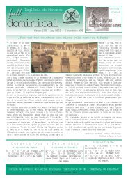
R <strong>1200</strong> <strong>CL</strong><br />
• Technical Features in Detail<br />
• Uncrating & Set up<br />
• Pre Delivery Inspection<br />
• Inspection Procedures (600 Mile)<br />
• Special Tools<br />
• Wiring Diagrams<br />
BMW Motorcycles<br />
Motorcycle Training<br />
J:\BULLETIN\SERVICE\MCTRAINI\Manuals\R<strong>1200</strong><strong>CL</strong>-PDI.qxd<br />
Technical<br />
Training<br />
Motorcycles<br />
09/02
R <strong>1200</strong> <strong>CL</strong><br />
Disclaimer<br />
This training reference book is not intended to be a complete and all inclusive<br />
source of servicing, repairing or troubleshooting the motorcycle. This is only part<br />
of the training information designed to ensure that uniform procedures and<br />
information are presented to all participants of Technical Training conducted by<br />
BMW Motorcycles.<br />
The technician must always refer to and adhere to the following official BMW<br />
Motorrad and BMW North America, Inc service publications.<br />
• Training Materials<br />
• Repair Manuals<br />
• Service Bulletins<br />
• MoDiTeC<br />
Service Bulletins are issued by the BMW Motorcycle Service Department,<br />
regarding changes in operation, and repair or maintenance procedures. Service<br />
Bulletins are available on MTAS (www.bmwmc.net). From the departments menu<br />
button on the home page, select “On-line bulletin search”.<br />
Information Status, (date indicated on front cover).<br />
For changes/additions to the technical data, please refer to current information<br />
issued by the BMW NA Motorcycle Service Department.<br />
BMW of North America, LLC<br />
BMW Motorcycles<br />
ZU-X-S-51<br />
R <strong>1200</strong> <strong>CL</strong> Introduction
R <strong>1200</strong> <strong>CL</strong><br />
Table of Contents<br />
Subject Page<br />
Technical Features in Detail<br />
Introduction . . . . . . . . . . . . . . . . . . . . . . . . . . . . . . . . . . . . . . 2<br />
Engine . . . . . . . . . . . . . . . . . . . . . . . . . . . . . . . . . . . . . . . . . . 4<br />
Clutch . . . . . . . . . . . . . . . . . . . . . . . . . . . . . . . . . . . . . . . . . . 7<br />
Gearbox . . . . . . . . . . . . . . . . . . . . . . . . . . . . . . . . . . . . . . . . 8<br />
Digital Motor Electronics (MA 2.4) . . . . . . . . . . . . . . . . . . . . . 10<br />
Chassis and wheels . . . . . . . . . . . . . . . . . . . . . . . . . . . . . . . 14<br />
Brakes (Integral ABS). . . . . . . . . . . . . . . . . . . . . . . . . . . . . . . 20<br />
Bodywork . . . . . . . . . . . . . . . . . . . . . . . . . . . . . . . . . . . . . . . 24<br />
Headlights . . . . . . . . . . . . . . . . . . . . . . . . . . . . . . . . . . . . . . . 28<br />
Cockpit and Instruments . . . . . . . . . . . . . . . . . . . . . . . . . . . . 30<br />
Electrical components . . . . . . . . . . . . . . . . . . . . . . . . . . . . . . 31<br />
Cruise Control . . . . . . . . . . . . . . . . . . . . . . . . . . . . . . . . . . . . 32<br />
Sound and Communication Systems. . . . . . . . . . . . . . . . . . . 36<br />
Technical data . . . . . . . . . . . . . . . . . . . . . . . . . . . . . . . . . . . . . . 38<br />
Pre Delivery Inspection Procedures . . . . . . . . . . . . . . . . . . . . . 42<br />
Retail Delivery Handover Procedure . . . . . . . . . . . . . . . . . . . . . 61<br />
600 Mile Inspection Procedures . . . . . . . . . . . . . . . . . . . . . . . . 64<br />
New Special Tools . . . . . . . . . . . . . . . . . . . . . . . . . . . . . . . . . . . . 78<br />
Wiring Diagrams<br />
Terminal & Electrical Component Designation Legend . . . . . 83<br />
Power Distribution & Grounds . . . . . . . . . . . . . . . . . . . . . . . . 85<br />
Starter & Alternator . . . . . . . . . . . . . . . . . . . . . . . . . . . . . . . . 89<br />
Motronic MA 2.4 Engine Management. . . . . . . . . . . . . . . . . . 91<br />
Anti-lock Brakes . . . . . . . . . . . . . . . . . . . . . . . . . . . . . . . . . . 97<br />
Cruise Control . . . . . . . . . . . . . . . . . . . . . . . . . . . . . . . . . . . . 99<br />
Instrumentation . . . . . . . . . . . . . . . . . . . . . . . . . . . . . . . . . . . 101<br />
Lights . . . . . . . . . . . . . . . . . . . . . . . . . . . . . . . . . . . . . . . . . . 105<br />
Horn,Turn Indicators with Hazard Flashers . . . . . . . . . . . . . . 107<br />
Radio/CD Player . . . . . . . . . . . . . . . . . . . . . . . . . . . . . . . . . . 109<br />
Heated Grips/Seat and Diagnostic Plug . . . . . . . . . . . . . . . . 111<br />
Alarm System . . . . . . . . . . . . . . . . . . . . . . . . . . . . . . . . . . . . 113<br />
Electrical Component Location Charts . . . . . . . . . . . . . . . . . . 115<br />
Alarm System Components and Programming Information. . 121<br />
R <strong>1200</strong> <strong>CL</strong> Introduction<br />
1
R <strong>1200</strong> <strong>CL</strong><br />
Introduction<br />
The new R <strong>1200</strong> <strong>CL</strong> luxury Cruiser:<br />
individual product personality, visual<br />
appeal featuring unique specifications in<br />
the Cruiser segment.<br />
The distinctive look of the new BMW<br />
boxer flat-twin appeals to the taste of the<br />
individual motorcyclist.<br />
This introduction brochure describes the<br />
technology that lies beneath the skin of the<br />
new BMW R <strong>1200</strong> <strong>CL</strong> in detail as well as<br />
2<br />
Pearl Silver Metallic<br />
uncrating, set up, PDI and maintenance<br />
information. However, allways refer to technical<br />
data in the relevant publications found<br />
the Service and Technical Training areas of<br />
MTAS.<br />
MTAS (Motorcycle Training Administration<br />
System), http://www.bmwmc.net.<br />
We hope you enjoy reading this brochure.<br />
Technical Features in Detail
R <strong>1200</strong> <strong>CL</strong><br />
Introduction<br />
Overview. Assembled at the Berlin plant<br />
with its sister models, the R <strong>1200</strong> <strong>CL</strong> is yet<br />
another milestone for BMW Motorcycles. It<br />
takes its place in the line up of previously<br />
introduced R <strong>1200</strong> C models including the<br />
Classic introduced in 1997, and the later<br />
model variants including the R <strong>1200</strong> C<br />
Montana, Euro, Stilleto and Phoenix, all of<br />
which have laid the foundation for an<br />
extremely successful series.<br />
The name identifies the character of this<br />
new R Series addition; R <strong>1200</strong> <strong>CL</strong>: Cruiser<br />
and Luxury, comfort with everyday suitability<br />
and a powerful appearance.<br />
In addition to the Pearl Silver Metallic shown<br />
on the previous page, color choices at time<br />
of introduction also include:<br />
Mojave Brown Metallic<br />
Capri Blue Metallic<br />
Technical Features in Detail<br />
Equipment Levels. There are two versions;<br />
the base R <strong>1200</strong> <strong>CL</strong> and the higher<br />
trim level R <strong>1200</strong> <strong>CL</strong>C (custom).<br />
In addition to the Fully Integral ABS, other<br />
upgrades are provided as standard equipment<br />
on the base R <strong>1200</strong> <strong>CL</strong> including:<br />
• cruise control,<br />
• two-stage heated grips,<br />
• chrome package,<br />
• and prewiring for the factory stereo<br />
radio/single disc CD player.<br />
The R <strong>1200</strong> <strong>CL</strong>C is additionally equipped<br />
with:<br />
• stereo radio / single disc CD player<br />
with handlebar mounted control,<br />
• heated, comfort seat.<br />
Accessories. Accessories are also available<br />
for both versions including:<br />
• plug in Factory Alarm System,<br />
• Comfort-Squab (separate backrest)<br />
• Top Case Speakers<br />
• Floorboard footrest for passenger<br />
• Cup holder (like K <strong>1200</strong> LT)<br />
• BC-V.O.I.C.E. Board Communications - Voice<br />
Operated Intercom Communication Equipment.<br />
• CB Radio and antenna<br />
• Luggage soft bag inserts for side cases<br />
• Cylinder head engine protection bars<br />
• Side case protection bars<br />
Image.The distinctive fairing silhouette with<br />
the four headlights and innovative bodywork<br />
design integrated standard top and<br />
side case storage concept tempt you to get<br />
on and ride. The riding position, designed<br />
for good handling, provides direct contact<br />
with the motorcycle thanks to the wide handlebars<br />
and low, comfortable seat.<br />
A standard seat height of 745 mm (29.3”)<br />
has been designed intentionally low for all<br />
riders in order to ensure easy control over<br />
the motorcycle when in standing position.<br />
3
R <strong>1200</strong> <strong>CL</strong><br />
Engine<br />
The proven <strong>1200</strong> cc R 259 variant, with<br />
high-camshaft-valve control and four<br />
valves is fitted in the R <strong>1200</strong> <strong>CL</strong> unchanged.<br />
The engine cooling system is handled by<br />
twin oil-coolers integrated in the front<br />
frame. Oil circulation is supplied by its own<br />
oil pump, regulated by a thermostat.The oil<br />
flows through both oil coolers in succession;<br />
lubricating oil and cooling oil are separated.<br />
Engine management is controlled by the<br />
Motronic MA 2.4. in conjunction with the performance-determining<br />
components, such s<br />
camshafts, valve sizes, air intake design, the R<br />
<strong>1200</strong> <strong>CL</strong> engine is also designed in such a<br />
4<br />
way that a torque range desired for a luxury<br />
Cruiser is attained. The engine output of the<br />
R <strong>1200</strong> <strong>CL</strong> is 45 KW (61 bhp) at 5000 RPM,<br />
the maximum torque 98 Nm (71 ft/lb) at<br />
3000 RPM.<br />
The engine’s displacement and dynamic<br />
specifications are:<br />
Displacement = 1170 cc<br />
Bore x Stroke = 101 mm x 73 mm<br />
Pistons = short skirt light alloy box piston<br />
Compression Ratio = 10.0:1,<br />
Camshaft profile = 256°<br />
The exhaust system is designed according<br />
to the bikes cruiser characteristic.<br />
Technical Features in Detail
R <strong>1200</strong> <strong>CL</strong><br />
Engine<br />
The two piece light alloy crankcase is manufactured<br />
using a pressure die-casting<br />
method.The oil pan, which holds 3.75 litres,<br />
is integrated into the engine case halves.<br />
As with all R Series bikes, the engine and<br />
gearbox is a combined load bearing element<br />
of the chassis. For this reason, both<br />
case halves were designed with a specific<br />
rigidity with the aid of computer calculations<br />
of the Finite Element Method.<br />
The 1-piece forged crankshaft is accommodated<br />
centrally in the crankcase on sliding<br />
bearings. It runs on two bearings, the rear<br />
bearing being larger and designed as a<br />
double collar bearing. The 125 mm long<br />
connecting rods are made of sintered steel<br />
and are cracked at the big end.<br />
The weight-optimized box pistons are made<br />
of light alloy and have machined valve<br />
notches on the piston crown. A pressure<br />
release channel above the piston ring zone<br />
prevents a partial vacuum from building up<br />
in the combustion chamber during engine<br />
cool down to prevent oil from being pulled<br />
in under vacuum when the engine is off.<br />
The camshafts are mounted into the cylinder<br />
heads by separate camshaft carriers.<br />
The cams are made up of a case-hardened<br />
shaft with pressed-on individual cams<br />
made of sintered material.<br />
The camshafts are roller chain driven at a<br />
2:1 ratio geared down by the auxiliary shaft,<br />
which is located below the crankshaft and<br />
also drives both duo-centric oil pumps.<br />
The valves all have 5 mm valve stems.They<br />
are actuated in pairs by clear chill cast tappets,<br />
short aluminum tappet push rods and<br />
forged valve lifters.<br />
Technical Features in Detail<br />
Engine Components<br />
Crankshaft / Pistons<br />
Cylinder head / Valve train<br />
5
R <strong>1200</strong> <strong>CL</strong><br />
Engine<br />
The engine is designed to run on premium<br />
grade fuel (95 RON/92 AKI).The air fuel mixture<br />
is ignited by a centrally placed spark<br />
plug.<br />
Directly connected to each spark plug are<br />
the new direct connection ignition coils (ie:<br />
F 650 CS). These coils eliminate the secondary<br />
spark plug wire ensuring consistent<br />
spark voltage over the lifetime of the motorcycle.<br />
Due to the ignition coils, the cylinder<br />
head covers are new.The ignition coils each<br />
have a separate ground wire that connects<br />
to the engine cylinder head.<br />
The exhaust system with a hard chrome<br />
plated surface is produced in three sections:<br />
two exhaust manifolds consisting of a<br />
55 mm double walled tube and a flangemounted,<br />
1-section exhaust silencer with<br />
short tail pipes.This has 4 chambers and is<br />
based on the reflection and absorption principle.<br />
In the exhaust silencer of the R <strong>1200</strong> <strong>CL</strong>, two<br />
catalytic converters are used. The small<br />
diameter and a flat design, offers a higher<br />
sectional flow. The cylindrical catalytic converter<br />
carriers have a diameter of 60 mm<br />
and a length of 74 mm.<br />
The heated O2 sensor is located in the<br />
exhaust gas stream of the two exhaust manifolds<br />
beyond the catalytic converters.<br />
During the warm-up period from 60° C<br />
motor oil temperature (just a few minutes<br />
after starting), it already ensures that the<br />
engine runs in accordance with the stoichiometric<br />
mixture (lambda=1).<br />
The catalytic converters are made of palladium<br />
and rhodium. Palladium accelerates<br />
the oxidation of hydrocarbons and carbon<br />
monoxide. Rhodium reduces nitric oxide.<br />
6<br />
New Ignition Coils<br />
Exhaust Components<br />
Twin Catalytic Converters, Single O 2 Sensor<br />
R <strong>1200</strong> <strong>CL</strong> Introduction
R <strong>1200</strong> <strong>CL</strong><br />
Clutch<br />
Centrifugal mass is of advantage for Cruiser<br />
engine speeds. This is achieved by a solid<br />
clutch case cover with the R <strong>1200</strong> <strong>CL</strong>.<br />
The weight of the clutch disc on the other<br />
hand, with a diameter of only 165 mm, has<br />
been reduced in order to attain a fast standstill<br />
of the gear drive shaft.<br />
This optimizes the engaging and disengaging<br />
of the 6-speed gearbox.The wear resistant<br />
friction lining of the clutch disc together<br />
with the strong casing cover additionally<br />
offers high temperature resistance.<br />
R <strong>1200</strong> <strong>CL</strong> Introduction<br />
Clutch Components<br />
7
R <strong>1200</strong> <strong>CL</strong><br />
Gearbox<br />
The R <strong>1200</strong> <strong>CL</strong> is equipped with a new six<br />
speed Getrag gearbox exhibiting the gearbox<br />
codes:<br />
xxxxxJAE (BMW 7 673 702; GETRAG<br />
424.0.0003.04) = 6 speed, silver painted<br />
xxxxxJAF (BMW 7 673 703; GETRAG<br />
424.0.0003.05) = 6 speed, black painted<br />
8<br />
The first five gears are closely graduated<br />
enabling typical Cruiser riding. The sixth<br />
gear is geared considerably longer and is<br />
therefore designed as an overdrive providing<br />
pleasant touring with lower fuel consumption<br />
on interstate journeys.<br />
In the light alloy casing, three gear shafts<br />
are installed in wear-resistant clean-bearing<br />
deep groove ball bearings.<br />
Technical Features in Detail
R <strong>1200</strong> <strong>CL</strong><br />
Gear Box<br />
The engaging and disengaging gears are<br />
located on the auxiliary shaft and the driven<br />
shaft. All driven gears are installed on lowfriction<br />
needle bearings.<br />
The new heal/toe shifter transfers the riders<br />
shift action to the gearbox through ball and<br />
pin pivots to the input shaft. The heal/toe<br />
shifter is made of chrome plated forged aluminum.<br />
Technical Features in Detail<br />
The aluminum shifter drum is fixed in the<br />
exact gear positions by a cam plate. The<br />
die-cast aluminum shifter forks are actuated<br />
by the shifting gates of the camshaft<br />
controllers via anti-friction steel bushes.The<br />
shifter forks glide smoothly on hollow bored<br />
steel shafts and engage the gears exactly.<br />
The gear pair of the primary drive has a quietly<br />
running, wear-resistant spiral gearing.<br />
All other gears are provided with a spur<br />
toothing and are constructed tightly interlocked.This<br />
provides smoother meshing for<br />
particularly quiet running.<br />
The hollow-bored drive shaft bears a compact,<br />
two phase starting damper. The rotational<br />
oscillations occurring during the idle<br />
speed of the engine are absorbed by a prestressed<br />
washer. A heavy-duty coil spring<br />
works in the main damper, which is responsible<br />
for reducing the noise occurring during<br />
the changing of gear and load.<br />
9
R <strong>1200</strong> <strong>CL</strong><br />
Digital Motor Electronics MA 2.4<br />
The R <strong>1200</strong> <strong>CL</strong> is equipped with Digital<br />
Motor Electronics (Motronic) MA 2.4<br />
engine management system. In contrast<br />
to the Motronic MA 2.4 for the R 1150<br />
models, an electronically regulated cold<br />
start control with idle speed control is<br />
used for the R <strong>1200</strong> <strong>CL</strong>. as on the R <strong>1200</strong><br />
C Classic.<br />
The MA 2.4 control module monitors engine<br />
operating parameters via input signals from<br />
sensors and switches.<br />
10<br />
These input values are evaluated by the<br />
control module and used for calculating the<br />
injection on time and frequency, optimum<br />
ignition timing angle and idle speed control<br />
based on programmed operating data<br />
maps.<br />
This system provides a consistent idle<br />
speed of 900 RPM at normal operating<br />
temperature as well as automatic increased<br />
speeds for cold engine startup which gradually<br />
changes as the engine warms up.<br />
Technical Features in Detail
R <strong>1200</strong> <strong>CL</strong><br />
Digital Motor Electronics MA 2.4<br />
The fuel pump – together with a fuel pressure<br />
regulator – ensure that adequate fuel<br />
volume is available with constant pressure<br />
to the fuel injectors. The fuel pump is<br />
switched on by the fuel pump relay which is<br />
controlled by the MA 2.4 control module.The<br />
fuel system pressure in the distributor is<br />
constant 3 bar.<br />
The Motronic control module receives the<br />
most important input signals from the hall<br />
sensors (crankshaft rotational speed and<br />
top dead center piston position) and from<br />
the throttle position sensor (angular position<br />
of the throttle valves).<br />
Technical Features in Detail<br />
The air volume drawn in is calculated (Alphan-control)<br />
via the angle of the throttle valve<br />
(Alpha) and the engine speed. The fine-tuning<br />
takes place via an engine temperature<br />
sensor, and the air temperature sensor and<br />
the integrated barometric pressure sensor.<br />
The oxygen sensor monitors the amount of<br />
remaining oxygen content in the exhaust<br />
gas. This allows the control module to<br />
manipulate the fuel injector on time (Ti) to<br />
maintain the optimum air fuel mixture. All<br />
information is compared with the programmed<br />
characteristics in the control unit.<br />
11
R <strong>1200</strong> <strong>CL</strong><br />
Digital Motor Electronics MA 2.4<br />
The output signals for ignition and injection<br />
are amplified in the control module by integrated<br />
output transistors. The transistors<br />
switching on and off activates the fuel injector<br />
solenoid valves and the primary ignition<br />
coil windings.<br />
The cold-start control works with an actuator<br />
with a worm gear pair that directly actuates<br />
the two throttle valves in the intake<br />
manifold. The control signal is calculated<br />
from the signals of the engine temperature<br />
and from the speed of the crankshaft with<br />
response.<br />
The ideal positions of the throttle valves are<br />
set for all operational states by means of an<br />
adaptive control adjustment maintained by<br />
the control module.<br />
12<br />
The fuel injectors are small and light weight.<br />
They inject fuel once per crankshaft revolution<br />
in parallel.<br />
To achieve optimal running of the engine<br />
during the start-up and warming phase, fuel<br />
enrichment is provided by activating the<br />
injectors twice as often during starting<br />
phase, then switching over to the once per<br />
crankshaft revolution injection scheme with<br />
a longer ontime to proved enrichment. As<br />
the engine warms the on time is reduced.<br />
When the maximum engine speed of 7000<br />
rpm has been reached, the injection time is<br />
interrupted in order to limit the speed.<br />
Technical Features in Detail
R <strong>1200</strong> <strong>CL</strong><br />
Digital Motor Electronics MA 2.4<br />
The Motronic is equipped with a fuel cut-off.<br />
If throttle valves are closed, an engine temperature<br />
is more than 70° C or an engine<br />
speed exceeds 1800 rpm, then the activation<br />
of the fuel injectors is interrupted.When<br />
the engine speed reduces to 1400 RPM or<br />
below, the injectors are reactivated.<br />
The failure of a sensor signal (with the<br />
exception of Hall sensors) is detected by<br />
the control module through electrical monitoring<br />
and plausibility. When this happens,<br />
a fault is set for the failed input signal and<br />
alternate default value is used allowing the<br />
motorcycle to continue running.<br />
Technical Features in Detail<br />
MA 2.4 communicates with BMW diagnostic<br />
equipment (MoDiTeC / GT 1) via the 10<br />
pin diagnostic plug located under the left<br />
side chrome cover.<br />
13
R <strong>1200</strong> <strong>CL</strong><br />
Chassis and Wheels<br />
The R <strong>1200</strong> <strong>CL</strong> has a wheelbase of<br />
1641mm, which is actually 9mm shorter<br />
than the Classic. The rake angle and trail<br />
measurement have also been changed.<br />
The chassis geometry was re-considered<br />
for the R <strong>1200</strong> <strong>CL</strong> due to the wider tires and<br />
the different character required for a Luxury<br />
Cruiser. The angles were a calculated decision,<br />
resulting in both appearance and<br />
functionality. These changes necessitated<br />
the following new components specifically<br />
made for this bike;<br />
• 30 mm longer telelever control arm,<br />
• wider chrome plated upper fork bridge,<br />
• wider lower fork brace with repositioned<br />
ball joint mounting socket<br />
14<br />
Additionally, the attachment points for the<br />
brake calipers had to be modified to comply<br />
with the EVO caliper dimensions requiring<br />
new stanchion tubes for the front forks.<br />
The telelever control arm pivots at the<br />
engine mounting location on a continuous<br />
hollow shaft, which is held in maintenancefree<br />
ball bearings.<br />
The front frame section is made of die cast<br />
aluminum, which is the best method for<br />
moulding shapes and surfaces. It’s firmly<br />
attached to the crankcase at four points.<br />
The cast frame provides a mounting point<br />
for the new chrome plated, forged aluminum,<br />
upper fork bridge. The fork bridge<br />
steering bearings are reinforced doublerow<br />
flute bearings.<br />
Technical Features in Detail
R <strong>1200</strong> <strong>CL</strong><br />
Chassis and Wheels<br />
To prevent rocking movements in the steering system, the fork tubes are mounted to the<br />
newly designed upper fork bridge by tilt decoupled barrel joints.<br />
The fork tubes are mounted 225 mm apart from each other and connected by a new<br />
chrome plated, forged aluminum, lower fork brace. It is mounted to the forks by bolts<br />
ensuring the rigidity of the front wheel location. The lower fork brace is connected to the<br />
30mm longer longitudinal control arm by the typical Telelever maintenance free ball joint.<br />
Technical Features in Detail<br />
15
R <strong>1200</strong> <strong>CL</strong><br />
Chassis and Wheels<br />
The travel of the front wheel is damped by a<br />
central suspension strut with twin-sleeve<br />
damper principle. It provides 144 mm of<br />
front suspension travel.<br />
To review the changes in the chassis geometry<br />
we will compare the R <strong>1200</strong> C to the<br />
<strong>CL</strong>. But first lets review the basics of chassis<br />
geometry.<br />
Rake = The inclined angle that is created<br />
by an imaginary line through the steering<br />
pivots to the road surface.<br />
Trail = The distance, as measured along the<br />
ground, of the point at which the front tire<br />
contacts the ground and where the imaginary<br />
axis line of the steering pivots would<br />
contact the ground.<br />
By itself, the 30mm longer R <strong>1200</strong> <strong>CL</strong><br />
Telelever changes the rake angle to 56 O<br />
and increases the wheelbase by the same<br />
distance.<br />
However, the new lower fork brace repositions<br />
the steering pivot further forward on<br />
the fork brace, which moves the forks rearward<br />
reducing the overall wheelbase but<br />
increases the trail.<br />
Final chassis specifications of R <strong>1200</strong> C<br />
vs R <strong>1200</strong> <strong>CL</strong>:<br />
Rake angle:<br />
C = 60.5 O<br />
<strong>CL</strong> = 56 O<br />
Trail measurement:<br />
C = 86mm (3.38“)<br />
<strong>CL</strong> = 184mm (7.24“)<br />
Wheelbase:<br />
C = 1650 mm (65.0“)<br />
<strong>CL</strong> = 1641 mm (64.61“)<br />
16<br />
Technical Features in Detail
R <strong>1200</strong> <strong>CL</strong><br />
Chassis and Wheels<br />
The Monolever swing arm is fixed very rigidly<br />
– in central cast steel parts – in backlash<br />
free taper roller bearings, thereby resulting in<br />
a short, rigid connection between the bearing<br />
of the rear wheel swing arm and the longitudinal<br />
control arm.<br />
The welded monolever consists of extremely<br />
strong molded steel parts.The monolever<br />
has been structurally reinforced in the area<br />
of the spring strut support and the extruded<br />
sections.<br />
The swing arm is 612 mm long which has<br />
remained the same length in order to realize<br />
the seat position behind the rear wheel and<br />
the classical directional stability of a Cruiser.<br />
The forces of the Monolever spring strut are<br />
absorbed above the swinging arm bearing,<br />
which are distributed optimally in the tension<br />
struts of the frame triangle.<br />
The new spring strut is equipped with a single<br />
sleeve damper and the pre-load of the<br />
spring can be easily adjusted hydraulically<br />
with a hand adjustment knob.<br />
The rear wheel has 120 mm of travel. The<br />
damper system is identified as W.A.D.,<br />
which is a german acronym for travel related<br />
dampening.<br />
This principle works in the compression<br />
stroke with a needle valve that closes off a<br />
fluid dampening section within the strut to<br />
increase damping when travel movement<br />
comes close to the end limits.<br />
Technical Features in Detail<br />
17
R <strong>1200</strong> <strong>CL</strong><br />
Chassis and Wheels<br />
The rear frame section is welded together<br />
by a combination of tubular, cast and forged<br />
steel components. The frame is then paint<br />
finish coated.<br />
Cast steel bearings for supporting the foot<br />
pegs of the rider and pillion are welded to<br />
the frame. They are attached to the engine<br />
in the area of the longitudinal control arm<br />
bearing, the oil pan and on the considerably<br />
reinforced light metal-gearbox case.<br />
18<br />
Tail Frame Section<br />
Due to the longer seat system and the addition<br />
of the top case, the rear frame is<br />
lengthened accordingly. The side cases are<br />
mounted to tubular frame extensions providing<br />
a screw mounting point.The left side<br />
extension is removable for tire service by<br />
removing four screws.<br />
Front Wheel<br />
R <strong>1200</strong> <strong>CL</strong> Introduction
R <strong>1200</strong> <strong>CL</strong><br />
Chassis and Wheels<br />
The new die-cast aluminum wheels with<br />
their five double spokes radiate dynamic<br />
performance and are visually supported by<br />
the powerful large tires.<br />
The rear wheel measures 4.0 x 15 with tire<br />
measuring 170/80 VR 15 for good traction,<br />
high mileage and ride comfort.<br />
The wheel is screwed directly to the rear<br />
axle with four wheel-bolts enabling the<br />
wheel to be removed easily once the side<br />
case is removed or with a service lift with a<br />
removable floor.<br />
The front wheel measures 3.5 x 16 with tire<br />
measuring 150/80 VR 16 for the best braking<br />
efficiency and comfort. The front wheel<br />
axle is also new. It’s length has been<br />
increased due to the wider spacing.<br />
Removal of the rear wheel is simplified by<br />
the use of the accessory service stand jack<br />
and a detachable rear frame that is accessible<br />
from behind the left side saddle bag.<br />
The rear wheel can be removed without<br />
removing the side frame if the motorcycle is<br />
on a service lift with a removal rear wheel<br />
floor.<br />
• Detach the case 2 x T25 + 2 x T30<br />
• Case mount (frame section) 4 x T40<br />
• Rear wheel bolt 4 x M12 x 60.<br />
• Note the intermediate spacer.<br />
Technical Features in Detail<br />
Front & Rear Wheels<br />
Frame Case Mount Removal/Installation<br />
Spacer Plate<br />
Rear Wheel Removal/Installation<br />
4 x T20<br />
Torque<br />
to 20 Nm<br />
when reinstalling<br />
105 Nm<br />
(cross pattern)<br />
19
R <strong>1200</strong> <strong>CL</strong><br />
Brake Components and Integral ABS<br />
The brake system has been designed to<br />
meet the demands of a touring Cruiser. The<br />
EVO brake and fully integral ABS are used<br />
for the first time on the R <strong>1200</strong> C model.<br />
The large 305mm floating brake discs made<br />
of high-grade steel are used on the front<br />
wheel. The bearings are connected directly<br />
to the hub of the front wheel by means of a<br />
secondary support and five screws. Drilled<br />
discs enhance the brake reaction in wet<br />
conditions and increase the self-cleaning<br />
effect.<br />
The two hydraulically operated 4-piston<br />
calipers are designed as fixed calipers providing<br />
angular wear compensation due to<br />
the offset piston diameters. The piston<br />
diameters are 36 or 32 mm.<br />
20<br />
The sintered metal brake pads have a brake<br />
pad surface of 86 cm 2 .The rear wheel brake<br />
is a hydraulically operated single disc brake<br />
with 4-piston caliper and organic brake<br />
pads. It has been taken over essentially<br />
from the K <strong>1200</strong> LT model.<br />
The floating high-grade steel brake disc<br />
screwed to the ring gear of the rear axle has<br />
retained the diameter of 285 mm. The thickness<br />
of the disc has been increased to 7 mm.<br />
A visual wear indicator is mounted on the<br />
steel support of the outer brake pad to<br />
make it easy to check the available pad<br />
thickness as the brakes where and as an<br />
indicator that they require replacement.<br />
Technical Features in Detail
R <strong>1200</strong> <strong>CL</strong><br />
Brake Components and Integral ABS<br />
Technical Features in Detail<br />
New!<br />
Brake Pad Wear Indicator<br />
When the tab of the indicator<br />
touches the pad on the other<br />
side, replace the pads.<br />
21
R <strong>1200</strong> <strong>CL</strong><br />
Brake Components and Integral ABS<br />
The BMW fully integral ABS enables the<br />
braking efficiency to be distributed via electronic<br />
control ensuring optimal braking<br />
power is always available on each wheel. At<br />
the same time, influencing factors such as<br />
dynamic wheel load distribution, load and<br />
temperature of the brakes are taken into<br />
account. In addition, the system includes<br />
the antilock function so that a reliable braking<br />
function is available on the motorcycle.<br />
The system’s integrated brake booster<br />
keeps the operating force of the brake lever<br />
low for the rider. With the fully integral variant,<br />
the front and rear control circuits are<br />
connected by integral pistons in the pressure<br />
modulator that the front and rear wheel<br />
brakes are activated automatically when the<br />
hand lever or rear pedal are operated.<br />
22<br />
The fully integral pressure modulator of the<br />
R <strong>1200</strong> <strong>CL</strong> is installed beneath the tank.The<br />
brake fluid reservoirs for the front and rear<br />
wheel circuit are located in the pressure<br />
modulator as on all R series bikes. The<br />
brake fluid reservoir for the front control circuit<br />
is located in the hand lever master<br />
cylinder. The rear control circuit reservoir is<br />
connected to the brake pedal master cylinder<br />
via a feed line (green line in illustration).<br />
As with all versions of the Integral ABS, the<br />
modulator control valves are designed to<br />
provide the residual braking function, which<br />
connects the control circuits and wheel circuits<br />
via piston movement (hydraulic over<br />
hydraulic control). This safety feature<br />
ensures adequate brake function if the ignition<br />
is turned off or if the Integral ABS is<br />
defective.<br />
Technical Features in Detail
R <strong>1200</strong> <strong>CL</strong><br />
Brake Components and Integral ABS<br />
The other lines run as follows:<br />
• The orange line (actuating pressure) and<br />
the yellow line (brake actuator signal) run<br />
from the handbrake lever to the pressure<br />
modulator.<br />
• The orange line (actuating pressure) and<br />
the yellow line (brake actuator signal) run<br />
from the foot brake lever to the pressure<br />
modulator. Furthermore, the green line<br />
comes from the brake fluid reservoir to<br />
the foot brake cylinder.<br />
• The red lines run from the pressure modulator<br />
(wheel circuit) to the front wheel<br />
and rear wheel brake calipers.<br />
• The sensor signals (blue) come from the<br />
front and rear wheel to the controller.<br />
• The warning lights in the cockpit are controlled<br />
via the blue lines.<br />
Technical Features in Detail<br />
The new light weight speed sensor trigger<br />
rings in combination with the active wheel<br />
speed sensors recognize wheel locking<br />
tendencies much faster than the previous<br />
analog inductive sensors.<br />
The speed sensor signals are input to the<br />
Integral ABS control module for continual<br />
processing and are also output to provide a<br />
speedometer signal for systems requiring<br />
accurate speed information such as the<br />
cruise control and speedometer.<br />
The system also monitors the function of<br />
the brake light and rear light and indicates<br />
their failure when necessary. If a rear light is<br />
defective, the dimmed brake light takes over<br />
its function.<br />
The general warning light and an ABS warning<br />
light are located in the cockpit for indicating<br />
possible defects or faults.<br />
23
R <strong>1200</strong> <strong>CL</strong><br />
Bodywork<br />
The front fairing integrated headlights<br />
give this motorcycle a very distinctive<br />
visual appeal.<br />
The fairing integrated mirrors (which also<br />
house the direction indicator lights), and the<br />
permanently fixed windshield, the 3-part<br />
fairing harmoniously combines Cruiser and<br />
tourer features, providing a new standard for<br />
luxury cruising.<br />
The tank and side trim panel parts are distinctive<br />
with the ergonomics of the knee<br />
angle and the aerodynamically optimized air<br />
outlets of the oil coolers which provide<br />
additional leg protection.<br />
24<br />
These combined features result in a casual,<br />
pleasant seating position, the anatomy of<br />
the knee angle being particularly distinguished<br />
in the area of the air filter cover. The<br />
painted wide rear fender emphasizes the<br />
bikes stretched lines.<br />
The front fairing attached to the handlebars<br />
protects effectively against disturbing wind<br />
pressure and turbulence. Transparent wind<br />
guide vanes attached to the fairing ensure<br />
that additional water and dirt is deflected<br />
mainly from the passenger.<br />
Technical Features in Detail
R <strong>1200</strong> <strong>CL</strong><br />
Bodywork<br />
There are two windshield versions; low and<br />
high.The US market will receive the low version<br />
as standard equipment. The high version<br />
can be purchased as an accessory.<br />
Both types are distinctive thanks to their<br />
functional design, which is cut lower in a<br />
curved arch in the rider’s field of vision.<br />
Technical Features in Detail<br />
The advantage is not only an enhanced field<br />
of vision in wet and dusty conditions. But at<br />
high speeds in particular, the ingenious<br />
recess improves the protection in the area<br />
of the shoulder and provides added wind<br />
protection for the passenger.<br />
25
R <strong>1200</strong> <strong>CL</strong><br />
Bodywork<br />
The mirror housings are designed as aerodynamic<br />
hand protectors. They are ventilated<br />
at the rear in order to prevent turbulence<br />
from forming on the handlebar grips. The<br />
rear-view mirrors can be quickly removed<br />
from the fairing by means ball sockets (ie: K<br />
<strong>1200</strong> LT, R 1150 RT).<br />
The fuel tank trim panels protect the rider’s<br />
legs against the air stream and have integrated<br />
rain deflectors built in by design<br />
(edges flair outward).<br />
The panels are hollow plastic covers that<br />
attach to sheet steel carriers by screws.<br />
The space between the colored covers and<br />
steel carries houses a portion of the motorcycles<br />
electronic equipment (left side:<br />
optional Anti Theft System, right side: cruise<br />
control module). The side trim panels do<br />
not have to be removed if the fuel tank is<br />
removed.<br />
The handlebars are made from a 3.5 mm<br />
thick steel tube and have a diameter of<br />
28mm. The surface is coated with hard<br />
chrome. Handlebar weights are fitted at the<br />
ends of the handlebars for damping vibration.<br />
Perfect seating comfort includes the feet<br />
too: Running boards made of forged aluminum<br />
and vibration decoupled for the rider<br />
by rubber bearings and wide passenger<br />
foot rests derived from the K <strong>1200</strong> LT guarantee<br />
good foothold, and combined with<br />
the pleasant knee angle, ensure relaxed riding.<br />
26<br />
The seats include optional heating elements<br />
(standard on the <strong>CL</strong>C). The boldly<br />
designed border of the upper passenger<br />
supporting straps makes the luggage<br />
bridge a real eye catcher.<br />
A special feature of the side cases is the<br />
one-hand closing concept. After pressing<br />
the lock cylinder in, the flush finger lift lever<br />
springs up to unlatch the cover. When<br />
closed, the case cover latching system<br />
evenly compresses the lid into the seal by<br />
four integrated tension rods.<br />
A same key lock set is equipped with the<br />
motorcycle allowing a single key to operate<br />
the ignition lock/steering lock, filler cap and<br />
luggage system.<br />
The luggage system is integrated into the<br />
overall appearance of the R <strong>1200</strong> <strong>CL</strong>. The<br />
top case with a volume of 45 litres providing<br />
plenty of space for luggage.The central<br />
handle easily operates the latch and locking<br />
system as on the K <strong>1200</strong> LT. The combined<br />
side case volume of approximately 63 litres<br />
brings the total lockable storage capacity of<br />
the R <strong>1200</strong> <strong>CL</strong> to 108 litres.<br />
Case Capacities:<br />
Top Case = 45 liter (1.59 cu ft)<br />
Left Case = 33 liters (1.16 cu ft)<br />
Right Case = 30 liters (1.06 cu ft)<br />
Technical Features in Detail
R <strong>1200</strong> <strong>CL</strong><br />
Bodywork<br />
Technical Features in Detail<br />
27
R <strong>1200</strong> <strong>CL</strong><br />
Headlights<br />
The four round headlights have been integrated<br />
in a new arrangement never before<br />
used on a BMW Motorcycle. The headlamps<br />
are mounted to an adjustable support<br />
made of a synthetic material.<br />
They consist of two larger low beam headlights<br />
and two smaller high beam headlights<br />
positioned one on top of the other.<br />
The low beam headlights work with an H4light<br />
and can be readjusted from the front.<br />
The high beam headlights with H1-lights<br />
enable wide illumination of the road with<br />
their scattered light.<br />
The park lamps with 4-watt conventional<br />
bulbs are installed in the low beam headlights.<br />
All electric light bulbs can be<br />
replaced from the outside after removing<br />
each inner trim.<br />
28<br />
The beam distance can be adjusted to<br />
compensate for two up riding with the<br />
spring-loaded lever located on left side of<br />
fairing rear surface. For normal position,<br />
lever is up, to adjust flip down (as shown).<br />
Load compensation light beam adjustment lever<br />
Technical Features in Detail
R <strong>1200</strong> <strong>CL</strong><br />
Headlights<br />
Lever Positions:<br />
Horizontal: normal position (shown); Always<br />
adjust base setting of headlights with lever<br />
in this position.<br />
Flipped down: position for 2 up with luggage<br />
(shown on previous page).<br />
The adjustment screw found in the center of<br />
the load adjustment lever is used to establish<br />
the base headlight position of the total<br />
headlamp assembly. This screw simultaneously<br />
adjusts the vertical position of all four<br />
headlights.<br />
R <strong>1200</strong> <strong>CL</strong> Introduction<br />
Base setting adjustment screw<br />
29
R <strong>1200</strong> <strong>CL</strong><br />
Cockpit and Instruments<br />
The central component in the cockpit is the<br />
instrument cluster with its three round<br />
gauges and the centrally located ignition<br />
lock.<br />
The instruments are housed in an aluminum<br />
cockpit-support that is mounted on the fork<br />
brace. The cover glass and functionally<br />
designed analog instruments feature<br />
chrome rings. The electronic tachometer is<br />
large and easily read. The analog clock, is<br />
mounted high and centered always in the<br />
rider’s field of vision. The time can be<br />
adjusted easily by using the large rubber<br />
pushbutton located on the right hand side<br />
of the clock.<br />
The speedometer’s integrated digital LCD<br />
display includes a mileage meter that can<br />
be reset with the left reset button. The<br />
mileage indicator retains the setting selected<br />
prior to switching off the ignition, i.e.<br />
odometer or trip meter.<br />
30<br />
The warning lamps and signal indicators in<br />
the three centrally located rows are LEDs.<br />
• Top: green turn signals, red engine oil<br />
pressure and battery charge indicators.<br />
• Middle: Two red ABS, green neutral and<br />
round red Anti Theft<br />
• Bottom: Yellow reserve fuel indicator that<br />
flashes when the level reaches 4 liters, a<br />
blue high beam and the yellow cruise<br />
control indicators<br />
The clutch and brake levers are adjustable<br />
in order to ensure better ergonomics.There<br />
is a two stage heated-grip flip switch (50<br />
and 100%) on the right side combination<br />
switch.<br />
Technical Features in Detail
R <strong>1200</strong> <strong>CL</strong><br />
Electrical Components<br />
3<br />
11<br />
The neatly arranged electrical system is<br />
located under the fuel tank and is the<br />
basis for operating the electrical components.<br />
In addition to the distribution system<br />
technology and high quality connectors,<br />
the new wiring harness provides the<br />
possibility of options such as the Anti<br />
Theft System to simply plug into wiring<br />
provisions.<br />
The Motronic control module is located<br />
above the central electrical control box.<br />
Different electrical accessories can be connected<br />
to the wiring harness via the preinstalled<br />
special accessory-terminal.<br />
The electronic speedometer is supplied<br />
with a processed speed signal from the<br />
Integral ABS control module.The turn signal<br />
indicator relay is also fed with the speed<br />
signal, which ensures that the direction<br />
indicator is reset after approx. 210 m and/or<br />
11 seconds.<br />
Technical Features in Detail<br />
4<br />
1<br />
5<br />
2<br />
6<br />
7<br />
8<br />
9<br />
10<br />
Electrical components:<br />
1 Blinker/Flasher module<br />
2 Fuel level indicator<br />
dampening module<br />
3 High beam relay (yellow)<br />
4 Starter relay<br />
5 Low beam relay (yellow)<br />
6 ABS warning relay<br />
7 Motronic relay<br />
8 Fuel pump relay<br />
9 Horn relay<br />
10 Load Shed Relay<br />
11Terminal connection for<br />
Ignition and light switch<br />
Not pictured - located<br />
under starter relay is<br />
starting system diode<br />
The light-emitting diode for the reserve fuel<br />
is controlled via an electronic module,<br />
which has a time delay of 17 seconds.<br />
The alternator’s maximum output is 840<br />
Watt, of which 300 watts is available at<br />
engine idle speed.The compact battery has<br />
a capacity of 19 Ah.<br />
Cranking the engine is accomplished with<br />
an 1.1-kW planetary gear starter. Cranking is<br />
only possible when the gear box is in neutral<br />
or in gear with the clutch lever pulled in.<br />
Only then is there voltage on the coil of the<br />
ignition relay via the clutch lever and gear<br />
lever. Starting is only possible after the prop<br />
stand has been folded in. This is a typical<br />
safety feature of BMW. If a gear change is<br />
made when the side prop is folded out, then<br />
the Motronic relay is switched off.<br />
Two easily accessible fuse boxes with new<br />
mini fuses are arranged behind the left air<br />
filter cover.<br />
31
R <strong>1200</strong> <strong>CL</strong><br />
Cruise Control<br />
With the introduction of the R <strong>1200</strong> <strong>CL</strong>,<br />
cruise control is equipped for the first<br />
time on a BMW boxer. It is ideally suited<br />
for a luxury Cruiser, because it allows<br />
particularly relaxed riding both on interstates<br />
as well as secondary roads.<br />
The system electronics is carry over from<br />
the K <strong>1200</strong> LT. It is operated from the left<br />
combination switch. The system is turned<br />
on with the slide switch which also unlocks<br />
Set/ Resume pushbutton.<br />
A function light in the left combination<br />
switch also indicates that the system is<br />
ready. The SET LED in the central indicator<br />
display signals to the rider that the cruise<br />
control is activated.<br />
By pressing the pushbutton key in the forward<br />
direction, the current speed is stored<br />
in the control unit and kept adjusted to the<br />
accelerator cable by the cruise control.This<br />
is approx. 45 to 145 Km/h, which corresponds<br />
to 2/3 of the throttle valve opening.<br />
This is reset in the control unit by a stepper<br />
motor via an electromagnetic clutch and roll<br />
band. Thus, a fine adjustment of the speed<br />
is also possible.<br />
32<br />
This is done in intervals of approx. 1.6 km/h<br />
by tipping the pushbutton.<br />
• In the direction of SET: accelerate<br />
• In the direction of RES: decelerate<br />
If the SET function is deactivated, the last<br />
speed saved in the controller can be<br />
retrieved and set by pressing the pushbutton<br />
key in the direction of RES.<br />
The following operations cause the electromagnetic<br />
clutch to be switched off immediately<br />
thereby deactivating the cruise control:<br />
• Operating the brake or clutch<br />
• Turning back the throttle twist grip<br />
• Accelerating to more than 160 km/h<br />
• Setting the slide switch to OFF<br />
Cruise Control System Test: The cruise<br />
control system does not have a fault code<br />
memory. It does however convey functional<br />
confirmation through control of the SET<br />
indicator in the instrument cluster. This is<br />
known as the Cruise Control Self Test which<br />
can be done via MoDiTeC or by following<br />
the stand alone test on next page.<br />
When the SET indicator fails to change status<br />
in a phase of the test, it indicates a circuit<br />
problem in that area of the system.<br />
Refer to wiring diagram and check circuit(s)<br />
and components of circuit.<br />
Technical Features in Detail
R <strong>1200</strong> <strong>CL</strong><br />
1. With the ignition in the OFF position<br />
switch the cruise control switch to ON.<br />
Press and hold the cruise control button<br />
in the SET position and turn the ignition<br />
switch to ON. SET indicator goes ON.<br />
When you release the button the SET<br />
Indicator in the cluster goes OFF.<br />
2. Press and hold the cruise control button<br />
in the RESET position. SET indicator ON.<br />
Release button, SET indicator goes OFF.<br />
3. Switch the cruise control switch to OFF<br />
position. SET indicator goes ON.<br />
4. Switch the cruise control switch back to<br />
ON. SET indicator in the cluster goes OFF.<br />
5.Twist throttle grip back against detent<br />
until you feel click of microswitch. SET<br />
indicator goes ON. Release throttle grip.<br />
SET indicator in the cluster goes OFF.<br />
Technical Features in Detail<br />
6. Pull clutch lever in fully. SET Indicator in<br />
cluster goes ON. Release, goes OFF.<br />
7. Pull front brake lever. SET indicator in<br />
cluster goes ON. Release, goes OFF.<br />
8. Repeat Step 7, but hold for 5 seconds<br />
until the SET indicator automatically goes<br />
OFF. Then release brake lever and remove<br />
hand from throttle.<br />
9. Once brake is released, the cruise control<br />
module activates the motor. Listen for<br />
a click.<br />
10. Rotate the rear wheel to generate a<br />
speed signal; SET indicator in cluster<br />
blinks Flashes ON and OFF. (Roll motorcycle<br />
on shop floor)<br />
Switch Ignition OFF, end of Test.<br />
33
R <strong>1200</strong> <strong>CL</strong><br />
Cruise Control<br />
The R <strong>1200</strong> <strong>CL</strong> uses a new cable control<br />
box to converge the operation of the throttle<br />
from either the opener/closer cables of<br />
the throttle grip or the control cable from<br />
the cruise control actuator.<br />
The box is located behind the fairing and<br />
headlight assembly both of which require<br />
removal to access. The box interconnects<br />
four cables with two pulleys. It also contains<br />
a microswitch that signals the cruise<br />
control module when the throttle is turned<br />
in the close direction to cancel cruise function<br />
The spring tensioned pulleys rotate on a<br />
shared axis. The lower pulley is attached to<br />
the opener cable, the closer cable and the<br />
throttle cable. The upper pulley is connected<br />
to the cruise control cable.<br />
The pulleys rotate freely from one another<br />
when the throttle is operated from the grip.<br />
In this function, the twist grip pulls the<br />
opener cable which simultaneously pulls<br />
the throttle cable at the lower pulley.<br />
When the cruise control actuator pulls the<br />
cruise cable, the upper pulley rotates. A pin<br />
on the upper pulley engages the lower pulley<br />
and simultaneously operates the throttle.<br />
The pin on the upper pulley and the slot on<br />
the lower pulley are keyed to allow full grip<br />
control to over ride the cruise control function.<br />
When the twist grip is turned in the<br />
opposite direction the closer cable is tensioned<br />
which activates the closer switch,<br />
signalling the cruise control to deactivate if<br />
currently active.<br />
There are four adjustment points on the<br />
cables to adjust cable play. They are at the<br />
twist grip and at the cable unions under the<br />
fairing just forward of the spring damper.<br />
34<br />
Closer cable<br />
Cruise cable<br />
Cable box location<br />
Cable Box internal view<br />
Opener cable<br />
Cable Box<br />
Throttle cable<br />
R <strong>1200</strong> <strong>CL</strong> Introduction
R <strong>1200</strong> <strong>CL</strong><br />
Cruise Control<br />
Technical Features in Detail<br />
35
R <strong>1200</strong> <strong>CL</strong><br />
Sound and Communication System<br />
The R <strong>1200</strong> <strong>CL</strong>C is equipped with the Stereo<br />
Radio with Single Player CD as standard<br />
equipment. The Base R <strong>1200</strong> <strong>CL</strong> is prewired<br />
to accept the equipment as an accessory.<br />
The system consists of the combined radio<br />
electronics/single CD player located in the<br />
right side case, the radio controller on the<br />
left hand handlebar, and the centrally mounted<br />
display/control panel. The radio unit with<br />
RDS and a scan-function.<br />
The output stages for the loudspeakers can<br />
be controlled separately, enabling the sound<br />
to be distributed individually via the balance<br />
and fader.<br />
The two standard 20-watt loudspeaker units<br />
each consist of a broad-band loudspeaker.<br />
With regard to the best sound quality, these<br />
are contained in enclosed boxes with the<br />
same volume.<br />
36<br />
The sound system mounted on the handlebar<br />
clamp in the rider’s field of vision can be<br />
switched on and off in the central control<br />
panel with a digital display.<br />
All functions are selected via illuminated<br />
buttons. The rider can easily select the volume,<br />
radio stations, station finding, mutefunction<br />
and radio traffic service by operating<br />
the standard remote control on the left<br />
grip control.<br />
The station finding can be operated manually<br />
or automatically with two levels of sensitivity.<br />
The scan-function searches for the<br />
next station or title and plays it for ten seconds.The<br />
volume can be reduced by 20 dB<br />
with the mute-function. The CD-drive is<br />
operated electronically and can be used for<br />
normal audio CDs.<br />
Technical Features in Detail
R <strong>1200</strong> <strong>CL</strong><br />
Sound and Communication System<br />
The right side case also includes a cooling<br />
fan system for the electronics. The fan runs<br />
continuously whenever the Radio/CD is<br />
switched on. Make sure nothing obstructs<br />
the intake air grill around the fan when loading<br />
the right side case.<br />
A practical extension to the sound system<br />
is the newly developed BC-Voice (onboard<br />
communication system) available as a special<br />
accessory. The VOICE system module<br />
mounts beneath the radio, but is controlled<br />
by the radio control panel due to interconnection<br />
of the two systems.<br />
The connection terminals for the mobile<br />
telephone and radio are also inserted into<br />
the front panel of the BC-VOICE.<br />
Telephone calls can be received if the<br />
device has an automatic call receiver and if<br />
a small mobile radio telephone antenna is<br />
used. The radio connection is intended for<br />
Family Radio Band (Free Talk) two way<br />
radios.<br />
Look for accessory installation instructions<br />
for the BC VOICE system on MTAS.<br />
A new easily detachable dielectric rod<br />
antenna and base union are being introduced<br />
on the R <strong>1200</strong> <strong>CL</strong>. This new style<br />
union offers simplified removal and reinstallation<br />
when necessary for cover use.<br />
The antenna is decoupled from the base<br />
using an special tool found in the tool kit<br />
and unscrewing the union. The contact is<br />
more robust than previous antennas ensuring<br />
proper connection everytime.<br />
Technical Features in Detail<br />
BC VOICE installed position / Cooling Fan<br />
Dieletric Antenna<br />
37
R <strong>1200</strong> <strong>CL</strong><br />
Technical Data<br />
Engine:<br />
Performance<br />
Max. torque<br />
Bore<br />
Stroke<br />
Effective capacity<br />
Stroke/bore ratio<br />
Compression ratio<br />
Fuel<br />
Angle of valve in relation to the cylinder axis<br />
Valve diameter Intake:<br />
Exhaust:<br />
Camshaft<br />
Valve timing at 3 mm valve play<br />
Valve stroke (without valve play)<br />
Engine oil volume<br />
Oil filter<br />
Oil pumps<br />
Lubricating Circuit Oil Pressure<br />
Engine cooling:<br />
Flow rate of the pump<br />
Start of opening of the thermostat valve<br />
Air/oil-cooled 2-cylinder 4-stroke boxer<br />
engine with four rocker arm operated<br />
valves, each with overhead camshaft and<br />
wet lubrication with two oil coolers<br />
45 kW (61 hp) @ 5000 rpm<br />
98 Nm (71 ft/lb) @ 3000 rpm<br />
101 mm (3.98”)<br />
73 mm (2.87”)<br />
1170 cm 3 (71.4 cubic inches)<br />
0.72<br />
10.0 : 1<br />
Unleaded regular grade fuel, 95 RON<br />
Intake: 19°<br />
Exhaust: 22°<br />
34 mm (1.34”)<br />
29 mm (1.14”)<br />
256°<br />
Intake opens 17° ATDC<br />
Intake closes 15° ATDC<br />
Exhaust opens 15° BTDC<br />
Exhaust closes 17° BTDC<br />
8.23 mm (0.32”)<br />
3.75 liter (4 quarts)<br />
External filter cartridge<br />
2 Troichoid pumps from auxiliary shaft<br />
driven by a chain<br />
3.5–6.0 bar (50-87 psi)<br />
at 80° C (176 O F) oil temperature<br />
Combined air/oil cooling with twin coolers<br />
integrated in the frame. Circulation by<br />
means of separate oil pumps<br />
with thermostat control<br />
35 liters (37 qts) per minute<br />
95 °C (203 O F)<br />
38 Technical Features in Detail
R <strong>1200</strong> <strong>CL</strong><br />
Technical Data<br />
Clutch:<br />
Clutch disc diameter<br />
Master cylinder piston diameter<br />
Slave cylinder piston diameter<br />
Gearbox:<br />
Primary input shaft gear reduction<br />
Gear Ratios<br />
Rear wheel drive:<br />
Transmission<br />
Ring/Pinion teeth<br />
Mixture control/ignition system:<br />
Maximum engine speed<br />
Idle speed<br />
Lambda control<br />
Fuel cut-off<br />
Fuel pressure<br />
Capacity of the fuel tank<br />
Ignition angle range (motronic controlled)<br />
Spark plug<br />
Generator:<br />
Maximum power<br />
Voltage<br />
Transmission<br />
Starter:<br />
Power<br />
Transmission of planetary gear<br />
Technical Features in Detail<br />
Hydraulically operated single-disc dry<br />
clutch with transmission disc spring and<br />
asbestos-free friction lining<br />
165 mm (6.5”)<br />
13 mm (0.5”)<br />
24 mm (0.94”)<br />
Constant mesh 6-speed transmission<br />
integrated in flange-mounted case<br />
1:1.889<br />
1st gear: 1 : 2.038<br />
2nd gear: 1 : 1.600<br />
3rd gear: 1 : 1.267<br />
4th gear: 1 : 1.034<br />
5th gear: 1 : 0.903<br />
6th gear: 1 : 0.698<br />
Angular gear with Palloid tooth system<br />
1 : 2.62<br />
34/13<br />
Digital motor electronics: Motronic MA 2.4<br />
7000 rpm (disabling of the injection signal)<br />
900 rpm<br />
Engine temperature above 60° C (140 O F)<br />
Speed above 1800 rpm<br />
Engine temperature above 70 °C (158 O F)<br />
3.0 bar (43.5 psi)<br />
17.5 liters (4.62 gallons), including approximate<br />
4 liter (1 gallon) reserve (light on)<br />
+43° to 0° OT (characteristic zone)<br />
Bosch FR6 DDC<br />
Alternator with voltage control<br />
840 W<br />
14 V<br />
1 : 1.5<br />
With magneto-electrically excited electromotor,<br />
drives the clutch plate by means of<br />
intermediate gearbox and pre-engaged<br />
drive<br />
1.1 kW (1.5 hp)<br />
1: 5.5<br />
39
R <strong>1200</strong> <strong>CL</strong><br />
Technical Data<br />
Front wheel suspension:<br />
Full spring travel on the wheel<br />
Stanchion diameter<br />
Steering lock angle<br />
Spring/Dampening<br />
Rear wheel suspension:<br />
Effective length of swing-arm<br />
Spring deflection on the wheel<br />
Damping system<br />
Wheels:<br />
Dimensions<br />
Tires:<br />
Dimensions<br />
Brake system:<br />
Front:<br />
Brake disc diameter<br />
Brake disc thickness<br />
Caliper piston diameters<br />
Master cylinder piston diameter<br />
Brake pad friction material<br />
Rear:<br />
Brake disc diameter<br />
Brake disc thickness<br />
Caliper piston diameters<br />
Master cylinder piston diameter<br />
Brake pad friction material<br />
Telelever with central strut and tilt decoupling<br />
of the upper fork brace<br />
144 mm (5.67”)<br />
35 mm (1.38”)<br />
35 ° right / left<br />
Strut with coil spring and twin-sleeve<br />
damper (non adjustable)<br />
Monolever with central strut, Steel swing<br />
arm and single-sleeve damper Spring preload<br />
adjustable hydraulically<br />
612 mm (24”)<br />
120 mm (4.72)<br />
WAD (Travel related damping on the compression<br />
stroke)<br />
Die-cast aluminum wheel, 5 double spokes<br />
Front: 3.50"x16" MTH2<br />
Rear: 4.00"x15" MTH2<br />
Light low-section Cruiser tire<br />
Front: 150/80 VR 16<br />
Rear: 170/80 VR 15<br />
Hydraulically operated, Standard I-ABS<br />
Double-disc brake with 4-piston fixed<br />
caliper, de-skew, floating high-grade steel<br />
brake discs<br />
305 mm (12.0”)<br />
5 mm (0.2”)<br />
32/36 mm<br />
16 mm (0.63”)<br />
Sintered metal<br />
4-piston fixed caliper, floating high-grade<br />
steel brake disc with asymmetrical bearings<br />
285 mm (11.2”)<br />
7 mm (0.27”)<br />
32/34 mm<br />
14.29 mm (0.56”)<br />
Semi-metal (organic)<br />
40 Technical Features in Detail
R <strong>1200</strong> <strong>CL</strong><br />
Technical Data<br />
Dimensions:<br />
Overall length<br />
Width at the rear view mirrors<br />
Height at the top edge of the windshield<br />
Wheelbase in normal position<br />
Trail in normal position<br />
Steering head angle in normal position<br />
Seat height, unladen weight<br />
laden weight (187 lb rider)<br />
Ground clearance in normal position<br />
Weights:<br />
Unladen, road ready and fully fueled<br />
Permitted total weight (GAVR)<br />
Performance:<br />
Maximum speed<br />
Acceleration 0–100 km/h (0-62 MPH)<br />
Average fuel consumption for one hour of<br />
riding at a constant:<br />
• 90 km/h (55.9 mph)<br />
• 120 km/h (75.0 mph)<br />
Technical Features in Detail<br />
2,415 mm (95.0” - or - 7.92’)<br />
1,075 mm (42.3”)<br />
1,435 mm (56.4”)<br />
1,641 mm (64.6”)<br />
184 mm (7.24”)<br />
56.5°<br />
755 mm (29.7”)<br />
745 mm (29.3”)<br />
159 mm (6.25”)<br />
308 kg (679.0 lbs) standard equipment<br />
530 kg (1,168.5 lbs)<br />
allows max rider, passenger and luggage<br />
weight of 222 kg (489.5 lbs)<br />
165 km/h (102.5 mph)<br />
6.3 s<br />
5.1 liters (1.34 gallons)<br />
6.2 liters (1.64 gallons)<br />
41
R <strong>1200</strong> <strong>CL</strong><br />
PDI Procedures - Uncrating<br />
Delivery and Crate Inspection<br />
While the motorcycle is being unloaded by the shipper, thoroughly inspect the<br />
crate for damage. Department of Transportation law requires the driver to allow<br />
you, the representative of your dealership ample time to perform a thoroughly<br />
crate inspection for each delivered unit.<br />
Maintain your familiarity of motorcycle delivery receipt, inspection and claims<br />
processing by reviewing the following official BMW Motorcycle documents:<br />
• Motorcycle Transportation Damage Policies and Procedures. This document<br />
is available on MTAS (Service>Warranty Information).<br />
• Motorcycle Service Information Bulletins, Group 4 (Warranty).<br />
If any crate damaged is present:<br />
• Thoroughly examine the motorcycle and all contents for consequential damage<br />
or missing parts.<br />
• Clearly note damage and or missing parts on the truckers bill of lading (delivery<br />
slip).<br />
• Inform the trucking company in writing without delay.<br />
• Damage under $750.00 must be claimed via warranty.<br />
• Damage over $750.00 requires your field representative to be contacted. The<br />
field representative must authorize your claim prior to submittal.<br />
Crate Contents/Locations<br />
• Front Wheel • Key set (D)<br />
• Windshield (A) • Antenna (C)<br />
• Fender (B) • Mirrors (E)<br />
• Rider Manuals, Dealer Directory (I)<br />
• Pertinent attaching hardware (F)<br />
• Tool Kit (F)<br />
• Top Case (G)<br />
Start a Vehicle History File<br />
• Establish a Vehicle History File.<br />
• Remove the documentation on the<br />
side of the crate and place it into<br />
the file.<br />
42<br />
R <strong>1200</strong> <strong>CL</strong> Introduction
R <strong>1200</strong> <strong>CL</strong><br />
PDI Procedures - Uncrating<br />
R <strong>1200</strong> <strong>CL</strong> Introduction<br />
43
R <strong>1200</strong> <strong>CL</strong><br />
PDI Procedures - Uncrating<br />
Lever off top cover and minimize for easy handling<br />
44<br />
Remove top plastic bag<br />
Carefully lever out top supports<br />
Uncrating the motorcycle<br />
• With the crate on a level surface,<br />
remove the top cover by levering it<br />
off with a pry bar.<br />
Hint: Place the crate top on the<br />
edge of the crate frame and snap it<br />
in half. This will make handling the<br />
cover more manageable.<br />
• Remove the plastic bag suspended<br />
between the crate lateral supports.<br />
Set the bag aside in a safe place.<br />
• Remove the antenna from right side<br />
crate support.<br />
• Pry or cut the lateral supports out<br />
from the top of the crate as shown.<br />
• Using a suitable saw such as a<br />
reciprocating saw (Sawzall TM ), carefully<br />
cut the sides of the crate<br />
where they attached to the end<br />
panels.<br />
• Do this on both sides of the crate<br />
(total of 8 cuts).<br />
Cut crate in 8 locations as shown (both sides)<br />
R <strong>1200</strong> <strong>CL</strong> Introduction
R <strong>1200</strong> <strong>CL</strong><br />
PDI Procedures - Uncrating<br />
Note: During next three steps, ensure crate panels do not damage motorcycle.<br />
• Remove the front tire from the right side area of the crate and set it aside.<br />
• Remove both side panels from the crate base by carefully pivoting forward<br />
and backward until vertical brace detaches from base.You may also choose<br />
to cut the vertical braces at the bottom with someone assisting you.<br />
• Remove both crate end panels by forcibly pulling the panels from the crate<br />
base. Give a good yank, they will separate from the crate base quite easily.<br />
• Critical Step! Wipe down the brake<br />
rotors on both wheels with brake<br />
cleaner and a lintless rag. Make<br />
sure you also clean the disc surfaces<br />
beneath the pads on the rear<br />
wheel as soon as you can prior to<br />
operating brakes.<br />
• Remove the front straps first. The<br />
rear straps will hold the motorcycle<br />
upright on the crate base. Hint:<br />
Configure strap loop end as shown.<br />
Grasp the loop tightly and pull it<br />
away from the buckle.<br />
• Attach tie strap to handlebar/triple<br />
clamp fittings as shown. If equipped<br />
with radio, strap on outside of fork<br />
bridge clamps only. Do not damage<br />
radio control/display panel with<br />
strap.<br />
• Use special tool 90 88 6 465 640<br />
(crane) to lift the front end off the<br />
crate base. As you raise motorcycle,<br />
loosen rear shipping straps.<br />
• Cut crate base just forward of rear<br />
wheel on both sides as shown. Slide<br />
crate forward and out from under bike.<br />
R <strong>1200</strong> <strong>CL</strong> Introduction<br />
Release Tie Down Straps Holding Bike to Base<br />
Lifting Front Axle, removing pallet and supporting<br />
45
R <strong>1200</strong> <strong>CL</strong><br />
PDI Procedures - Set Up<br />
• Clean area under motorcycle completely<br />
ensuring any sharp objects<br />
or nails are removed.<br />
• Install fender. Unbolt the calipers<br />
from the front forks.<br />
• Loosen fork leg pinch bolts (5 & 6).<br />
Remove axle bolt (4), axle (3), and<br />
spacer (2) from forks.<br />
• Ensure spacer seal (1) is positioned<br />
onto hub (opposite side as shown).<br />
• Coat axle lightly with Optimoly TA<br />
(Never seize). Position wheel into<br />
forks with spacer (2) in place and<br />
slide axle through the front wheel.<br />
• Align hole in axle so its parallel with<br />
the ground. Tighten axle bolt to<br />
specification.<br />
• Install the calipers. Take care not to<br />
scratch the rims when installing by<br />
rotating taped section of rim to area<br />
of calipers.<br />
• Torque all fasteners with exception<br />
of right fork pinch bolt (6).<br />
• With assistance, lower and remove<br />
crane. Remove rear straps and roll<br />
bike off crate. Put side stand down.<br />
• Sit on bike, apply front brake to hold<br />
front wheel and repetitively bounce<br />
the front end to compress the front<br />
forks. As a final step, torque the<br />
remaining right side pinch bolt to<br />
spec.<br />
46<br />
Install Fender<br />
Install wheel and calipers<br />
Torque Specifications:<br />
- Fender Bolts = 8 Nm (5.8 ft/lbs)<br />
- Axle/Nut = 30 Nm (22 ft/lbs)<br />
- Pinch Bolts = 20 Nm (15 ft/lbs)<br />
- Caliper Bolts = 30 Nm (22 ft/lbs)<br />
R <strong>1200</strong> <strong>CL</strong> Introduction
R <strong>1200</strong> <strong>CL</strong><br />
PDI Procedures - Set Up<br />
Caution: The R <strong>1200</strong> <strong>CL</strong> is equipped<br />
with Integral ABS and is in residual braking<br />
mode until the battery has been<br />
installed and the ignition switched on.<br />
Extra braking effort at the lever or pedal<br />
is required to stop the motorcycle when<br />
in residual braking mode.<br />
If the motorcycle is to be moved prior to<br />
battery installation, have someone assist<br />
you moving it through the shop and be<br />
extremely cautious.<br />
• Top Illustration. Remove the<br />
Instrument panel center trim (2) by<br />
removing securing screws (1).<br />
• Remove foam rubber barrier piece<br />
and place aside.<br />
• Middle Illustration. Assemble the<br />
windshield rubber trim seal (1) at<br />
base of windshield as shown. Use a<br />
soapy water solution to piece the<br />
two parts together ensuring an even<br />
installation.<br />
• Mount windshield/seal assembly<br />
onto fairing area mounting using for<br />
screws (2).<br />
• Make sure seal is evenly spaced on<br />
fairing surface.<br />
• Bottom Illustration. Reinstall rubber<br />
barrier piece (3) and place instrument<br />
panel trim (2) into position.<br />
• Inspect all the mating surfaces for<br />
smooth fit. Secure with six screws<br />
(1).<br />
R <strong>1200</strong> <strong>CL</strong> Introduction<br />
Remove Instrument Panel Trim<br />
Assemble windshield/seal and install<br />
Install Instrument Panel Trim<br />
47
R <strong>1200</strong> <strong>CL</strong><br />
PDI Procedures - Set Up<br />
• The handlebars are lowered to<br />
allow the motorcycle to fit into the<br />
crate for shipping. HANDLEBARS<br />
MUST BE ADJUSTED OR DAMAGE<br />
TO THE FUEL CAP MAY RESULT.<br />
• Loosen bar clamps on upper fork<br />
bridge. Raise bars until dimpled<br />
spot on bar is equal to mating surface<br />
of bar clamp and fork bridge.<br />
• Properly adjusted, bars should not<br />
be closer than 3 - 5mm to fuel filler<br />
door when open and bars full right.<br />
Torque bolts to 19 Nm (14 ft/lbs).<br />
• Hold mirror up to fairing mount<br />
location. Connect directional light<br />
connector (1) into wiring plug in fairing.<br />
• Align ball socket unions and press<br />
(snap) mirrors into place.<br />
• Locate case in shipping carton and<br />
prepare for installation. To remove<br />
interior covering, unscrew case top<br />
stop strap knurled screw anchor<br />
(3). Use a small screwdriver and<br />
press tabs (2) clear of stops and<br />
remove covering (ie: K <strong>1200</strong> LT).<br />
• Use shipping screws to install case<br />
to four mounting base threaded<br />
bores (1). The case mounts identically<br />
to K <strong>1200</strong> LT model.<br />
• Reinstall covering and reattach top<br />
case stop strap and knurled screw<br />
anchor.<br />
48<br />
Adjust Handlebars<br />
Install Mirrors<br />
Install Top Case<br />
R <strong>1200</strong> <strong>CL</strong> Introduction
R <strong>1200</strong> <strong>CL</strong><br />
PDI Procedures - Set Up<br />
• Make sure the tool kit is complete.<br />
Note the new unique R <strong>1200</strong> <strong>CL</strong><br />
tools included in the kit.<br />
• Tire inflation shrader valve tool<br />
• Ignition Coil removal tool<br />
• 90 O bend phillips head screw<br />
driver socket for removing rear<br />
directional light lens covers.<br />
• Radio Antenna wrench<br />
• Install Antenna using special tool as<br />
shown (from tool kit).<br />
• Thoroughly wash motorcycle to<br />
remove all transportation preservatives.<br />
• Inspect the motorcycle thoroughly<br />
for damage and or missing parts. If<br />
necessary, submit a QEW (MTAS).<br />
• If parts are needed, order them.<br />
Part costs are reimbursed via a<br />
warranty claim using defect codes:<br />
Parts missing - 10 01 00 00 00<br />
Parts damaged- 10 02 00 00 00<br />
Parts Incorrect - 10 03 00 00 00<br />
R <strong>1200</strong> <strong>CL</strong> Introduction<br />
Make sure tool kit is complete<br />
Install Antenna<br />
• At this point you have completed the set up portion of the Pre Delivery<br />
Inspection. Make sure an RO has been assigned to the PDI for the motorcycle<br />
and convey any information about missing or damaged parts to the<br />
parts department and warranty administrator.<br />
• Perform balance of Pre-delivery inspection checks as outlined on the Predelivery<br />
check sheet sample on the next page. PDI checklists are accessed<br />
online from the MTAS (Aftersales> Service> Technical Information). As a<br />
time saving tip, print out multiple copies and store them for future R<br />
<strong>1200</strong> C models.<br />
49
R <strong>1200</strong> <strong>CL</strong><br />
PDI Checklist Sample<br />
50<br />
BMW Motorcycles<br />
Pre-delivery check<br />
�R 1150 R �R 1100 S �R 1150 RT �R 1150 GS �R <strong>1200</strong> C �R <strong>1200</strong> <strong>CL</strong><br />
_______________________ ___________________<br />
Customer Name Serial Number / Mileage<br />
_______________________ ___________________<br />
Repair Order Number / Date Technician Signature<br />
Inspect crate on receipt for signs of damage, start vehicle history file<br />
Uncrating the motorcycle<br />
- Remove document package from crate wrap<br />
- Unpack and check for missing items; complete QEW if needed for missing parts<br />
- Clean brake rotors prior to moving from crate<br />
- Complete assembly using BMW uncrating and assembly instructions<br />
(Have assistance moving an Integral ABS equipped motorcycle prior to battery connection)<br />
- Adjust Handlebars to prevent damage of fuel filler door (R <strong>1200</strong> <strong>CL</strong>)<br />
- Equalize pressure in front forks (R1100S)<br />
- Clean entire motorcycle of transport preservatives<br />
Check complete specification delivery:<br />
- Keys,Tools, Handbooks and documents (including warranty information)<br />
- Retailer directory/retailer business cards<br />
- Documentation for installed options<br />
Battery:<br />
- Remove battery<br />
- Add battery acid<br />
- Allow battery to cool prior to charging<br />
- Charge battery at 10% AH rating until fully charged<br />
- Grease the terminal posts<br />
- mark in service date<br />
Check and adjust front and rear brake fluid levels.<br />
Integral ABS equipped - check brake fluid level at the modulator.<br />
Integral ABS equipped - Perform bleed test with BMWMoDiTeC<br />
(Print test results, attach to RO and file in Vehicle History File)<br />
Check function of side stand safety function<br />
Check and adjust rear shock preload basic setting<br />
Check torque setting of the rear wheel retaining bolts _______lb/ft<br />
Adjust tire pressures to specification - Front ______PSI, Rear ______PSI<br />
Check engine oil level, correct if necessary<br />
Check clutch fluid, correct if necessary<br />
Check headlamp (basic setting), correct if necessary<br />
Fuel the motorcycle (full tank of fuel prior to customer delivery)<br />
Safety / operating check as final inspection:<br />
- Cold start / idle speed<br />
- Clutch, gear shifting, - Steering<br />
- Front / rear brakes and ABS<br />
- Indicator and warning lights, instruments, lighting, horn and signalling equipment<br />
- Check function of Cruise Control (R <strong>1200</strong> <strong>CL</strong>)<br />
- Function of optional equipment (radio, alarm, etc.)<br />
- Test ride 15 miles, check for fluid leaks<br />
- Visual quality check<br />
BMW<br />
Pre-delivery Inspection<br />
R <strong>1200</strong> <strong>CL</strong> Introduction
R <strong>1200</strong> <strong>CL</strong><br />
PDI Procedures - Accessing Battery<br />
• With an assistant, place motorcycle<br />
onto the auxiliary center stand.<br />
Make sure pins fit securely into<br />
bracket holes under engine.<br />
The fit tolerance is close on pins. If<br />
resistance is encountered, gently<br />
tap pins into holes with a plastic<br />
mallet. Press button (1) to retract<br />
check balls and push pins in fully.<br />
• Remove the riders seat (two nuts<br />
and washers under seat on left and<br />
right side).<br />
• Remove Left and Right Side<br />
chrome intake pipe covers.<br />
R <strong>1200</strong> <strong>CL</strong> Introduction<br />
Lift bike with auxiliary stand<br />
Remove Front Seat<br />
Remove Left and Right Intake Covers<br />
51
R <strong>1200</strong> <strong>CL</strong><br />
PDI Procedures - Accessing Battery<br />
• Remove both Left and Right side<br />
painted trim covers (2) by removing<br />
two screws (1).<br />
• Remove fuel tank mounting bolts<br />
and washers (1).<br />
• Gently lift rear of tank and unplug<br />
fuel pump connector (4)<br />
• Disconnect two breather lines (3).<br />
Note orientation and routing for<br />
reinstallation.<br />
• Release the quick disconnect fuel<br />
lines (2) by pressing the release<br />
catch (5) on each fitting.<br />
• Handle the fuel tank gently to prevent<br />
paint damage. Lift the fuel tank<br />
at the rear and pull backward to<br />
remove from forward mounts.<br />
Note: The fuel system quick disconnect<br />
fittings are sealed by an O’ring which can<br />
be damaged if the fitting is not reinstalled<br />
correctly.<br />
Always inspect the seal for damage prior<br />
to reconnecting this fitting. Always reset<br />
the latch plates on the female half of each<br />
union so the two halves can reconnect.<br />
When reconnecting, gently slide the two<br />
halves together squarely until an audible<br />
click is heard. Always visually check the fitting<br />
as well to ensure the union is sealed.<br />
If the O’ring needs replacement order only<br />
the O’ring which is available separately.<br />
O’ring P/N = 13 31 7 659 110<br />
52<br />
Remove Left and Right side covers<br />
5<br />
Remove Front Seat<br />
Remove Left and Right Intake Covers<br />
R <strong>1200</strong> <strong>CL</strong> Introduction
R <strong>1200</strong> <strong>CL</strong><br />
PDI Procedures - Removing, Filling and Charging Battery<br />
Note: Various models will eventually be<br />
factory equipped with a GEL CELL<br />
type battery. When this change over<br />
occurs, this PDI procedure will be<br />
revised. Please refer to appropriate<br />
Service Bulletin and or Battery<br />
Information Sheet located in Technical<br />
Training Section of MTAS.<br />
• Remove battery breather tube and<br />
hold down bracket.<br />
• Lift battery out of tray. Remove battery and fill with electrolyte<br />
Warning: Battery electrolyte is acid and is extremely caustic. Protect your eyes,<br />
face, hands, clothing and protect the motorcycle paint work.<br />
• Fill the battery with electrolyte, replace the caps,<br />
and let stand for one hour.<br />
• Remove air bubbles and top off with more electrolyte<br />
if necessary.<br />
• Charge the battery for 10 hours at a 2 amp rating. Use the appropriate charging<br />
system, do not use a maintenance trickle charger.<br />
• Let battery stand for 24 hours before testing the battery.<br />
• Specific gravity of the electrolyte in a fully charged battery should measure<br />
1.26 or above in each cell. This measurement is taken with a high quality battery<br />
hydrometer.<br />
• Mark the date on the battery.<br />
• Make sure the ignition is turned off.<br />
• Connect the red positive lead first,<br />
then the black negative lead last.<br />
• Remember to reconnect the vent.<br />
Replace the retaining tray.<br />
• Apply acid-proof grease to the battery<br />
terminal posts.<br />
R <strong>1200</strong> <strong>CL</strong> Introduction<br />
Electrolyte =<br />
• 35% Sulfuric Acid,<br />
• 65% Water<br />
Specific gravity = 1.28<br />
Mark the Service Date on the Battery Label<br />
53
R <strong>1200</strong> <strong>CL</strong><br />
PDI Procedures - Checking Brake Fluid Levels<br />
Integral ABS has four separate brake<br />
circuits. Fluid levels are checked at all<br />
four of the following locations,<br />
1. Handlebar mounted ffrroonntt brake<br />
control circuit reservoir.<br />
54<br />
• Turn handlebars fully to the left.<br />
• Check fluid level in sight glass.<br />
• MIN level is as indicated.<br />
• Top off with DOT 4 brake fluid as<br />
necessary.<br />
2. Right side frame mounted rreeaarr<br />
brake control circuit reservoir.<br />
• With the motorcycle on its center<br />
stand, check the level<br />
through the window in the right<br />
side trim panel<br />
• Desired level is at the MAX line.<br />
If necessary, add DOT 4 brake<br />
fluid.The fluid level must not fall<br />
below the MIN line.<br />
Note: Fluid level remains constant in<br />
control circuit reservoirs as pads wear.<br />
Checking Front Brake Control Circuit Fluid Level<br />
Checking Rear Brake Control Circuit Fluid Level<br />
3. Integral ABS modulator ffrroonntt brake wheel circuit reservoir<br />
4. Integral ABS modulator rreeaarr brake wheel circuit reservoir<br />
• Checking the fluid level at these two locations is identical in process.<br />
• Unscrew and remove the wheel circuit reservoir caps one at a time.<br />
• Use a shoplight to clearly see the fluid level.<br />
• Make sure no contaminant’s enter the brake fluid reservoir.<br />
• Top off with DOT 4 brake fluid as necessary.<br />
• Carefully reinstall caps. Do not overtighten.<br />
R <strong>1200</strong> <strong>CL</strong> Introduction
R <strong>1200</strong> <strong>CL</strong><br />
PDI Procedures - Checking Brake Fluid Levels<br />
R <strong>1200</strong> <strong>CL</strong> Introduction<br />
55
R <strong>1200</strong> <strong>CL</strong><br />
PDI Procedures - Integral ABS Bleed Test<br />
BMW is the inventor of ABS for motorcycles and therefore places the greatest<br />
emphasis on safety and customer satisfaction. For that reason, this comprehensive<br />
ABS bleed test using the MoDiTeC is required as part of the PDI<br />
process prior to any operation of the vehicle.<br />
During the test, the MoDiTeC prompts you to individually apply the brakes at the<br />
front lever and rear pedal. The Integral ABS control module monitors the pressures<br />
generated in the control and wheel circuits. The MoDiTeC program compares<br />
the generated pressures to a specific value. If the generated pressures<br />
are within specification, the system passes. If not, the system fails.<br />
During the test a large amount of data is read out from the control module. As<br />
a record of the test being carried out, the documentation generated by the completion<br />
of this test must be printed out and kept in the vehicle history file.<br />
Bleed Test Requirements<br />
Prior to performing Bleed Test, make sure the following preconditions are met:<br />
• Up to date MoDiTeC software must always be loaded.<br />
• Motorcycle battery must be fully charged.<br />
• Battery charger must be connected to motorcycle.<br />
• From the Integral ABS Toolbox, launch the bleed test program. Follow all<br />
onscreen instructions.<br />
• Printout and sign your name and date to the successful bleed test results and<br />
insert into vehicle history file.<br />
If you encounter problems that can not be rectified either with bleed test or bleed<br />
procedure please contact the Integral ABS Hotline.<br />
Integral ABS Hotline: 1 888-217-9725 (Monday-Friday, 8:30am - 4:30pm EST).<br />
56<br />
Important !<br />
If the motorcycle fails this bleed test during the PDI, the reported failed circuit<br />
will require bleeding. Refer to the appropriate repair manual and training manuals<br />
for for system bleeding instructions.<br />
This motorcycle shall not be test ridden, retailed, traded, or in any way<br />
demonstrated, or handed over to, the retail customer until a successful bleed<br />
test printout for the motorcycle is placed into the vehicle history file.<br />
R <strong>1200</strong> <strong>CL</strong> Introduction
R <strong>1200</strong> <strong>CL</strong><br />
PDI Procedures - Check Engine Oil Level<br />
The engine is factory filled with oil and<br />
only requires a visual check at the<br />
sight glass. As long as oil level is visible,<br />
it is ok for PDI test ride. However oil<br />
level must be checked prior to customer<br />
delivery as follows:<br />
• Engine must be run to operating<br />
temperatures and then allowed to<br />
sit with engine off for 5 minutes<br />
allowing oil to drain back to sump.<br />
• With motorcycle in upright position,<br />
level should be between Max/Min.<br />
The difference between the marks<br />
MAX and MIN is approx. 0.53 qt.<br />
If necessary top off through filler.<br />
Check Clutch Operating Fluid<br />
• With motorcycle on center stand,<br />
turn the handlebar fully to the right.<br />
• Desired fluid level when clutch lining<br />
is new is center of sight glass.<br />
• If necessary, add DOT 4 brake fluid.<br />
Note: Fluid level will increase as the<br />
clutch plate wears. Fluid level must not<br />
fall below minimum (center dot).<br />
Check tire pressures<br />
Tire pressures are same for all conditions<br />
(solo, 2-up, & 2-up with luggage).<br />
Front: 2.5 bar (36.25 psi)<br />
Rear: 2.9 bar (42.05 psi)<br />
Record your measured value on the<br />
PDI sheet.<br />
R <strong>1200</strong> <strong>CL</strong> Introduction<br />
Checking Engine Oil Level<br />
Checking Clutch Operating Fluid Level<br />
Battery:<br />
- Remove battery<br />
- Add battery acid<br />
- Allow battery to cool prior to charging<br />
- Charge battery at 10% AH rating until fully charged<br />
- Grease the terminal posts<br />
- mark in service date<br />
Integral ABS equipped - Perform bleed test with MoD<br />
Check function of side stand safety function<br />
Check headlamp (basic setting), adjust if necessary<br />
36 42<br />
Check torque setting of the rear wheel retaining bolts _<br />
Check tire pressures - set at ______PSI front, ______PS<br />
Check and adjust front and rear brake fluid levels<br />
Check engine oil level, top up if necessary<br />
f cessary<br />
Record measured Tire Pressures<br />
57
R <strong>1200</strong> <strong>CL</strong><br />
PDI Procedures - Check Side Stand Function<br />
Check Side Stand Operation<br />
• Check for smooth side stand movement.<br />
Add BMW Lube if necessary<br />
(arrow).<br />
• Check side stand safety function.<br />
With transmission in gear and ignition<br />
key on, raise side stand to up<br />
position and listen for audible fuel<br />
pump operation cycle. This signifies<br />
proper safety operation.<br />
Rear Spring Preload<br />
• Turn knob fully out counter clockwise<br />
(to low position).<br />
Basic Setting (solo): Turn knob in to<br />
first increment line (red dot).<br />
Setting for two up/luggage: Turn knob<br />
in to High setting increment line.<br />
Check rear wheel stud torque<br />
• 105 Nm (76 Ft lb.)<br />
• Record your verified torque value<br />
on the PDI Check List.<br />
58<br />
Check Side Stand Operation<br />
Red Dot = Solo Position<br />
Shock Absorber<br />
Spring Preload Knob<br />
Rear Shock Spring Preload Adjustment<br />
R <strong>1200</strong> <strong>CL</strong> Introduction
R <strong>1200</strong> <strong>CL</strong><br />
PDI Procedures - Check Headlight Alignment<br />
• Set the shock preload to solo mode.<br />
• Place adjustment lever to the horizontal<br />
normal position (on back of<br />
fairing).<br />
• Check / set the tire inflation pressure.<br />
• Place the motorcycle on a flat surface.<br />
• A rider weighing 85 kg (187lbs) must sit on the motorcycle.<br />
• Measure the distance H from the floor to the low beam headlights center.<br />
• Mark the measured distance H on the wall.<br />
R <strong>1200</strong> <strong>CL</strong> Introduction<br />
1=Left/Right, 2=Up/Down for each low beam<br />
• Then place two crosses on H line that are spaced the same distance that the<br />
two low beams are (S in Diagram) which is approximately 30 cm (11 3/4”).<br />
• Measure 15mm beneath the H line and mark another cross as well on this line.<br />
• With bike upright and low beam lights on only, check that transition of beams<br />
divide between light and dark as shown in diagram on the two crosses<br />
between the two lines.<br />
• If necessary, use the single screw on the back of the fairing to move total light<br />
assembly up or down to meet this line.<br />
• If necessary, use the adjusting screws (1) and (2) to align the individual low<br />
beams to the target areas on the horizontal lines and crosses on the wall.<br />
59
R <strong>1200</strong> <strong>CL</strong><br />
PDI Procedures - Final Inspections and Function Checks<br />
Fill Fuel Tank<br />
• Fill the fuel tank with premium unleaded gasoline<br />
• Thoroughly check for leaks.<br />
Check the operation of the following:<br />
• Clutch & gearshift operation.<br />
• Steering (smooth, not binding).<br />
• Front & rear brakes.<br />
• Cruise Control Operation<br />
• Alarm System (if equipped)<br />
• Tail light, stop light, and turn signals.<br />
• Horn operation.<br />
• Test ride (14 - 16 miles).<br />
• ABS brake operation.<br />
• Idle speed (after the test ride).<br />
• Rubber stamp, sign, and date the PDI block in the Service & Technical<br />
Booklet.<br />
• Make sure the PDI Check List is completed with your signature.<br />
• Insert PDI Check List along with the Integral ABS Bleed Test Trace<br />
Documentation (if applicable) into the vehicle history file.<br />
Final Cleaning:<br />
• Thoroughly wash motorcycle<br />
• Thoroughly wash tires of tire mold<br />
release agent to ensure maximum<br />
safety.<br />
60<br />
Final Cleaning<br />
R <strong>1200</strong> <strong>CL</strong> Introduction
R <strong>1200</strong> <strong>CL</strong><br />
Retail Delivery Handover Process<br />
• The customer delivery process or“handover” is a critical step in establishing<br />
a successful relationship between you and your new customer. A positive<br />
delivery experience reinforces the image of your Dealership and the<br />
people who run it. Be prepared for the delivery by reviewing the sample<br />
Retail Delivery Check List on the following pages.<br />
• Retail Delivery Check Lists are accessed online from the MTAS<br />
(Aftersales> Service> Technical Information). As a time saving tip, print out<br />
multiple copies and store them for readiness when you are delivering your<br />
next motorcycle.<br />
• Familiarize yourself with the Rider Manual and Technical Book. These contain<br />
information the customer reads to become familiar with his or her new<br />
bike. Review these books at time of delivery, showing run in requirements,<br />
important basic safety information, as well as explaining maintenance<br />
requirements and scheduling for their 600 mile Inspection.<br />
• Convey product information about BMW Rider Apparel and Accessories to<br />
further the excitement of experiencing and enjoying the complete BMW<br />
product line.<br />
R <strong>1200</strong> <strong>CL</strong> Introduction<br />
61
R <strong>1200</strong> <strong>CL</strong><br />
Retail Delivery Check List Sample, Page 1<br />
62<br />
R <strong>1200</strong> <strong>CL</strong> Introduction
R <strong>1200</strong> <strong>CL</strong><br />
Retail Delivery Check List Sample, Page 2<br />
R <strong>1200</strong> <strong>CL</strong> Introduction<br />
63
R <strong>1200</strong> <strong>CL</strong><br />
600 Mile Inspection Procedures<br />
Note: This manual only includes the 600 Mile Service Procedures solely as<br />
an introduction convenience. For complete service maintenance procedures,<br />
always refer to the official factory service manual. Repair Manuals for all current<br />
models are located in MTAS, http://www.bmwmc.net (Aftersales> Service>Technical<br />
Information).<br />
Key to maintenance intervals<br />
Maintenance tasks consist of the first Inspection (after<br />
the first 1,000 km/600 miles), the BMW Service, BMW<br />
Inspection and BMW Annual Service.<br />
Inspection 1,000 km (600 miles)<br />
BMW Running-in Check after the<br />
first 1,000 km (600 miles).<br />
BMW Service<br />
After the first 10,000 km (6,000 miles) and each<br />
additional 20,000 km (12,000 miles)<br />
(at 30,000 km ... 50,000 km ... 70,000 km)<br />
(at 18,000 miles ... 30,000 miles ... 42,000 miles).<br />
BMW Inspection<br />
After the first 20,000 km (12,000 miles) and each<br />
additional 20,000 km (12,000 miles)<br />
(at 40,000 km ... 60,000 km ... 80,000 km)<br />
(at 24,000 miles ... 36,000 miles ... 48,000 miles).<br />
BMW Annual Service<br />
Certain maintenance tasks depend on elapsed<br />
time as well as the distance the motorcycle has<br />
covered.They should therefore be carried out at<br />
least once a year (e. g. changing brake fluid).<br />
If these tasks cannot be carried out during a<br />
Service or an Inspection, a BMW Annual Service<br />
must be performed.<br />
64<br />
Maintenance Schedule Checklist<br />
In this Repair Manual, the individual maintenance intervals<br />
are shown by the following codes:<br />
— Inspection at 1,000 km (600 miles)......................I<br />
— BMW Service at 10,000 km (6,000 miles)...........II<br />
— BMW Inspection at 20,000 km (12,000 miles) .. III<br />
— BMW Annual Service........................................ IV<br />
• The Maintenance Schedule Checklist is used to make sure all the maintenance is carried<br />
out at the proper time. The checklists are displayed on pages 66 and 67 to alert you of<br />
new procedures necessary on the R <strong>1200</strong> <strong>CL</strong>.<br />
• All current model Maintenance Schedule Checklists are accessed online from the MTAS<br />
(Aftersales> Service> Technical Information). As a time saving tip, print out multiple<br />
copies and store them for readiness.<br />
R <strong>1200</strong> <strong>CL</strong> Introduction
R <strong>1200</strong> <strong>CL</strong><br />
US Market Service Lubricants, Sealants and Thread Lockers<br />
R <strong>1200</strong> <strong>CL</strong> Introduction<br />
65
R <strong>1200</strong> <strong>CL</strong><br />
Maintenance Schedule Checklist, Page 1<br />
66<br />
BMW Motorcycles<br />
Maintenance Schedule<br />
�R 1100 S �R 1150 GS �R 1150 R �R 1150 RS<br />
�R 1150 RT �R <strong>1200</strong> C/<strong>CL</strong><br />
_________________________ _______________________<br />
Customer Name Repair Order Number / Date<br />
_________________________ _______________________<br />
Vehicle Identification Number (VIN) Mileage In<br />
Check Vehicle History for any outstanding recalls.<br />
Read Motronic fault memories with BMWMoDiTeC<br />
• Integral ABS equipped - Perform bleed test with BMWMoDiTeC.<br />
(Print test results, attach to RO and file in Vehicle History File)<br />
Check Brake pads and discs for wear, renew as necessary*<br />
Check condition of tires<br />
Check ABS sensors/pulse wheels for correct gap/contamination<br />
Adjust and clean as required *<br />
Check front/rear brake fluid levels, top up if necessary*<br />
Check brake system with regard to function, leaks, repair as required *<br />
• Non ABS & ABS II ONLY - Change brake fluid once a year with DOT 4<br />
Fluid.*<br />
• Integral ABS equipped - Replace brake fluid in wheel circuit once a<br />
year (DOT 4).*<br />
• Integral ABS equipped - Replace brake fluid in control circuit every 2<br />
years (DOT 4).*<br />
• Integral ABS equipped - Perform bleed test with BMWMoDiTeC.<br />
(Print test results, attach to RO and file in Vehicle History File)<br />
Check clutch operating fluid level. (fluid level increases as clutch wears)<br />
Change clutch operating fluid every 2 years (DOT 4 brake fluid).*<br />
Re-torque cylinder head nuts (torque to 20 Nm, then 180O )<br />
Check/adjust valve clearances<br />
Check condition of spark plugs<br />
Replace spark plugs<br />
Change engine oil when at operating temperature, renew oil filter.<br />
(for short distance driving or when outside temperature is below 32 F every 3 months or 1800 miles.)<br />
Change transmission oil when at operating temperature. (or every 2 years at the latest)<br />
Change oil in rear drive when at operating temperature. (or every 2 years at the latest)<br />
Non ABS & ABS II Only- Clean inductive speed sensor at rear drive. (or every 2<br />
years at the latest) R <strong>1200</strong> C, R 1100 S<br />
Check/adjust throttle cable play; any sticking, abrasion, tightness; replace*<br />
* invoiced as a separate item<br />
� Continue on page 2 �<br />
BMW Inspection<br />
600 miles<br />
BMW Service<br />
6,000 miles<br />
BMW Inspection<br />
12,000 miles<br />
BMW<br />
Annual Service<br />
Page 1 of 2<br />
R <strong>1200</strong> <strong>CL</strong> Introduction
R <strong>1200</strong> <strong>CL</strong><br />
Maintenance Schedule Checklist, Page 2<br />
BMW Motorcycles<br />
Maintenance Schedule (Continued)<br />
�R 1100 S �R 1150 GS �R 1150 R �R 1150 RS<br />
�R 1150 RT �R <strong>1200</strong> C<br />
Vehicle Identification Number (VIN)<br />
Retension poly-V-belt<br />
Re-adjust new poly-V-belt one time at 6,000 miles<br />
Replace poly-V-belt*<br />
Replace poly-V-belt every 36,000 miles<br />
Renew fuel filter every 24,000 miles*; if fuel quality is poor every 12,000 miles.<br />
Check battery acid level, top up with distilled water if necessary; grease<br />
battery terminal posts.<br />
Renew intake air filter (if riding in dirty/dusty conditions every 6,000 miles/check more frequently)<br />
Check torque of the rear wheel retaining bolts_______Lb/ft _____Nm. (76 lb/ft<br />
105Nm)<br />
Check play in Telelever, wheel and swingarm bearings, renew if necessary.<br />
(replace wheel and swing arm bearings every 25,000 miles*)<br />
Adjust tire pressure to specification: Front _____ PSI Rear ______ PSI<br />
Grease side stand/center stand pivots<br />
Check for smooth operation of throttle butterflies, tighten hose clamps to<br />
eliminate possibility of air leaks, synchronize throttle valves and adjust idle.<br />
Final inspection with safety/operating check:<br />
• Lights, brake light, turn indicators, horn<br />
• Telltale and warning lights<br />
• Clutch, gear/neutral and side stand switch functions<br />
• Handbrake, footbrake and ABS; steering<br />
• Instruments and locks (including optional accessories: radio,alarm,cruise control,etc.)<br />
• Test ride, visual quality check<br />
• Stamp Service & technical booklet<br />
* invoiced as a separate item Page 2 of 2<br />
Technician Signature Date Mileage Out<br />
R <strong>1200</strong> <strong>CL</strong> Introduction<br />
BMW Inspection<br />
600miles<br />
BMW Service<br />
6,000miles<br />
� Maintenance Complete, Sign and Record Mileage Below �<br />
BMW Inspection<br />
12,000miles<br />
BMW<br />
Annual Service<br />
9/02<br />
67
R <strong>1200</strong> <strong>CL</strong><br />
BMW Inspection I Procedures (600 Miles)<br />
Check Vehicle History for outstanding<br />
Recalls using BMW DCSnet<br />
BMW inspections/services I, II, III, IV<br />
• www.bmwdcsnet.com/dcsnet<br />
Check Motronic and ABS fault<br />
memories with MoDiTeC<br />
BMW inspections/services I, II, III, IV<br />
• Connect MoDiTeC to diagnostic<br />
plug.<br />
• Read the fault memories of each<br />
system. Print out trace report and<br />
place into history file as proof completion.<br />
• If faults are logged, contact owner<br />
for approval. When advised, perform<br />
any diagnosis and repair work<br />
as necessary.<br />
Check Brake Fluid Levels and perform<br />
Integral ABS Bleed Test<br />
BMW inspections/services I, II, III, IV<br />
• Refer to procedure on page 54 of<br />
this manual.<br />
Check Tires<br />
BMW inspections/services I, II, III, IV<br />
• Check tire sidewalls and tread<br />
grooves<br />
• Check Tire Pressures. Tire pressures<br />
are same for all conditions<br />
(solo, 2-up, & 2-up with luggage).<br />
68<br />
Front: 2.5 bar (36.25 psi)<br />
Rear: 2.9 bar (42.05 psi)<br />
Check ABS sensors and pulse<br />
wheels for correct gap/contamination<br />
BMW inspections/services I, II, III, IV<br />
• Adjust and clean as required<br />
• Speed sensor gap 0.2-1.5mm<br />
Check Clutch Operating Fluid<br />
BMW inspections/services I, II, III, IV<br />
• With motorcycle on center stand,<br />
turn the handlebar fully to the right.<br />
• Desired fluid level when clutch lining<br />
is new is center of sight glass.<br />
Check Clutch Fluid Level<br />
• If necessary, add DOT 4 brake fluid.<br />
Note: Fluid level will increase as the<br />
clutch plate wears. Fluid level must not<br />
fall below minimum (center dot). If a<br />
large amount of fluid is needed to<br />
bring level up, consider the possibility<br />
of a leak in the hydraulic actuating system.<br />
R <strong>1200</strong> <strong>CL</strong> Introduction
R <strong>1200</strong> <strong>CL</strong><br />
BMW Inspection I Procedures (600 Miles)<br />
Re-torque cylinder head<br />
Inspection I (600 Mi. only)<br />
• Remove ignition coils using new special tool 12 3 561<br />
• Remove cylinder head covers. Caution: catch draining oil.<br />
• Do not remove spark plugs.<br />
• Set engine to OT (TDC) by turning the crankshaft with wrench or by placing<br />
in 3rd gear and rotating the rear wheel.<br />
• The OT will be visible in the inside window as shown<br />
• Loosen one cylinder head nut at a time. Loosen nut further by hand and oil<br />
threads with engine oil.<br />
• Retighten to: 20 Nm (14 ft. lb.) - Additionally, angle torque: 180 O.<br />
• Re-torque the remaining 3 cylinder head nuts in a crosswise pattern in the<br />
same manner.<br />
• Loosen and re-torque the M10 bolt: 40 Nm (29 FT. LB.)<br />
• Repeat on opposite side<br />
R <strong>1200</strong> <strong>CL</strong> Introduction<br />
69
R <strong>1200</strong> <strong>CL</strong><br />
BMW Inspection I Procedures (600 Miles)<br />
Checking / adjusting valve clearance<br />
BMW inspections/services I, II, III, IV<br />
• Check valve clearances with two<br />
feeler gauges simultaneously and<br />
engine temperature below 95 O F.<br />
• Adjust clearance if necessary<br />
Caution: Make sure gaskets are<br />
seated correctly, the center gasket<br />
may have a wear pattern, install in<br />
same position as it was removed.<br />
• Reinstall all components and torque<br />
to specification.<br />
70<br />
Check Valve Clearances, Adjust if necessary<br />
Valve Clearances:<br />
Intake 0.15 mm (0.006 in.)<br />
Exhaust 0.30 mm (0.012 in.)<br />
Tightening torque:<br />
Adjuster lock nut, 8 Nm (6 ft. lb.)<br />
Cylinder head cover, 8 Nm (6 ft. lb.)<br />
R <strong>1200</strong> <strong>CL</strong> Introduction
R <strong>1200</strong> <strong>CL</strong><br />
BMW Inspection I Procedures (600 Miles)<br />
Changing Engine Oil & Filter<br />
BMW inspections/services I, II, III, IV<br />
Note: Drain oil with engine at operating<br />
temperature.<br />
• Remove fill plug.<br />
• Unscrew oil drain plug & drain oil.<br />
• Fit oil drain screw plug with new<br />
sealing ring.<br />
• Using oil filter wrench, P/N 88 88 6<br />
11 4 650, unscrew oil filter.<br />
• Coat sealing ring of new oil filter<br />
with oil and screw in.<br />
• Fill the new oil filter with oil and,<br />
install.<br />
• Recheck oil level approx. 10 minutes<br />
after test run.<br />
Important: Never top up engine oil<br />
above ‘MAX’ mark.<br />
R <strong>1200</strong> <strong>CL</strong> Introduction<br />
Change Engine Oil and Filter<br />
Add new to proper level (do not overfill)<br />
Filling capacity, engine:<br />
With oil filter change 4 qt.<br />
Without filter change 3.7 qt.<br />
Oil capacity between min and max<br />
marks app. 0.5 liter (.53 qt)<br />
Tightening torque:<br />
Oil filter 11 Nm (8 ft. lb.)<br />
Oil drain plug 32 Nm (23 ft. lb.)<br />
Engine oil grades:<br />
Brand-name HD oil for petrol engines of<br />
API classification SG/SH<br />
71
R <strong>1200</strong> <strong>CL</strong><br />
BMW Inspection I Procedures (600 Miles)<br />
Changing rear drive oil<br />
BMW inspections/services I, III, IV<br />
• Unscrew oil filler plug and oil drain<br />
plug/drain oil.<br />
• Screw in oil drain plug with new<br />
sealing ring.<br />
• Fill with transmission oil.<br />
• Screw in oil filler plug with new sealing<br />
ring.<br />
Check throttle cables for kinks,<br />
abrasion and verify smooth operation<br />
- replace if necessary<br />
BMW inspections/services I, II, III, IV<br />
• Inspect cables for external wear or<br />
breaks in casing from rubbing on<br />
other components.<br />
• Turn handlebars to full lock left and<br />
right while operating throttle twist<br />
grip. If abnormalities in “twist grip<br />
feel” are present, determine location<br />
of binding and repair.<br />
• Ensure throttle twist grip “snaps”<br />
back to closed position when held<br />
in open position and released.<br />
• Do not lubricate cables! They are<br />
designed to operate dry.<br />
72<br />
Rear Drive Oil Change<br />
Filling capacity:<br />
Rear wheel drive up to bottom edge<br />
of filler opening 0.25 Liter<br />
Transmission oil grade:<br />
Brand-name Hypoid gear oil of SAE<br />
90 API Class GL 5<br />
Tightening torque:<br />
Oil drain plug, 23 Nm (17 ft. lb.)<br />
Oil filler plug, 23 Nm (17 ft. lb.)<br />
R <strong>1200</strong> <strong>CL</strong> Introduction
R <strong>1200</strong> <strong>CL</strong><br />
BMW Inspection I Procedures (600 Miles)<br />
Check throttle/cruise control cables<br />
play - adjust only if necessary.<br />
BMW inspections/services I, II, III, IV<br />
- Only with cold engine (< 35 O C / 95 O F).<br />
• Switch Ignition on to allow the idle<br />
control motor to position the throttle<br />
plates for cold engine starting.<br />
• Rotate throttle grip to full open,<br />
return to idle, then twist further in<br />
closed direction, listen for cruise<br />
control closer cable switch “click”.<br />
You should also feel detent.<br />
• Return grip to normal idle position,<br />
Preset cable end play at adjusters<br />
for opener cable (1) and closer cable<br />
(2). (APPROXIMATE VALUES)<br />
Opener cable (1) = 7mm<br />
Closer cable (2) = 1mm<br />
• Remove plastic throttle cable covering<br />
(detail in top illustration). Twist<br />
throttle backward to activate switch.<br />
Measure distance of notch and<br />
stop. Must be 3mm or more. Use<br />
closer cable adjuster (2) to achieve<br />
distance if necessary.<br />
• Adjust clamping sleeves for cruise<br />
control and throttle cables located<br />
behind fairing as shown.<br />
Cruise Control cable = 2-3 mm<br />
Throttle Cable = 3.0 mm<br />
As the engine warms up to operating<br />
temperature, the throttle cable play will<br />
reduce to approximately 1mm<br />
Check cables for smoothness as you<br />
turn bars from left to right. Check function<br />
of cruise control system by performing<br />
self test (see page 33).<br />
R <strong>1200</strong> <strong>CL</strong> Introduction<br />
Cable Adjustment Points<br />
Closer Cable twist grip measurement<br />
Adjusters<br />
Throttle cable<br />
3 mm or more<br />
Cable Adjustment pOints<br />
Cruise cable<br />
73
R <strong>1200</strong> <strong>CL</strong><br />
BMW Inspection I Procedures (600 Miles)<br />
Torque Rear Wheel bolts<br />
BMW inspections/services I<br />
• Tighten the rear wheel studs in a<br />
crosswise pattern.<br />
Tightening torque:<br />
Rear wheel studs; 105 Nm (77 ft. lb.)<br />
Check the rear drive, wheel, and<br />
swing arm bearings for play<br />
BMW inspections/services I, III<br />
• With motorcycle on accessory<br />
stand, rock the rear wheel side to<br />
side. Look for play at the rear drive,<br />
wheel and swing arm bearings.<br />
• If play is detected at any of these<br />
locations, isolate and repair.<br />
If play is detected at swing arm, retorque<br />
swing arm bearing<br />
74<br />
Tightening torque:<br />
Bearing journal for rocker at right<br />
side frame, 9 Nm (6.5 ft. lb.)<br />
Bearing journal for rocker at right<br />
side frame, 7 Nm (5.0 ft. lb.)<br />
Lock Nut for bearing journal rocker<br />
160 Nm (115.0 ft. lb.)<br />
R <strong>1200</strong> <strong>CL</strong> Introduction
R <strong>1200</strong> <strong>CL</strong><br />
BMW Inspection I Procedures (600 Miles)<br />
Check throttle synchronization values<br />
with MoDiTeC<br />
BMW inspections/services I, II, III, IV<br />
Note: The R <strong>1200</strong> <strong>CL</strong> has a common<br />
throttle linkage system and an Idle<br />
Control management feature of<br />
Motronic. These two features have<br />
deemed the throttle synchronization<br />
useless on the R <strong>1200</strong> C/<strong>CL</strong> models.<br />
However, as a measure of quality service,<br />
the throttle sync should be<br />
checked solely to ensure the system is<br />
free of air leaks that could lead to<br />
engine poor performance issues and<br />
customer dissatisfaction.<br />
• Connect Synchro unit to intake vacuum<br />
ports and MoDiTeC.<br />
• Engine should not run longer than<br />
10 minutes while stationary. Have a<br />
fan running to cool engine. Do not<br />
leave unattended.<br />
• The max difference should not<br />
exceed 0.3 bar as displayed by<br />
MoDiTeC.<br />
If excessive difference is present, it is<br />
most likely an intake air leak which<br />
must be repaired.<br />
R <strong>1200</strong> <strong>CL</strong> Introduction<br />
Throttle Synchronization Test<br />
75
R <strong>1200</strong> <strong>CL</strong><br />
BMW Inspection I Procedures (600 Miles)<br />
Final Inspection with road safety<br />
and function check<br />
BMW inspections/services I, II, III, IV<br />
Check the operation of the following:<br />
• Clutch & gearshift operation.<br />
• Steering.<br />
• Front & rear brakes.<br />
• Clutch & gearshift operation.<br />
• Cruise Control<br />
• Tail light, stop light, and turn signals.<br />
• Horn operation.<br />
• Test ride (14 - 16 miles).<br />
• ABS brake operation.<br />
• Idle speed (after the test ride).<br />
• Radio/ sound system<br />
• Complete the Proof of Ownership<br />
section in the Service & Technical<br />
Booklet.<br />
76<br />
R <strong>1200</strong> <strong>CL</strong> Introduction
R <strong>1200</strong> <strong>CL</strong><br />
Service & Maintenance Data<br />
�������������������<br />
R <strong>1200</strong> <strong>CL</strong> Introduction<br />
,WHP 6SHFLILFDWLRQ 8QLWV 6SHFLILFDWLRQV<br />
������������������ �����������<br />
������������<br />
��������������<br />
��������������������<br />
���Ã��Ã������Ã����Ã��Ã������Ã����ÃÃ<br />
���������������������<br />
���Ã��Ã������Ã����Ã��Ã������Ã����Ã<br />
��������������������������<br />
��������������<br />
��������������������������<br />
����������Ã������Ã����Ã����Ã���Ã<br />
����� ��������<br />
�����������������������<br />
��������������������������<br />
����������Ã������Ã����Ã����Ã���Ã<br />
����� ������<br />
��������������� ���������������������������<br />
���������� ����������� ������<br />
������������ ����������� ������<br />
�����Ã����� ��Ã�Ã��� �����Ã<br />
���������Ã��� ��� ��Ã<br />
����Ã����� ��� ��Ã<br />
��������� ������� ���<br />
�������������������� ����������<br />
��������������������������� ���������������� �����������������������<br />
�������Ã��������Ã<br />
�������������������������������������������������<br />
������� �����������������������<br />
���������������������������������� ������������������ ����������������������<br />
���������������������������������� ������� ����������������������<br />
������ Ã<br />
���������� ����<br />
��������������������������������������������������������� �����<br />
����������������������������� ��������� ������<br />
���������������������������� ��������� ������<br />
�������������<br />
������������������������ ��������� ��������<br />
����������������������� ���������� ��������<br />
����������<br />
������� � ��������������<br />
�����������������<br />
��������� �� ��<br />
������������������ �� ��<br />
������������������� �� ��<br />
�������������������� �� ��<br />
��<br />
��<br />
����������������<br />
������Ã��������Ã��Ã��Ã�����Ã<br />
�������������<br />
������������������ ��<br />
��������������������������� �� ��<br />
���������������������������� �� ��<br />
������������������� �� ��<br />
���������������� ��������� ���������<br />
���� ��������������������������<br />
��������������������� �� ��<br />
��������������������������� � ��<br />
����������������� � ��<br />
���������� �� ��<br />
������������������������������� �� ��<br />
���������������������������������� �� ��<br />
�������������������������������������� �� ��<br />
����������������������������������������� �� ��<br />
����������������������������� ��� ��<br />
77
R <strong>1200</strong> <strong>CL</strong><br />
New Special Tools - Part of Automatic Initial Tool Shipment<br />
The special tools outlined on the following pages are service maintenance<br />
requirements. They are in the initial tool package and have been shipped to<br />
every US market BMW Motorcycles Retailer. Also included in the R <strong>1200</strong> <strong>CL</strong> initial<br />
tool package are additional tools for F 650 CS and the latest SD ROM (9/02).<br />
Part Number Designation / purpose<br />
Special tools for R <strong>1200</strong> <strong>CL</strong><br />
90 88 6 001 630 00 1 630 / Service stand with integrated scissor R <strong>1200</strong> <strong>CL</strong><br />
90 88 6 123 560/561 12 3 560/561 / Spark plug cavity-ignition coil extractor<br />
90 88 6 234 800/801 23 4 800/801 / Gearbox drain plug hex-head driver insert, length 14 mm<br />
90 88 6 341 590/591 34 1 590/591 / Rear Caliper Piston resetting device<br />
Special Tool Catalog on MTAS<br />
The special tools catalog has been restructured on MTAS. The tools are now<br />
categorized and accessed via the “On-line Bulletin Search”.<br />
From the department button on the<br />
home page or in the Service, Parts, or<br />
Sales sections of the site, click on<br />
the “On-line bulletin Search” button.<br />
Click “Search By Catagories”, then<br />
select special tool or special tool<br />
(MoDiTeC) if its an adapter cable used<br />
for MoDiTeC diagnosis.Then you may<br />
specifically choose the main group<br />
and the model for a specific search,<br />
then press the search documents<br />
button.<br />
78<br />
For R <strong>1200</strong> <strong>CL</strong> diagnosis<br />
90 88 6 122 500/501 12 2 500/501 / Primary ignition signal check adapter cable<br />
90 88 6 127 050 12 7 050 / Secondary ignition signal check adapter cable<br />
Additional tools for F 650 CS diagnosis<br />
90 88 6 122 510/511 12 2 510/511 / Primary ignition signal check adapter cable<br />
90 88 6 122 520/521 12 2 520/521 / Secondary ignition signal check adapter cable<br />
Additional special tool for F650CS<br />
90 88 6 271 510/511 27 1 510/511 / Output shaft belt pully holder (used when torqueing nut)<br />
Special Tools Catalog moved to bulletin search<br />
R <strong>1200</strong> <strong>CL</strong> Introduction
R <strong>1200</strong> <strong>CL</strong><br />
New Special Tools - Part of Automatic Initial Tool Shipment<br />
Auxiliary Stand 90 88 6 001 630<br />
Base: 90 88 6 001 631<br />
Jack: 90 88 6 001 633<br />
Handle: 90 88 6 001 634<br />
Part of Automatic Tool Shipment<br />
Coil extractor 90 88 6 123 561<br />
Used to extract ignition coil from cover.<br />
Part of Automatic Tool Shipment<br />
Adapter Cable 90 88 6 122 501<br />
Used to interface ignition coil primary<br />
circuit with MoDiTeC for diagnosis<br />
Part of Automatic Tool Shipment<br />
R <strong>1200</strong> <strong>CL</strong> Introduction<br />
Auxiliary Stand Assembly<br />
Ignition Coil Extractor<br />
Check primary ignition wave form with MoDiTeC<br />
79
R <strong>1200</strong> <strong>CL</strong><br />
New Special Tools<br />
Adapter Cable 90 88 6 127 050<br />
Used to interface ignition coil secondary<br />
circuit with MoDiTeC.<br />
Part of Automatic Tool Shipment<br />
Hex Socket 14mm 90 88 6 234 801<br />
Remove and install gearbox drain plug<br />
Part of Automatic Tool Shipment<br />
Caliper Spreader 90 88 6 341 591<br />
Resets caliper pistons for bleeding and<br />
pad replacement on rear caliper<br />
Part of Automatic Tool Shipment<br />
80<br />
Check secondary ignition wave form with MoDiTeC<br />
Removal and install of Drain Plug (2)<br />
R <strong>1200</strong> <strong>CL</strong> specific rear caliper spreader<br />
R <strong>1200</strong> <strong>CL</strong> Introduction
F 650 CS Additional Information<br />
New Special Tools For F 650 CS<br />
Adapter Cable 90 88 6 122 511<br />
Used to interface ignition coil primary<br />
circuit with MoDiTeC for diagnosis.<br />
Part of Automatic Tool Shipment<br />
Adapter Cable 90 88 6 122 521<br />
Used to interface ignition coil secondary<br />
circuit with MoDiTeC for diag.<br />
Part of Automatic Tool Shipment<br />
Pulley Holder 90 88 6 127 511<br />
Used to hold belt pulley for nut removal<br />
and torquing when installing new nut.<br />
Part of Automatic Tool Shipment<br />
R <strong>1200</strong> <strong>CL</strong> Introduction<br />
Check primary ignition wave form with MoDiTeC<br />
Check secondary ignition wave form with MoDiTeC<br />
Checks pulley in place when torquing<br />
81
R <strong>1200</strong> <strong>CL</strong><br />
82<br />
F 650 CS Introduction
R <strong>1200</strong> <strong>CL</strong><br />
Wiring & Terminal Designations Electrical Component Designation Legend<br />
X9380 (SP) Neutral switch<br />
X9390 (SP) Z1 (Primary coil trigger)<br />
X9393 (SP) 15E<br />
X9397 (SP) Diagnostic Connector<br />
X9401 (SP) 31 Ground<br />
X9402 (SP) 31 Ground<br />
X9407 (SP) 31 Ground<br />
X9409 (SP) Speedometer<br />
X9410 Diode (Anode)<br />
X9411 Diode (Cathode)<br />
X9416 Diode (Anode)<br />
X9417 Diode (Cathode)<br />
X9428 (SP) Starting system<br />
X9431 (SP) 30 Fused (F1) Distribution<br />
X9440 (SP) 30 Distribution<br />
X9451 (SP) 15 Distribution<br />
X9454 (SP) 15 Fused (F1) Distribution<br />
X9475 (SP) 50 Distribution<br />
X9482 (SP) 58 Distribution<br />
X9483 (SP) blinker left distribution<br />
X9484 (SP) blinker right distribution<br />
X9486 (SP) 54 Distribution<br />
X9488 (SP) Brake light distribution<br />
X9499 (SP) Brake light distribution<br />
X9500 BMS C Main Connector<br />
X9506 Ignition Coil 1<br />
X9507 Ignition Coil 2<br />
X9540 Hall Sensor<br />
X9575 Idle Motor<br />
X9590 Diagnostic connector<br />
X9592 Idle Motor<br />
X9601 Fuel Injector I Connector<br />
X9602 Fuel Injector II Connector<br />
X9643 (SP) 31 for ground shield<br />
X9650 (SP) Fuel pump relay power distribution.<br />
X9690 Oxygen Sensor<br />
X9803 Load Shed Relay<br />
X9804 Diode (Anode)<br />
X9805 Diode (Cathode)<br />
X9933 (SP) Heated grips<br />
X9984 Accessory Socket Connection.<br />
V<br />
V9400 Diode/Resistor (Starting Sys.)<br />
W<br />
W9690 Oxygen sensor signal ground<br />
shield<br />
H9190 ABS indicator lamp<br />
H9220 Low Fuel Indicator<br />
H9240 Battery Indicator<br />
H9340 Rear light<br />
H9111 Speaker Left<br />
H9112 Speaker Right<br />
H9190 ABS and Gen warning Ind.<br />
H9708 Alarm LED Indicator<br />
A = Control Units (Processors)<br />
A9001 Instrument cluster<br />
A9004 Clock<br />
A9008 Cruise Control Module<br />
A9020 Flasher relay module<br />
A9190 ABS control unit<br />
A9229 Fuel Level Indicator Dampener<br />
A9260 A/C Rectifier (Voltage Reg)<br />
A9500 Motronic control unit<br />
A9700 Alarm Module<br />
A9710 Alarm Receiver<br />
A9910 CD/Radio Electronics<br />
A9920 Radio Display/Controller<br />
K = Relays<br />
K9110 Engine Mang. relay<br />
K9120 Load Shed relay<br />
K9123 Hazard flasher relay<br />
K9125 Turn signal relay<br />
K9130 Starter relay<br />
K9168 Low Beam Relay<br />
K9197 ABS Warning Relay<br />
K9348 High Beam Relay<br />
M = Motors<br />
M9100 Fuel pump<br />
M9130 Starter<br />
M9575 Idle Control Motor<br />
B = Sensors<br />
B9193 Front ABS sensor<br />
B9194 Rear ABS sensor<br />
B9220 Fuel level sensor<br />
B9540 Hall Sensors<br />
B9550 Air temp. sensor<br />
B9561 Oil temp. sensor<br />
B9690 Oxygen sensor<br />
B9709 Motion Detector (alarm)<br />
P = Gauges<br />
P9002 Rev counter (Tach)<br />
P9210 Speedometer<br />
R = Resistors<br />
R9570 Throttle potentiometer<br />
R9611 Spark plug 1<br />
R9612 Spark plug 2<br />
R9931 Heated grip, left<br />
R9932 Heated grip, right<br />
E = Lights<br />
E9001 Instrument lights<br />
E9011 Low beam I<br />
E9012 High beam I<br />
E9013 Taillight<br />
E9015 Marker light I<br />
E9016 Marker light II<br />
E9016 License plate light<br />
E9039 Low Beam II<br />
E9044 High Beam II<br />
S = Switches<br />
S9021 Hazard flasher switch<br />
S9051 Brake switch, hand<br />
S9052 Brake switch, foot<br />
S9060 Ignition switch<br />
S9070 Left comb. switch<br />
S9071 High beam switch<br />
S9072 Horn switch<br />
S9073 Left turn signal switch<br />
S9074 Headlight flasher<br />
S9080 Right comb switch<br />
S9083 Engine Stop Switch<br />
S9084 Starter switch<br />
S9091 Clutch switch<br />
S9092 Neutral safety switch<br />
S9093 Side stand switch<br />
S9094 Cruise Control Switch<br />
S9095 Oil Pressure Switch<br />
S9120 Radio Control (handlebar<br />
remote control switch)<br />
S9930 Heated Grip Switch<br />
F = Fuse<br />
F9200 Fuse box I (1-8)<br />
F9201 Fuse box II (9-16)<br />
Y = Solenoid valves<br />
Y9572 Evaporative purge valve<br />
Y9601 Fuel Injector<br />
X = Connectors & Solder Points (SP)<br />
X9001 Instrument Cluster (Processor<br />
inputs)<br />
X9010 Headlamp<br />
X9011 License light (58)<br />
X9012 License light (30)<br />
X9013 Rear light (31)<br />
X9014 Rear light (58)<br />
X9018 Parking Light<br />
X9020 Flasher relay<br />
X9021 Hazard warning switch<br />
X9028 Instrument Cluster<br />
(Indicator circuits)<br />
X9030 Front left turn signal<br />
X9036 Rear left turn signal<br />
X9037 Rear left turn signal<br />
X9040 Front right turn signal<br />
X9046 Rear right turn signal<br />
X9047 Rear right turn signal<br />
X9051 Brake light switch, front<br />
X9052 Brake light switch, rear<br />
X9052 Brake light switch, front<br />
X9054 Brake light switch, rear<br />
X9060 Ignition Switch<br />
X9070 Left combination switch<br />
X9080 Right combination switch<br />
X9091 Clutch switch<br />
X9092 Neutral safety switch<br />
X9093 Side stand switch<br />
X9095 Oil pressure switch<br />
X9100 Fuel Pump<br />
X9123 Hazard flashers<br />
X9129 Starter relay (86)<br />
X9130 Starter relay (85)<br />
X9133 Starter relay (30)<br />
X9134 Starter relay (87)<br />
X9136 Starter (30)<br />
X9157 Horn<br />
X9190 ABS control unit<br />
X9193 Front ABS wheel sensor<br />
X9194 Rear ABS wheel sensor<br />
X9200 Fuse Box connector<br />
X9230 Battery positive<br />
X9231 Battery ground<br />
X9238 Engine case ground<br />
X9241 Alternator<br />
X9334 Hazard flashers<br />
X9351 Heated grips<br />
G = Vehicle Power<br />
G9230 Battery<br />
G9240 Alternator<br />
H = Indicators & Output components<br />
H9002 Neutral Indicator<br />
H9012 High beam indicator<br />
H9020 Cruise Control Indicator<br />
H9030 Front left turn signal<br />
H9031 Turn signal indicator<br />
H9035 Rear left turn signal<br />
H9040 Front right turn signal<br />
H9045 Rear right turn signal<br />
H9050 Brake light<br />
H9095 Oil Pressure indicator<br />
H9150 Horn<br />
83/84<br />
T= Transformer<br />
T9506 Ignition coil 1<br />
T9506 Ignition coil 2<br />
R <strong>1200</strong> <strong>CL</strong> Introduction
R <strong>1200</strong> <strong>CL</strong><br />
Power Distribution and Grounds - Part 1 of 2<br />
85/86<br />
R <strong>1200</strong> <strong>CL</strong> Introduction
R <strong>1200</strong> <strong>CL</strong><br />
Power Distribution and Grounds - Part 2 of 2<br />
87/88<br />
R <strong>1200</strong> <strong>CL</strong> Introduction
R <strong>1200</strong> <strong>CL</strong><br />
Starter and Alternator<br />
89/90<br />
R <strong>1200</strong> <strong>CL</strong> Introduction
R <strong>1200</strong> <strong>CL</strong><br />
Motronic M2.4 without Anti-Theft System (Part 1 of 2)<br />
91/92<br />
R <strong>1200</strong> <strong>CL</strong> Introduction
R <strong>1200</strong> <strong>CL</strong><br />
Motronic M2.4 with Anti-Theft System (Part 1 of 2)<br />
93/94<br />
R <strong>1200</strong> <strong>CL</strong> Introduction
R <strong>1200</strong> <strong>CL</strong><br />
Motronic M2.4 with or without Anti-Theft System (Part 2 of 2)<br />
95/96<br />
R <strong>1200</strong> <strong>CL</strong> Introduction
R <strong>1200</strong> <strong>CL</strong><br />
Anti Lock Brakes<br />
97/98<br />
R <strong>1200</strong> <strong>CL</strong> Introduction
R <strong>1200</strong> <strong>CL</strong><br />
Cruise Control<br />
99/100<br />
R <strong>1200</strong> <strong>CL</strong> Introduction
R <strong>1200</strong> <strong>CL</strong><br />
Instrumentation (Part 1 of 2)<br />
101/102<br />
R <strong>1200</strong> <strong>CL</strong> Introduction
R <strong>1200</strong> <strong>CL</strong><br />
Instrumentation (Part 2 of 2)<br />
103/104<br />
R <strong>1200</strong> <strong>CL</strong> Introduction
R <strong>1200</strong> <strong>CL</strong><br />
Lights<br />
105/106<br />
R <strong>1200</strong> <strong>CL</strong> Introduction
R <strong>1200</strong> <strong>CL</strong><br />
Horn, Hazard Flashers & Turn Signal Lights<br />
107/108<br />
R <strong>1200</strong> <strong>CL</strong> Introduction
R <strong>1200</strong> <strong>CL</strong><br />
Radio/CD Player<br />
109/110<br />
R <strong>1200</strong> <strong>CL</strong> Introduction
R <strong>1200</strong> <strong>CL</strong><br />
Heated Grips/Seat & Diagnostic Connector<br />
111/112<br />
R <strong>1200</strong> <strong>CL</strong> Introduction
R <strong>1200</strong> <strong>CL</strong><br />
Alarm System (DWA)<br />
113/114<br />
R <strong>1200</strong> <strong>CL</strong> Introduction
R <strong>1200</strong> <strong>CL</strong><br />
Fuse Designations and Electrical Components View 1<br />
115/116<br />
R <strong>1200</strong> <strong>CL</strong> Introduction
R <strong>1200</strong> <strong>CL</strong><br />
Electrical Components View 2<br />
117/118<br />
R <strong>1200</strong> <strong>CL</strong> Introduction
R <strong>1200</strong> <strong>CL</strong><br />
Electrical Components View 3<br />
119/120<br />
R <strong>1200</strong> <strong>CL</strong> Introduction
R <strong>1200</strong> <strong>CL</strong><br />
Alarm System Components and Programming information<br />
Overview<br />
The alarm system is programmed for various function<br />
choices by using the remote control push buttons after the<br />
system has been set to programming mode.<br />
Programmable choices include:<br />
1. Alarm Tone Type (intermittent or steady)<br />
2. Arm/Disarm Beeping Tone (on or off)<br />
3. Automatic immobilization (on or off)<br />
4. Automatic Alarm Arming (on or off)<br />
5. Panic alarm feature (on or off)<br />
Enabling Programming Mode<br />
• Locate single pin programming connector (X9703) in<br />
the area of the fuse box.<br />
• Fabricate a jumper lead long enough to connect the<br />
programming plug to a suitable ground point. Connect<br />
jumper lead to programming plug but do not connect<br />
other end to ground at this point.<br />
• With the ignition key OFF, press button A on remote to<br />
Arm system.The directional lights blink twice and the<br />
alarm will beep twice if it is currently programmed for<br />
audible beeping tone.<br />
• Now press button A again to disarm alarm.<br />
• Immediately connect jumper lead to suitable ground.<br />
• Press button A again.<br />
• Immediately switch ignition key ON. A series of three<br />
unique beep tones will be heard from alarm system,<br />
this sound signifies the programming mode is active.<br />
• Disconnect programming lead from battery ground.You<br />
are now ready to program as outlined on the next<br />
page.<br />
NOTE: If the beeps where not heard, you must repeat<br />
the steps above following the instructions completely.<br />
121/122<br />
R <strong>1200</strong> <strong>CL</strong> Introduction
R <strong>1200</strong> <strong>CL</strong><br />
Alarm System Programming Information<br />
Programming Procedure<br />
The alarm system is designed for 12 programmable functions. However, only 5<br />
functions are currently available (beeping tone, panic alarm, tone type and automatic<br />
activation of the starter immobilizer and automatic arming of the alarm).<br />
The other channels are free channels and must be<br />
skipped by pressing either button A or B during the<br />
process.<br />
Follow the chart below and press either button A or<br />
B to select the function you want active. All channels<br />
must be programmed in the following<br />
sequence by pressing either button A or B on the<br />
remote:<br />
R <strong>1200</strong> <strong>CL</strong> Introduction<br />
After the selecting channel<br />
12, programming is completed<br />
and indicated by<br />
three consecutive beeps.<br />
• Turn off the ignition.<br />
• Wait for the control LED<br />
to flash, the system is<br />
now armed.<br />
• DisArm the alarm system<br />
by pressing button A.<br />
Programming procedure is<br />
now completed.<br />
123
R <strong>1200</strong> <strong>CL</strong><br />
Alarm System Programming Information<br />
Encoding Replacement RF Remote Controls<br />
Note:To encode RF Remote Controls<br />
you will need the 5 digit “personal pin<br />
code” for the alarm system.The code is<br />
entered into the system by synchronizing<br />
the switching of the ignition key<br />
when the appropriate LED flash corresponds<br />
with each digit of the code.<br />
A maximum of four RF remote controls<br />
can be encoded on the system.<br />
Activating the encoding function<br />
1. Use a jumper to connect the programming<br />
plug to battery<br />
ground.<br />
2.Turn the ignition switch to ON,<br />
after a brief pause switch to OFF.<br />
3. Wait for the first digit code to<br />
flash ON and then OFF. Once<br />
OFF, switch the key back ON.<br />
4. Pause for approximately 5 seconds<br />
and switch ignition off.<br />
Repeat this process for each of<br />
the remaining digits in the code.<br />
5. On completion of the last digit,<br />
three beeps will be heard indicating<br />
encoding function is<br />
active.<br />
NOTE: If the beeps are not heard,<br />
you must repeat steps 2 - 5 ensuring<br />
the key is switched ON after the<br />
last flash of the coded number<br />
switches OFF.<br />
Personal Pin Code Card<br />
Signal the five digit code to the system by switching the ignition key ON when<br />
the total number of flashes occur for each number in the code.<br />
Example: Code input for 11559<br />
124 R <strong>1200</strong> <strong>CL</strong> Introduction
R <strong>1200</strong> <strong>CL</strong><br />
Alarm System Programming Information<br />
Encoding the remote controls<br />
Note: All RF remote controls must be<br />
encoded at the same time for them to be<br />
functional<br />
• Press and hold buttons A and B on the<br />
remote control simultaneously.<br />
• LED on remote will flash rapidly, keep<br />
buttons A and B pressed down.<br />
• After approximately 10 seconds, the<br />
remote LED will stop flashing, release<br />
buttons A and B.<br />
• Once released, the RF Remote LED will light up steadily.<br />
• Press either button A or B.<br />
• A beep will indicate that the encoding of the remote control has been successful.<br />
• Repeat the procedure for all other remote controls.<br />
R <strong>1200</strong> <strong>CL</strong> Introduction<br />
RF Remote LED<br />
Encoding RF Remote Control<br />
125