Centrifugal Gas Separator ZGA Operating Manual - Bopp & Reuther ...
Centrifugal Gas Separator ZGA Operating Manual - Bopp & Reuther ...
Centrifugal Gas Separator ZGA Operating Manual - Bopp & Reuther ...

You also want an ePaper? Increase the reach of your titles
YUMPU automatically turns print PDFs into web optimized ePapers that Google loves.
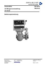
<strong>Centrifugal</strong> <strong>Gas</strong> <strong>Separator</strong><br />
<strong>Operating</strong> <strong>Manual</strong><br />
<strong>Bopp</strong> & <strong>Reuther</strong> Messtechnik GmbH<br />
Am Neuen Rheinhafen 4<br />
67346 Speyer - Germany<br />
Phone: +49 (6232) 657 - 0<br />
Fax: +49 (6232) 657 - 505<br />
www.bopp-reuther-mt.de<br />
info@bopp-reuther-mt.de<br />
Dimensions, weights and other<br />
technical data are subject to changes.<br />
Printed in the<br />
Federal Republic of Germany<br />
<strong>ZGA</strong><br />
A-EN-03661-00RevC<br />
Latest Mod. 0909-001<br />
1 of 10
<strong>ZGA</strong> <strong>Centrifugal</strong> <strong>Gas</strong> <strong>Separator</strong><br />
Table of Contents<br />
1 IDENTIFICATION...................................................................................................................................... 3<br />
1.1 SUPPLIER/MANUFACTURER 3<br />
1.2 TYPE OF PRODUCT 3<br />
1.3 NAME OF PRODUCT 3<br />
1.4 DATE OF RELEASE 3<br />
1.5 VERSION NO. 3<br />
2 AREA OF APPLICATION.......................................................................................................................... 3<br />
3 SYSTEM DESIGN ..................................................................................................................................... 3<br />
4. TECHNICAL DATA................................................................................................................................... 4<br />
4.1 OPERATING TEMPERATURE 4<br />
4.2 NOMINAL PRESSURE: 4<br />
4.3 PRESSURE DROP AND THROUGHPUT 4<br />
5 CONSTRUCTIVE DESIGN ....................................................................................................................... 4<br />
5.1 MODEL/DIMENSIONS 4<br />
5.2 WEIGHTS 6<br />
5.3 MATERIALS 7<br />
5.4 PORT AND SIGHT GLASS POSITIONS 8<br />
6 CERTIFICATES AND APPROVALS ......................................................................................................... 8<br />
7 ORDER INFORMATION ........................................................................................................................... 8<br />
8 STANDARDS AND DIRECTIVES ............................................................................................................. 8<br />
9 COMMISSIONING AND OPERATION...................................................................................................... 8<br />
10 SAFETY INFORMATION ........................................................................................................................ 9<br />
11 DISPOSAL AND DECOMMISSIONING.................................................................................................. 9<br />
12 MAINTENANCE ...................................................................................................................................... 9<br />
13 REPAIRS................................................................................................................................................. 9<br />
14 SERVICE ADDRESSES........................................................................................................................ 10<br />
Page 2 of 10 <strong>Bopp</strong> & <strong>Reuther</strong> Messtechnik GmbH
1 Identification<br />
1.1 Supplier/Manufacturer<br />
<strong>Bopp</strong> & <strong>Reuther</strong> Messtechnik GmbH<br />
1.2 Type of Product<br />
<strong>ZGA</strong> centrifugal gas separator with float-deaeration<br />
device and sight glass<br />
1.3 Name of Product<br />
<strong>ZGA</strong> <strong>Centrifugal</strong> <strong>Gas</strong> <strong>Separator</strong><br />
1.4 Date of Release<br />
September 2009<br />
1.5 Version No.<br />
03661 - 00RevC<br />
2 Area of Application<br />
In order to prevent measuring errors caused by free<br />
air or gas when using volumetric meters to<br />
measure liquid quantity, gas separators are<br />
installed in front of the meter (forward flow) for<br />
liquids with a dynamic viscosity of < 20 mPa.s (at<br />
20°C).<br />
The German weights and measures regulations<br />
(Eichordnung) specify the use of gas separators for<br />
liquids up to 20 mPas in measuring systems with<br />
pump operation which are subject to calibration.<br />
<strong>Centrifugal</strong> gas separators in connection with oval<br />
wheel meters comply with the regulations for the<br />
calibration of measuring systems in Germany and<br />
other countries.<br />
<strong>Bopp</strong> & <strong>Reuther</strong> centrifugal gas separators have<br />
EEC qualification approval and are therefore<br />
approved for EEC initial calibration.<br />
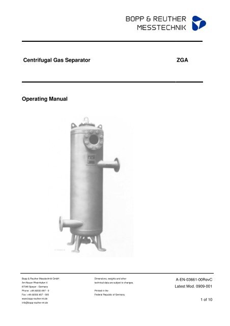
3 System Design<br />
<strong>ZGA</strong> <strong>Centrifugal</strong> <strong>Gas</strong> <strong>Separator</strong><br />
The gas separator is made of a welded pressure<br />
vessel with an integrated automatic float-deaeration<br />
device. For liquid gas measuring systems, it is also<br />
possible to use gas separators with an orifice plate<br />
installed between 2 valves in the degassing or<br />
return pipe (to the storage tank). The orifice plate is<br />
designed to allow a backflow of max. 5%. The<br />
valves are sealed in an open position. The liquid<br />
enters tangentially at the upper port, resulting in a<br />
swirling flow inside the gas separator. This swirling<br />
motion is sustained by the tangential outgoing<br />
liquid at the outlet port.<br />
The distribution of pressure in the swirling flow<br />
causes any air or gas to escape via the ventilating<br />
valve.<br />
The direction of flow is indicated by an arrow on the<br />
inlet port. The sight glass is used to monitor the<br />
float and the liquid.<br />
A sign attached to the gas separator specifically<br />
indicates two important points:<br />
• The maximum flow rate permitted by the<br />
German Board of Weights and Measures.<br />
• Only draw liquid when it is visible in the<br />
sight glass. Throttle if foam forms.<br />
Furthermore, a lead seal at the information sign is<br />
used to fix a calibration mark after measuring<br />
system calibration.<br />
The gas separator can also be equipped with a<br />
level limit switch or level indicator.<br />
<strong>Bopp</strong> & <strong>Reuther</strong> Messtechnik GmbH Page 3 of 10
<strong>ZGA</strong> <strong>Centrifugal</strong> <strong>Gas</strong> <strong>Separator</strong><br />
4. Technical Data<br />
4.1 <strong>Operating</strong> Temperature<br />
Standard: -10 to max. +100 °C<br />
Low temperature model<br />
(-140 to -10 °C) on request<br />
4.2 Nominal Pressure:<br />
PN 10, 16, 25 and 40<br />
PN 63 and 100 on request<br />
5 Constructive Design<br />
5.1 Model/Dimensions<br />
DN Inch Container<br />
25<br />
32<br />
1“<br />
1¼“<br />
capacity [ℓ]<br />
Effective<br />
volume [ℓ]<br />
Max. permissible. Dimensions and installation dimensions<br />
flow rate Q<br />
(ℓ / min)<br />
4.3 Pressure Drop and Throughput<br />
<strong>Centrifugal</strong> gas separator pressure drops<br />
depending on the flow rate and liquid viscosity.<br />
Dimensions in mm Draining port<br />
A B C D E F G H J K L M mm Inch<br />
29 10 100 75 200 460 219 ≥50 665 ~985 ~1300 13 198 480 20 -<br />
50 2“ 54 25 300 90 220 645 273 ≥50 900 ~1180 ~1500 13 220 540 20 -<br />
65 2½“ 120 60 700 120 290 840 368 ≥80 1100 ~1385 ~1600 13 280 650 20 -<br />
80 3“ 180 95 1200 150 350 1030 419 ≥50 1330 ~1625 ~1900 20 360 750 0 32 1 ¼“<br />
100 4“ 180 95 1200 130 380 1060 419 ≥50 1360 ~1655 ~1930 20 360 750 - 32 1 ¼“<br />
100 4“ 300 180 2000 170 400 1250 500 ≥70 1520 ~1885 ~2200 20 440 850 - 32 1 ¼“<br />
100 4“ 470 295 3000 200 400 1530 559 ≥60 1780 ~2100 ~2400 20 440 850 - 32 1 ¼“<br />
150 6“ 470 295 3000 180 420 1530 559 ≥60 1780 ~2100 ~2400 20 440 850 - 32 1 ¼“<br />
150 6“ 1000 675 5000 285 600 1800 800 ≥135 2125 ~2500 ~2800 35 660 1150 - 40 1 ½“<br />
200 8“ 1000 675 5000 260 600 1800 800 ≥135 2125 ~2500 ~2800 35 660 1200 - 40 1 ½“<br />
250 10“ 1000 675 5000 235 600 1800 800 ≥135 2125 ~2500 ~2800 35 660 1300 - 40 1 ½“<br />
200 8“ 2200 1500 10000 385 750 2250 1050 ≥170 2725 ~3180 ~3500 35 880 1500 - 50 2 “<br />
250 10“ 2200 1500 10000 325 750 2250 1050 ≥170 2725 ~3180 ~3500 35 880 1500 - 50 2 “<br />
300 12“ 2200 1500 10000 300 750 2250 1050 ≥170 2725 ~3180 ~3500 35 880 1600 - 50 2 “<br />
300 12“ 2700 1900 12000 360 865 2465 1150 ≥200 2785 ~3325 ~3700 35 880 1700 - 50 2 “<br />
300 12“ 5000 2800 20000 500 900 2600 1500 ≥240 2965 ~3670 ~3990 35 1140 1900 - 80 3 “<br />
400 16“ 5000 2800 20000 450 950 2650 1500 ≥240 2965 ~3670 ~3990 35 1140 1900 - 80 3 “<br />
300 12“ 7000 5000 25000 550 1000 3200 1600 ≥250 4580 ~5300 5700 35 1250 2200 - 100 4 “<br />
400 16“ 7000 5000 25000 500 1000 3200 1600 ≥250 4580 ~5300 5700 75 1250 2200 - 100 4 “<br />
Page 4 of 10 <strong>Bopp</strong> & <strong>Reuther</strong> Messtechnik GmbH<br />
DN<br />
ISO<br />
228-G ½<br />
(or ½ - 14<br />
NPT)
DN 25 - DN 65<br />
DN 80 - DN 400<br />
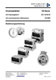
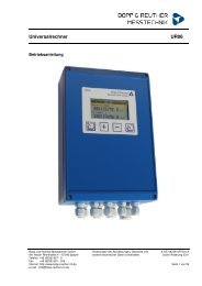
1 Draining port ISO 228 – G 1/2 (or ½ - 14 NPT)<br />
<strong>ZGA</strong> <strong>Centrifugal</strong> <strong>Gas</strong> <strong>Separator</strong><br />
2 Deaeration connection ISO 228 – G 1 A (or 1 – 11 ½ NPT)<br />
3 Sight glass<br />
4 Inlet port<br />
5 Outlet port<br />
6 Manufacturer and information sign with details and calibration seal of<br />
the German Board of Weights and Measures.<br />
H Valve expansion height<br />
Port and sight glass position, sketch of model a 1 (see 5.4)<br />
with deaeration device<br />
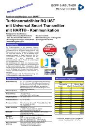
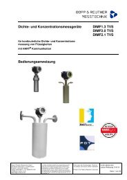
1 Draining port<br />
2 Deaeration connection ISO 228 – G 1 A (or 1 – 11 ½ NPT)<br />
3 Sight glass<br />
4 Inlet port<br />
5 Outlet port<br />
6 Manufacturer and information sign with details and calibration seal of the<br />
German Board of Weights and Measures<br />
H Valve expansion height<br />
Cover design for DN 65<br />
Port and sight glass position, sketch of model a 1 (see 5.4)<br />
<strong>Bopp</strong> & <strong>Reuther</strong> Messtechnik GmbH Page 5 of 10
<strong>ZGA</strong> <strong>Centrifugal</strong> <strong>Gas</strong> <strong>Separator</strong><br />
5.2 Weights<br />
Nominal size<br />
DN<br />
Container<br />
capacity<br />
[ℓ]<br />
Effective Max. permissible<br />
volume<br />
[ℓ]<br />
Flow rate Q<br />
[ℓ/min]<br />
Weight [kg]<br />
PN 10 PN 16 PN 25 PN 40<br />
25 29 10 100 78 78 100 10<br />
32 29 10 100 78 78 100 100<br />
50 45 25 300 120 120 160 160<br />
65 120 60 700 145 145 170 170<br />
80 180 95 1200 165 165 210 210<br />
100 180 95 1200 170 170 220 220<br />
100 300 180 2000 220 220 260 300<br />
100 470 295 3000 250 250 360 520<br />
150 470 295 3000 250 250 360 520<br />
150 1000 675 5000 420 520 730 860<br />
200 1000 675 5000 420 520 730 860<br />
250 1000 675 5000 420 520 730 860<br />
200 2200 1500 10000 850 1100 1450 2280<br />
250 2200 1500 10000 850 1100 1450 2280<br />
300 2200 1500 10000 850 1100 1450 2280<br />
300 2700 1900 12000 1080 1375 1880 2900<br />
300 5000 2800 20000 1 ) 1800 2200 2700 4300<br />
400 5000 2800 20000 1 ) 1800 2200 2700 4300<br />
300 7000 5000 25000 1 ) 2400 3050 3500 6050<br />
400 7000 5000 25000 1 ) 2400 3050 3500 6050<br />
1) with 2 deaeration devices<br />
Page 6 of 10 <strong>Bopp</strong> & <strong>Reuther</strong> Messtechnik GmbH
5.3 Materials<br />
Material Model A Model F<br />
Casing:<br />
Wear allowance:<br />
Floor:<br />
Ports:<br />
Flanges:<br />
Cover and<br />
welding flange:<br />
P265 GH (HII)<br />
C2 = 1 mm (for wall thickness < 30 mm)<br />
P265 GH (HII)<br />
P235 GH (ST 35.8 I)<br />
According to DIN C 22.8 1 )<br />
According to ANSI C 21 (A105 1 )<br />
<strong>ZGA</strong> <strong>Centrifugal</strong> <strong>Gas</strong> <strong>Separator</strong><br />
<strong>Bopp</strong> & <strong>Reuther</strong> Messtechnik GmbH Page 7 of 10<br />
-<br />
1.4571 1 )<br />
1.4571 1 )<br />
1.4571 1 )<br />
1.4571 1 )<br />
P265 GH (HII) 1.4571 1 )<br />
Bolts: C 35 E according to DIN 931 or 938 1.4751 1 ) according to DIN 931 or 938<br />
Nuts:<br />
<strong>Gas</strong>kets:<br />
Welding:<br />
Welding process:<br />
Welding Consumables:<br />
C 35 according to DIN EN 24032<br />
Novapress-Multi/Viton<br />
Electrofusion welding<br />
Root run: 141 (WIG)<br />
Filler run: 111 (TIG /GTAW), 135 (MAG)<br />
Final run: 111 (TIG/GTAW)<br />
141 (WIG) EN 1668 – W2Mo<br />
111 (TIG/GTAW) DIN EN 499 –<br />
E420RR12<br />
135 (MAG) EN 440 – G 46 2 C G4 Si 1<br />
Deaeration device: Cast brass/steel and chrome nickel steel<br />
1.4571<br />
1) Acceptance test certificate 3.1 B according to DIN EN 10204<br />
1.4571 1 ) according to DIN EN 24032<br />
Teflon<br />
Electrofusion welding<br />
Root run: 141 (WIG)<br />
Filler run: 111 (TIG /GTAW), 135 (MAG)<br />
141 (WIG)<br />
Final run: 111 (TIG/GTAW), 141 (WIG)<br />
141 (WIG) prEN 12072 – W 19 12 3 L Si<br />
111 (TIG/GTAW) EN 1600 – E 19 12 3 LR 32<br />
135 (MAG) 9rEN 12072 – G 19 12 3 L Si<br />
Chrome nickel steel<br />
1.4408 and 1.4571<br />
Deviations to normal A and F models as well as devices calculated and tested according to other<br />
construction regulations: On request.
<strong>ZGA</strong> <strong>Centrifugal</strong> <strong>Gas</strong> <strong>Separator</strong><br />
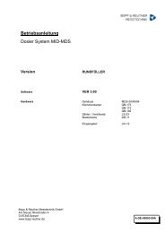
5.4 Port and Sight Glass Positions<br />
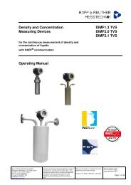
Fig. 3 Port and sight glass positions of the<br />
centrifugal gas separator DN 25 - 400<br />
E Inlet port<br />
A Outlet port<br />
S Sight glass<br />
The arrows indicate the direction of flow. The inlet<br />
port E is always at the top, the outlet port A at the<br />
bottom.<br />
6 Certificates and Approvals<br />
EEC Approval: D82 5.151.03. Manufactured by a<br />
welding specialist with HP0 approval<br />
(TRB200/TRD201) and TÜV (German Technical<br />
Inspection Authority) approval for welding quality<br />
requirements according to DIN-EN 729-2.<br />
7 Order Information<br />
When ordering please state:<br />
The product data, especially weight, temperature,<br />
pressure, viscosity, material, connection sizes,<br />
measuring range, desired accessories, required<br />
approvals, certificates and material certificates.<br />
See device selection according to model code.<br />
8 Standards and Directives<br />
• Designed and manufactured according to AD<br />
2000 directives.<br />
• Interpretation of measuring ranges and<br />
conversion of values should conform to VDE<br />
VDI 3513 directives.<br />
• Explosion protection directive 94/9/EC:<br />
The device complies with the standards<br />
EN1127-1 and EN13463-1 in accordance with<br />
ATEX100a. The operator should always<br />
observe respective regulations when installing<br />
and connecting the device in explosive areas.<br />
• Pressure equipment directive 97/23/EC:<br />
<strong>ZGA</strong> centrifugal gas separators are suitable for<br />
group 1 liquids.<br />
Classification generally within Category IV, with<br />
individual acceptance acc. to Module G of the<br />
pressure equipment device directive.<br />
9 Commissioning and Operation<br />
The gas separator should be connected to the<br />
process via the flanges (please observe the<br />
direction of flow!!). Depending on the application,<br />
the same applies for deaerating and draining<br />
connections. The gas separator has to be<br />
connected to earth via an earthing strap fixed to<br />
one of the feet. This ensures that the gas separator<br />
is included in the system’s equipotential bonding.<br />
Caution!<br />
Release the transportation lock at the float ball<br />
prior to commissioning. To achieve this,<br />
remove the housing cover with the device and<br />
subsequently retighten it carefully.<br />
The entire measuring system and pipework are<br />
deaerated via the ventilating valve during start-up.<br />
Page 8 of 10 <strong>Bopp</strong> & <strong>Reuther</strong> Messtechnik GmbH
10 Safety Information<br />
The centrifugal gas separator should only be used<br />
for its intended area of application (see 2). Always<br />
observe the pressure and temperature limits stated<br />
on the type plate as well as all other technical data<br />
and safety information during device installation,<br />
commissioning and operation.<br />
Always observe national and international<br />
regulations concerning the operation of devices<br />
and systems under pressure.<br />
Prior to installation, the operator has to ensure that<br />
the pressure bearing parts have not been damaged<br />
during transportation.<br />
The devices have to be installed, operated and<br />
serviced by qualified personnel. The operator has<br />
the responsibility to ensure that the personnel have<br />
received sufficient and appropriate training. In<br />
cause of doubt, please contact the manufacturer.<br />
Only measure liquids to which the materials of the<br />
pressure bearing elements are resistant.<br />
Only release flanges, connections for deaerating or<br />
draining purposes, or the sight glass when the<br />
devices are depressurised.<br />
Only use the original spare parts specified by the<br />
manufacturer when replacing components. In the<br />
case of non-compliance, warranty shall not apply.<br />
Carefully select gaskets or sealing elements<br />
according to the operating instruction specifications<br />
(see 5.3).<br />
<strong>ZGA</strong> <strong>Centrifugal</strong> <strong>Gas</strong> <strong>Separator</strong><br />
Type plate with pressure-relevant information<br />
The used abbreviations have the following<br />
meaning:<br />
Serial number: Clear identification no.<br />
Year: Year of construction<br />
PT: Achieved test pressure, and test<br />
<strong>Bopp</strong> & <strong>Reuther</strong> Messtechnik GmbH Page 9 of 10<br />
date<br />
DN: Nominal width<br />
Capacity: Container capacity in litres<br />
TS: Permissible operating temperature<br />
PS: Permissible excess operating<br />
pressure<br />
11 Disposal and Decommissioning<br />
Disposal or decommissioning should only be<br />
carried out by qualified personnel. Product residue<br />
has to be disposed of in accordance with legal<br />
regulations.<br />
12 Maintenance<br />
The centrifugal gas separator is maintenance-free.<br />
13 Repairs<br />
This device has been designed, produced and<br />
tested with the utmost care. In the unlikely event<br />
that a fault should occur, please contact our service<br />
department.
14 Service Addresses<br />
<strong>Bopp</strong> & <strong>Reuther</strong> Messtechnik GmbH<br />
Service<br />
Am Neuen Rheinhafen 4<br />
D-67346 Speyer<br />
Phone: +49 (6232) 657-402<br />
Fax: +49 (6232) 657 561<br />
<strong>Bopp</strong> & <strong>Reuther</strong> Messtechnik GmbH<br />
Am Neuen Rheinhafen 4<br />
67346 Speyer - Germany<br />
Phone: +49 (6232) 657 - 0<br />
Fax: +49 (6232) 657 - 505<br />
www.bopp-reuther-mt.de<br />
info@bopp-reuther-mt.de<br />
Dimensions, weights and other<br />
technical data are subject to changes.<br />
Printed in the<br />
Federal Republic of Germany<br />
<strong>Bopp</strong> & <strong>Reuther</strong> Messtechnik GmbH<br />
Münchener Str. 23<br />
D-85123 Karlskron<br />
Industrial Estate Brautlach, on the B 13<br />
Phone: +49 (8450) 928330<br />
Fax: +49 (8450) 928332<br />
A-EN-03661-00RevC<br />
Latest Mod. 0909-001<br />
10 of 10