Smartline Autosampler 3900 Manual / Handbuch V 1508 03/2007
Smartline Autosampler 3900 Manual / Handbuch V 1508 03/2007
Smartline Autosampler 3900 Manual / Handbuch V 1508 03/2007

You also want an ePaper? Increase the reach of your titles
YUMPU automatically turns print PDFs into web optimized ePapers that Google loves.
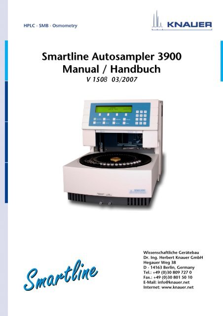
<strong>Smartline</strong> <strong>Autosampler</strong> <strong>3900</strong><br />
<strong>Manual</strong> / <strong>Handbuch</strong><br />
V <strong>1508</strong> <strong>03</strong>/<strong>2007</strong><br />
Wissenschaftliche Gerätebau<br />
Dr. Ing. Herbert Knauer GmbH<br />
Hegauer Weg 38<br />
D - 14163 Berlin, Germany<br />
Tel.: +49 (0)30 809 727 0<br />
Fax.: +49 (0)30 801 50 10<br />
E-Mail: info@knauer.net<br />
Internet: www.knauer.net
CONTENTS<br />
Using this <strong>Manual</strong> 5<br />
Conventions in this <strong>Manual</strong> 5<br />
Quick Start AS <strong>3900</strong> 5<br />
Programming Chart 10<br />
About AS <strong>3900</strong> 11<br />
Instrument Description 13<br />
Injection Principle 14<br />
Full loop injections 15<br />
Partial loop fill injections 16<br />
µl Pick-up injections 18<br />
Installation 20<br />
Unpacking 20<br />
Location of AS <strong>3900</strong> 21<br />
Power connections 21<br />
Fluid connections 22<br />
HPLC connections 23<br />
Waste tubing 23<br />
Wash solvent and System rinse 23<br />
Syringe 24<br />
Preparation of vials 24<br />
Vial dimensions 24<br />
Filling and sealing the vials 26<br />
Loading the sample tray 27<br />
Control I/O connections. 27<br />
Contact closure output connector (P1): 27<br />
TTL input connector (P2): 27<br />
Multi Link Connector 29<br />
Operation 30<br />
Typographic convention 30<br />
How to use the keyboard 30<br />
Hard function keys 31<br />
Direct functions 31<br />
Direct Control functions: 32<br />
32<br />
System Settings 34<br />
General System Settings 35<br />
Method System Settings 36<br />
Tray Settings 36<br />
I/O configuration 37<br />
Serial Communication 37<br />
Prep Mode System Settings 37<br />
Method programming 38<br />
Injection program 38<br />
Wash program 39<br />
Timed events program 40<br />
Mix program 42<br />
Programming the Run sequence; Series 43<br />
Running 45<br />
Start and Stop 45<br />
Remote control 45<br />
Priority sample 46<br />
Programming during Run 47
2<br />
Maintenance 47<br />
Injection valve 47<br />
Replacing the injection valve 47<br />
Valco Cheminert ® Module C2 Valve 48<br />
Operating Instructions for Rheodyne Model 7739 Valve 49<br />
Operating Instructions for Rheodyne Model 9740 Valve 50<br />
Needle and tubing 52<br />
Sample needle 54<br />
Air needle replacement 55<br />
Sample needle penetration depth 55<br />
Syringe 55<br />
Troubleshooting 57<br />
Start up problems 57<br />
Analytical problems 58<br />
Quick check! 58<br />
No injection 59<br />
Bad reproducibility 60<br />
APPENDIX A: List of Accessories 61<br />
APPENDIX B: Error Codes 63<br />
APPENDIX C: Test Procedure 65<br />
APPENDIX D: AS <strong>3900</strong>, Preparative 73<br />
Specifications AS <strong>3900</strong>, prep 73<br />
Installation AS <strong>3900</strong>, prep 74<br />
Injecting with the AS <strong>3900</strong>, prep 75<br />
Firmware replacement 75<br />
Technical Data 77<br />
Declaration of conformity 152<br />
Guarantee statement 153<br />
INDEX 154
INHALT<br />
Hinweise zum Gebrauch des <strong>Handbuch</strong>s 78<br />
Konventionen in diesem <strong>Handbuch</strong> 78<br />
Schnellstart des AS <strong>3900</strong> 79<br />
Programmübersicht 84<br />
AS <strong>3900</strong>, allgemeine Beschreibung 85<br />
Instrumentbeschreibung 87<br />
Injektionsprinzip 88<br />
Vollschleifeninjektion 89<br />
Partielle Schleifenfüllung 91<br />
µl Pick-up Injektionen 92<br />
Installation 94<br />
Auspacken 94<br />
Aufstellung des AS <strong>3900</strong> 95<br />
Netzanschluss 95<br />
Kapillar- und Schlauchanschlüsse 96<br />
HPLC Kapillaranschlüsse 97<br />
Abfallleitungen 97<br />
Waschlösung und Systemspülung 97<br />
Spritze 98<br />
Vorbereitung der Vials 98<br />
Vialdimensionen 98<br />
Füllen und Verschließen der Vials 100<br />
Beschickung des Probentellers 101<br />
Steueranschlüsse I/O 101<br />
Kurzschlussausgangsanschluss (P1): 101<br />
TTL Eingangsanschluss (P2) 101<br />
Multi Link Anschlüsse 1<strong>03</strong><br />
Betrieb 104<br />
Typographische Festlegungen 104<br />
Benutzung der Tastatur 104<br />
Feste Funktionstasten 105<br />
Direktfunktionen 105<br />
Direkte Steuerfunktionen: 106<br />
Systemeinstellungen 108<br />
Allgemeine Einstellungen 109<br />
Methodeneinstellungen 110<br />
Probentellereinstellungen 110<br />
I/O Konfiguration 111<br />
Serielle Kommunikation 111<br />
Prep-Modus Einstellungen 111<br />
Methodenprogrammierung 112<br />
Injektionsprogramm 113<br />
Waschprogramm 114<br />
Ereignisprogramm (Timed events program) 114<br />
Mischprogramm 116<br />
Programmierung der Runsequenz; Serie 117<br />
Betrieb 119<br />
Start und Stopp 119<br />
Fernsteuerung 120<br />
Probenpriorität 120<br />
Programmierung während des Laufs 121<br />
3
4<br />
Wartung 121<br />
Injektionsventil 121<br />
Austausch des Injektionsventils 121<br />
Valco Cheminert ® Module C2 Ventil 122<br />
Bedienungsanleitung für das Rheodyne Ventil Modell 7739 123<br />
Bedienungsanleitung für das Rheodyne Ventil 9740 125<br />
Nadel und Schlauchverbindung 126<br />
Probennadel 128<br />
Luftnadelaustausch 129<br />
Eindringtiefe der Probennadel 129<br />
Spritzenwechsel 129<br />
Troubleshooting 131<br />
Startprobleme 131<br />
Analytische Probleme 132<br />
Schnelltest 132<br />
Keine Injektion 133<br />
Schlechte Reproduzierbarkeit 134<br />
ANHANG A: Zubehör 135<br />
ANHANG B: Fehlermeldungen 137<br />
ANHANG C: Test Prozeduren 139<br />
ANHANG D: AS <strong>3900</strong>, Prep 147<br />
Spezifikationen des AS <strong>3900</strong>, prep 147<br />
Installation des AS <strong>3900</strong>, prep 148<br />
Injektionen mit dem AS <strong>3900</strong>, prep 148<br />
Firmwareaustausch 149<br />
Technische Daten 151<br />
Gewährleistungsbedingungen 152<br />
Konformitätserklärung 153<br />
INDEX 156
Using this <strong>Manual</strong> 5<br />
Using this <strong>Manual</strong><br />
Conventions in this <strong>Manual</strong><br />
Special Warnings are indicated by the marginal warning sign and<br />
printed in bold letters.<br />
The marginal lamp symbol indicates helpful advice.<br />
Important Hints are marked by the marginal hand symbol.<br />
Arrows in an outlined form like this example used in block diagrams<br />
indicate an automatic program run and change to the next line without the<br />
necessity of manual interventions.<br />
Arrows like this, used in block diagrams, indicate that the user is asked to<br />
press the corresponding arrow keys<br />
� � � � The triangles symbolize the use of corresponding arrow keys.<br />
Quick Start AS <strong>3900</strong><br />
This section of the manual is written, to make a quick start with your<br />
autosampler AS <strong>3900</strong>. Step by step from installation through running<br />
complete analysis. It makes AS <strong>3900</strong> your companion in the lab in a<br />
minimum of time.<br />
Installation<br />
(For more detailed information, See page 20 of this manual)<br />
• Allow the AS <strong>3900</strong> to adopt ambient temperature for at least one<br />
hour<br />
• Check AS <strong>3900</strong> for visual damages due to transport, if this is the<br />
case, please contact your distributor immediately.<br />
• Remove the safety screw on the right-hand side of the front cover.<br />
Keep the keyboard front cover closed during operation.<br />
• Check fuses and voltage settings on the rear side of the<br />
instrument.<br />
• Connect the power cable
6 Quick Start AS <strong>3900</strong><br />
• After turning "ON" the power, the Ready screen appears displaying<br />
the firmware revision number.<br />
• Connect the drain tubing to the wash outlet on the lower front side<br />
of the instrument.<br />
• Fill the wash solvent bottle with distilled water/ 2-Propanol (80/20<br />
v/v%) or mobile phase. Only water/organic solvents should be<br />
used. Do not use any crystalline or buffer solutions; these may<br />
block the system and cause severe damages. To avoid air bubbles<br />
in the syringe degas the wash solvent.<br />
• Fill the wash solvent tubing, syringe and buffer tubing by washing<br />
the system 2 or 3 times. This is done by pressing the soft<br />
function key from the Ready screen. Check if there are some air<br />
bubbles trapped in the syringe, they can be removed by gently<br />
ticking to the syringe.<br />
• Connect your HPLC pump to port 1 of the injection valve and the<br />
column (or capillary) to port 6 of the injection valve. Check for<br />
leakage and let the system equilibrate for at least 5 minutes.<br />
System settings (See page 34 of this manual)<br />
Normally these settings are correctly installed, to check and set these<br />
(standard) settings, proceed as follows:<br />
Press keys: Description:<br />
[System] Enter the System Settings<br />
Enter the General Settings<br />
[0100] [Enter] Volume of installed loop: 100 µl.<br />
[015] [Enter] Volume of tubing needle ↔ valve:015 µl<br />
[Enter] Syringe volume: 250 µl<br />
[Enter] Set Syringe speed to Normal.<br />
[Enter] Skip missing vials.<br />
[Enter] Air segment: use air segment<br />
[Enter] Headspace pressure: On<br />
Press [Escape] twice to go back to the Ready screen<br />
Example 1: Performing a 10 µl partial loop fill injection from vial number 1.<br />
Performing injection routines is easy with AS <strong>3900</strong>. First you define a<br />
method such as the injection, mix or wash method. These methods are<br />
stored in battery back up. Subsequently a Run sequence or Series can<br />
be programmed in which those methods are linked to the Series of vials.<br />
AS <strong>3900</strong> will eventually execute those Series.<br />
Programming the method (See page 38 of this manual)<br />
Injection Program:<br />
Press keys: Description:<br />
[Methods] [1] [Enter] Enter Method number 1.<br />
Selecting partial loop fill injection<br />
[Enter]<br />
program<br />
[30] [Enter] Flush volume: e.g. 30 µl<br />
[1] [Enter] Number of injections per vial: 1<br />
[10] [Enter] Injection volume: 10 µl<br />
[100] [Enter] Enter the analysis time e.g. 1 minute<br />
Press [Escape] once to go up one level.<br />
Wash Program:<br />
Press keys: Description:<br />
Selecting wash program<br />
Disable the wash<br />
Press [Escape] three times to go back to the Ready screen.
Quick Start AS <strong>3900</strong> 7<br />
Programming the Series (See page 43 of this manual)<br />
Press keys: Description:<br />
[Series] [1] [Enter] Enter Series number 1.<br />
[1] [Enter] Enter Method number:1<br />
[1] [Enter] Enter First sample vial: 01<br />
[1] [Enter] Enter Last sample vial: 01<br />
Press [Escape] (twice) to go back to the Ready screen<br />
Running the Series (See page 45 of this manual)<br />
Put a sample vial in position 1. (If you can’t reach position 1, turn the tray<br />
manually).<br />
Press keys: Description:<br />
[Start/Stop]<br />
[1] [Enter] Start at Series number:1<br />
[1] [Enter] Stop after Series number: 01<br />
If you press AS <strong>3900</strong> will start searching for vial 1 and perform<br />
a 10 µl injection.<br />
EXAMPLE 2: Performing three 10 µl injections from one vial without sample loss<br />
using the µl Pick-up injection routine, followed by a wash routine<br />
between each injection.<br />
If the Air segment is set ON in System Settings, a small air segment<br />
will also be injected into your HPLC system (For more detailed<br />
information, See page 45 of this manual).<br />
For switching OFF the air segment enter the System Settings and change<br />
the setting for the air segment: from YES to NO.<br />
This is done by pressing<br />
[System] [Enter] [Enter] [Enter] [Enter] [Enter] <br />
[Escape] [Escape]<br />
Programming the method (See page 38 of this manual)<br />
Injection program:<br />
Press keys: Description:<br />
[Methods] [1] [Enter] Enter Method number 1.<br />
<br />
[Enter]<br />
Selecting µl pick-up injection program<br />
[3] [Enter] Number of injections per vial: 3<br />
[10] [Enter] Injection volume: 10 µl<br />
[100] [Enter] Enter the analysis time e.g. 1 minute<br />
Press [Escape] once to go up one level.<br />
Wash Program:<br />
Press keys: Description:<br />
Selecting wash program<br />
[ENTER} Perform a wash after each injection<br />
[1] [Enter] Enter the number of syringe volumes to be<br />
used for washing, e.g. 1 syringe volume.<br />
Press [Escape] three times to go back to the Ready screen.<br />
Programming the Series (See page 43 of this manual)<br />
Press keys: Description:<br />
[Series] [1] [Enter] Enter Series number 1.
8 Quick Start AS <strong>3900</strong><br />
Press keys: Description:<br />
[1] [Enter] Enter Method number:1<br />
[1] [Enter] Enter First sample vial: 01<br />
[1] [Enter] Enter Last sample vial: 01<br />
Press [Escape] (twice) to go back to the Ready screen<br />
Running the Series (See page 45 of this manual)<br />
Put a sample vial in position 1 and a vial with transport solvent (mobile<br />
phase) in position 85.<br />
Be sure the transport vial is filled correctly before starting a new<br />
Series.<br />
Press keys: Description:<br />
[Start/Stop]<br />
[1] [Enter] Start at Series number:1<br />
[1] [Enter] Stop after Series number: 1<br />
If you press AS <strong>3900</strong> will start searching for the transport vial<br />
and perform 3 injections of 10 µl. After every injection the needle system<br />
will be washed with 1 syringe volume.<br />
EXAMPLE 3: Performing a 1:10 dilution followed by a 10 µl partial loop fill<br />
injection<br />
The mix method will perform the following:<br />
Transfer 360 µl from Reagent A to the destination vial, add 40 µl sample,<br />
mix 3 times with 250 µl and subsequently inject 10 µl.<br />
From the Ready screen:<br />
Programming the method (See page 38 of this manual)<br />
Injection Program:<br />
Press keys: Description:<br />
[Methods] [1] [Enter] Enter Method number 1.<br />
Selecting partial loop fill injection program<br />
[Enter]<br />
[30] [Enter] Flush volume: e.g. 30 µl<br />
[1] [Enter] Number of injections per vial: 1<br />
[10] [Enter] Injection volume: 10 µl<br />
[100] [Enter] Enter the analysis time e.g. 1 minute<br />
Press [Escape] once to go up one level.<br />
Wash Program:<br />
Press keys: Description:<br />
Selecting Wash program<br />
Disable the wash<br />
Press [Escape] once to go up one level.<br />
Mix Program: (See page 42 of this manual)<br />
Press keys: Description:<br />
Selecting Mix program<br />
Confirm the use of the Mix program<br />
<br />
[180] [Enter]<br />
[Enter]<br />
<br />
[Enter]<br />
Insert the first Mix step:<br />
Add 180 µl Reagent–A to the Destination<br />
vial.<br />
Insert the second Mix step:
Quick Start AS <strong>3900</strong> 9<br />
Press keys: Description:<br />
[180] [Enter]<br />
[Enter]<br />
<br />
[Enter]<br />
<br />
[40] [Enter]<br />
[Enter]<br />
<br />
[Enter]<br />
<br />
[3] [Enter]<br />
[250] [Enter]<br />
Add another 180 µl Reagent–A to the<br />
Destination vial.<br />
Insert the third Mix step:<br />
Add 40 µl from the Sample vial to the<br />
Destination vial.<br />
Insert the fourth Mix step:<br />
Mix the contents of the Destination vial 3<br />
times with a volume of 250 µl<br />
Press [Escape] three times to go back to the Ready screen<br />
Programming the Series (See page 43 of this manual)<br />
Press keys: Description:<br />
[Series] [1] [Enter] Enter Series number 1.<br />
[1] [Enter] Enter Method number:1<br />
[1] [Enter] Enter First sample vial: 01<br />
[1] [Enter] Enter Last sample vial: 01<br />
[2] [Enter] Enter First destination vial: 02<br />
Press [Escape] (twice) to go back to the Ready screen<br />
Running the Series (See page 45 of this manual)<br />
Put a sample vial in position 1, an empty sealed destination vial in<br />
position 2 and a filled reagent vial in position 86. Be sure the reagent vial<br />
is filled correctly before starting a new Series. (If you can’t reach one of<br />
the tray positions, turn the tray manually).<br />
Press keys: Description:<br />
[Start/Stop]<br />
[1] [Enter] Start at Series number:1<br />
[1] [Enter] Stop after Series number: 1<br />
If you press AS <strong>3900</strong> will start searching for vial 86 and<br />
transport 180 µl to the destination vial twice, subsequently 40 µl of<br />
sample will be added and after mixing 3 times a 10 µl injection will be<br />
performed.
10 Programming Chart<br />
Programming Chart<br />
[System]<br />
[Methods]<br />
[Series]<br />
[Start/Stop]<br />
[Priority]<br />
[Hold/Cont.]<br />
Ready screen<br />
<br />
Perform<br />
standard<br />
wash<br />
Maintenance<br />
functions.<br />
System Settings<br />
1<br />
Copy<br />
methods<br />
Erase<br />
methods<br />
Midas<br />
logbook<br />
Serial<br />
communication<br />
protocol<br />
Control<br />
column oven<br />
temperature<br />
Control<br />
sample tray<br />
cooling<br />
<br />
Loop volume<br />
Needle volume<br />
Syringe volume<br />
Syringe speed<br />
Skip missing vials<br />
Air segment<br />
Headspace pressure<br />
Use calibration<br />
vials<br />
Method programming<br />
Tray type Inject marker pulse length<br />
Input edge next injection<br />
Freeze input active<br />
Reset outputs after last<br />
Series<br />
Service<br />
mode<br />
Device identifier Select Prep mode 2<br />
<br />
Injection type:<br />
<br />
Flush volume<br />
No injections/vial<br />
Analysis time<br />
Flush volume<br />
No injections/vial<br />
Injection volume<br />
Analysis time<br />
Method number<br />
First sample vial<br />
Last sample vial<br />
Use calibration vials 3<br />
First calibration vial<br />
Last calibration vial<br />
Vials between calibration<br />
First destination vial 4<br />
First Series<br />
Last Series<br />
<br />
Sample vial<br />
Hold the analysis time of the Midas<br />
Fig. 1 Programming chart<br />
No injections/vial<br />
Injection volume<br />
Analysis time<br />
Wash volume Timed events program: Mix program:<br />
Wash between:<br />
- Series<br />
- Vials<br />
- Series<br />
- 4 x AUX-1<br />
- 4 x AUX-2<br />
- INITIAL OVEN SETPOINT<br />
- 2 x OVEN SETPOINT<br />
- END TIME<br />
1. Available when the optional tray cooling is installed.<br />
2. When selecting the Prep mode, some system settings are no longer programmable, but set to a fixed value.<br />
3. Depends on the System Settings.<br />
4. In case Destination vials are used in the mix of the method.<br />
- Add<br />
- Mix<br />
- Wait
About AS <strong>3900</strong> 11<br />
About AS <strong>3900</strong><br />
AS <strong>3900</strong> has been designed to meet the challenge of the modern<br />
analytical laboratory: robust, cost-effective and easy to implement.<br />
Column temperature control and sample cooling are available for<br />
consistent results. High-resolution syringe control guarantees superior<br />
precision for injection and reagent addition. And, for quick service, the<br />
entire injection valve can be replaced in seconds! The use of these and<br />
many more features is described in this manual to help you exploit the full<br />
potential of AS <strong>3900</strong>.<br />
PASA, a robust injection concept.<br />
Loop injection with Pressure Assisted Sample Aspiration (PASA) is a<br />
proven concept that combines high precision with simplicity and reliability.<br />
No moving around with the sample needle. Reduced risk for bubbles in<br />
the sample line. No needle port that wears and contaminates. There is<br />
only intelligent valve switching and highly accurate syringe control. Yet,<br />
three injection modes can be selected: full loop, partial loop filling and µl<br />
Pick-up for maximum precision, maximum flexibility and zero sample<br />
loss.<br />
Fig. 2 The PASA injection concept.<br />
Air pressure
12 About AS <strong>3900</strong><br />
Side-port needle: a good point!<br />
The strong side-port needle combines the optimum point style for piercing<br />
with a minimum risk of blockage by septum particles. For small sample<br />
volumes, a spring-loaded needle is available for maximum sample<br />
aspiration independent of variations in vial dimensions.<br />
Column oven for consistent results.<br />
A column oven is an integral part of AS <strong>3900</strong>, because constant column<br />
temperature is important for long term stability of a chromatographic<br />
separation and may be required by GLP directives.<br />
Integrated sample cooling option.<br />
Thermo-electric sample cooling is available as a fully integrated option.<br />
No external device is required and the efficient cooling concept does not<br />
restrict access to the sample tray during operation.<br />
Reagent addition made simple.<br />
Internal Standard addition, sample dilution or derivatization can be<br />
programmed in a very simple manner. A single-stage derivatization of a<br />
sample in a separate (destination) vial requires no more than 4 program<br />
lines. Multi-reagent addition is also possible: two large volume reagent<br />
vials are available on the sample tray.<br />
PC-based control.<br />
For communication with external computers, a serial interface and<br />
<strong>Smartline</strong> communication protocol are standard. A Microsoft® Windows<br />
based software package for AS <strong>3900</strong> control from a PC greatly improves<br />
operation and programming convenience and extends programming<br />
capabilities. A printout of all relevant system parameters is another<br />
valuable plus when using PC control. The Microsoft® Windows<br />
package will become available by the end of 1996.<br />
Service friendly design.<br />
Low instrument down time is accomplished by a high mean time between<br />
failure and quick instrument service. Special attention has been paid to<br />
these aspects of the concept, as is illustrated by the injection valve: AS<br />
<strong>3900</strong> will alert you in case the lifetime of the seal is exceeded or if the<br />
switching torque becomes too high. This allows preventive maintenance<br />
before injection performance degrades. And if necessary, the entire<br />
injection valve can be replaced in seconds with the unique Quick-fit valve<br />
mounting mechanism.
Instrument Description 13<br />
Instrument Description<br />
8<br />
10<br />
9<br />
7<br />
12<br />
11<br />
Fig. 3 autosampler AS <strong>3900</strong> exploded view.<br />
13<br />
1. Needle arm.<br />
2. Injection valve.<br />
3. Oven compartment.<br />
4. Tubing guide.<br />
5. Wash position.<br />
6. Position for transport solvent<br />
and reagent vials.<br />
6<br />
5<br />
7. Wash and waste drain.<br />
8. Condensed water and<br />
leakage drain<br />
9. Tray fixation knob.<br />
10. Sample tray.<br />
11. Syringe dispenser.<br />
12. Keyboard.<br />
13. Buffer tubing.<br />
Placing the sample tray in the AS <strong>3900</strong>:<br />
• Place the sample tray in the AS <strong>3900</strong> and rotate it till<br />
sinks into the slot, only one position possible.<br />
• Turn the tray fixation knob (9) clock-wise to fixate the<br />
tray.<br />
• The AS <strong>3900</strong> is now ready for use.<br />
1<br />
4<br />
3<br />
2
14 Injection Principle<br />
1. P2- I/O connector; Inputs, see page 27.<br />
2. P1- I/O connector; Relays outputs.<br />
3. Mains switch.<br />
4. Mains input.<br />
5. Fuses and voltage selector.<br />
6. CE-mark.<br />
7. RS-232 communication interface connector.<br />
8. Fan, only when tray-cooling option is installed.<br />
Fig. 4 Rear side of the autosampler AS <strong>3900</strong>.<br />
Injection Principle<br />
A unique sequence of valve switching and syringe dispenser controlled<br />
sample withdrawal enables the AS <strong>3900</strong> to inject sample volumes in a<br />
range from a few microliters to milliliters in a simple and reproducible<br />
manner.<br />
Therefore three different methods for injection can be selected:<br />
• Full loop: The sample loop is completely (quantitatively)<br />
filled with sample resulting in extremely good<br />
reproducibility.<br />
• Partial loop fill: The sample loop is partially filled with sample;<br />
low sample loss and programmable injection<br />
volumes.<br />
• µl pick-up: After aspiration from the vial the sample volume<br />
is transported into the loop with transport liquid<br />
(mobile phase) from another vial; no sample loss.<br />
S1<br />
ON DIP<br />
S2<br />
ON DIP<br />
OUT IN
Injection Principle 15<br />
The AS <strong>3900</strong> uses a syringe to aspirate the sample from a vial into the<br />
sample loop. To prevent contamination of the syringe the AS <strong>3900</strong> is<br />
equipped with a buffer tubing between the syringe and the injection valve.<br />
The wash solvent is used to remove the sample from the buffer tubing<br />
and sample needle and rinse the buffer tubing and sample needle.<br />
Full loop injections<br />
The switching sequence for a full loop injection is schematically shown in<br />
the following figures:<br />
Fig. 5 Full loop injection: initial situation.<br />
Fig. 6 Full loop injection: flushing sample lines and needle.<br />
Fig. 7 Full loop injection: switch injection valve to LOAD.<br />
The Initial situation: the injection<br />
valve is in the INJECT position. The<br />
sample needle with air needle has<br />
entered the vial. The headspace<br />
pressure, applied through the outer<br />
air needle, ensures that no air or<br />
vapour bubbles are formed during<br />
sample aspiration.<br />
The syringe dispenser aspirates the<br />
“flush volume” from the sample vial<br />
to fill the sample line with sample<br />
and remove wash solvent.<br />
The injection valve is switched into<br />
the LOAD position, placing a distinct<br />
sample front at the inlet of the<br />
sample loop.<br />
The sample loop is quantitatively<br />
filled by transporting a number of<br />
times the loop volume through the<br />
loop, depending on the volume of the<br />
loop.<br />
3x loop volumes<br />
for loops 500 µl
16 Injection Principle<br />
Fig. 8 Full loop injection: filling the sample loop.<br />
Fig. 9 Full loop injection: injecting sample.<br />
The injection valve switches into the<br />
INJECT position. The sample loop is<br />
now part of the HPLC mobile phase<br />
flow path: sample is transported to<br />
the column. The analysis starts.<br />
If one injection is to be made out of each vial or a wash routine has to be<br />
performed after every injection: the needle withdraws from the vial<br />
directly after the injection and, if programmed, directly performs a wash.<br />
After the analysis time a new sequence is started.<br />
The next injection sequence will start with a flush of 50% of the<br />
programmed flush volume, in case an injection from the same vial and no<br />
wash routine is programmed. Otherwise it will start with a flush of the<br />
programmed flush volume. If the withdrawal of sample for the next<br />
injection will exceed the total volume of the sample buffer tubing, the<br />
buffer tubing is rinsed before the next injection. The next injection will<br />
start with the programmed flush.<br />
Air segment<br />
An air segment can be used to reduce the amount of flush volume. This<br />
air segment is at the front of the flush volume and will not be injected and<br />
therefore will not influence the injection. The air segment may be selected<br />
in the system settings (ON/OFF, See page 34).<br />
With a standard needle the flush volumes must be minimal 30 µl for<br />
injections with air segment and 35 µl for injections without air segment. If<br />
the samples are highly viscous it may be necessary to program larger<br />
flush volumes and reduce the syringe speed for better performance.<br />
Fig. 10 Situation after filling the loop in case of Full loop injections<br />
with air segment (A) or without air segment (B)<br />
Partial loop fill injections<br />
The switching sequence for a partial loop fill injection is schematically<br />
shown in the following figures:
Injection Principle 17<br />
Fig. 11 Partial loop fill injection: initial situation.<br />
The Initial situation: the injection<br />
valve is in the INJECT position. The<br />
sample needle with air needle has<br />
entered the vial. The headspace<br />
pressure, applied through the outer<br />
air needle, ensures that no air or<br />
vapour bubbles are formed during<br />
sample aspiration.<br />
The syringe dispenser aspirates the<br />
“flush volume” from the sample vial<br />
to fill the sample line with sample<br />
and remove wash solvent.<br />
Fig. 12 Partial loop fill injection: flushing sample lines and needle.<br />
The injection valve is switched into the<br />
LOAD position, placing a distinct<br />
sample front at the inlet of the sample<br />
loop.<br />
Fig. 13 Partial loop fill injection: switch injection valve to LOAD.<br />
Fig. 14 Partial loop fill injection: filling the sample loop.<br />
The programmed injection volume is<br />
now aspirated into the sample loop.
18 Injection Principle<br />
Fig. 15 Partial loop fill injection: injecting sample.<br />
The injection valve switches into the<br />
INJECT position. The sample loop is<br />
now part of the HPLC mobile phase<br />
flow path: sample is transported to the<br />
column. The analysis starts.<br />
The next injection sequence will start with a flush of 50% of the<br />
programmed flush volume, in case an injection from the same vial and no<br />
wash routine is programmed. Otherwise it will start with a flush of the<br />
programmed flush volume. If the withdrawal of sample for the next<br />
injection will exceed the total volume of the sample buffer tubing, the<br />
buffer tubing is rinsed before the next injection. The next injection will<br />
start with the programmed flush.<br />
Air segment<br />
An air segment can be used to reduce the amount of flush volume. This<br />
air segment is at the front of the flush volume and will not be injected.<br />
The air segment can be selected in system settings (ON/OFF, See page<br />
34).<br />
With a standard needle the flush volumes must be minimal 30 µl for<br />
injections with air segment and 35 µl for injections without air segment. If<br />
the samples are highly viscous it may be necessary to program larger<br />
flush volumes and reduce the syringe speed for better performance.<br />
Fig. 16 Situation after filling the loop in case of Partial loop fill injections with (A)<br />
or without air segment (B)<br />
µl Pick-up injections<br />
The switching sequence for a µl pick-up injection is schematically shown<br />
in the following figures:<br />
The Initial situation: the injection valve<br />
is in the INJECT position. The sample<br />
needle has entered the vial of<br />
transport liquid (mobile phase, this to<br />
avoid disturbance of the<br />
chromatogram with an additional peak<br />
of the transport solvent).<br />
Fig. 17 µl pick-up injection: initial situation.
Injection Principle 19<br />
For the first injection, after a wash or<br />
after emptying of the buffer tubing.<br />
The syringe dispenser aspirates<br />
transport liquids from the transport vial<br />
to fill the sample line with transport<br />
liquid and remove wash solvents.<br />
Fig. 18 µl pick-up injection: filling sample lines with transport liquid.<br />
The needle moves from the transport<br />
vial to the sample vial. The injection<br />
valve is switched into the LOAD<br />
position.<br />
Fig. 19 µl pick-up injection: go to sample vial and switch injection valve to LOAD.<br />
Fig. 20 µl pick-up injection: filling the sample loop.<br />
The programmed injection volume is<br />
aspirated from the sample vial.<br />
The sample needle moves back to the<br />
transport vial.<br />
The sample is quantitatively<br />
transported into the loop, with<br />
transport liquid (mobile phase) from<br />
the transport vial.<br />
Fig. 21 µl pick-up injection: transporting sample into the sample loop.<br />
The injection valve switches into the<br />
INJECT position. The sample loop is<br />
now part of the HPLC mobile phase<br />
flow path: sample is transported to the<br />
column. The analysis starts.
20 Installation<br />
Installation<br />
Fig. 22 : µl pick-up injection: injecting sample.<br />
For the next sequence the first withdrawal of transport solvent is omitted,<br />
unless a wash routine is performed or the AS <strong>3900</strong> has emptied the<br />
buffer tubing into the waste. In those cases the sequence is completely<br />
repeated.<br />
Air segment<br />
If an air segment has been programmed, it appears at the front of the first<br />
plug of transport liquid and at the front of every sample plug. An air<br />
segment can be programmed in the system settings (See page 34).<br />
In the µl pick-up mode, the air segment at the front of the sample<br />
plug is injected into the HPLC system.<br />
Fig. 23 Situation after filling the loop in case of µl pick-up injections<br />
with air segment (A) or without air segment (B)<br />
Unpacking<br />
In case of µl pick-up injections, there will be no air pressure<br />
(headspace pressure) on the vials, to avoid sample errors due to air<br />
expansion during vial exchange from the sample vial to the<br />
transport solvent vial.<br />
Inspect the AS <strong>3900</strong> for indications of damage. Damage that occurs to<br />
the AS <strong>3900</strong> in transit, indicated by damaged containers, is the<br />
responsibility of the carrier and should be reported to the carrier<br />
immediately. Shipping containers should be inspected by the carrier if a<br />
claim is filed.<br />
For contents of shipping containers see the packing list in container.<br />
Before using the AS <strong>3900</strong> allow the instrument to acclimatise for a<br />
period of 1 hour.<br />
It is recommended to store the shipping container of the AS <strong>3900</strong>. It has<br />
to be used if it should be necessary to ship the AS <strong>3900</strong> for service<br />
purposes.<br />
Lift the AS <strong>3900</strong> as shown below in Fig. 24.
Installation 21<br />
Fig. 24 AS <strong>3900</strong> lift instructions<br />
Lift the AS <strong>3900</strong> with both hands under the instrument or with one<br />
hand under the front and the other hand grasping the rear top of the<br />
AS <strong>3900</strong>.<br />
Do NOT lift the AS <strong>3900</strong> at the front cover of the autosampler.<br />
Location of AS <strong>3900</strong><br />
The AS <strong>3900</strong> needs approximately 30 cm (12 inches) of bench space and<br />
one power supply (230 VAC or 115 VAC, 50/60 Hz).<br />
The best place to put your AS <strong>3900</strong> is at the left-hand side of your HPLC<br />
system, next to your HPLC pump and detector. From the right-hand side<br />
you have the shortest connection to the injection valve of the AS <strong>3900</strong>.<br />
Be sure that none of the ventilation holes are blocked. Blockage of the<br />
ventilation holes can cause malfunctioning of the AS <strong>3900</strong> autosampler or<br />
even damage the electronics inside.<br />
Do not install the AS <strong>3900</strong> in areas subject to excessive dust, direct<br />
sunlight or shocks and do not place it near any other source of heat, this<br />
will disturb the cooling of the tray when installed.<br />
Power connections<br />
Before plugging in the power cable, check voltage setting of the AS <strong>3900</strong><br />
at the input socket on the rear-panel. Make sure that the voltage setting is<br />
identical with the voltage of your local power supply; use only a supply<br />
appliance with protective grounding.<br />
If the indicated voltage is not correct select the proper voltage by<br />
removing, inverting, and then re–entering the voltage selector-cartridge.<br />
Check if the right fuses are installed, if not replace them with the right<br />
fuses.<br />
All fuses must be UL listed and CSA certified!<br />
For 115 VAC ±15%, use two 5 AT-fuses (slow).<br />
For 230 VAC ±15%, use two 2.5 AT-fuses (slow).
22 Installation<br />
Fluid connections<br />
RISK OF FIRE, REPLACE FUSES AS MARKED.<br />
When the voltage selection and fuses are correct for your power source,<br />
plug in the power cable.<br />
The AS <strong>3900</strong> is factory installed with a 250 µl syringe, a 100 µl loop, a<br />
500 µl buffer tubing and a stainless steel sample needle.<br />
A schematic presentation of all parts that have contact with any kind of<br />
fluid is shown below. This sticker can be found on the inside of the front<br />
cover.<br />
To get access to the fluidics, it is necessary to open the front cover of the<br />
AS <strong>3900</strong>, therefore remove the screw on the right-hand side of the AS<br />
<strong>3900</strong> front cover.<br />
See Table 1 for the dimension of the standard installed tubing.<br />
To obtain an optimal performance of the AS <strong>3900</strong>, a correct combination<br />
of syringe, loop and buffer tubing should be installed, see also section<br />
Needle and tubing on page 52.<br />
Fig. 25 Fluid connections of the AS <strong>3900</strong> (sticker).<br />
Table 1: Standard installed tubing of the AS <strong>3900</strong>.<br />
Tubing Material and dimensions Label<br />
Standard sample<br />
needle and tubing.<br />
Buffer tubing from<br />
high-pressure valve to<br />
syringe valve.<br />
Tubing syringe valve<br />
to wash solvent bottle.<br />
Tubing syringe valve<br />
to waste.<br />
SS tubing; 70 mm x 0.65 mm OD x<br />
0.25 mm ID<br />
Tefzel tubing; 155 mm x 1 /16” OD x<br />
0.25 mm ID<br />
PTFE tubing; 640 mm x 1 /16” OD x<br />
1.0 mm ID<br />
PTFE tubing; 300 mm x 1 /16” OD x<br />
1.0 mm ID<br />
PTFE tubing; 400 mm x 1 /16” OD x<br />
1.6 mm ID<br />
15 µl<br />
500 µl
Installation 23<br />
HPLC connections<br />
To ensure reproducible injections the following connections to your HPLC<br />
system should be made:<br />
Connect the HPLC pump to port 1 of the injection valve.<br />
Connect the HPLC column to port 6 of the injection valve.<br />
The instrument has been flushed with isopropanol: make sure that the<br />
mobile phase of your HPLC system is miscible with Isopropanol. If not<br />
start up with an intermediate solvent as mobile phase (disconnect the<br />
HPLC column)<br />
It's essential that the contents of the sample loop are injected in back<br />
flush onto the column, therefore: Do not exchange column and pump<br />
connections at the injection valve.<br />
Waste tubing<br />
General waste: (See Fig. 3, pos. 7)<br />
Connect the drain tubing (in the ship kit of the AS <strong>3900</strong>) to the right-hand<br />
drain hose connector of the AS <strong>3900</strong> and put it in a bottle, which is placed<br />
on the floor. Through this drain all the liquid dispensed into the wash<br />
position, is removed.<br />
Sample, which is not injected, is also removed through this tubing.<br />
Syringe waste: (See Fig. 25)<br />
Place the syringe waste tubing into a small bottle next to the AS <strong>3900</strong>. If<br />
no injection volumes are programmed that are larger than the buffer<br />
tubing can contain, the syringe waste will only be wash solvent.<br />
Condense water and leakage drain: (See Fig. 3, pos. 8)<br />
Through the left-hand hose connector all leakage solvents and<br />
condensed water, in case a Peltier cool option is installed, is drained.<br />
If the optional Peltier tray cooling is installed, it is advisable to connect<br />
this hose connector (in the ship kit of the AS <strong>3900</strong>) to a waste container<br />
on the floor.<br />
Be sure that the drain and waste tubing are not twisted and thereby<br />
obstructing the flow path.<br />
Wash solvent and System rinse<br />
Use a clean bottle for the wash solvent and place it at the left-hand side<br />
of the AS <strong>3900</strong>.<br />
It is recommended to use a mixture of distilled water / isopropanol<br />
(80/20 v /v%) or mobile phase as wash solvent.<br />
Before using the wash solvent, degas the solvent with Helium or an<br />
ultrasonic bath.<br />
Do not use salts or buffer solutions; crystals may block or damage<br />
the system.<br />
To fill the wash solvent tubing use the following procedure:<br />
• Put the wash solvent tubing in the filled wash solvent bottle.<br />
• Press to go to the AS <strong>3900</strong> maintenance<br />
functions.<br />
• Fill the tubing using the AS <strong>3900</strong> soft-function keys <br />
and .
24 Installation<br />
- With a syringe volume of wash solvent is aspirated<br />
from the wash solvent bottle and the wash solvent tubing is<br />
filled.<br />
- With the syringe contents will be dispensed to<br />
the syringe waste.<br />
• Repeat this action until the wash solvent tubing and the syringe are<br />
completely filled.<br />
• Press [Escape] to leave the maintenance screen.<br />
After the wash solvent tubing and the syringe are filled, press <br />
to perform a standard wash routine. All tubing connected to the syringe<br />
valve will be rinsed with wash solvent.<br />
Syringe<br />
The AS <strong>3900</strong> is factory equipped with a 250 µl syringe, but can also be<br />
equipped with a 1000 µl syringe, See page 55 how to replace the syringe.<br />
The AS <strong>3900</strong> will give the best results if all air is removed from the<br />
syringe. Use to remove air from the syringe, if this is not<br />
satisfactory, See page 23 for more tips on removing air.<br />
Preparation of vials<br />
Vial dimensions<br />
The AS <strong>3900</strong> is standard equipped with a tray which can contain 84<br />
standard sample and three large volume vials for reagents and transport<br />
liquid.<br />
Vials used should meet the following dimensions:<br />
Maximum vial height, including cap: 47 mm<br />
Minimum vial height, including cap: 32 mm<br />
Maximum vial diameter:<br />
Standard sample vial: 12 mm<br />
Reagent / transport liquid vials: 22 mm<br />
Large sample volume vials: 22 mm<br />
The following section contains examples of Chromacol vials witch can be<br />
used in the AS <strong>3900</strong>. See appendix A, List of accessories, for the<br />
corresponding article numbers for the vials, seals and caps.<br />
Chromacol standard sample vials<br />
The following Chromacol vials can be used in the AS <strong>3900</strong>. For each vial<br />
the Chromacol reference number is given.<br />
Fig. 26 Standard sample vials.
Installation 25<br />
Fig. 27 Conical vials with support.<br />
Fig. 28 Plastic vials.<br />
To reduce the volume of standard vials use a Chromacol insert (02–MTV,<br />
02–MTVWG or <strong>03</strong>–MTV) in combination with the appropriate vial and<br />
support sleeve or spring.<br />
Fig. 29 Standard vial with insert.<br />
Chromacol 2.5-CV vials<br />
It is possible to use the Chromacol 2.5-CV vials in the AS <strong>3900</strong>.<br />
When used, this vial type must be programmed in the System Settings,<br />
see page 34.<br />
AS <strong>3900</strong> uses two aspiration heights to aspirate liquid from the 2.5-<br />
CV vials. Therefore the vials need to be full, when AS <strong>3900</strong> is<br />
started.<br />
When a vial is not full the AS <strong>3900</strong> might aspirate air!<br />
Chromacol reagent and transport liquid vial<br />
The following Chromacol vial can be used for reagents and transport<br />
liquid; this vial can also be used in the optional LSV tray.<br />
Fig. 30 Reagent and transport liquid vial.
26 Installation<br />
Do not use the 10-CV vials without being capped.<br />
The AS <strong>3900</strong> vial sensor will NOT detect uncapped vials!<br />
Only use the following seal in combination with the 10-CV vials:<br />
Chromacol: 20-ST101<br />
together with one of the following caps:<br />
Chromacol: 20-ACB (Blank aluminium cap<br />
20-MCB (Blank tinplate cap)<br />
AS <strong>3900</strong> uses two aspiration heights to aspirate liquid from the 10-<br />
CV vials. Therefore the vials need to be full, when AS <strong>3900</strong> is<br />
started.<br />
When a vial is not full the AS <strong>3900</strong> might aspirate air!<br />
Eppendorf micro centrifuge tubes<br />
Eppendorf micro centrifuge tubes may be used instead of the standard<br />
vials.<br />
To avoid cross-contamination prevent the air needle to make contact with<br />
the sample.<br />
Fig. 31 Eppendorf micro centrifuge tubes with support sleeve.<br />
When using Eppendorf micro centrifuge tubes in the AS <strong>3900</strong> do not<br />
leave open spaces on the tray. The vial detection system may not<br />
always detect a missing tube because of the shape of the tubes.<br />
Filling and sealing the vials<br />
The standard vials, as well as the conical vials, can best be filled by<br />
means of a narrow–end pipette to allow air to escape when filling the vial.<br />
Do not fill vials to the edge! In that case sample will be forced into the air<br />
needle, risking extra cross-contamination of samples and fouling of the<br />
needle pair.<br />
It is important that the seal is airtight, to maintain a pressure on the vial<br />
for air bubble prevention and to prevent evaporation of volatile samples.<br />
When using uncapped vials, the performance of the injections may<br />
not meet the specifications anymore (precision).<br />
Do not re-use a sample vial frequently without replacing its cap or<br />
septum.<br />
Check seal after crimping: if the cap can be turned easily, the seal is not<br />
airtight (re-adjust hand–crimper).
Installation 27<br />
Loading the sample tray<br />
Place vial in the tray and link them to methods in the Series, See page<br />
43.<br />
To get access the tray can be rotated manually when AS <strong>3900</strong> is not<br />
running.<br />
Control I/O connections.<br />
The AS <strong>3900</strong> has standard three I/O connectors:<br />
• RS232 connector for serial communication using the <strong>Smartline</strong><br />
protocol, see section I/O configuration on page 37.<br />
• Contact closures output connector (P1)<br />
• TTL input connector (P2)<br />
The manufacturer will not accept any liability for damages directly<br />
or indirectly caused by connecting this machine to instruments<br />
which do not meet relevant safety standard!<br />
Contact closure output connector (P1):<br />
Table 2: Connector P1: Contact closure outputs.<br />
Pin no: Description:<br />
1 Inject marker 1 Normally open<br />
2 Inject marker 1 Common<br />
3 Inject marker 1 Normally closed<br />
4 Auxiliary 1 Normally open<br />
5 Auxiliary 1 Common<br />
6 Auxiliary 1 Normally closed<br />
7 Inject marker 2 Normally open<br />
8 Inject marker 2 Common<br />
9 Inject marker 2 Normally closed<br />
10 Alarm output Normally open<br />
11 Alarm output Common<br />
12 Alarm output Normally closed<br />
13 Auxiliary 2 Normally open<br />
14 Auxiliary 2 Common<br />
15 Auxiliary 2 Normally closed<br />
V MAX = 28 V DC / V AC , I MAX = 0.25 A<br />
An Inject marker output (1 and 2) will be generated when the injection<br />
valve switches from LOAD to INJECT.<br />
The Alarm Output will be activated whenever an error occurs, see<br />
appendix B for a description of the error codes of the AS <strong>3900</strong>..<br />
Fig. 32 Contact closure output<br />
TTL input connector (P2):<br />
This connector is an active high or active low TTL input, user definable in<br />
the System Settings. The Next Injection Input can be used when the AS<br />
<strong>3900</strong> works in Remote Control. The Freeze Input and Stop Input can<br />
be used to control the AS <strong>3900</strong> by other devices.
28 Installation<br />
Table 3: Connector P2: TTL inputs.<br />
Fig. 33 TTL Input<br />
Pin no: Description:<br />
1 Next Inject Input<br />
2 Signal Ground<br />
3 Freeze Input<br />
4 Stop Input<br />
5-9 Signal Ground<br />
<strong>Autosampler</strong> <strong>Autosampler</strong><br />
Next Injection Input:<br />
This input will start the next injection sequence when the AS <strong>3900</strong> is<br />
started in Remote Control. After finishing the injection sequence the AS<br />
<strong>3900</strong> will wait for the Next Injection Input.<br />
From the Ready screen a Next Injection Input will start the latest<br />
programmed Series. In this case the AS <strong>3900</strong> will not wait for the Next<br />
Injection Input before continuing with the next injection. The AS <strong>3900</strong><br />
will execute the complete Run as if it was started with the [Start/Stop]<br />
key.<br />
Freeze input:<br />
The AS <strong>3900</strong> will freeze the analysis time for the time this input is active.<br />
If the Freeze Input is activated while the analysis time is not running, the<br />
AS <strong>3900</strong> will perform all programmed pre-injection sample handling (mix<br />
method and sample loop). But the AS <strong>3900</strong> will wait with injecting the<br />
sample until the Freeze Input is no longer active.<br />
Stop Input:<br />
With this input the run of the AS <strong>3900</strong> is immediately aborted and return<br />
to the Ready screen. In case the AS <strong>3900</strong> is in Remote Control, the Run<br />
of the AS <strong>3900</strong> is immediately aborted but the AS <strong>3900</strong> remains in<br />
Remote Control and can not be re-started with a Next Injection Input,<br />
see also section Remote control on page 45.
Installation 29<br />
Multi Link Connector<br />
The MultiLink connector is used to make the AS <strong>3900</strong> communicate with<br />
software packages like ChromGate ® and EuroChrom ® .<br />
S1<br />
ON DIP<br />
S2<br />
ON DIP<br />
OUT IN<br />
Fig. 34 MultiLink board<br />
Set the dipswitch S1 and S2 as follows to let the communication work<br />
probably:<br />
S1 1 2 3 4<br />
ON<br />
OFF<br />
S2 1 2 3 4<br />
Port Description<br />
S1: OUT to next device<br />
S2: IN to PC or previous device<br />
Connections for 9 pin connector:<br />
ON<br />
OFF<br />
pin 2 TD Transmitted data to the computer.<br />
pin 3 RD Received data from the computer.<br />
pin 5 SG<br />
Signal ground (Also indicated as GND in<br />
some devices)
30 Operation<br />
Operation<br />
Typographic convention<br />
KEYBOARD KEYS:<br />
Hard function<br />
keys:<br />
Soft function<br />
keys:<br />
Function keys are printed in the text between<br />
square brackets.<br />
[Start/Stop], [Hold/Cont.], [Priority], [Series],<br />
[Methods], [System], [Escape], [Menu],<br />
[Clear] and [Enter].<br />
Soft function keys are printed in the text<br />
between pointed brackets. Example:<br />
, .<br />
DISPLAY:<br />
In the text a display is represented as follows:<br />
How to use the keyboard<br />
Fig. 35 Keyboard of the AS <strong>3900</strong>.<br />
[MENU]<br />
READY (X.XX) OVEN:30°C<br />
TRAY:10°C<br />
<br />
The keyboard comprises 24 keys, which can be divided into three major<br />
groups:<br />
1. Numeric keys: 0 to 9, the [Clear] key (CL) to erase a value and<br />
the [Enter] key (E) to enter a value.<br />
2. Hard function keys: Three keys to start and control the AS <strong>3900</strong><br />
during the run; [Start/Stop], [Hold/Cont.], [Priority]. Four keys to<br />
program the AS <strong>3900</strong>; [Series], [Methods], [Menu], [System].<br />
And the [Escape] key to leave programming or to go to a previous<br />
level or return to the Ready screen (“Main” screen).<br />
3. Soft function keys: Keys, which have different functions,<br />
depending on the status of the AS <strong>3900</strong> as indicated on the lower<br />
display line.
Operation 31<br />
Hard function keys<br />
Direct functions<br />
Keyboard<br />
function<br />
Description<br />
[Start/Stop] Start and stop automatic processing.<br />
[Hold/Cont.] Hold or continue the countdown of the analysis<br />
time. The analysis time is extended with the time<br />
that Hold is active.<br />
[Priority] Interrupt a sample run to process an emergency<br />
sample prior to the next sample of the<br />
programmed sample Series.<br />
After the priority sample the sample run is<br />
continued.<br />
[Series] Enter the Series programming mode. In the<br />
Series, vials are linked to methods.<br />
[Methods] Enter the Methods programming mode.<br />
[Menu] The [Menu] key is only active when "[Menu]"<br />
appears in the right top corner of the display. In<br />
that case there are more than four soft function<br />
keys available. With the [Menu] key it is<br />
possible to toggle between the soft function<br />
keys.<br />
[System] Enter the System Settings programming mode.<br />
In the system settings the configuration of the<br />
AS <strong>3900</strong> is defined.<br />
[Escape] Return to the previous programming level when<br />
you are in programming mode, the programmed<br />
parameters are checked and stored in battery<br />
backup memory.<br />
[CL] Clear; Removes the actual value of the active<br />
programmable parameter. In some cases the<br />
value NONE will be displayed.<br />
[E] Enter; Store and check all values in a screen. If<br />
all values are valid the next programming screen<br />
will be displayed.<br />
0 - 9 Numeric keys; used to enter values for<br />
programming parameters. The values are stored<br />
when going to the next parameter with [Enter]<br />
or when leaving a programming mode with<br />
[Escape].<br />
After power up, the AS <strong>3900</strong> will run an initiation routine in which it<br />
performs a self-test and everything is set to its default positions.<br />
After that the AS <strong>3900</strong> will return with the Ready screen:<br />
[Menu]:<br />
[MENU]<br />
READY (X.XX) OVEN:30°C<br />
TRAY:10°C<br />
<br />
[MENU]<br />
READY (X.XX) OVEN:--°C<br />
TRAY:--°C<br />
32 Operation<br />
In the Ready screen the AS <strong>3900</strong> will display at the bottom line the soft<br />
functions which can be used from this screen. With the [Menu] key it is<br />
possible to toggle between the screens.<br />
At the right-hand side of the screen one or two temperatures are shown,<br />
the oven temperature and the tray temperature, when this option is<br />
installed.<br />
Direct Control functions:<br />
<br />
Activates the manual wash of the AS <strong>3900</strong>. All tubing, the needle and the<br />
syringe will be rinsed.<br />
<br />
The maintenance screens will provide three functions to control the<br />
needle arm, the syringe and the injection valve.<br />
<br />
This function is build-in to facilitate the replacement of the sample needle,<br />
air needle and valve. See also section Sample needle replacement on<br />
page 54, for detailed information.<br />
Press to move the needle arm horizontally above the inner<br />
sample ring. When the needle arm reaches the front position. It will return<br />
to its home position by pressing .<br />
<br />
This function facilitates the exchange of syringes and filling of the wash<br />
solvent tubing. See also section Syringe on page 55, for detailed<br />
information.<br />
Press to move the syringe to its end position, thereby<br />
aspirating wash solvent into the tubing and syringe. It stops from where it<br />
will return to its home position by pressing , thereby<br />
dispensing the wash solvent to waste.<br />
After changing a syringe all tubing can be rinsed using as<br />
described above.<br />
<br />
With this function the injection valve can be switched.<br />
Press to switch the valve from INJECT to LOAD.<br />
When the valve is in the LOAD position it can be switched back to<br />
INJECT by pressing .<br />
It is not possible to leave this function when the valve is in the LOAD<br />
position, first switch back by pressing and then press<br />
[Escape].<br />
To leave the maintenance screen and return to the Ready screen press<br />
[Escape].<br />
<br />
After pressing the AS <strong>3900</strong> enters the serial communication<br />
mode. From this mode the AS <strong>3900</strong> can be controlled from a personal<br />
computer using the RS232 interface and the <strong>Smartline</strong> application<br />
software. Refer to the <strong>Smartline</strong> manual for operating instructions. This<br />
manual is available on request as a separate document.
Operation 33<br />
SERIAL MODE<br />
<br />
After entering the serial mode only the following two soft function keys<br />
are available on the AS <strong>3900</strong> (the other keys are disabled):<br />
The AS <strong>3900</strong> will immediately stop the run<br />
and leave the serial communication mode<br />
and initialize.<br />
The AS <strong>3900</strong> will leave the serial<br />
communication mode and return to the<br />
Ready screen. The AS <strong>3900</strong> can be operated<br />
from the keyboard again.<br />
This soft-function key is NOT active when the<br />
AS <strong>3900</strong> is Running in the serial<br />
communication mode<br />
After pressing the soft function key, perform a wash<br />
routine to ensure that all tubing are rinsed.<br />
<br />
After pressing the AS <strong>3900</strong> enters the temperature control<br />
screen for the column thermostat and the sample tray cooling (optional).<br />
PROGRAMMING TEMPERATURE SETTINGS<br />
<br />
To program the column oven temperature press :<br />
PROGRAMMING OVEN SETTINGS<br />
OVEN: OFF SETPOINT: 20°C<br />
<br />
Turn the column oven on by pressing and program the new set<br />
point. After pressing [Enter] the new oven set point will be activated and<br />
the AS <strong>3900</strong> returns to the first temperature-programming screen.<br />
Although it is possible to program set points from 0°C to 60°C, the<br />
AS <strong>3900</strong> oven can only control the temperature at ambient<br />
temperature + 5°C and up.<br />
If the oven is set ON from the Ready screen (See page 33). The oven<br />
will be switched OFF if NO initial oven set point is programmed.<br />
If the oven is OFF and an initial set point is programmed, the oven<br />
will be activated. AS <strong>3900</strong> will wait before continuing with the Series<br />
until the initial set point ± 2 °C is reached.<br />
If the optional tray cooling is installed, it can be programmed after<br />
pressing :<br />
PROGRAMMING COOL SETTINGS<br />
COOLING: OFF SETPOINT: 04°C<br />
34 Operation<br />
Turn the tray cooling on by pressing and program the new set<br />
point. After pressing [Enter] the new tray cooling set point will be<br />
activated and the AS <strong>3900</strong> returns to the first temperature-programming<br />
screen.<br />
Temperature range tray cooling: 4°C - 15°C<br />
Maximum cool capacity: 20°C below ambient temperature<br />
After all values are programmed press [Escape] to return to the Ready<br />
screen.<br />
<br />
After pressing the AS <strong>3900</strong> offers three Utility soft functions:<br />
Copy a method.<br />
Erase a method.<br />
AS <strong>3900</strong> logbook, containing information on<br />
the number of switching of the injection valve<br />
and the syringe valve and on the number of<br />
movements of the syringe dispenser.<br />
<br />
The service mode of the AS <strong>3900</strong> can be entered after pressing<br />
and entering the service entry-code. This code is only<br />
known to authorized service personnel.<br />
System Settings<br />
After pressing [System] the AS <strong>3900</strong> enters the System Settings, where<br />
all system variables of the AS <strong>3900</strong> can be set.<br />
[Menu]<br />
SYSTEM SETTINGS [MENU]<br />
SELECT SETTINGS TO DEFINE<br />
<br />
SYSTEM SETTINGS [MENU]<br />
SELECT SETTINGS TO DEFINE<br />
TRAY:10°C<br />
<br />
The System Settings are divided in five sub-sections: to enter a subsection,<br />
press the corresponding soft function key. To step through a subsection<br />
press the [Enter] key.<br />
After all values are defined correctly within a sub-section, return the menu<br />
screen of the System Settings by pressing [Escape]. Return to the<br />
Ready screen by pressing [Escape] one more time. The values are<br />
stored in battery back up memory.<br />
The following sections show the programmable system settings, with their<br />
ranges.
Operation 35<br />
General System Settings<br />
Press :<br />
GENERAL<br />
SYSTEM<br />
SETTINGS<br />
Volume of<br />
installed<br />
loop:<br />
Volume of<br />
tubing<br />
needle -><br />
valve:<br />
Syringe<br />
volume:<br />
Syringe<br />
speed:<br />
Skip missing<br />
vials:<br />
Range<br />
Comment<br />
0-5000 µl The volume of the installed loop.<br />
The AS <strong>3900</strong> uses this value for<br />
calculations of injection volumes.<br />
0-999 µl The volume of the tubing and needle<br />
connected to the injection valve.<br />
The AS <strong>3900</strong> uses this value for<br />
calculations of flush and transport<br />
volumes.<br />
The volume of the installed syringe.<br />
<br />
<br />
<br />
<br />
<br />
<br />
Air segment: <br />
<br />
Headspace<br />
pressure:<br />
<br />
<br />
The aspirating and dispensing<br />
speed are programmable in three<br />
steps:<br />
NORMAL for samples with a<br />
viscosity almost equal to the<br />
viscosity of water.<br />
LOW for samples with a higher<br />
viscosity and HIGH for samples with<br />
a lower viscosity compared to water.<br />
(See Table 4: Syringe speed.).<br />
Define if the AS <strong>3900</strong> has to stop if a<br />
vial is not found or continue with the<br />
next programmed vial.<br />
Program to stop the AS <strong>3900</strong><br />
in case a vial is not found.<br />
Inject a sample with or without an air<br />
segment between the sample and<br />
the wash solvent. If the air segment<br />
is ON (YES) the AS <strong>3900</strong> will draw<br />
an air segment of 5 µl before the<br />
flush volume prior to an injection.<br />
The air segment will not be injected<br />
in the analytical system.<br />
In case of µl pick-up the sample will<br />
be preceded by an air segment,<br />
which will be injected in the<br />
analytical system. (see page 18)<br />
The AS <strong>3900</strong> normally uses<br />
headspace pressure in combination<br />
with the syringe to transport sample<br />
in to the loop. If, for some reason, no<br />
headspace pressure is allowed, it<br />
can be switched OFF (NO). The<br />
compressor will always be used in<br />
the wash position of the AS <strong>3900</strong>.<br />
The accuracy and reproducibility of<br />
the AS <strong>3900</strong> can decrease when NO<br />
headspace pressure is used.
36 Operation<br />
Table 4: Syringe speed.<br />
250 µl syringe 1000 µl syringe<br />
Syringe speed: Aspirate Dispense Aspirate Dispense<br />
LOW 0.31 ml/min 3.4 ml/min 1.25 ml/min 5.5 ml/min<br />
NORMAL 0.62 ml/min 3.4 ml/min 2.50 ml/min 5.5 ml/min<br />
HIGH 0.94 ml/min 3.4 ml/min 3.75 ml/min 5.5 ml/min<br />
Wash syringe<br />
speed:<br />
Method System Settings<br />
Press :<br />
METHOD<br />
SYSTEM<br />
SETTINGS<br />
Use calibration<br />
vials:<br />
Tray Settings<br />
Press :<br />
TRAY<br />
SETTINGS<br />
Range<br />
3.4 ml/min<br />
<br />
<br />
Comment<br />
Range Comment<br />
13.7 ml/min<br />
Determine if calibration vials<br />
can be used in Series.<br />
Tray type: Standard tray with 84 vials, 1.5<br />
ml and 3 vials of 10 ml for<br />
special use.<br />
Vials 85-87, will be used for<br />
transport solvent for the µl pickup<br />
injections.<br />
When the use of mix item is<br />
enabled in the System Setting<br />
the three 10 ml vials will be used<br />
as follows:<br />
vial 85:<br />
vial 86:<br />
vial 87:<br />
transport solvent<br />
Reagent A<br />
Reagent B<br />
Tray type: Tray with 96 vials of 1.5 ml.<br />
Tray type: Tray with 24 vials of 10 ml.<br />
Vial type: <br />
Standard vials are used.<br />
(only when Only 2.5 ml vials are used.<br />
or<br />
(Chromacol 2.5-CV, 12 X 40<br />
is<br />
selected)<br />
mm)<br />
Only with the standard tray it is possible to perform a mix<br />
and to use the µl pick-up injection mode.<br />
With the other two trays both, the mix and the µl pick-up injection<br />
mode will automatically be disabled.<br />
If 2.5 ml vials are used be sure to fill the vials completely before<br />
starting a RUN. AS <strong>3900</strong>.
Operation 37<br />
I/O configuration<br />
Press :<br />
I/O CONFI-<br />
GURATION<br />
Injection<br />
marker pulse<br />
length:<br />
Input edge<br />
next injection:<br />
Freeze input<br />
active:<br />
Reset outputs<br />
after last<br />
Series:<br />
Range Comment See also section Vial<br />
dimensions on page 24.<br />
0.0 - 2.0 sec. Define the length of the inject<br />
marker pulse. Normally 1.0 sec.<br />
<br />
<br />
<br />
<br />
<br />
<br />
Define the edge sensitivity of<br />
the next injection input.<br />
Define the level to activate the<br />
freeze function.<br />
Define if the outputs should be<br />
reset to the default settings after<br />
finishing the last Series.<br />
If the freeze input is set HIGH, the time base will freeze if the input is<br />
not connected to another device.<br />
Consequently: the AS <strong>3900</strong> will not start!<br />
Serial Communication<br />
Press :<br />
SERIAL<br />
COMMUNICATION<br />
Range Comment<br />
Device identifier: 60-69 Device identifier used by the<br />
<strong>Smartline</strong> protocol<br />
Prep Mode System Settings<br />
Press :<br />
PREP SYSTEM<br />
SETTINGS<br />
Use Prep Mode: <br />
<br />
Range Comment<br />
Define if the AS <strong>3900</strong> is a<br />
standard autosampler, or a Prep<br />
mode autosampler.<br />
When choosing for the Prep Mode, some System Settings are no<br />
longer programmable, but set to a fixed value. See also appendix E.<br />
In the Prep Mode the mix, the full loop and µl pick-up injection<br />
mode, will automatically be disabled.<br />
In the Prep Mode not all of the System Settings are programmable, see<br />
table below for an overview.<br />
Table 5: Fixed System Settings in Prep Mode.<br />
General System Settings<br />
Volume of the installed loop 10000 µl<br />
Syringe volume 2500 µl<br />
Air segment<br />
Method System Settings<br />
<br />
Use of calibration vials<br />
Tray System settings<br />
<br />
Tray type
38 Operation<br />
For information how to install the Prep option to a standard AS <strong>3900</strong> see<br />
appendix E.<br />
Injection volumes Prep AS<br />
Ensure that the programmed injection volume does not exceed the<br />
50% of the loop volume, otherwise the reproducibility and accuracy<br />
of the injection can not be guaranteed.<br />
Method programming<br />
The AS <strong>3900</strong> offers nine programmable methods.<br />
Depending on your needs a method may comprise:<br />
• Injection program Containing information on the type of the<br />
injection with the flush volume, injection<br />
volume, number of injections per vial and<br />
the analysis time.<br />
• Wash program Containing information on the wash of the<br />
AS <strong>3900</strong>.<br />
• Mix program Containing information on the sample<br />
handling of the sample prior to the injection.<br />
• Timed events program Containing information on the auxiliaries and<br />
the temperature of the column oven during<br />
the analysis of the sample.<br />
A method is any combination of the above and is saved as combination<br />
under its method number.<br />
To enter the method programming mode press [Method].<br />
After entering the method number the AS <strong>3900</strong> will return with the main<br />
screen of method programming:<br />
PROGRAMMING METHOD NUMBER: 1 (I W M T)<br />
SELECT SECTION TO PROGRAM<br />
<br />
From this screen the different sections can be programmed after pressing<br />
the corresponding soft function key.<br />
Existing programs in this method are displayed between brackets on the<br />
first line; I for the injection program, W for the wash program, M for the<br />
mix program and T for the timed events program.<br />
After programming the method press [Escape] to leave the method<br />
programming.<br />
The methods are stored in battery backup memory.<br />
Injection program<br />
After pressing the AS <strong>3900</strong> returns with the main screen<br />
of injection programming.<br />
METHOD NUMBER: 1 SECTION: INJECTION<br />
INJECTION MODE: PARTIAL LOOPFILL<br />
Operation 39<br />
Select the mode of injection to be used or select if no injection<br />
is required in this method, see chapter Injection Principle for an<br />
explanation of the different injection principles.<br />
Full loop injection mode, See page 15<br />
Partial loop fill injection mode, See page 16<br />
µl Pick-up injection mode, See page 18<br />
No injection program in this method.<br />
Depending on the injection mode selected the AS <strong>3900</strong> will ask for a<br />
Series of parameters:<br />
Parameter: Range:<br />
Flush<br />
volume:<br />
Number of<br />
injections<br />
per vial:<br />
Injection<br />
volume:<br />
Analysis<br />
time:<br />
0-9999 µl The amount of sample used to fill the<br />
needle plus tubing connection to the<br />
injection valve (not the loop-fill<br />
volume). Only for full loop and partial<br />
loop fill injections.<br />
1-9 Number of injections taken from the<br />
same vial.<br />
0-2500 µl Only for partial loop fill and µl pick-up<br />
injections<br />
Max. 9:59:59 Analysis time starting at the moment<br />
of switching the injection valve from<br />
LOAD to INJECT.<br />
Flush volumes smaller than twice the volume of the needle plus<br />
tubing between needle and injection valve may result in a decrease<br />
of performance!<br />
The maximum programmable injection volumes are:<br />
Full loop: Not programmable, is equal to the loop volume<br />
but needs more sample to fill the loop completely:<br />
3 x loop volume for loops 500 µl<br />
Partial loop<br />
fill:<br />
50% of the programmed loop volumes.<br />
µl pick-up: Max. injection volume = 1⁄2 x loop volume - 11⁄2 x<br />
needle tubing<br />
After all parameters are programmed, return to the main screen of<br />
method programming by pressing [Escape].<br />
Wash program<br />
After pressing the AS <strong>3900</strong> returns with the main screen of<br />
wash program.<br />
METHOD NUMBER: 1 SECTION: WASH<br />
WASH BETWEEN: INJECTION<br />
40 Operation<br />
A wash comprises two parameters:<br />
Parameter: Range:<br />
Wash<br />
between:<br />
Number of<br />
syringe<br />
volumes:<br />
Wash the needle and tubing directly<br />
after every injection.<br />
Wash the needle and tubing directly<br />
after every vial.<br />
Wash the needle and tubing directly<br />
after every Series.<br />
Remove the wash item from the<br />
method.<br />
0-9 Wash volume in number of syringe<br />
volumes.<br />
If the wash program is the only program used in a method, program<br />
a wash between Series, otherwise the Series with this method will not<br />
be executed!<br />
After all parameters are programmed, return to the main screen of<br />
method programming by pressing [Escape].<br />
Timed events program<br />
After pressing the AS <strong>3900</strong> will ask if the timed events<br />
program must be used in this method if is pressed AS <strong>3900</strong><br />
returns with the first screen of timed events programming.<br />
If is pressed the timed events program is not used in this<br />
method and the AS <strong>3900</strong> returns to the previous screen. The content<br />
of the timed events program is NOT removed and will be available if<br />
the next time is pressed.<br />
METHOD NUMBER: 1 SECTION: TIMED EVENTS<br />
1. AUX-1 ON AT TIME: 0:00:00<br />
<br />
The timed events program is a list of 20 programmable events to control<br />
other devices via the two auxiliaries (contact closures) or to activate a<br />
new oven set point. Each event can be programmed on a time base,<br />
which starts at the moment of injection.<br />
Press [Clear] to remove the programmed time, the display will show the<br />
value: NONE.<br />
A complete list is shown in Table 6, to step through the list use the<br />
[ENTER] key or one of the soft function keys to step direct to the first line<br />
of an other section.
Operation 41<br />
Table 6: Timed events programming lines as they appear on screen.<br />
1. AUX-1 ON AT TIME: 0:00:00<br />
1. AUX-1 OFF AT TIME: 0:00:00<br />
2. AUX-1 ON AT TIME: 0:00:00<br />
2. AUX-1 OFF AT TIME: 0:00:00<br />
3. AUX-1 ON AT TIME: 0:00:00<br />
3. AUX-1 OFF AT TIME: 0:00:00<br />
4. AUX-1 ON AT TIME: 0:00:00<br />
4. AUX-1 OFF AT TIME: 0:00:00<br />
1. AUX-2 ON AT TIME: 0:00:00<br />
1. AUX-2 OFF AT TIME: 0:00:00<br />
2. AUX-2 ON AT TIME: 0:00:00<br />
2. AUX-2 OFF AT TIME: 0:00:00<br />
3. AUX-2 ON AT TIME: 0:00:00<br />
3. AUX-2 OFF AT TIME: 0:00:00<br />
4. AUX-2 ON AT TIME: 0:00:00<br />
4. AUX-2 OFF AT TIME: 0:00:00<br />
INITIAL OVEN SETPOINT: 00°C<br />
1. OVEN SETPOINT: 00°C AT TIME: 0:00:00<br />
2. OVEN SETPOINT: 00°C AT TIME: 0:00:00<br />
END OF TIMED EVENTS AT: 0:00:00<br />
Although it is possible to program set points from 0°C to 60°C, the<br />
AS <strong>3900</strong> oven can only control the temperature at ambient<br />
temperature + 5°C and up.<br />
If the oven is set ON from the Ready screen (See page 33). The oven<br />
will be switched OFF if NO initial oven set point is programmed.<br />
If the oven is OFF and an initial set point is programmed, the oven<br />
will be activated. AS <strong>3900</strong> will wait before continuing with the Series<br />
until the initial set point ± 2 °C is reached.<br />
After the Series the oven will be turned OFF again if the end of the<br />
last Series is encountered or the next Series does not contain an<br />
initial set point<br />
If NO initial set point is programmed the lines with additional set<br />
point changes will not be displayed.<br />
If the END time exceeds the programmed analysis time, this END<br />
time overrules the analysis time.<br />
The next injection will be started as soon as the timed events<br />
program has finished!<br />
It is possible to program events after the END time, but these events<br />
are not executed during the RUN.<br />
After all parameters are programmed, return to the main screen of<br />
method programming by pressing [Escape].
42 Operation<br />
Mix program<br />
After pressing the AS <strong>3900</strong> will ask if the mix program must be<br />
used in this method if is pressed AS <strong>3900</strong> returns with the first<br />
screen of the mix programming.<br />
If is pressed the mix program is not used in this method and<br />
the AS <strong>3900</strong> returns to the previous screen. The content of the mix<br />
program is NOT removed and will be available if the next time<br />
is pressed.<br />
METHOD NUMBER: 1 SECTION: MIX LINE:01<br />
END OF MIX<br />
<br />
The mix method can contain a maximum of 15 programmable lines<br />
(including the END OF MIX).<br />
To scroll through the program steps use the and soft<br />
function keys.<br />
Press to delete the displayed step.<br />
Press [Enter] to edit the displayed step.<br />
Press to insert a step before the displayed step.<br />
METHOD NUMBER: 1 SECTION: MIX STEP:01<br />
SELECT ACTION:<br />
<br />
Three action types can be programmed , and <br />
: xxx µl from <br />
<br />
<br />
<br />
to <br />
<br />
Aspirate a programmed amount of xxx µl (max. = the syringe volume)<br />
from the sample vial, , a reagent vial, or<br />
or from the wash solvent bottle, , and dispense it<br />
into the sample vial, , or the destination vial,<br />
.<br />
To prevent cross contamination the AS <strong>3900</strong> will aspirate an<br />
additional volume of 25% of the programmed volume to flush the<br />
tubing and needle.<br />
The aspirate and dispense speed depends on the selected syringe<br />
and syringe speeds; programmed in the System Settings, See page<br />
34.<br />
If the mix is programmed the reagents and transport solvent are<br />
positioned on the following places on the tray:<br />
Transport solvent: vial 85<br />
Reagent A: vial 86<br />
Reagent B: vial 87
Operation 43<br />
Example: If the mix is programmed the reagents and transport solvent are<br />
positioned on the following places on the tray:<br />
ADD 200 µl from Reagent A to Destination.<br />
This will result in the following actions:<br />
Aspirate an air segment of 5 µl, to separate the wash solvent in the buffer<br />
tubing from Reagent A.<br />
Aspirate 50 µl Reagent A; to flush the tubing and needle.<br />
Unload the syringe to the syringe-waste position.<br />
Aspirate 200 µl Reagent A and dispense it to the destination vial.<br />
Rinse buffer tubing and needle with wash solvent.<br />
: x times with xxx µl<br />
Program a mix step: aspirate and dispense a number (x) of times a<br />
programmed amount (xxx µl) from the destination vial. If no destination<br />
vial is used the mix is performed in the sample vial.<br />
Example: MIX 3 times with 250 µl.<br />
This will result in the following actions:<br />
Aspirate an air segment of 50 µl, to separate the wash solvent in the<br />
buffer tubing from solvent to be mixed.<br />
Unload the syringe to the syringe-waste position.<br />
Aspirate 250 µl the solvent and dispense it back into the vial.<br />
Repeat the last action two times.<br />
Rinse buffer tubing and needle with wash solvent.<br />
: x:xx:xx<br />
Wait a programmed period of time before continuing with the next step<br />
(reaction time).<br />
After all parameters are programmed, return to the main screen of<br />
method programming by pressing [Escape].<br />
Programming the Run sequence; Series<br />
In a Series or Run sequence, methods are linked to vials.<br />
To enter Series programming press [Series].<br />
PROGRAMMING SERIES<br />
SERIES NUMBER: 1<br />
Key in a number (1-9) and press [Enter].<br />
The first parameter of a Series is a method number. Depending on the<br />
contents of this method and the System Settings the AS <strong>3900</strong> will return<br />
with a number of questions. Press [Enter] to step through the questions.<br />
Each time a value has to be entered key in a number (1-9) or press<br />
[Clear] or 0 to select NONE and press [Enter] to go to the next screen.<br />
• Method number: 1-9 or NONE<br />
The value can be used for empty Series, when<br />
programmed; the Series will be skipped during the Run of the AS<br />
<strong>3900</strong>. This is an easy way to remove a Series or leave the possibility<br />
to add Series during the Run, See page 47.
44 Operation<br />
Should a method consist of only the wash and/or a timed events<br />
program, no more questions will be asked.<br />
When the use of calibration vials is enabled in the System Settings (See<br />
page 34) and the method does not contain a mix, the AS <strong>3900</strong> will ask<br />
the following questions:<br />
Use calibration vials (see Fig. 36) <br />
: • First calibration vial:<br />
• Last calibration vial:<br />
• No of samples between calibrations<br />
The range of sample vials is:<br />
• Last sample vial<br />
• Last sample vial<br />
When the method contains a mix item in which destination vials are used,<br />
the AS <strong>3900</strong> will ask for the first position of the destination vials. The last<br />
destination vial is calculated based on the sample vial range:<br />
• First destination vial:<br />
Fig. 36: Run sequence with 3 calibration vials between every 5 vials (First<br />
calibration vial: 1, last calibration vial: 3 and number of samples between<br />
calibrations: 5).<br />
Sample vials and destination vials must be placed sequentially.<br />
Sample vial and destination vial ranges must not overlap.<br />
After all parameters are programmed return to the Series programming<br />
screen by pressing [Escape], where an other Series can be<br />
programmed. If all Series are programmed, return to the Ready screen<br />
by pressing [Escape].<br />
Series are not stored in battery backup memory.<br />
After switching ON the Series are empty (method: ).
Operation 45<br />
Running<br />
Start and Stop<br />
To start a Run of the AS <strong>3900</strong> press [Start/Stop] at the Ready screen.<br />
The AS <strong>3900</strong> will ask for the Series number to start with and the last<br />
Series number.<br />
Enter each number and press [Enter] to step to the next screen.<br />
EXECUTE SERIES 1<br />
<br />
AS <strong>3900</strong> can be started directly by pressing or in Remote<br />
Control by pressing , See page 45.<br />
If a Mix or µl Pick-up injection method is used in any Series be sure<br />
the transport liquid vials and/or reagent vials are filled completely.<br />
If not the AS <strong>3900</strong> might aspirate air into the loop (See also page 25).<br />
To return to the Ready screen without starting the AS <strong>3900</strong>, press<br />
[Escape].<br />
During the Run the AS <strong>3900</strong> shows the following information:<br />
STATUS: RUNNING TIME: 0:00:00<br />
SERIES:01 SAMPLE:01 INJ: 1/1 OVEN:--°C<br />
METHOD:01 TRAY:--°C<br />
AUX: 12<br />
The first line shows the status and the elapsed analysis time.<br />
The second line shows the Series number, the sample vial number, the<br />
current injection number, the total number of injections and the actual<br />
oven temperature; “- -“ indicates the oven is OFF.<br />
The third line shows the method number of the current used method, this<br />
will also be the method used when a priority sample is programmed, See<br />
page 46. When the tray cooling is installed the actual tray cooling<br />
temperature is displayed; “- -“ indicates the tray cooling is OFF.<br />
The fourth line shows information on the auxiliaries, when timed events<br />
are programmed in a method. When the number is displayed behind<br />
“AUX:” this indicates that the auxiliary is active.<br />
Series are always executed in numerical order!<br />
Empty Series will be skipped!<br />
Pressing [Start/Stop] can stop the Run. The AS <strong>3900</strong> will execute a<br />
shutdown sequence by removing the entire sample from the buffer tubing<br />
and performing a standard wash routine.<br />
Remote control<br />
After programming the range of Series to be run, as described in the<br />
previous section press to start the AS <strong>3900</strong> in Remote<br />
Control mode,<br />
The AS <strong>3900</strong> will now operate as slave of another device and can be<br />
controlled with the Next Injection Input.
46 Operation<br />
With the Next Injection Input AS <strong>3900</strong> will start the next injection in the<br />
Series. If the Series was completed, it starts the next injection from the<br />
next Series, until all Series have been completed.<br />
During the Run, AS <strong>3900</strong> shows the following information:<br />
STATUS: RUNNING TIME: 0:00:00<br />
SERIES:01 SAMPLE:01 INJ: 1/1 OVEN:--°C<br />
METHOD:01 TRAY:--°C<br />
r AUX: 12<br />
A blinking “r” in the lower left corner of the Run screen, indicates the AS<br />
<strong>3900</strong> is running in Remote Control mode.<br />
After completion of all Series the AS <strong>3900</strong> will display the following<br />
screen:<br />
SERIES COMPLETED VIA REMOTE CONTROL<br />
To return to the Ready screen press [Escape]. From the Ready screen<br />
the AS <strong>3900</strong> can be re-started by pressing the [Start/Stop] key.<br />
As long as the previous screen is displayed, it is not possible to restart<br />
the AS <strong>3900</strong> with a Next Injection Input.<br />
Priority sample<br />
For an emergency sample, AS <strong>3900</strong> offers the possibility to analyze it<br />
immediately without stopping the current Run.<br />
Press [Priority], to enter the priority-programming mode.<br />
Enter the position of the priority sample.<br />
PROGRAMMING PRIORITY<br />
PRIORITY SAMPLE: 12<br />
Return to the Run screen by pressing [Escape], the priority sample will<br />
be processed after the current sample has finished, with the method,<br />
which is running at the moment of entering the vial number.<br />
To indicate the priority sample has been activated, a blinking “p” is<br />
displayed in the Run screen.<br />
STATUS: RUNNING TIME: 0:00:00<br />
SERIES:01 SAMPLE:01 INJ: 1/1 OVEN:--°C<br />
METHOD:01 TRAY:--°C<br />
p AUX: 12<br />
As long as the “p” is blinking it is possible to change or remove the<br />
priority sample.<br />
The priority mode is only available during the execution of a Series<br />
with a method, which does NOT contain a Mix.
Maintenance 47<br />
Maintenance<br />
If calibration vials are used in the current Series, the priority sample<br />
is included in the calibration interval!<br />
Programming during Run<br />
During Run of the AS <strong>3900</strong> it is possible to program Series and Methods:<br />
Press [Series] or [Methods].<br />
The programming possibilities are the same as described in sections<br />
Method programming and Programming the Run sequence; Series.<br />
If a Series or Method is changed, the new values are active for<br />
Series after the current Series.<br />
The current Series is NOT affected by changes.<br />
It is not possible to add Series to the Run, but you can program empty<br />
Series between the first and last Series in a Run. As long as the empty<br />
Series have not been executed, they can be (re-) programmed. In this<br />
way Series with vials can be added later to the Run.<br />
Injection valve<br />
AS <strong>3900</strong> is equipped with a Valco or Rheodyne valve with quick connect<br />
mounting, or with the biocompatible valve with quick connect mounting.<br />
The next section describes how to exchange the valve assembly and<br />
contains the Valco Technical Note 810: “Cheminert ® Module C2 Cleaning<br />
and Rotor Replacement”, the Rheodyne “Operating Instructions for Model<br />
7739 Valve” and “Operating Instructions for Model 9740 Valve”.<br />
Replacing the injection valve<br />
The AS <strong>3900</strong> is equipped with quick connect mounting to simplify the<br />
exchange of valves.<br />
To remove the valve proceed as follows (see Fig. 37):<br />
A<br />
Fig. 37: Valve removal procedure<br />
A<br />
• Disconnect all tubing from the valve. Only the loop can stay in<br />
place.<br />
• Place the needle arm in the front position, press<br />
, see section Direct functions on<br />
page 31.<br />
• Push the pushers A backward to release the valve.
48 Maintenance<br />
• Pull the valve out of the instrument while turning the valve counterclockwise.<br />
Fig. 38: Re-inserting the valve<br />
To re-insert the valve proceed as follows (see Fig. 38):<br />
• Hold the valve for the mounting with the port 1 position facing to<br />
the top.<br />
• Push the valve into the mounting and turn the valve clockwise till it<br />
clicks in the fitting.<br />
• Re-connect all tubing to the valve facing to the top.<br />
• Insure that the valve is in the INJECT position. Switching the<br />
AS <strong>3900</strong> OFF and ON can do this, all Series will be reset.<br />
• Perform a standard wash.<br />
Valco Cheminert ® Module C2 Valve<br />
Cleaning and Rotor Replacement<br />
(Technical Note 810, Valco Instrument Co. Inc.)<br />
Cleaning a valve can often be accomplished by flushing all lines with<br />
appropriate solvents.<br />
Do not disassemble the valve unless system malfunction is<br />
definitely isolated to the valve<br />
Disassembly<br />
See Fig. 39, exploded view.<br />
DRIVER<br />
Fig. 39: Exploded view of the valve.<br />
ROTOR<br />
CAP
Maintenance 49<br />
• Use a 9/16 hex driver to remove the socket head screws, which<br />
secure the cap on the valve.<br />
• To insure that the sealing surface of the cap is not damaged, rest it<br />
on the outer face. Or, if the tubing is still connected, leave it<br />
suspended by the tubing.<br />
• With your fingers or small tool, gently pry the rotor away from the<br />
driver.<br />
• Examine the rotor sealing surface for scratches. If scratches are<br />
visible to the naked eye, the rotor must be replaced. If no scratches<br />
are visible, clean all the parts thoroughly with an appropriate<br />
solvent, taking care that no surfaces get scratched. (The most<br />
common problem in HPLC is the formation of buffer crystals, which<br />
are usually water-soluble) It is not necessary to dry the rotor.<br />
Reassembly<br />
• Replace the rotor in the driver, making sure that the rotor sealing<br />
surface with its engraved flow passages is facing out. The pattern<br />
is asymmetrical to prevent improper placement.<br />
• Replace the cap. Insert the two socket head screws and tighten<br />
them gently until both are snug. Do not over-tighten them - the<br />
screws simply hold the assembly together and do not affect sealing<br />
force, which is automatically set as the screws close the cap<br />
against the valve body.<br />
• Test the valve by pressurizing the system. If it doesn’t hold<br />
pressure, the valve should be returned to Valco for repair.<br />
Operating Instructions for Rheodyne Model 7739 Valve<br />
Copy of Rheodyne Operating Instructions paper.<br />
Description<br />
Model 7739 is a two-position, six port stainless steel valve. Fig. 40 shows<br />
the flow diagram of the valve. The six small circles represent the ports in<br />
the valve stator. The slots are the connecting passages in the rotor seal.<br />
Rotation of the valve 60° switches the valve from one position to another.<br />
Fig. 40: Flow diagram of Model 7739 as viewed from stator Specifications<br />
Specifications<br />
• Maximum temperature is 100°C.<br />
• The valve is set to hold 345 bar (5000 psi).<br />
• The wetted surfaces are stainless steel and an inert polymer.<br />
Maintenance<br />
With normal use the valve will give many tens of thousands of cycles<br />
without trouble. The main cause of early failure, which is seen as a leak<br />
in the valve, is abrasive particles in the sample and/or mobile phase,<br />
which can scratch the rotor seal.
50 Maintenance<br />
Following is the procedure for changing the rotor seal and isolation seal.<br />
Refer to Fig. 41 and proceed:<br />
Shaft Assembly<br />
Body<br />
Rotor Pins<br />
Isolation Seal<br />
Rotor Seal<br />
Stator Ring<br />
Stator<br />
Location Pin<br />
Stator<br />
Stator Screws<br />
Fig. 41: Exploded view of Model 7739<br />
• Remove the three stator screws with the 9/16” hex key.<br />
• Remove the stator and stator ring from the valve body.<br />
• Pull the rotor seal off the pins.<br />
• Remove the isolation seal.<br />
• Mount the new isolation seal with the spring side facing away from<br />
the rotor seal.<br />
• Mount the new rotor seal. The three pins on the shaft assembly fit<br />
into the mating holes in the rotor seal only one way. Mount the seal<br />
with the grooves facing the stator.<br />
• Replace the stator ring so that the body locating pin in the stator<br />
ring enters the mating hole in the body.<br />
• Mount the stator on the valve so the stator locating pin in the stator<br />
ring enters the mating hole in the stator.<br />
• Replace the three stator screws. Tighten each an equal amount<br />
until the screws are tight.<br />
Operating Instructions for Rheodyne Model 9740 Valve<br />
Copy of Rheodyne Operating Instructions paper.<br />
Description<br />
Model 9740 is a two-position, six port PEEK valve. Fig. 42 shows the flow<br />
diagram of the valve. The six small circles represent the ports in the valve
Maintenance 51<br />
stator. The slots are the connecting passages in the rotor seal. Rotation<br />
of the valve 60°switches the valve from one position to another.<br />
Fig. 42: Flow diagram of model 9740 as viewed from stator<br />
Specifications<br />
• Maximum temperature is 50°C.<br />
• The valve is set to hold 345 bar (5000 psi).<br />
• The wetted surfaces are PEEK alumina ceramic, and an inert<br />
polymer.<br />
Important Safety Notices Caution:<br />
Use only plastic ferrules in the stator ports. Metal ferrules can cause<br />
irreparable damage to the plastic stator.<br />
Maintenance<br />
With normal use the valve will give many tens of thousands of cycles<br />
without trouble. The main cause of early failure, which is seen as a leak<br />
in the valve, is abrasive particles in the sample and/or mobile phase,<br />
which can scratch the rotor seal.<br />
Following is the procedure for changing the rotor seal, stator face<br />
assembly, and isolation seal. Refer to Fig. 43 and proceed:<br />
• Remove the three stator screws with a 9/64 inch hex key.<br />
• Remove the stator, stator face assembly and stator ring from the<br />
valve body.<br />
• Pull the rotor seal off the pins.<br />
• Remove the isolation seal.<br />
• Mount the new isolation seal with the spring side facing away from<br />
the rotor seal.<br />
• Mount the new rotor seal. The three pins on the shaft assembly fit<br />
into the mating holes in the rotor seal only one way. Mount the seal<br />
with the grooves facing the stator.<br />
• Replace the stator ring so that the body locating pin in the stator<br />
ring enters the mating hole in the body.<br />
• Put the new stator face assembly on the stator. The three pins on<br />
the assembly fit the mating holes in the stator only one way.<br />
• Mount the stator and stator face assembly on the valve so the<br />
stator locating pin in the stator ring enters the mating hole in the<br />
stator.<br />
• Replace the three stator screws. Tighten each an equal amount<br />
until the screws are tight.
52 Maintenance<br />
Body<br />
Shaft Assembly<br />
Isolation Seal<br />
Rotor Seal<br />
Body Location Pin<br />
Stator Ring<br />
Stator Location Pin<br />
Stator Face<br />
Assembly<br />
Stator<br />
Stator Support<br />
Ring<br />
Stator Screws (3)<br />
Fig. 43: Exploded view of Model 9740.<br />
Needle and tubing<br />
Two sizes of syringes are available for the dispenser:<br />
250 and 1000 µl<br />
The 250 µl syringe is the standard syringe; combined with the standard<br />
500 µl buffer and the standard 100 µl sample loop, the following injection<br />
volume range is available for the various injection modes:<br />
• Full loop: 100 µl<br />
• Partial loop fill: 1 - 50 µl<br />
• µl pick-up: 1 - 27 µl<br />
The maximum injection volumes are calculated with the following<br />
formulas:<br />
• Full loop: injection volume = loop volume<br />
• Partial loop fill: max. inj. volume = 1⁄2 x of loop volume<br />
• µl pick- up: max. inj. volume = 1⁄2 x loop volume -<br />
11⁄2 × needle volume<br />
Full loop gives maximum possible reproducibility, but not maximum<br />
accuracy, since loop volume is specified with an accuracy of ± 10%.<br />
Minimum sample loss = 230 µl (2 x loop overfill + flush volume for<br />
needle).<br />
Partial loop fill gives maximum accuracy (dependent on syringe<br />
accuracy) plus reproducibility better than 0.5% RSD for injection volumes<br />
> 10 µl<br />
Minimum sample loss (Flush volume) = 30 µl<br />
30 µl is the recommended minimum flush volume, smaller flush volumes<br />
can be programmed, but will result in decreasing performance.<br />
µl Pick-up offers zero sample loss, maximum accuracy (same as partial<br />
loop fill), but slightly less reproducibility: RSD better than 1% for injection<br />
volumes > 10 µl.
Maintenance 53<br />
5 µl of AIR is injected together with the sample, in case an air segment is<br />
selected in the System Settings.<br />
Sometimes other combinations of syringe, loop and/or buffer are<br />
advised:<br />
Injection volumes smaller than 5 µl:<br />
Partial loop fill:<br />
Preferably install a 20 µl sample loop to avoid loss of accuracy due to<br />
expansion of the loop content when switching from inject to load position<br />
prior to sample loading. Especially when working with high pressure (200<br />
bar), this loss may be in the order of 0.1 - 0.5 µl for a 100 µl loop.<br />
Note that the minimum sample loss in partial loop fill mode is 30 µl<br />
(recommended minimum flush volume) for the first injection and an<br />
additional 15 (always half the programmed flush volume) for additional<br />
injections from the same vial. If a wash between injections has been<br />
programmed, sample loss is 30 µl for every injection. For zero sample<br />
loss injections, use the µl-pick injection mode.<br />
µl Pick-up:<br />
Do not install a smaller sample loop!<br />
The sample plug is transported into the loop, preceded by a<br />
programmable air segment of 5 µl, with a plug of transport liquid, which<br />
equals 2.5 times the programmed needle tubing volume. The 20 µl loop is<br />
too small to guarantee quantitative injection.<br />
Injection volumes up to twice the standard:<br />
With the standard 250 µl syringe, standard needle with tubing (15 µl) and<br />
standard 500 µl buffer, but with a 200 µl sample loop, the maximum<br />
injection volumes are:<br />
Full loop: 200 µl Sample loss remains 230 µl since<br />
loops > 100 µl need only one loop<br />
volume overfill<br />
Partial loop fill: 100 µl<br />
µl Pick-up: 77 µl<br />
Smaller volumes than 10 µl may be injected, but reproducibility and<br />
accuracy may not be < 0.5% for partial loop fill or < 1% for µl pickup!<br />
For volumes larger than 200 µl:<br />
Install the 2000 µl buffer; install the appropriate sample loop size and the<br />
appropriate syringe: Syringe volume > 2 x injection volume. Injection<br />
volumes larger than 500 µl are possible, but the sample may contaminate<br />
the syringe. Program sufficient wash after use!<br />
Buffer tubing:<br />
Table 7: Syringe and buffer tubing.<br />
Syringe Buffer tubing<br />
250 µl 500 µl buffer tubing<br />
1000 µl 2000 µl buffer tubing
54 Maintenance<br />
Sample needle<br />
1 Ferrule 9 Needle holder<br />
2 Nut 10 Air needle<br />
3 Tefzel tubing 11 Vial sensor<br />
4 Needle connection nut 12 Needle penetration depth<br />
5 Ferrule (PTFE)<br />
adjustment screw<br />
6 Conical ring<br />
13 Air tubing to provide<br />
7 Sample needle<br />
headspace pressure<br />
8 Silicon air seal<br />
Fig. 44: Sample needle<br />
Sample needle replacement<br />
To replace the sample needle proceed as follows (see Fig. 44):<br />
• Open keyboard cover.<br />
• Place the sample needle in the front position, press<br />
, .<br />
• Loosen needle connection nut (4) that fixates the sample needle<br />
(7).<br />
• Loosen the nut (1) that connects the PTFE tubing (3) to the<br />
injection valve.<br />
• Remove sample needle by pulling it out of its fitting with the PTFE<br />
tubing that usually sticks to the needle.<br />
• Put in a new needle assembly, watch the air seal (6) is around the<br />
needle.<br />
• Tighten the needle assembly with needle connection nut (4),<br />
• Connect loose end of needle connection tubing to port 4 of<br />
injection valve.<br />
Do not tighten excessively; it may block the tubing!<br />
• Place the sample needle back in the home position and leave the<br />
maintenance mode, press and [Escape].
Maintenance 55<br />
Syringe<br />
• Check the needle penetration depth, see below and adjust if<br />
necessary.<br />
• Perform a wash routine to clean the new needle by pressing<br />
<br />
Air needle replacement<br />
To replace the air needle proceed as follows (see Fig. 44):<br />
• Remove sample needle as described.<br />
• Remove air needle (10) and install new air needle.<br />
• Reinstall sample needle as described.<br />
Sample needle penetration depth<br />
To keep rest volume small, the sample needle should stop close to the<br />
bottom of the sample vial. If the needle penetration depth needs<br />
adjustment, proceed as follows (see Fig. 45):<br />
• Open keyboard cover.<br />
• Place an uncapped sample vial in position 2 of the tray.<br />
• Lower the sample needle in the vial, therefore:<br />
Program a method with a full loop injection and an analysis time of<br />
at least 10 seconds.<br />
Program a Series with the programmed method and vial 2 as first<br />
and last vial.<br />
Start the Series.<br />
As soon as the sample needle has entered the vial, switch of the<br />
power supply.<br />
• Loosen adjustment screw one turn (counter clockwise).<br />
• Use the needle connection nut (4) as a grip, adjust needle<br />
penetration depth.<br />
Needle should stop not less than 1 mm above the bottom of a<br />
standard vial and not less than 2 mm above the bottom of a conical<br />
vial.<br />
• Fasten adjustment screw (clockwise).<br />
• Re-apply the power, the AS <strong>3900</strong> will initialize and is ready for use.<br />
The AS <strong>3900</strong> is factory equipped with a 250 µl syringe, but can also be<br />
equipped with a 1000 µl syringe.<br />
To install another syringe proceed as follows:<br />
Do not disconnect the power supply of the AS <strong>3900</strong>, it is needed to<br />
move the syringe!
56 Maintenance<br />
Fig. 46: Changing the syringe<br />
• Press to get access to the maintenance<br />
function for moving the syringe<br />
• Move the syringe to the end position by pressing<br />
.<br />
• Unscrew the syringe from syringe valve; be sure that the Luer<br />
connector in the valve remains in place.<br />
• Disconnect the plunger from the syringe drive.<br />
• Fill the new syringe with wash solvent, be sure most air bubbles<br />
are removed from the syringe.<br />
• Connect the plunger of the filled syringe to the syringe drive and<br />
connect the syringe with the Luer connector at the syringe valve.<br />
• Screw the syringe firmly into the Luer connector.<br />
• Remove the air from the syringe by pressing . The<br />
syringe will move to its HOME position and dispense its contents to<br />
the syringe waste.<br />
• If some air remains in the syringe press again. The<br />
syringe is filled with wash solvent.<br />
Press to dispense the wash solvent to waste. If<br />
there is still air in the syringe, repeat the previous action and tick<br />
softly against the syringe as the wash solvent is dispensed to the<br />
syringe waste.<br />
• Leave the maintenance screen by pressing [Escape] and press<br />
to perform a standard wash routine. All tubing connected<br />
to the syringe valve will be refilled and flushed.<br />
The AS <strong>3900</strong> is now ready for use
Troubleshooting 57<br />
Troubleshooting<br />
Start up problems<br />
Start up<br />
problems<br />
The instrument<br />
would not operate<br />
after turning the<br />
power on<br />
The instrument is<br />
working, but diplay<br />
doesn't work<br />
No response from<br />
keyboard but<br />
display works<br />
Error code is<br />
indicated on the<br />
display<br />
Fig. 47: Start up problems<br />
Power cord<br />
unplugged or<br />
faulty<br />
No<br />
Yes<br />
Plugin/ replace<br />
power cord<br />
Blown fuse Yes Replace fuse<br />
No<br />
Defective<br />
electronics<br />
Diplay<br />
component(s)<br />
failure<br />
Keyboard<br />
component(s)<br />
failure<br />
Yes<br />
Call your<br />
service<br />
representative<br />
Call your<br />
service<br />
representative<br />
Call your<br />
service<br />
representative<br />
Check Appendix B,<br />
to locate error<br />
message
58 Troubleshooting<br />
Analytical problems<br />
Syringe Valve<br />
Syringe<br />
In cases of analytical problems the best thing to start with is to determine,<br />
if the cause for the problem is in the autosampler, or in the rest of the<br />
system.<br />
Quick check!<br />
Replace the valve by a manual injection valve to discriminate between<br />
valve problems and other problems.<br />
Perform some manual Full loop injections. If the results are fine the fault<br />
has to be found in the autosampler, if not the HPLC system should be<br />
checked.<br />
Fig. 48: Troubleshooting: AS <strong>3900</strong> flow path.<br />
Buffer Tubing<br />
Injection Valve<br />
Needle arm<br />
Air Needle<br />
Injection Needle<br />
In the diagrams on the next pages (Fig. 49 and Fig. 50) it is assumed that<br />
the unit is working without Errors.<br />
Please keep in mind that analytical also might be caused by external<br />
influences, like temperature and or light sensitive samples. For this<br />
reason it is important to be sure the application was running without<br />
problems before and nothing is changed.
Troubleshooting 59<br />
Fig. 49:<br />
No injection<br />
NO<br />
INJECTION<br />
Leakage inside<br />
Injection Valve<br />
Disconnect the needle tubing<br />
and the buffer tubing.<br />
Blockage<br />
in Flow<br />
Path<br />
Connect port 1 to an HPLC pump<br />
Block port 6.<br />
Start the pump at a low flow<br />
Start<br />
manual<br />
wash<br />
Disconnect<br />
Buffer tubing<br />
from valve<br />
Start<br />
manual<br />
wash<br />
Disconnect<br />
Buffer tubing<br />
from Syringe<br />
valve<br />
Start<br />
manual<br />
wash<br />
Disconnect<br />
needle from<br />
Valve<br />
Solvent<br />
flowing out of<br />
inj. port<br />
No<br />
Solvent<br />
out of open<br />
end<br />
No<br />
Solvent<br />
out of syringe<br />
valve<br />
Check for over tightened<br />
connections in the entire<br />
Flow Path &<br />
Check the syringe valve<br />
Observe<br />
ports 3 and 4<br />
for leakage<br />
No<br />
No<br />
Recheck with manual valve<br />
Yes<br />
Yes<br />
Yes<br />
Yes<br />
Check<br />
needle<br />
Check rotor<br />
seal<br />
Check<br />
buffer<br />
tubing<br />
Check rotor<br />
seal
60 Troubleshooting<br />
Fig. 50:<br />
Bad reproducibility<br />
BAD<br />
REPRODUCIBILITY<br />
Air in Flow Path Start manual wash<br />
Air in Syringe<br />
Leaking Syringe<br />
Leaking Syringe<br />
Valve<br />
Rotor seal worn out<br />
Dead volumes in<br />
tubing connections<br />
Remove Syringe and fill<br />
manually with wash solvent<br />
Replace plunger tip or<br />
Syringe<br />
Replace Valve<br />
Replace seal<br />
Check Stator<br />
Redo connections with new<br />
Ferrules and nuts
APPENDIX A: List of Accessories 61<br />
APPENDIX A: List of Accessories<br />
Article no. Description<br />
0830.834 Large capacity tray option, 96 position for 1.5 ml vials<br />
(12 mm OD)<br />
0830.835 Large volume tray option, 24 position for 10 ml vials (22<br />
mm OD),<br />
with 1 ml syringe and LSV needle<br />
0830.836 Prep option (field installable), including software, large<br />
capacity tray, 2.5 ml syringe and large bore Valco<br />
injection valve with 10 ml sample loop<br />
0830.766 <strong>Smartline</strong> AS <strong>3900</strong> PC control, including CD-ROM,<br />
hardware protection key and PC serial interface cable.<br />
0700.010 Flanged-tube fitting 1/8” (pck/5)<br />
0700.011 Flanged-tube fitting 1/16” (pck/5)<br />
0830.718 Air needle (incl. seal)<br />
0830.3<strong>03</strong> Sample needle<br />
0830.304 Serum sample needle<br />
0830.318 Silc/steel sample needle<br />
0830.711 Air needle for serum needle<br />
0900.710 Buffer tubing 500 µl<br />
0900.711 Buffer tubing 2000 µl<br />
0900.712 Syringe waste tubing<br />
0900.713 Syringe wash tubing<br />
0830.811 Inject marker cable<br />
0830.733 Valco injection valve, stainless steel version,<br />
C2-2006 SPHMI, incl. bayonet pins.<br />
0830.734 Valco injection valve, PEEK version,<br />
C2-2346 SPHMI, incl. bayonet pins.<br />
3796.043 Valco rotor seal for injection valve C2-2006<br />
3796.044 Valco stator for injection valve C2-2006<br />
3796.048 Valco rotor seal PEEK for injection valve C2-2346<br />
3796.087 Valco PEEK stator for injection valve C2-2346<br />
0700.004 Valco Ferrule (pck/10)<br />
0700.005 Valco Nut (pck/10)<br />
3796.046 Valco loop 5 µl with fittings<br />
3796.029 Valco loop 20 µl with fittings<br />
3796.<strong>03</strong>0 Valco loop 200 µl with fittings<br />
3796.086 Valco loop 100 µl with fittings<br />
3796.<strong>03</strong>1 Valco loop 500 µl with fittings<br />
3796.088 Valco loop 20 µl PEEK with fittings<br />
3796.085 Valco loop 100 µl PEEK with fittings<br />
3796.083 Valco finger tight nut PEEK<br />
3796.084 Valco Ferrule PEEK<br />
0830.731 Rheodyne 7739 injection valve,<br />
stainless steel version, incl. bayonet pins.<br />
0830.732 Rheodyne 9740 injection valve,<br />
PEEK/ceramic version, incl. bayonet pins.<br />
3796.<strong>03</strong>5 Rheodyne loop 5 µl<br />
3796.009 Rheodyne loop 10 µl<br />
3796.010 Rheodyne loop 20 µl<br />
3796.011 Rheodyne loop 50 µl
62 APPENDIX A: List of Accessories<br />
Article no. Description<br />
3796.012 Rheodyne loop 100 µl<br />
3796.013 Rheodyne loop 200 µl<br />
3796.014 Rheodyne loop 500 µl<br />
3796.015 Rheodyne loop 1000 µl<br />
3796.076 Rheodyne loop 20 µl PEEK<br />
3796.016 Rheodyne loop 100 µl PEEK<br />
3796.091 Stator for Rheodyne 7739 injection valve<br />
3796.092 Vespel rotor seal for Rheodyne 7739 injection valve<br />
3796.093 Tefzel rotor seal for Rheodyne 7739 injection valve<br />
3796.095 PEEK stator for Rheodyne 9740 injection valve<br />
3796.096 Ceramic stator face for Rheodyne 9740 injection valve<br />
3796.097 PEEK rotor seal for Rheodyne 9740 injection valve<br />
3796.045 Socket wrench for 1/16”nut<br />
2140.151 Syringe valve<br />
2140.160 Luer lock connector syringe valve<br />
4400.250 250 µl syringe<br />
4400.000 1000 µl syringe<br />
0900.742 Plunger replacement tip for 250 µl syringe (pck/10)<br />
0700.019 Plunger replacement kit for 1000 µl syringe (pck/10)<br />
Vials, seals and caps<br />
0788.751 Standard clear crimptop 2-CV vial (pck/200)<br />
0788.752 Crimpcap for standard 2-CV and 1.1-CTVG vials.<br />
(pck/1000)<br />
0788.756 Chromacol 1.1-CTVG conical vial with crimptop.<br />
(pck/100)<br />
0788.757 Chromacol TTS-312 supports for 1.1-CTVG vial.<br />
(pck/100)<br />
0788.761 Standard screwtop 2-SV vial. (pck/100)<br />
0788.762 Screwcap for standard 2-SV vial. (pck/100)<br />
0788.763 Septum for standard 2-SV vial. (pck/100)<br />
0900.750 Chromacol 10-CV, 10 ml vial. (pck/125)<br />
0900.751 Chromacol 20-ACB crimpcap for 10-CV vial. (pck/125)<br />
0900.752 Chromacol 20-ST101 seal for 10-CV vial. (pck/125)<br />
3760.4<strong>03</strong> Handcrimper 11 mm OD vials (standard).<br />
3760.411 Handcrimper 20 mm OD vials.
APPENDIX B: Error Codes 63<br />
APPENDIX B: Error Codes<br />
Injection valve<br />
ERROR 211 Injection valve is not in a valid position.<br />
ERROR 212 The injection valve did not switch within 1.5 seconds.<br />
ERROR 213 The switching time of the injection valve exceeds 500<br />
msec<br />
Syringe dispenser unit<br />
ERROR 221 The syringe valve did not switch.<br />
ERROR 222 The syringe did not reach the home position within time.<br />
ERROR 223 The syringe spindle did not make the correct number of<br />
rotations.<br />
ERROR 224 The spindle does not rotate.<br />
ERROR 225 The syringe valve did not find a valid position.<br />
Injection needle unit<br />
ERROR 230 The sample needle arm did not reach or leave the home<br />
position (vertical).<br />
ERROR 231 The sample needle arm is in an invalid horizontal<br />
position while moving down.<br />
ERROR 232 The sample needle arm did not reach its destination<br />
within a certain time (horizontal).<br />
ERROR 233 Too many or not enough steps needed to reach<br />
destination of horizontal needle movement.<br />
ERROR 234 Sample needle arm not in vertical home position while<br />
moving horizontally.<br />
ERROR 235 The sample needle arm is at an invalid horizontal<br />
position<br />
ERROR 237 The sample tray is not at a valid position while moving<br />
the sample needle arm down.<br />
ERROR 239 Vial sensor sticks.<br />
Tray unit<br />
ERROR 251 Incorrect tray rotation<br />
ERROR 252 No sample tray positioned in the AS <strong>3900</strong>.<br />
ERROR 253 The sample needle arm is not in the home position while<br />
rotating the tray.
64 APPENDIX B: Error Codes<br />
Vials<br />
ERROR 260 Missing vial.<br />
Only available when Skip Missing Vial is set to NO in the<br />
System Settings (see page 34) and during the execution<br />
of the Mix of a method.<br />
ERROR 262 Missing transport vial.<br />
Only available when Skip Missing Vial is set to NO in the<br />
System Settings (see page 34).<br />
ERROR 264 Missing vial for reagent A<br />
ERROR 265 Missing vial for reagent B<br />
ERROR 268 Missing destination vial.<br />
ERROR 269 Not enough transport liquid available due to missing<br />
transport vials.<br />
ERROR 270 Not enough reagent A available.<br />
ERROR 271 Not enough reagent B available.<br />
Electronics<br />
ERROR 275 Error occurred during initialization, the AS <strong>3900</strong> can not<br />
start.
APPENDIX C: Test Procedure 65<br />
APPENDIX C: Test Procedure<br />
Introduction<br />
The precision and reproducibility of a HPLC system crucially depends on<br />
the quality and dependability of the separation. One of the important<br />
functions is reliable extraction of value products.<br />
For the above reasons, it is important to regularly make sure that the<br />
detector is functioning properly. The following instructions explain how to<br />
carry out the respective tests.<br />
If the AS <strong>3900</strong> does not fulfil the required specifications while running the<br />
inspection then it must be marked as defective and cannot be used for<br />
further analysis. The autosampler can be used for further analysis only<br />
after service or repair together with the certificate stating that the required<br />
specifications have been fulfilled (see page 71).<br />
Defining the Inspection Intervals<br />
The routine functional and technical specification inspections have to be<br />
carried out in timed intervals according to how frequent the instrument is<br />
used. The following time intervals have been defined:<br />
Average use per day up to 5 days per week: every 6 months<br />
Frequent use, meaning day and night<br />
or more than 5 days per week: every 3 months<br />
Operation with buffer solution or<br />
other salt solutions: every 3 months.<br />
Required Materials<br />
Eluent: Deionised water (HPLC quality)<br />
The eluent must be degassed in order to avoid<br />
functioning defects caused by air bubbles.<br />
Fig. 51: Test unit<br />
Test solution: 50 ppm uracil dissolved in deionised water (HPLC<br />
quality)<br />
Wash solution: Water : i-propanol 8:2 (HPLC quality)<br />
HPLC Pump<br />
A restriction capillary to build up a minimum pressure of 15 bar at a<br />
1ml/min flow rate<br />
UV detector (measuring cell: 10 mm or smaller path length)<br />
Recorder, integrator, or chromatography software<br />
(data rate: min. 5 Hz).<br />
The above components should be configured as described in Fig. 51:<br />
pump: 1 ml/min<br />
UV-Detector:<br />
254 nm<br />
Analytical<br />
Unit
66 APPENDIX C: Test Procedure<br />
Inspecting the AS <strong>3900</strong><br />
Specification Test<br />
A system containing the above mentioned components is built together<br />
for all tests. The defaults for the <strong>3900</strong> <strong>Autosampler</strong> are according to the<br />
analytical standard version. The autosampler comes with a100 µl sample<br />
loop and a 250 µl syringe. The bottle for the wash solution on the<br />
autosampler is filled with 80% water and 20% isopropanol.<br />
1. Sample Volume Reproducibility<br />
For the sample volume reproducibility the prepared uracil solution (50<br />
ppm) is injected again with an injection volume of 10 µl.<br />
Set the following system parameters on the AS <strong>3900</strong>:<br />
System Settings/Adjustments:<br />
Loop volume: 100µl (standard design)<br />
Needle tube volume: 15 µl<br />
Syringe volume: 250 µl<br />
Dispenser speed: normal<br />
Skip missing vial: yes<br />
Head space pressure: yes<br />
Program the following methods and series on the autosampler:<br />
Method 1<br />
Injection mode: Partial loop fill<br />
Flush volume: 30 µl<br />
Injections/vial: 9<br />
Inj. volume: 10 µl<br />
Analysis time: 1 min<br />
Wash: None<br />
Series 1<br />
Method number: 1<br />
Calibration vial: No<br />
First sample vial: 01<br />
Last sample vial: 01<br />
Analytical Parameters:<br />
Flow rate: 1 ml/min<br />
UV detector wavelength: 254 nm<br />
Set the 1 vial, filled with 500 µl of sample solution, in the <strong>3900</strong>’s sample<br />
tray to position 1. Start the method series that was programmed on the<br />
autosampler. With each injection 10 µl is injected. This is repeated 9<br />
times. A chromatogram similar to Fig. 52 should result.
APPENDIX C: Test Procedure 67<br />
uAU<br />
500000<br />
400000<br />
300000<br />
200000<br />
100000<br />
0<br />
-100000<br />
UV-Detektor[1]<br />
MIDAS_Reproducibility<br />
9 10 11 12 13 14 15 16 17 18 19 20 21<br />
Fig. 52: Sample volume reproducibility<br />
Minutes<br />
The mean of the integrated peak area is developed. Accordingly, the<br />
variation coefficient VK1 is calculated. The calculation can be made using<br />
the following formulas:<br />
Peakareas<br />
∑<br />
=<br />
n<br />
∑<br />
i=<br />
1<br />
Peakareas<br />
n<br />
i<br />
(mean)<br />
( Peakareai 2<br />
− Peakareas)<br />
σ n−1<br />
=<br />
n −1<br />
, whereby i = 1 - 9<br />
(standard deviation)<br />
VK<br />
1<br />
σ<br />
peakarea<br />
n−1<br />
[ % ] =<br />
× 100<br />
The variation coefficient should be VK = 0.5%.<br />
Record the results on the test report form.<br />
(variation coefficient)<br />
2. Sample Carry-Over Percent<br />
The system settings and the analytical parameters are determined as<br />
explained in test 1.<br />
To determine the sample carry-over percent, 10 µl of sample solution<br />
(vial position 1) is alternately injected with 10 µl eluent (vial position 2)<br />
from vials 1 and 2.<br />
In order to do this a method (no. 2) and 3 series (no. 2-4) must be<br />
programmed. Take into consideration that the wash function for the<br />
injection needle must be activated in between injections.<br />
Program the following methods and series on the autosampler:<br />
Method 2<br />
Injection mode: Partial loop fill<br />
Flush volume: 30 µl<br />
Injections/vial: 1<br />
Inj. volume: 10 µl<br />
Analysis time: 1 min<br />
Wash: Yes<br />
500000<br />
400000<br />
300000<br />
200000<br />
100000<br />
0<br />
-100000<br />
uAU
68 APPENDIX C: Test Procedure<br />
Series 2 to 4<br />
Method number: 2<br />
Calibration vial: No<br />
First sample vial: 01<br />
Last sample vial: 02<br />
Due to the fact that the eluent is injected from vial 2, only a very small<br />
peak or no peak at all should be seen. A chromatogram as illustrated in<br />
Fig. 53 will result.<br />
uAU<br />
500000<br />
450000<br />
400000<br />
350000<br />
300000<br />
250000<br />
200000<br />
150000<br />
100000<br />
50000<br />
0<br />
UV-Detektor[1]<br />
MIDAS_Reproducibility<br />
Fig. 53: Sample Carry-Over Test<br />
Injection of Eluents<br />
1 2 3 4 5 6 7 8 9 10 11 12 13 14<br />
Minutes<br />
The respective determined peak areas (the mean) for the eluent injection<br />
are put into a ratio of the uracil peak areas. The sample carry-over<br />
percent PV can be calculated with the following equation:<br />
PV [%] X 100 (Sample carry-over)<br />
The sample carry-over percent PV should equal 0.3%.<br />
Record the results on the test report form.<br />
3. Linearity<br />
The system settings and analytical parameters are determined as<br />
explained in test 1.<br />
10, 20, 30, 40 und 50 µl of the uracil test solution are injected three times<br />
each from vial 1. In order to do this 5 different methods with different<br />
injection volumes must be programmed. The 5 methods are to be used in<br />
series 5-9. Make sure that there is sufficient test solution in vial 1<br />
(minimum 800 µl).<br />
Program the following methods and series on the autosampler:<br />
Method 3-7<br />
Injection mode: Partial loop fill<br />
Flush volume: 30 µl<br />
Injections/vial: 3<br />
Inj. volume: 10 µl (20, 30, 40, 50 µl)<br />
Analysis time: 1 min<br />
Wash: None<br />
Series 5-9<br />
=<br />
∑<br />
i<br />
∑<br />
i<br />
Peakarea<br />
3<br />
Peakarea<br />
i<br />
3<br />
i Eluent<br />
Testsolution<br />
500000<br />
450000<br />
400000<br />
350000<br />
300000<br />
250000<br />
200000<br />
150000<br />
100000<br />
50000<br />
0<br />
uAU
APPENDIX C: Test Procedure 69<br />
Method number: 3 (-7)<br />
Calibration vial: No<br />
First sample vial: 01<br />
Last sample vial: 01<br />
Series 5-9 are carried one after the other. A chromatogram similar to Fig.<br />
54will result.<br />
uAU<br />
2000000<br />
1800000<br />
1600000<br />
1400000<br />
1200000<br />
1000000<br />
800000<br />
600000<br />
400000<br />
200000<br />
0<br />
-200000<br />
UV-Detektor[1]<br />
MIDAS_Linearity<br />
Fig. 54: Linearity Test<br />
2 4 6 8 10 12 14 16 18 20 22<br />
Minutes<br />
For evaluation, the correlation coefficient r of the regression lines are<br />
determined from the peak’s measured values and the injection volumes<br />
using the following equation:<br />
r =<br />
∑ xi<br />
yi<br />
− nxy<br />
2 2 2 2<br />
( ∑ xi<br />
− nx<br />
)( ∑ yi<br />
− ny<br />
)<br />
2000000<br />
1800000<br />
1600000<br />
1400000<br />
1200000<br />
1000000<br />
800000<br />
600000<br />
400000<br />
200000<br />
0<br />
-200000<br />
(correlation coefficient)<br />
yi Y value from measured value i (injection volume)<br />
xi X value from measured value i (peak area)<br />
y<br />
Mean of Y over all n measured values<br />
x Mean of X over all n measured values<br />
n Number of paired measured values<br />
The correlation coefficient r should be ≥ 0.998.<br />
Record the results on the test report form.<br />
4 Mixture Test<br />
The mixture test can only be mode with the <strong>3900</strong> standard tray<br />
. A mixing program cannot be carried out with any of the<br />
other <strong>3900</strong> autosampler trays because they do not have the reagent<br />
A/B position.<br />
The system settings and analytical parameters are determined as<br />
explained on page 65.<br />
For the mixture test, set the following sample vials in the autosampler<br />
tray: one sample vial (vial pos. 1) filled with test solution, an empty vial<br />
(destination vial pos. 2), and one eluent filled reagent vial.<br />
The autosampler must be programmed so that a 1:10 dilution of the<br />
sample is produced in the empty vial. Due to the fact that a maximum of 9<br />
methods and 9 series can be programmed and saved, the methods and<br />
series must be overwritten.<br />
uAU
70 APPENDIX C: Test Procedure<br />
After the dilution is completed, 10 µl is taken from both sample vials and<br />
injected three times each.<br />
Program the following methods and series on the autosampler:<br />
Method 1:<br />
Injection mode: Partial loop fill<br />
Flush volume: 30 µl<br />
No. of inj./vial: 3<br />
Injection volume: 10 µl<br />
Analysis time: 0:01:00<br />
Wash between: No<br />
Method 2:<br />
Injection mode: Partial loop fill<br />
Flush volume: 30 µl<br />
No. of inj./vial: 3<br />
Injection volume: 10 µl<br />
Analysis time: 0:01:00<br />
Wash between: No<br />
1) Add 90 µl Reag-A to DESTINATION<br />
2) Add 90 µl Reag-A to DESTINATION<br />
3) Add 40µl SAMPLE to DESTINATION<br />
4) Add 90 µl Reag-A to DESTINATION<br />
5) Add 90 µl Reag-A to DESTINATION<br />
MIX 3 times with 250 µl<br />
END OF MIX METHOD<br />
Series 1:<br />
Method: 1<br />
First vial: 01<br />
Last vial: 01<br />
Series 2:<br />
Method: 2<br />
First vial: 01<br />
Last vial: 01<br />
Destination vial: 02<br />
After measurement is completed, a chromatogram similar to Fig. 55<br />
should result.<br />
uAU<br />
700000<br />
600000<br />
500000<br />
400000<br />
300000<br />
200000<br />
100000<br />
0<br />
-100000<br />
-200000<br />
UV-Detektor[1]<br />
MIDAS_Mixing_Test<br />
Fig. 55: Mixture Test<br />
1 2 3 4 5 6 7 8 9 10 11<br />
Minutes<br />
700000<br />
600000<br />
500000<br />
400000<br />
300000<br />
200000<br />
100000<br />
0<br />
-100000<br />
-200000<br />
uAU
APPENDIX C: Test Procedure 71<br />
The measuring value’s mean (peak area) is developed for each vial and<br />
the variation coefficient (VK2/3) is determined for both vials (see<br />
calculation point 1).<br />
The dilution factor F10 is determined from the ratio of the original<br />
sample’s peak areas mean and the dilution.<br />
The variation coefficient VK2 for the 1. vial (sample) should be = 0.5%.<br />
The variation coefficient VK3 for the 2. vial (dilution) should be = 0.5%.<br />
The dilution factor F10 should be within the following range:<br />
9.85 < x > 10.25.<br />
Record the results on the test report form.<br />
Documentation and Archive<br />
The results are recorded for each test on the test report form.<br />
Additionally, the instrument number (i.e. serial number or inventory<br />
number) of the instrument inspected, date of the inspection, date of the<br />
next inspection, and name of the inspector are entered on the test report<br />
form. The test report form is then chronologically filed in the instrument<br />
log book.<br />
If the instrument passed the inspection and fulfilled the specifications,<br />
then it is provided with a sticker or tag (a green label). The label has the<br />
instrument number, date of inspection, date of the next inspection, and<br />
name of the inspector on it.<br />
If the instrument did not pass the inspection and did not fulfil the<br />
specifications then the instrument is given a sticker or tag (a red label<br />
with a DEFECT label). This label has the instrument number, date of the<br />
inspection, and the name of the inspector. The instrument may not be<br />
operated until the required maintenance or repair has been made and the<br />
specifications are met.<br />
All instrument inspection documents (instructions and test reports) are<br />
quality assurance system regulations that are archived.<br />
The manufacturer archives documents, manuals, service manuals,<br />
service information, and part lists that are available for reference.
72 APPENDIX C: Test Procedure<br />
TEST REPORT<br />
Module: <strong>Autosampler</strong><br />
Type: <strong>3900</strong> Analytical Cool Bio<br />
Instrument number:<br />
Function Test<br />
No. Test Settings Specifications Results<br />
1 Reproducibility 10 µl test solution from 6 glass<br />
vials, each one is injected 3<br />
times.<br />
2 Carry-over<br />
10 µl of the test solution and<br />
eluent in alternately injected 3<br />
times.<br />
3 Linearity 10, 20, 30, 40, and 50 µl of the<br />
test solution are injected 3 times<br />
each.<br />
4* Mixture Test 10 µl of the test solution and one<br />
of the 1:10 <strong>Autosampler</strong> dilutions<br />
are injected 3 times each.<br />
* Only for the AS <strong>3900</strong> with a sample tray.<br />
Date: ........................................<br />
Next inspection on: ........................................<br />
VK1: = 0.5%<br />
PV: = 0.3%<br />
r: ≥ 0.998<br />
VK 2: = 0.5%<br />
VK 3: = 0.5%<br />
F10 9.85 < x > 10.25<br />
Inspector: ........................................ Signature: ........................................
APPENDIX D: AS <strong>3900</strong>, Preparative 73<br />
APPENDIX D: AS <strong>3900</strong>, Preparative<br />
By just choosing PREP in your system settings, you can use the AS <strong>3900</strong><br />
to inject all of your samples into a Preparative LC system or in other<br />
areas where large injection volumes are required. Also in combination<br />
with the PROSPEKT On-line Solid Phase Extraction System, the<br />
AS <strong>3900</strong> can be your ideal autosampler.<br />
The combination of large sample vials (10 ml) a large sample volume<br />
needle and a 2.5 ml syringe enables you to inject large volumes very<br />
reproducible with high speeds and only 45 µl of sample loss. The<br />
installed large bore valve (0.75 mm) with 10 ml sample loop enables you<br />
to inject from microliters to milliliters with the same autosampler. Flow<br />
rates up to 200 ml per minute are no problem for the autosampler<br />
AS <strong>3900</strong>, used in Prep mode.<br />
If the Prep option is factory installed the part on installation can be<br />
skipped.<br />
If the Prep option is bought as a kit, carry out the installation instructions.<br />
Specifications AS <strong>3900</strong>, prep<br />
The Specifications of the AS <strong>3900</strong>, prep differ in some ways from the<br />
standard autosampler AS <strong>3900</strong>. The different specifications are listed<br />
below.<br />
SAMPLING<br />
Sample capacity<br />
LSV tray: 24 vials of 10 ml (LSV)<br />
Loop volume Not programmable, injection volume<br />
determines the aspirated sample<br />
volume<br />
Dispenser syringe 2500 µl syringe<br />
ANALYTICAL PERFORMANCE<br />
Reproducibility RSD 10 µl<br />
up to 50% of the installed sample<br />
loop.<br />
Memory effect < 0.1% with programmable needle<br />
wash<br />
PROGRAMMING<br />
Methods 9 programmable methods<br />
Injection method Partial loop fill only<br />
Injection volume 1 µl – 19,999 µl, with 1 µl increment<br />
Mix Not available<br />
OPTIONS<br />
Bio-compatible valve Not available
74 APPENDIX D: AS <strong>3900</strong>, Preparative<br />
Installation AS <strong>3900</strong>, prep<br />
To install the Prep option on the standard AS <strong>3900</strong> perform the following<br />
installation steps:<br />
• When the Firmware revision is lower than V2.00, then first replace<br />
the EPROM with the one supplied in the shipkit before you continue<br />
with the next steps, see section Firmware replacement<br />
• Replace the standard injection valve with the special AS <strong>3900</strong> Prep<br />
valve (VALCO #C2-3006 SPHMI); see page 47 for detailed<br />
information.<br />
• Replace standard sample needle, air needle and buffer tubing with<br />
the ones supplied in the AS <strong>3900</strong> Prep kit. See page 54 for detailed<br />
information.<br />
• Re-connect all tubing to the injection valve as described in section<br />
Fluid connections on page 22.<br />
• Replace standard Syringe with the 2500 µl syringe; see section<br />
Syringe on page 55 for detailed information.<br />
• Install the 24 vials (LSV) tray, see section Instrument Description on<br />
page 13 detailed information how to place the sample tray in the<br />
autosampler AS <strong>3900</strong>.<br />
• Choose Prep Mode in system settings, see section Prep Mode<br />
System Settings on page 37.<br />
Table 8: Tubing of the AS <strong>3900</strong> Prep option.<br />
Tubing Material and dimensions Label<br />
LSV sample needle<br />
and tubing.<br />
Buffer tubing from<br />
high pressure valve<br />
to syringe valve.<br />
SS tubing;<br />
70mm x 0.81mm OD x 051 mm ID<br />
Tefzel tubing;<br />
155 mm x 1 /16” OD x 0.50 mm ID<br />
PTFE tubing;<br />
2550 mm x 1 /16” OD x 1.0 mm ID<br />
45 µl<br />
2000<br />
µl
APPENDIX D: AS <strong>3900</strong>, Preparative 75<br />
Injecting with the AS <strong>3900</strong>, prep<br />
The injection routine differs from the standard autosampler AS <strong>3900</strong>. The<br />
AS <strong>3900</strong>, prep has only the Partial loop fill injection routine, which differs<br />
from the partial loop fill injection routine of the standard autosampler.<br />
Therefore some remarks, which explain the difference and make sure<br />
your have the best injection performance.<br />
Ensure that the programmed injection volume does not exceed the<br />
50% of the loop volume, otherwise the reproducibility and accuracy<br />
of the injection can not be guaranteed.<br />
The software does not check the injection volume with the installed<br />
loop volume. It is therefore possible to program injection volumes<br />
larger than 50% of the loop volume.<br />
The preflush is no longer executed, expansion of the liquid in the<br />
sample loop will remove sample from the sample tubing and needle<br />
when switching from INJECT to LOAD. To compensate for the<br />
volume of the needle and tubing, an additional amount of the<br />
sample, equal to the programmed sample needle – tubing volume<br />
(default 45 µl) is aspirated in the sample loop together with the<br />
programmed sample volume.<br />
Firmware replacement<br />
The firmware of the AS <strong>3900</strong> is stored in an EPROM, which is located on<br />
the CPU Board.<br />
ATTENTION:<br />
The EPROM is highly sensitive for Electro Static Discharges.<br />
Observe precautions for handling Electro Static Discharge sensitive<br />
devices.<br />
For replacement of this EPROM proceed as follows:<br />
• Make a notice of all the programmed Methods, Series and System<br />
Settings<br />
• Turn main power OFF<br />
• Remove the 4 screws marked (A).<br />
• Open the rear panel<br />
• Remove the old EPROM and place the new EPROM on the CPU<br />
Board.<br />
Make sure all pins of the EPROM are placed in the IC-socket.<br />
• Check all System Settings after placing the new EPROM<br />
The little notch on the top of the EPROM should be facing the same<br />
way as the notch on the IC-socket.
76 APPENDIX D: AS <strong>3900</strong>, Preparative<br />
A<br />
A A<br />
Fig. 56: Rear side of the autosampler AS <strong>3900</strong><br />
Fig. 57: Placing the EPROM of AS <strong>3900</strong><br />
S1<br />
ON DIP<br />
S2<br />
ON DIP<br />
OUT IN<br />
EPROM<br />
A
Technical Data 77<br />
Technical Data<br />
Sample Handling<br />
Standard tray: 84 sample vials of 1.8 ml plus 3 vials of<br />
10 ml for additional liquids<br />
optional: 96 vials of 1.8 ml;<br />
Preparative tray: 24 sample vials of 10 ml<br />
Cool option:<br />
Injection Volume<br />
4-15 ± 2°C<br />
standard sample loop: 20 µl, other sizes available<br />
1 µl – 5,000 µl in 1 µl increments<br />
partial loopfill: 1µl – 50% of installed sample loop<br />
µL pick-up: max. 2477 µl<br />
Injections per Vial: max. 9<br />
Analysis Time: max. 9hr 59min 59 sec<br />
Needle Wash: programmable<br />
Headspace Pressure:<br />
Injection Valve<br />
approx. 0.05 MPa (built-in compressor)<br />
standard: stainless steel<br />
Bio option: PEEK<br />
switching time: less than 100 ms<br />
Precision<br />
flushed loop injection: RSD < 0.3%<br />
partial loopfill injection: RSD < 0.5%<br />
µL pick-up: RSD
78 Hinweise zum Gebrauch des <strong>Handbuch</strong>s<br />
Hinweise zum Gebrauch des <strong>Handbuch</strong>s<br />
Konventionen in diesem <strong>Handbuch</strong><br />
Besondere Warnhinweise und Hinweise auf mögliche Probleme sind<br />
mit dem Warnsymbol gekennzeichnet.<br />
Ein nützlicher Tipp wird in der Marginalspalte durch das Symbol<br />
hervorgehoben.<br />
Wichtige Hinweise werden in der Marginalspalte durch das<br />
Hinweissymbol kenntlich gemacht.<br />
Die Bezüge zu Details in Abbildungen im Text dieses <strong>Handbuch</strong>s werden<br />
durch das Format wie z.B.: „siehe Pos. {3} in Abb. 1 auf Seite 6“<br />
charakterisiert.<br />
� � � � Offene Pfeile, verwendet in Blockdiagrammen, symbolisieren einen<br />
automatischen Programmablauf ohne die Notwendigkeit einer manuellen<br />
Eingabe.<br />
→ ↑ � ↓ Pfeile, verwendet in Blockdiagrammen, bedeuten, dass der Anwender die<br />
entsprechende Pfeiltaste betätigen soll.<br />
� � � � Die Pfeilspitzen symbolisieren die Selbstdefinierende Verwendung der<br />
entsprechenden Pfeiltasten.<br />
[Methods] Feste Funktionstasten erscheinen im Druckbild in eckigen Klammern<br />
Variable Funktionstasten werden zwischen spitzen Klammern<br />
beschrieben
Schnellstart des AS <strong>3900</strong> 79<br />
Schnellstart des AS <strong>3900</strong><br />
Dieses Kapitel soll Ihnen einen schnellen Start des AS <strong>3900</strong> ermöglichen.<br />
Es werden Schritt für Schritt Informationen gegeben von der Installation<br />
bis zur laufenden Analyse. Es macht Ihren AS <strong>3900</strong> in einem minimalen<br />
Zeitaufwand zu Ihrem Helfer im Labor.<br />
Installation<br />
(Detaillierte Information finden Sie ab Seite 94)<br />
• Lassen Sie den AS <strong>3900</strong> sich mindestens eine Stunde an die<br />
Umgebungstemperatur anpassen<br />
• Prüfen Sie den AS <strong>3900</strong> auf sichtbare Transportschäden. Treten<br />
Sie bei deren Feststellung unverzüglich mit Ihrem lokalen Händler<br />
in Verbindung.<br />
• Entfernen Sie die Transportsicherungsschraube von der rechten<br />
Seite der Fronthaube.<br />
Halten Sie die Fronthaube mit der Bedienungstastatur während des<br />
Betriebs geschlossen!<br />
• Prüfen Sie die Sicherungen und die Spannungseinstellung an der<br />
Geräterückseite.<br />
• Schließen Sie das Netzkabel an.<br />
• Nach dem Einschalten des Gerätes erscheint der „Ready Screen“<br />
und zeigt die Firmwareversionsnummer an.<br />
• Verbinden Sie den Ableitungsschlauch mit dem rechten<br />
Ableitungsanschluss an der Front des Gerätes.<br />
• Füllen Sie die Waschflasche mit destilliertem Wasser/i-Propanol<br />
(80/20) oder mit der vorgesehenen mobilen Phase. Es sollen nur<br />
Wasser und/oder organische Lösungsmittel benutzt werden.<br />
Verwenden Sie keine Pufferlösungen (Kristallisationsgefahr) die zu<br />
ernsthaften Schaden am Gerät führen können. Zur Vermeidung<br />
von Gasblasen in der Spritze verwenden Sie entgaste<br />
Waschlösungen.<br />
• Füllen Sie das System mit Waschlösung, indem Sie es durch<br />
Drücken der Funktionstaste (Ready Screen) 2- oder 3mal<br />
waschen. Falls Luftblasen in der Spritze verbleiben entfernen<br />
Sie diese durch vorsichtiges Klopfen an den Spritzenkörper.<br />
• Verbinden Sie Ihre HPLC Pumpe mit dem Port 1 des Injektionsventils<br />
und die Säule mit dem Port 6. Prüfen Sie das System auf<br />
Undichtigkeiten und lassen Sie es zumindest 5 Minuten einlaufen.<br />
Systemeinstellungen (Siehe Seite 108)<br />
Normaler Weise sind die Systemeinstellungen korrekt vorgegeben. Um<br />
sie zu überprüfen verfahren Sie wie folgt:<br />
Tastendruck: Beschreibung:<br />
[System] Eingabe der Systemeinstellungen<br />
Eingabe der Globalen Einstellungen<br />
[0100] [Enter] Volumen der installierten Probenschleife: 100 µl.<br />
[015] [Enter] Volumen des Schlauchs Nadel ↔ Ventil: 015 µl<br />
[Enter] Spritzenvolumen: 250 µl<br />
[Enter] Setzt die Spritzengeschwindigkeit Normal.<br />
[Enter] Überspringen fehlender Vials.<br />
[Enter] Luftsegment ist aktiv<br />
[Enter] Headspace Druck: aktiv<br />
Drücken Sie [Escape] zweimal, um zurück zum „Ready Screen“ zu<br />
gelangen
80 Schnellstart des AS <strong>3900</strong><br />
Beispiel 1: 10 µl Injektion mit partieller Schleifenfüllung von Vial Nummer 1<br />
Die Durchführung von Routineinjektionen ist mit dem AS <strong>3900</strong> einfach.<br />
Zuerst definieren Sie eine Methode, die Injektions-, Misch- und/oder<br />
Waschschritte enthalten kann. Diese Methoden werden im Gerät<br />
gespeichert. Danach kann eine Laufsequenz oder Serie programmiert<br />
werden in welchen die Methoden mit zugehörigen Vialbereichen<br />
verknüpft werden. Der AS <strong>3900</strong> kann dann diese Serien abarbeiten.<br />
Methodenprogrammierung (Siehe Seite 112 dieses <strong>Handbuch</strong>s)<br />
Injektionsprogramm:<br />
Tastendruck: Beschreibung:<br />
[Methods] [1] [Enter] Auswahl der Methode Nummer 1.<br />
Auswahl der Injektion mit partieller<br />
[Enter]<br />
Schleifenfüllung<br />
[30] [Enter] Spülvolumen: z.B. 30 µl<br />
[1] [Enter] Anzahl der Injektionen pro Vial: 1<br />
[10] [Enter] Injektionsvolumen: 10 µl<br />
[100] [Enter] Eingabe der Analysenzeit: z.B. 1 Minute<br />
Drücken Sie [Escape], um in das vorgelagerte Menü zu kommen<br />
Wash Programm:<br />
Tastendruck: Beschreibung:<br />
Menüauswahl Wash Programm<br />
Deaktivierung des Wash Programms<br />
Drücken Sie [Escape] dreimal, um zurück zum „Ready Screen“ zu<br />
gelangen<br />
Serienprogrammierung (Siehe Seite 117 dieses <strong>Handbuch</strong>s)<br />
Tastendruck: Beschreibung:<br />
[Series] [1] [Enter] Eingabe Seriennummer 1<br />
[1] [Enter] Eingabe Methodennummer:1<br />
[1] [Enter] Eingabe Erstes Probenvial: 01<br />
[1] [Enter] Eingabe Letztes Probenvial: 01<br />
Drücken Sie [Escape] zweimal, um zurück zum „Ready Screen“ zu<br />
gelangen<br />
Serienausführung (Siehe Seite 119 dieses <strong>Handbuch</strong>s)<br />
Geben Sie ein Probenvial in die Position 1. (Ist die Position nicht<br />
zugänglich, können Sie den Probenteller von Hand drehen.).<br />
Tastendruck: Beschreibung:<br />
[Start/Stop]<br />
[1] [Enter] Start der Serie Nummer:1<br />
[1] [Enter] Stopp nach Serie Nummer:1<br />
Nach dem Drücken von sucht der AS <strong>3900</strong> das Vial 1und führt<br />
die 10 µl Injektion durch.
Schnellstart des AS <strong>3900</strong> 81<br />
Beispiel 2: Ausführung von drei 10 µl Injektionen aus einem Vial ohne<br />
Probenverlust durch Verwendung der µl Pick-up Injektionsroutine<br />
mit Durchführung einer Waschroutine nach jeder Injektion.<br />
Wenn das Luftsegment auf ON gesetzt ist, wird auch ein kleines<br />
Luftsegment in Ihr HPLC System injiziert. (Für Detailinformationen<br />
siehe Seite 119 dieses <strong>Handbuch</strong>s).<br />
Zum Ausschalten (OFF) des Luftsegments ändern Sie in den<br />
Systemeinstellungen die Einstellung von YES auf NO.<br />
Drücken Sie hierfür die Tastenfolge:<br />
[System] [Enter] [Enter] [Enter] [Enter] [Enter] <br />
[Escape] [Escape]<br />
Methodenprogrammierung (Siehe Seite 112 dieses <strong>Handbuch</strong>s)<br />
Injektionsprogramm:<br />
Tastendruck: Beschreibung:<br />
[Methods] [1] [Enter] Auswahl der Methode Nummer 1.<br />
<br />
[Enter]<br />
Auswahl der Injektion mit µl Pick-up<br />
[3] [Enter] Anzahl der Injektionen pro Vial: 3<br />
[10] [Enter] Injektionsvolumen: 10 µl<br />
[100] [Enter] Eingabe der Analysenzeit: z.B. 1 Minute<br />
Drücken Sie [Escape], um in das vorgelagerte Menü zu kommen.<br />
Wash Programm:<br />
Tastendruck: Beschreibung:<br />
Menüauswahl Wash Programms<br />
[ENTER] Wash Programm nach jeder Injektion<br />
[1] [Enter] Eingabe der Anzahl von Spritzenfüllungen je<br />
Waschprozess, z.B. 1 Spritzenfüllung.<br />
Drücken Sie [Escape] dreimal, um zurück zum „Ready Screen“ zu<br />
gelangen<br />
Serienprogrammierung (Siehe Seite 117 dieses <strong>Handbuch</strong>s)<br />
Tastendruck: Beschreibung:<br />
[Series] [1] [Enter] Eingabe Seriennummer 1<br />
[1] [Enter] Eingabe Methodennummer:1<br />
[1] [Enter] Eingabe Erstes Probenvial: 01<br />
[1] [Enter] Eingabe Letztes Probenvial: 01<br />
Drücken Sie [Escape] zweimal, um zurück zum „Ready Screen“ zu<br />
gelangen<br />
Serienausführung (Siehe Seite 119 dieses <strong>Handbuch</strong>s)<br />
Geben Sie ein Probenvial in die Position 1 und ein Vial mit mobiler Phase<br />
in die Position 85.<br />
Stellen Sie sicher, dass das Transportvial beim Start einer neuen<br />
Serie korrekt gefüllt ist.<br />
Tastendruck: Beschreibung:<br />
[Start/Stop]<br />
[1] [Enter] Start der Serie Nummer:1<br />
[1] [Enter] Stopp nach Serie Nummer:1<br />
Nach dem Drücken von sucht der AS <strong>3900</strong> das Vial 1und führt<br />
drei 10 µl Injektionen durch. Nach jeder Injektion wird die Nadel mit einer<br />
Spritzenfüllung gewaschen.
82 Schnellstart des AS <strong>3900</strong><br />
Beispiel 3: Ausführung einer 1:10 Verdünnung gefolgt von einer 10 µl<br />
Injektionen mit partieller Schleifenfüllung von Vial Nummer 1<br />
Die Mischmethode wird wie folgt durchgeführt:<br />
Überführe 360 µl von Reagenz A ins Zielvial, füge 40 µl Probe hinzu,<br />
mische 3-mal mit 250 µl und injiziere danach 10 µl.<br />
Ausgehend vom „Ready Screen“:<br />
Methodenprogrammierung (Siehe Seite 112 dieses <strong>Handbuch</strong>s)<br />
Injektionsprogramm:<br />
Tastendruck: Beschreibung:<br />
[Methods] [1] [Enter] Auswahl der Methode Nummer 1.<br />
Auswahl der Injektion mit partieller<br />
[Enter]<br />
Schleifenfüllung<br />
[30] [Enter] Spülvolumen: z.B. 30 µl<br />
[1] [Enter] Anzahl der Injektionen pro Vial: 1<br />
[10] [Enter] Injektionsvolumen: 10 µl<br />
[100] [Enter] Eingabe der Analysenzeit: z.B. 1 Minute<br />
Drücken Sie [Escape], um in das vorgelagerte Menü zu kommen.<br />
Wash Programm:<br />
Tastendruck: Beschreibung:<br />
Menüauswahl Wash Programm<br />
Deaktivierung des Wash Programms<br />
Drücken Sie [Escape] dreimal, um zurück zum „Ready Screen“ zu<br />
gelangen<br />
Mischprogramm: (Siehe Seite 115 dieses <strong>Handbuch</strong>s)<br />
Zu betätigende Tasten: Beschreibung:<br />
Auswahl Mischprogramm<br />
Bestätigung der Mischprogrammnutzung<br />
<br />
Eingabe des ersten Mischschrittes:<br />
[180] [Enter] Zufügen von 180 µl Reagenz A zum<br />
[Enter] Zielvial.<br />
<br />
[Enter]<br />
<br />
Eingabe des zweiten Mischschrittes:<br />
[180] [Enter] Zufügen von weiteren 180 µl Reagenz A<br />
[Enter] zum Zielvial.<br />
<br />
[Enter]<br />
<br />
Eingabe des dritten Mischschrittes:<br />
[40] [Enter] Zufügen von 40 µl Probe zum Zielvial.<br />
[Enter]<br />
<br />
[Enter]<br />
<br />
Eingabe des dritten Mischschrittes:<br />
[3] [Enter] 3-maliges Mischen des Zielvialinhalts mit<br />
[250] [Enter]<br />
einem Volumen von 250 µl<br />
Drücken Sie [Escape] dreimal, um zurück zum „Ready Screen“ zu<br />
gelangen
Schnellstart des AS <strong>3900</strong> 83<br />
Serienprogrammierung (Siehe Seite 117 dieses <strong>Handbuch</strong>s)<br />
Tastendruck: Beschreibung:<br />
[Series] [1] [Enter] Eingabe Seriennummer 1<br />
[1] [Enter] Eingabe Methodennummer:1<br />
[1] [Enter] Eingabe Erstes Probenvial: 01<br />
[1] [Enter] Eingabe Letztes Probenvial: 01<br />
[2] [Enter] Eingabe Erstes Zielvial: 02<br />
Drücken Sie [Escape] zweimal, um zurück zum „Ready Screen“ zu<br />
gelangen<br />
Serienausführung (Siehe Seite 119 dieses <strong>Handbuch</strong>s)<br />
Geben Sie ein Probenvial in die Position 1, ein leeres verschlossenes<br />
Vial in die Position 2 und ein mit dem Reagenz A gefülltes Vial in die<br />
Position 86. (Ist eine Position nicht zugänglich, können Sie den<br />
Probenteller von Hand drehen.)<br />
Stellen Sie sicher, dass das Transportvial beim Start einer neuen<br />
Serie korrekt gefüllt ist.<br />
Tastendruck: Beschreibung:<br />
[Start/Stop]<br />
[1] [Enter] Start der Serie Nummer:1<br />
[1] [Enter] Stopp nach Serie Nummer:1<br />
Nach dem Drücken von sucht der AS <strong>3900</strong> das Vial 86 und<br />
überführt zweimal 180 µl in das Zielvial und danach 40 µl der Probe.<br />
Dann wird dreimal gemischt gefolgt von einer 10 µl Injektion.
84 Programmübersicht<br />
Programmübersicht<br />
[System]<br />
[Methods]<br />
[Series]<br />
[Start/Stop]<br />
[Priority]<br />
[Hold/Cont.]<br />
Ready screen<br />
<br />
Perform<br />
standard<br />
wash<br />
Maintenance<br />
functions.<br />
System Settings<br />
1<br />
Copy<br />
methods<br />
Erase<br />
methods<br />
Midas<br />
logbook<br />
Serial<br />
communication<br />
protocol<br />
Control<br />
column oven<br />
temperature<br />
Control<br />
sample tray<br />
cooling<br />
<br />
Loop volume<br />
Needle volume<br />
Syringe volume<br />
Syringe speed<br />
Skip missing vials<br />
Air segment<br />
Headspace pressure<br />
Use calibration<br />
vials<br />
Method programming<br />
Tray type Inject marker pulse length<br />
Input edge next injection<br />
Freeze input active<br />
Reset outputs after last<br />
Series<br />
Service<br />
mode<br />
Device identifier Select Prep mode 2<br />
<br />
Injection type:<br />
<br />
Flush volume<br />
No injections/vial<br />
Analysis time<br />
Flush volume<br />
No injections/vial<br />
Injection volume<br />
Analysis time<br />
Method number<br />
First sample vial<br />
Last sample vial<br />
Use calibration vials 3<br />
First calibration vial<br />
Last calibration vial<br />
Vials between calibration<br />
First destination vial 4<br />
First Series<br />
Last Series<br />
<br />
Sample vial<br />
Hold the analysis time of the Midas<br />
Abb. 1 Programmübersicht<br />
No injections/vial<br />
Injection volume<br />
Analysis time<br />
Wash volume Timed events program: Mix program:<br />
Wash between:<br />
- Series<br />
- Vials<br />
- Series<br />
- 4 x AUX-1<br />
- 4 x AUX-2<br />
- INITIAL OVEN SETPOINT<br />
- 2 x OVEN SETPOINT<br />
- END TIME<br />
1. Zugänglich wenn die optionale Probentellerkühlung installiert ist.<br />
2. Bei ausgewähltem Prep mode, sind einige Systemeinstellungen nicht mehr programmierbar. Sie werden auf<br />
vorgegebene Werte gesetzt.<br />
3. Abhängig von den Systemeinstellungen.<br />
4. Im Fall das Zielvials in der Mischmethode verwendet werden.<br />
- Add<br />
- Mix<br />
- Wait
AS <strong>3900</strong>, allgemeine Beschreibung 85<br />
AS <strong>3900</strong>, allgemeine Beschreibung<br />
Der AS <strong>3900</strong> wurde konzipiert, um allen Anforderungen eines modernen,<br />
analytischen Laboratoriums zu genügen: Er ist robust, kosteneffektiv und<br />
leicht einzubinden. Für konsistente Resultate sind eine Säulentemperatursteuerung<br />
und eine Probenkühlung verfügbar. Eine sehr feine<br />
Spritzensteuerung garantiert überragende Genauigkeit bei der Injektion<br />
oder Reagenzdosierung. Das gesamte Injektionsventil kann für einen<br />
schnellen Service innerhalb von Sekunden ausgewechselt werden. Diese<br />
und viele weitere Features sind in diesem <strong>Handbuch</strong> beschrieben, um<br />
Ihnen die Nutzung des vollen Potentials des AS <strong>3900</strong> zu ermöglichen.<br />
PASA, ein robustes Injektionsprinzip.<br />
Die Vollschleifeninjektion mit druckunterstützter Probenansaugung<br />
(Pressure Assisted Sample Aspiration PASA) ist ein bewährtes<br />
Konzept, das hohe Präzision mit Einfachheit und Verlässlichkeit<br />
verbindet:<br />
• Keine unnötigen Bewegungen der Probennadel<br />
• Reduzierte Gefahr von Luftblasen in der Probenführung<br />
• Kein verschleißender und kontaminierender Nadelport<br />
• Intelligente Ventilschaltung<br />
• Sehr feine Spritzensteuerung mit höchster Genauigkeit<br />
Es kann zwischen drei Injektionsmodi ausgewählt werden:<br />
• Vollschleifeninjektion für maximale Genauigkeit<br />
• Partielle Schleifenfüllung für maximale Flexibilität<br />
• µl Pick-up für ausgeschlossenen Probenverlust<br />
Abb. 2 Das PASA Injektionsprinzip<br />
Air pressure
86 AS <strong>3900</strong>, allgemeine Beschreibung<br />
Säulenofen für konsistente Resultate.<br />
Integraler Teil des AS <strong>3900</strong> ist ein Säulenofen, weil eine konstante<br />
Säulentemperatur für die Langzeitbeständigkeit einer<br />
chromatographischen Trennung von Bedeutung ist und möglicherweise<br />
von GLP Bestimmungen gefordert wird.<br />
Optional integrierte Probenkühlung.<br />
Eine voll integrierte thermo-elektrische Probenkühlung ist als Cool-<br />
Option erhältlich. Es sind keine zusätzlichen externen Vorrichtungen<br />
erforderlich. Das effiziente Kühlsystem verursacht keinerlei<br />
Beschränkungen des Probentellerzugangs während des Betriebes.<br />
Reagenzzusatz.<br />
Die Zugabe interner Standards, die Probenverdünnung oder –derivatisierung<br />
kann in einfachster Weise programmiert werden. Die Einschrittderivatisierung<br />
einer Probe in einem separaten Zielvial erfordert nicht<br />
mehr als vier Programmzeilen. Mehrfache Reagenzzugabe ist durch zwei<br />
10ml Reagenzvials auf dem Probenteller (Pos.86 und 87)ebenfalls<br />
möglich.<br />
PC Steuerung.<br />
Für die Kommunikation mit externen Computern sind ein serielles<br />
Interface und das Kommunikationsprotokoll Standard. Der AS <strong>3900</strong> kann<br />
auch direkt mit den KNAUER HPLC Softwarepaketen ChromGate ® und<br />
EuroChrom ® gesteuert werden.<br />
Service freundliches Design.<br />
Geringe Ausfallzeiten des AS <strong>3900</strong> werden durch im Mittel lange Zeiten<br />
zwischen Fehlfunktionen sowie durch einen schnellen Geräteservice<br />
gewährleistet. Spezielle Aufmerksamkeit wurde diesem Zusammenhang<br />
gewidmet, wie am Beispiel des Injektionsventils gezeigt wird. Der AS<br />
<strong>3900</strong> warnt Sie, sobald die normale Gebrauchszeit der Dichtung<br />
verstrichen ist oder das Drehmoment beim Schalten zu hoch wird. Das<br />
ermöglicht eine präventive Wartung bevor die Injektionen beeinträchtigt<br />
werden. Falls erforderlich, kann auch das komplette Ventil durch den<br />
speziellen Schnellmontagemechanismus innerhalb von Sekunden<br />
ausgewechselt werden.
Instrumentbeschreibung 87<br />
Instrumentbeschreibung<br />
8<br />
10<br />
9<br />
7<br />
12<br />
11<br />
Abb. 3 <strong>Autosampler</strong> AS <strong>3900</strong>, Explosionsbild<br />
13<br />
1. Nadelarm<br />
2. Injektionsventil<br />
3. Ofengehäuse<br />
4. Schlauchhalterung<br />
5. Waschposition<br />
6. Position für<br />
Transportlösungsmittelund<br />
Reagenzienvials<br />
6<br />
5<br />
7. Wasch- und Abfallableitung<br />
8. Kondenswasser und<br />
Undichtigkeitsableitung<br />
9. Probentellerfixierung<br />
10. Probenteller<br />
11. Spritze<br />
12. Tastatur<br />
13. Pufferschlauch<br />
Einsetzen des Probentellers in den AS <strong>3900</strong><br />
• Setzen Sie den Probenteller in den AS <strong>3900</strong> und drehen Sie ihn<br />
bis er einrastet. Es ist nur eine Position möglich.<br />
• Schrauben Sie die Probentellerfixierung (9) in Uhrzeigerrichtung<br />
fest.<br />
• Der AS <strong>3900</strong> ist nun einsatzbereit.<br />
1<br />
4<br />
3<br />
2
88 Injektionsprinzip<br />
1. P2- I/O Anschluss; Eingänge, Siehe Seite 101<br />
2. P1- I/O Anschluss; Relay Ausgänge<br />
3. Netzschalter<br />
4. Netzeingang<br />
5. Sicherungen und Spannungswahl<br />
6. CE-Zeichen<br />
7. RS-232 Interface Anschlüsse IN und OUT<br />
8. Ventilator, nur bei der Cool-Option<br />
Abb. 4 Rückansicht des AS <strong>3900</strong><br />
Injektionsprinzip<br />
Eine spezielle Folge von Ventilschaltungen und Spritzen gesteuerten<br />
Probenabgaben ermöglichen es mit dem AS <strong>3900</strong> in einfacher und<br />
reproduzierbarer Weise, Probenvolumen im Bereich von wenigen<br />
Mikrolitern bis zu Millilitern zu injizieren.<br />
Deshalb stehen drei verschiedene Injektionsmethoden zur Auswahl:<br />
• Full loop: Die Probenschleife wird komplett mit Probe<br />
gefüllt, wodurch eine extreme gute<br />
Reproduzierbarkeit erreicht wird.<br />
• Partial loop fill: Die Probenschleife wird nur partiell mit Probe<br />
gefüllt, wodurch bei programmierbarem<br />
Injektionsvolumen geringere Probenverluste<br />
erreicht werden.<br />
• µl pick-up: Nach dem Ansaugen der programmierten<br />
Probenmenge wird dies mit mobiler Phase aus<br />
einem anderen Vial unter Ausschluss jeglichen<br />
Substanzverlustes in die Schleife transportiert.<br />
S1<br />
ON DIP<br />
S2<br />
ON DIP<br />
OUT IN
Injektionsprinzip 89<br />
Der AS <strong>3900</strong> verwendet eine Spritze um die Probe aus dem Vial in die<br />
Probenschleife zu saugen. Um Verunreinigungen der Spritze zu<br />
vermeiden, ist der AS <strong>3900</strong> mit einem Pufferschlauch zwischen Spritze<br />
und Ventil ausgestattet.<br />
Das Waschlösungsmittel entfernt Probenreste aus der Probennadel und<br />
dem Pufferschlauch und spült beides.<br />
Vollschleifeninjektion<br />
Die Schaltsequenz für eine Vollschleifeninjektion ist in den folgenden<br />
Abbildungen schematisch dargestellt:<br />
Abb. 5 Vollschleifeninjektion: Ausgangssituation<br />
Ausgangssituation: Das<br />
Injektionsventil ist in der INJECT<br />
Position. Die Probennadel ist mit der<br />
Luftnadel in das Vial eingeführt. Der<br />
Headspace Druck, angelegt über die<br />
äußere Luftnadel, verhindert das<br />
Auftreten von Dampfblasen während<br />
des Ansaugens.<br />
Die Spritze saugt das “flush volume”<br />
vom Probenvial in die Probenleitung<br />
um die Waschlösung zu entfernen.<br />
Abb. 6 Vollschleifeninjektion: Spülen der Nadel und Probenleitung<br />
Das Injektionsventil ist in die LOAD<br />
Position geschaltet und erzeugt so<br />
eine scharfe Probenfront am<br />
Schleifeneingang.<br />
Abb. 7 Vollschleifeninjektion: Injektionsventil in LOAD Position<br />
Die Probenschleife ist quantitativ mit<br />
Probe gefüllt, indem ein Mehrfaches<br />
des Schleifenvolumens (abhängig<br />
von der Schleifengröße) durch sie<br />
gefördert wurde.<br />
3x Schleifenvolumen<br />
für Schleifen 500 µl<br />
Abb. 8 Vollschleifeninjektion: Füllen der Probenschleife
90 Injektionsprinzip<br />
Abb. 9 Vollschleifeninjektion: Injektion der Probe<br />
Das Injektionsventil ist in der<br />
INJECT Position. Die Probenschleife<br />
ist jetzt Teil des Fließweges der<br />
mobilen Phase des HPLC Systems<br />
und die Probe wird zur Säule<br />
Transportiert. Die Analyse wird<br />
gestartet.<br />
Wenn eine Injektion je Vial durchgeführt wird oder nach jeder Injektion<br />
ein Waschprogramm vorgesehen ist, wird die Nadel direkt danach aus<br />
dem Vial gezogen und soweit programmiert gespült.<br />
Nach Ablauf der Analysenzeit wird die nächste Injektionssequenz der<br />
Serie gestartet. Falls die nächste Injektionssequenz aus dem gleichen<br />
Vial erfolgt und keine Waschroutine programmiert ist, beginnt diese mit<br />
einem Spülgang mit 50% des programmierten Spülvolumens. In den<br />
anderen Fällen wird sie mit dem programmierten Waschvorgang starten.<br />
Wenn das Volumen der nächsten Injektion das der Pufferleitung<br />
übersteigt, wird diese vor der nächsten Injektion gespült. Die Injektion<br />
wird in diesem Fall mit dem Spülen mit dem programmierten Volumen<br />
gestartet.<br />
Luftsegment<br />
Ein Luftsegment kann zur Reduzierung des Spülvolumens genutzt<br />
werden. Dieses Luftsegment ist an der Front des Spülvolumens und wird<br />
nicht mit injiziert. Es beeinflusst also weder die Injektion noch die<br />
Analyse. Das Luftsegment kann in den Systemeinstellungen aktiviert<br />
werden (ON/OFF, siehe Seite 108).<br />
Bei einer Standardnadel muss das Spülvolumen mindestens 30 µl für<br />
Injektionen mit Luftsegment und 35 µl für Injektionen ohne Luftsegment<br />
betragen. Für höher viskose Proben sollte das Spülvolumen erhöht und<br />
die Nadelgeschwindigkeit verringert werden, um optimale Ergebnisse zu<br />
erzielen.<br />
Abb. 10 Situation nach dem Füllen der Probenschleife (Vollschleifenfüllung)<br />
mit Luftsegment (A) oder ohne Luftsegment (B)
Injektionsprinzip 91<br />
Partielle Schleifenfüllung<br />
Die Schaltsequenz für eine Injektion mit partieller Schleifenfüllung ist in<br />
den folgenden Abbildungen schematisch dargestellt:<br />
Abb. 11 Partielle Schleifenfüllung: Ausgangssituation<br />
Ausgangssituation: Das<br />
Injektionsventil ist in der INJECT<br />
Position. Die Probennadel ist mit der<br />
Luftnadel in das Vial eingeführt. Der<br />
Headspace Druck, angelegt über die<br />
äußere Luftnadel, verhindert das<br />
Auftreten von Dampfblasen während<br />
des Ansaugens.<br />
Die Spritze saugt das “flush volume”<br />
vom Probenvial in die Probenleitung<br />
um die Waschlösung zu entfernen.<br />
Abb. 12 Partielle Schleifenfüllung: Spülen der Nadel und Probenleitung<br />
Das Injektionsventil ist in die LOAD<br />
Position geschaltet und erzeugt so<br />
eine scharfe Probenfront am<br />
Schleifeneingang.<br />
Abb. 13 Partielle Schleifenfüllung: Injektionsventil in LOAD Position<br />
Abb. 14 Partielle Schleifenfüllung: Füllen der Probenschleife<br />
Das programmierte Injektionsvolumen<br />
wird in die Probenschleife gefördert
92 Injektionsprinzip<br />
Abb. 15 Partielle Schleifenfüllung: Injektion der Probe<br />
Das Injektionsventil ist in der INJECT<br />
Position. Die Probenschleife ist jetzt<br />
Teil des Fließweges der mobilen<br />
Phase des HPLC Systems und die<br />
Probe wird zur Säule Transportiert.<br />
Die Analyse wird gestartet.<br />
Wenn eine Injektion je Vial durchgeführt wird oder nach jeder Injektion<br />
ein Waschprogramm vorgesehen ist, wird die Nadel direkt danach aus<br />
dem Vial gezogen und soweit programmiert gespült.<br />
Nach Ablauf der Analysenzeit wird die nächste Injektionssequenz der<br />
Serie gestartet. Falls die nächste Injektionssequenz aus dem gleichen<br />
Vial erfolgt und keine Waschroutine programmiert ist startet sie mit einem<br />
Spülgang mit 50% des programmierten Spülvolumens. In den anderen<br />
Fällen wird sie mit dem programmierten Waschvorgang starten.<br />
Luftsegment<br />
Ein Luftsegment kann zur Reduzierung des Spülvolumens genutzt<br />
werden. Dieses Luftsegment ist an der Front des Spülvolumens und wird<br />
nicht mit injiziert. Es beeinflusst also weder die Injektion noch die<br />
Analyse. Das Luftsegment kann in den Systemeinstellungen aktiviert<br />
werden (ON/OFF, siehe Seite 108).<br />
Bei einer Standardnadel muss das Spülvolumen mindestens 30 µl für<br />
Injektionen mit Luftsegment und 35 µl für Injektionen ohne Luftsegment<br />
betragen. Für höher viskose Proben sollte das Spülvolumen erhöht und<br />
die Nadelgeschwindigkeit verringert werden, um optimale Ergebnisse zu<br />
erzielen.<br />
Abb. 16 Situation nach dem Füllen der Probenschleife (partielle Schleifenfüllung)<br />
mit Luftsegment (A) oder ohne Luftsegment (B)<br />
µl Pick-up Injektionen<br />
Die Schaltsequenz für eine Injektion mit µl Pick-up ist in den folgenden<br />
Abbildungen schematisch dargestellt:<br />
Abb. 17 µl Pick-up Injektion: Ausgangssituation<br />
Ausgangssituation: Das<br />
Injektionsventil ist in der INJECT<br />
Position. Die Probennadel ist in das<br />
Vial mit der Transportlösung<br />
eingeführt. (Mobile Phase um<br />
Störungen im Chromatogramm durch<br />
zusätzliche Peaks der<br />
Transportlösung zu vermeiden).
Injektionsprinzip 93<br />
Füllen der Probenleitung mit<br />
Transportlösung für die erste Injektion<br />
nach dem Spülen und Leeren des<br />
Pufferschlauches.<br />
Abb. 18 µl Pick-up Injektion: Füllen der Probenleitung mit Transportlösung<br />
Die Nadel wechselt vom Transportvial<br />
zum Probenvial. Das Ventil ist in die<br />
LOAD Position geschaltet.<br />
Abb. 19 µl Pick-up Injektion: Nadelwechsel zum Probenvial Injektionsventil in<br />
LOAD Position<br />
Abb. 20 µl Pick-up Injektion: Füllen der Probenschleife<br />
Das programmierte Injektionsvolumen<br />
wird in die Probenschleife gefördert<br />
Die Nadel wechselt zurück zum<br />
Transportvial.<br />
Die Probe wird quantitativ mit der<br />
Transportlösung in die Probenschleife<br />
gefördert.<br />
Abb. 21 µl Pick-up Injektion: Transport der Probe in die Probenschleife
94 Installation<br />
Installation<br />
Abb. 22 µl Pick-up Injektion: Injektion der Probe<br />
Das Injektionsventil ist in der INJECT<br />
Position. Die Probenschleife ist jetzt<br />
Teil des Fließweges der mobilen<br />
Phase des HPLC Systems und die<br />
Probe wird zur Säule Transportiert.<br />
Die Analyse wird gestartet.<br />
Für die nächste Injektion wird das erste Ansaugen von Transportlösung<br />
übersprungen, falls kein Wachprozess programmiert worden ist oder der<br />
AS <strong>3900</strong> den Inhalt des Pufferschlauches in den Waste gefördert hat. In<br />
diesen Fällen wird die Sequenz komplett durchlaufen.<br />
Luftsegment<br />
Falls ein Luftsegment programmiert ist erscheint dieses an der Front des<br />
ersten Transportlösungsbereiches und an der Front des<br />
Probenbereiches. Das Luftsegment kann in den Systemeinstellungen<br />
aktiviert werden (ON/OFF, siehe Seite 108).<br />
Bei der µl Pick-up Injektion wird das direkt vor der Probe befindliche<br />
Luftsegment mit in das HPLC System injiziert.<br />
Abb. 23 Situation nach dem Füllen der Probenschleife (µl Pick-up Injektion)<br />
mit Luftsegment (A) oder ohne Luftsegment (B)<br />
Auspacken<br />
Die µl Pick-up Injektion erfolgt grundsätzlich ohne Luftdruck<br />
(headspace pressure) in den Vials, um Expansionen der<br />
Luftsegmente während der Nadelbewegungen zwischen den Vials<br />
zu vermeiden.<br />
Inspizieren Sie den AS <strong>3900</strong> auf Anzeichen von Beschädigungen. Für<br />
Transportschäden des AS <strong>3900</strong>, ersichtlich an Schäden am<br />
Transportgebinde, ist der Transporteur verantwortlich. Benachrichtigen<br />
Sie diesen unverzüglich. Wird ein Anspruch von Ihnen angemeldet, wird<br />
der Transportcontainer vom Transporteur inspiziert.<br />
Für den Inhalt der Sendung siehe Packliste des Transportcontainers.<br />
Vor dem Betrieb soll der AS <strong>3900</strong> sich während einer Stunde an die<br />
Umgebungstemperatur anpassen können.<br />
Wir empfehlen, den Transportbehälter aufzubewahren. Er ist zu<br />
benutzen, falls ein Versenden des AS <strong>3900</strong>, z.B. zu Servicezwecken,<br />
erforderlich wird.<br />
Heben Sie den AS <strong>3900</strong> nur an den in Abb. 24 angezeigten Stellen an.
Installation 95<br />
Abb. 24 AS <strong>3900</strong> Positionen zum Anheben des Gerätes<br />
Heben Sie den AS <strong>3900</strong> mit beiden Händen an der Geräteunterseite<br />
oder mit einer Hand unter der Front und der anderen an der<br />
Geräterückseite an.<br />
Heben Sie den AS <strong>3900</strong> nicht an der Fronthaube an!<br />
Aufstellung des AS <strong>3900</strong><br />
Netzanschluss<br />
Der AS <strong>3900</strong> benötigt Labortischplatz von etwa 30 cm (12 inches) Breite<br />
und einen Netzanschluss (230 VAC oder 115 VAC, 50/60 Hz).<br />
Stellen Sie sicher, dass keine der Lüftungsöffnungen blockiert ist. Eine<br />
Unterbrechung der Ventilation kann zu Fehlfunktionen führen oder sogar<br />
zur Zerstörung elektronischer Bauteile.<br />
Stellen Sie den AS <strong>3900</strong> nicht an Orten mit signifikanter Staubeinwirkung,<br />
direkter Sonneneinstrahlung oder in unmittelbarer Nähe anderer<br />
Heizquellen auf. Vermeiden Sie Erschütterungen.<br />
Überprüfen Sie die Einstellung der Eingangsspannung an der<br />
Anschlussbuchse auf der Rückseite des AS <strong>3900</strong>. Stellen Sie sicher,<br />
dass diese Einstellung mit Ihrer Netzspannung übereinstimmt.<br />
Verwenden Sie ausschließlich Anschlusskabel mit Schutzerdung.<br />
Falls die Spannung nicht übereinstimmt, ziehen Sie den<br />
Sicherungsträgerblock heraus und fügen ihn um 180° gedreht wieder<br />
hinein.<br />
Überprüfen Sie, dass die richtigen Sicherungen installiert sind und<br />
wechseln Sie diese gegebenenfalls aus.<br />
Alle Sicherungen müssen UL gelistet und CSA zertifiziert sein!<br />
Verwenden Sie für 115 VAC ±15%, zwei 5 AT- Sicherungen (slow).<br />
Verwenden Sie für 230 VAC ±15%, zwei 2,5 AT- Sicherungen (slow).
96 Installation<br />
BRANDGEFAHR!<br />
VERWENDEN SIE NUR DIE ANGEGEBEN SICHERUNGEN!<br />
Wenn die Sicherungen und die Spannungseinstellung korrekt sind,<br />
schließen Sie das Netzkabel an.<br />
Kapillar- und Schlauchanschlüsse<br />
Herstellerseitig ist der AS <strong>3900</strong> mit einer 250 µl Spritze, einer 100 µl<br />
Probenschleife, einem 500 µl Pufferschlauch und einer Edelstahl-<br />
Probennadel ausgestattet.<br />
Abb. 25 zeigt eine schematische Darstellung aller Teile, die mit<br />
Flüssigkeit in Kontakt kommen. Sie finden Sie auch auf der Innenseite<br />
der Fronthaube.<br />
Für den Zugang zu den Flüssigkeitsanschlüssen müssen Sie die<br />
Fronthaube des AS <strong>3900</strong> öffnen. Dies setzt die Entfernung der Schraube<br />
an der rechten Seite der Haube voraus (Transportsicherung).<br />
Siehe Tabelle 1 für die Dimensionen der Standardanschlüsse.<br />
Um eine optimale Leistung des AS <strong>3900</strong> zu erreichen, muss eine<br />
geeignete Kombination von Spritze, Probenschleife und Pufferschlauch<br />
verwendet werden, siehe hierzu Abschnitt Nadel und Schlauchverbindung<br />
auf Seite 126.<br />
Abb. 25 Kapillar- und Schlauchanschlüsse AS <strong>3900</strong><br />
Tabelle 1: Installierte Standardleitungen des AS <strong>3900</strong><br />
Geräteteil Material und Dimensionen Label<br />
Standard Probennadel SS Schlauch; 70 mm x 0,65 mm OD x<br />
und -schlauch<br />
0,25 mm ID<br />
Tefzel Schlauch; 155 mm x 1 15 µl<br />
/16” OD x<br />
0,25 mm ID<br />
Pufferschlauch vom<br />
Injektions- zum<br />
Spritzenventil<br />
PTFE Schlauch; 640 mm x 1 /16” OD x<br />
1,0 mm ID<br />
500 µl<br />
Schlauch vom<br />
Spritzenventil zur<br />
Waschlösungsflasche.<br />
PTFE Schlauch; 300 mm x 1 /16” OD x<br />
1,0 mm ID<br />
Schlauch vom<br />
Spritzenventil zur<br />
Abfallflasche.<br />
PTFE Schlauch; 400 mm x 1 /16” OD x<br />
1,6 mm ID
Installation 97<br />
HPLC Kapillaranschlüsse<br />
Um reproduzierbare Injektionen ausführen zu können, müssen folgende<br />
Anschlüsse zu Ihrem HPLC System erstellt werden:<br />
Verbinden Sie die HPLC Pumpe mit Port 1 des Injektionsventils.<br />
Verbinden Sie die HPLC Säule mit Port 6 of des Injektionsventils.<br />
Das Gerät wurde mit i-Propanol gespült. Stellen Sie Sicher, dass Ihre<br />
mobile Phase hiermit mischbar ist. Falls nicht, verwenden Sie ein<br />
Zwischenlösungsmittel, das sowohl mit i-Propanol, als auch mit Ihrer<br />
mobilen Phase mischbar ist. Lösen Sie hierzu die Verbindung zur Säule.<br />
Grundsätzlich wird der Inhalt der Probenschleife immer im Gegenfluss<br />
zur Säule transportiert. Verwechseln Sie deshalb nie die Anschlüsse<br />
von Pumpe und Säule am Injektionsventil.<br />
Abfallleitungen<br />
Allgemeiner Abfall (Siehe Abb. 3, pos. 7)<br />
Verbinden Sie den mitgelieferten Ableitungsschlauch mit dem rechten<br />
Ableitungsanschluss an der Front des Gerätes und führen Sie ihn zu<br />
einer Abfallflasche am Boden. Durch diese Leitung werden alle<br />
Flüssigkeiten aus der Waschposition abgeführt.<br />
Probenanteile, die nicht injiziert worden sind, werden durch diesen<br />
Schlauch abgeleitet.<br />
Spritzenabfall: (Siehe Abb. 25)<br />
Führen Sie den Spritzenabfallschlauch in eine kleine Flasche links dicht<br />
neben dem AS <strong>3900</strong>. Solange nur Injektionsvolumina kleiner als die<br />
Probenschleife programmiert werden, enthält der Spritzenabfall<br />
ausschließlich die Waschlösung.<br />
Kondenswasser- und Leckageableitung: (Siehe Abb. 3, pos. 8)<br />
Durch den linken Schlauchanschluss erfolgt die Leckageableitung sowie<br />
die Kondenswasserableitung falls die Peltier Cool Option installiert ist.<br />
Ist diese installiert, sollte dieser Schlauchanschluss mit einem<br />
Auffanggefäß verbunden werden, das unterhalb des AS <strong>3900</strong> positioniert<br />
ist<br />
Stellen Sie Sicher, dass der Ableitungsschlauch nicht geknickt ist<br />
und dadurch die Kondenswasserableitung gestört ist.<br />
Waschlösung und Systemspülung<br />
Verwenden Sie eine saubere Flasche für die Waschlösung und stellen<br />
Sie diese links dicht neben den AS <strong>3900</strong>.<br />
Wir empfehlen eine Mischung aus Wasser und i-Propanol<br />
(80/20 v /v%) oder Ihre jeweilige mobile Phase als Waschlösung zu<br />
verwenden.<br />
Vor dem Gebrauch sollte die Waschlösung mit Helium oder in einem<br />
Ultraschallbad entgast werden.<br />
Verwenden Sie auf keinen Fall Salz- oder Pufferlösungen als<br />
Waschlösung. Kristallisationen können zum Blockieren und zur<br />
Beschädigung des Gerätes führen.
98 Installation<br />
Zur Füllung der Spritze und Schlauchverbindungen verfahren Sie wie<br />
folgt:<br />
• Führen Sie den Waschlösungsschlauch in die gefüllte<br />
Waschlösungsflasche.<br />
• Drücken Sie um zu den Wartungsfunktionen<br />
des AS <strong>3900</strong> zu gelangen.<br />
• Füllen Sie den Schlauch durch Betätigung der Funktionstasten<br />
und .<br />
- Mit wird ein voller Spritzeninhalt aus der Flasche<br />
in den Schlauch gezogen.<br />
- Mit wird der aktuelle Spritzeninhalt in die<br />
Spritzenabfallleitung geführt.<br />
• Wiederholen Sie beide Schritte, bis die Spritze und die<br />
Waschleitung komplett gefüllt sind.<br />
• Drücken Sie [Escape] um das Wartungsmenu zu verlassen.<br />
Drücken Sie danach um eine Standard Waschroutine<br />
durchzuführen.<br />
Spritze<br />
Der AS <strong>3900</strong> ist werkseitig mit 250 µl Spritze ausgestattet, kann aber<br />
auch mit einer 1000 µl Spritze versehen werden, Spritzenwechsel siehe<br />
Seite 129.<br />
Der AS <strong>3900</strong> liefert die besten Resultate, wenn absolute keine Luft in<br />
der Spritze verblieben ist. Verwenden Sie die Funktion um<br />
alle Luft aus der Spritze zu entfernen. Siehe auch Seite 97 für<br />
weitere Tipps zur Entlüftung.<br />
Vorbereitung der Vials<br />
Vialdimensionen<br />
Standardmäßig ist der AS <strong>3900</strong> mit einem 84 + 3 Probenteller<br />
ausgestattet, 84 1,5ml Probenvials und 3 10ml Vials für Reagenzien und<br />
Transportlösung.<br />
Alle verwendeten Vials müssen folgenden Dimensionen entsprechen:<br />
Maximale Höhe, einschließlich Verschluss: 47 mm<br />
Minimale Höhe, einschließlich Verschluss: 32 mm<br />
Maximaler Durchmesser:<br />
Standardprobenvial: 12 mm<br />
Reagenz- und Transportvial: 22 mm<br />
Großvolumen Probenvial: 22 mm<br />
Im Folgenden werden die Beispiele der Chromacolvials aufgeführt, die im<br />
AS <strong>3900</strong> verwendet werden können, siehe ANHANG A: Zubehör auf<br />
Seite 135.<br />
Chromacol Standardprobenvials<br />
Die folgenden Chromacolvials können im AS <strong>3900</strong> eingesetzt werden.<br />
Abb. 26 Standardprobenvials
Installation 99<br />
Abb. 27 Konische Vials mit Träger<br />
Abb. 28 Plasticvials<br />
Zur Reduzierung des Probenvolumens von Standardprobenvials können<br />
die Chromacol Einsätze (02–MTV, 02–MTVWG oder <strong>03</strong>–MTV) in<br />
Kombination mit den geeigneten Vials und Trägerringen oder Federn<br />
verwendet werden.<br />
Abb. 29 Standardprobenvial mit Einsatz<br />
Chromacol 2.5-CV Vials<br />
Auch die Chromacol 2.5-CV Vials können im AS <strong>3900</strong> verwendet werden.<br />
in diesem Fall muss der Vialtyp in den Systemeinstellungen, siehe Seite<br />
108 programmiert werden.<br />
Der AS <strong>3900</strong> verwendet zwei Ansaughöhen um Flüssigkeit aus den<br />
2.5-CV Vials anzusaugen. Deshalb muss die Nadel beim Start des<br />
AS <strong>3900</strong> gefüllt sein anderenfalls kann auch Luft angesaugt werden!<br />
Chromacol Reagenz- und Transportvials<br />
Das folgende Chromacolvial kann als Reagenz- und Transportvial<br />
eingesetzt werden, wie auch als Probenvial für den präparativen 24<br />
Positionen Probenteller.<br />
Abb. 30 Reagenz- und Transportvial
100 Installation<br />
Verwenden sie keine unverschlossenen 10-CV Vials. Der Vialsensor<br />
des AS <strong>3900</strong> erkennt diese nicht als Vials!<br />
Verwenden Sie in Kombination mit den 10-CV Vials<br />
Chromacol:<br />
nur die Verschlusstypen:<br />
20-ST101<br />
Chromacol: 20-ACB (Blank aluminium cap)<br />
20-MCB (Blank tinplate cap)<br />
Der AS <strong>3900</strong> verwendet zwei Ansaughöhen um Flüssigkeit aus den<br />
10-CV Vials anzusaugen. Deshalb muss die Nadel beim Start des<br />
AS <strong>3900</strong> gefüllt sein anderenfalls kann auch Luft angesaugt werden!<br />
Eppendorf Mikrozentrifugengläser<br />
Eppendorf Mikrozentrifugengläser können anstelle der<br />
Standardprobenvials eingesetzt werden.<br />
Zur Vermeidung von Probenverschleppung darf die Luftnadel nicht<br />
mit der Probe in Kontakt kommen!<br />
Abb. 31 Eppendorf Mikrozentrifugengläser mit Träger<br />
Lassen Sie beim Einsatz von Eppendorf Mikrozentrifugengläsern<br />
keine Positionen des Probentellers dazwischen frei! Die Form der<br />
Gefäße kann das Erkennen der freien Positionen beeinträchtigen.<br />
Füllen und Verschließen der Vials<br />
Die Vials sollen mit einer engen Pipette gefüllt werden, um ein<br />
problemloses verdrängen der Luft zu gewährleisten.<br />
Füllen Sie die Vials nicht bis zur Kante. Es besteht sonst die Gefahr der<br />
Probenverschleppung durch die Luftnadel.<br />
Es ist wichtig, die Vials luftdicht zu verschließen. Anderenfalls kann der<br />
Kopfdruck zur Vermeidung des Auftretens von Luftblasen und des<br />
Verdunstens flüchtiger Substanzen nicht aufgebaut werden.<br />
Bei der Verwendung unverschlossener Vials ist die Erfüllung der<br />
Injektionsspezifikationen (Präzision) nicht gewährleistet.<br />
Verwenden Sie die Vials nicht mehrfach, ohne Kappe und Septum<br />
zu erneuern.<br />
Prüfen Sie die Dichtigkeit des Verschlusses. Wenn die Kappe sich leicht<br />
drehen lässt, ist sie nicht luftdicht verschlossen.
Installation 101<br />
Beschickung des Probentellers<br />
Setzen Sie die Vials in die vorgesehenen Positionen des Tellers und<br />
geben Sie diese in die Methode der Injektionsserie ein, siehe Seite 117.<br />
Um zu allen Positionen des Probentellers Zugang zu haben, kann dieser<br />
von Hand gedreht werden, wenn der AS <strong>3900</strong> nicht in Betrieb ist.<br />
Steueranschlüsse I/O<br />
Der AS <strong>3900</strong> hat standardmäßig drei I/O Steueranschlüsse:<br />
• RS232 Anschluss zur seriellen Kommunikation unter Verwendung<br />
des Geräteprotokolls, siehe Abschnitt I/O auf Seite 111.<br />
• Kurzschlussausgangsanschluss (P1)<br />
• TTL Eingangsanschluss (P2)<br />
Der Hersteller übernimmt keinerlei Verantwortlichkeit für Schäden,<br />
die direkt oder mittelbar auf das Anschließen an solche Geräte<br />
zurückzuführen sind, die nicht den relevanten Sicherheitsstandards<br />
entsprechen!<br />
Kurzschlussausgangsanschluss (P1):<br />
Tabelle 2: Anschluss P1: Kurzschlussausgang<br />
Pin Nr.: Beschreibung:<br />
1 Inject marker 1 Normally open<br />
2 Inject marker 1 Common<br />
3 Inject marker 1 Normally closed<br />
4 Auxiliary 1 Normally open<br />
5 Auxiliary 1 Common<br />
6 Auxiliary 1 Normally closed<br />
7 Inject marker 2 Normally open<br />
8 Inject marker 2 Common<br />
9 Inject marker 2 Normally closed<br />
10 Alarm output Normally open<br />
11 Alarm output Common<br />
12 Alarm output Normally closed<br />
13 Auxiliary 2 Normally open<br />
14 Auxiliary 2 Common<br />
15 Auxiliary 2 Normally closed<br />
V MAX = 28 V DC / V AC , I MAX = 0.25 A<br />
Wenn das Injektionsventil von LOAD zu INJECT schaltet, wird ein Inject<br />
marker Signal (1 und 2) erzeugt. Der Alarm Ausgang wird aktiviert,<br />
wann immer ein Fehler am AS <strong>3900</strong> auftritt.<br />
Abb. 32 Kurzschlussausgang<br />
TTL Eingangsanschluss (P2)<br />
Dieser Anschluss kann vom Anwender in den Systemeinstellungen als<br />
active high oder active low TTL Eingang definiert werden. Das Next<br />
Injection Signal wenn der AS <strong>3900</strong> in Remote Control betrieben wird.<br />
Die Freeze Input und Stop Input können bei der Steuerung des<br />
AS <strong>3900</strong> durch andere Geräte genutzt werden.
102 Installation<br />
Tabelle 3: Anschluss P2: TTL Eingänge<br />
Abb. 33 TTL Eingänge<br />
Pin Nr.: Beschreibung:<br />
1 Next Inject Input<br />
2 Signal Ground<br />
3 Freeze Input<br />
4 Stop Input<br />
5-9 Signal Ground<br />
<strong>Autosampler</strong> <strong>Autosampler</strong><br />
Next Injection Signal:<br />
Dieses Eingangssignal startet bei ferngesteuertem AS <strong>3900</strong> die nächste<br />
Injektionsroutine. Nach deren Abarbeitung wartet das Gerät auf ein<br />
erneutes Next Injection Signal.<br />
Ausgehend vom „Ready Screen“ startet das Next Injection Signal die<br />
zuletzt gespeicherte Injektionssequenz. In diesem Falle führt der<br />
AS <strong>3900</strong> den kompletten Lauf aus, als ob er mit der [Start/Stop]<br />
ausgelöst wurde. Er wartet nicht auf ein neues Next Injection Signal.<br />
Haltefunktion der Analysenzeit Freeze input:<br />
Der AS <strong>3900</strong> friert den Ablauf der Analysenzeit ein, solange dieser<br />
Eingang aktiv ist. Ist der Freeze Input aktiv währen keine Analysenzeit<br />
läuft, führt der AS <strong>3900</strong> alle der Injektion vorgelagerten<br />
Probenbehandlungsoperationen (Misch- und Verdünnungsprogramme,<br />
Probenschleifenfüllung) aus. Die Injektion erfolgt jedoch erst, wenn der<br />
Eingang nicht mehr aktiviert ist.<br />
Injektionsabbruch, Stop Input:<br />
Beim Eingang dieses Signals bricht der AS <strong>3900</strong> die Injektionsserie sofort<br />
ab und kehrt zurück zum „Ready Screen“. Wird der AS <strong>3900</strong> fern<br />
gesteuert, wird der Lauf auch sofort unterbrochen, das Gerät bleibt<br />
jedoch im Remote Control Status, wobei es aber nicht auf ein Next<br />
Injection Signal reagiert, siehe Abschnitt Fernsteuerung auf Seite 120.
Installation 1<strong>03</strong><br />
Multi Link Anschlüsse<br />
Die MultiLink Anschlüsse dienen der Kommunikation des AS <strong>3900</strong> mit<br />
HPLC Softwarepacketen wie ChromGate ® and EuroChrom ® .<br />
S1<br />
ON DIP<br />
S2<br />
ON DIP<br />
OUT IN<br />
Abb. 34 Multi Link Anschlüsse<br />
Für eine erfolgreiche Kommunikation setzen Sie die DIP-Schalter S1 und<br />
S2 wie folgt:<br />
S1 1 2 3 4<br />
ON<br />
OFF<br />
S2 1 2 3 4<br />
ON<br />
OFF<br />
Port Beschreibung<br />
S1: OUT zu Nachgeschalteten Geräten<br />
S2: IN zum PC oder Vorgeschalteten Geräten<br />
Anschlussbelegung für den 9 Pin Anschluss:<br />
pin 2 TD Datentransport zum PC<br />
pin 3 RD Dateneingang vom PC<br />
pin 5 SG<br />
Signalerde (auch als GND in einigen<br />
Geräten gekennzeichnet)
104 Betrieb<br />
Betrieb<br />
Typographische Festlegungen<br />
KEYBOARD Tasten:<br />
Feste<br />
Funktionstasten:<br />
Variable<br />
Funktionstasten:<br />
Feste Funktionstasten erscheinen im<br />
Druckbild in eckigen Klammern:<br />
[Start/Stop], [Hold/Cont.], [Priority], [Series],<br />
[Methods], [System], [Escape], [Menu],<br />
[Clear] und [Enter].<br />
Variable Funktionstasten werden zwischen<br />
spitzen Klammern beschrieben, wie:<br />
, .<br />
DISPLAY:<br />
Das LCD-Display des AS <strong>3900</strong> wird wie folgt dargestellt:<br />
Benutzung der Tastatur<br />
Abb. 35 Tastatur des AS <strong>3900</strong><br />
[MENU]<br />
READY (X.XX) OVEN:30°C<br />
TRAY:10°C<br />
<br />
Die 24 Tasten auf dem Bedienfeld des AS <strong>3900</strong> können in drei Gruppen<br />
eingeteilt werden:<br />
1. Zifferntasten 0 bis 9, die [Clear] Taste (CL) zum Löschen von<br />
Werten und die [Enter] Taste (E) zur Bestätigung von<br />
Eingabewerten.<br />
2. Feste Funktionstasten:<br />
- Drei Tasten zum Start und zur Steuerung des AS <strong>3900</strong><br />
während des Laufs:<br />
[Start/Stop], [Hold/Cont.], [Priority].<br />
- Vier Tasten zum Programmieren des AS <strong>3900</strong>:<br />
[Series], [Methods], [Menu], [System].<br />
- Die [Escape] Taste zum Verlassen eines Menus zum nächst<br />
höheren Level bis hin zum „Ready Screen“
Betrieb 105<br />
3. Variable Funktionstasten: Tasten, die je nach aktuellem Menu<br />
eine andere Funktion auslösen, die jeweils in der untersten Zeile<br />
des Displays angezeigt wird.<br />
Feste Funktionstasten<br />
Direktfunktionen<br />
Tasten-<br />
Beschreibung<br />
funktion<br />
[Start/Stop Start und Stopp des automatischen Ablaufs.<br />
[Hold/Cont.] Anhalten und Fortsetzen des Countdown der<br />
Analysenzeit. Die Analysenzeit wird um den<br />
Zeitraum verlängert für den die Hold Funktion<br />
aktiv ist.<br />
[Priority] Unterbricht eine Runserie um eine<br />
Dringlichkeitsprobe zu injizieren und setzt die<br />
unterbrochene Serie danach mit der nächsten<br />
Injektion fort.<br />
[Series] Zugang zum Series Programmiermodus. In<br />
einer Serie werden die Vial-Positionen mit<br />
Methoden verknüpft.<br />
[Methods] Zugang zum Methoden Programmiermodus<br />
[Menu] Die [Menu] Taste ist nur aktiv, wenn dieses<br />
durch "[Menu]" in der rechten oberen Ecke des<br />
Displays angezeigt wird. Dann sind mehr als vier<br />
variable Funktionen zugänglich. Sie können jetzt<br />
mit der [Menu] Taste zwischen diesen<br />
Funktionen hin- und herschalten.<br />
[System] Zugang zum System Programmiermodus um<br />
die Systemeinstellungen des AS <strong>3900</strong> zu<br />
definieren.<br />
[Escape] Verlassen eines Menus zum nächst höheren<br />
Level. Beim Verlassen eines Programmierlevels<br />
werden die programmierten Parameter auf<br />
Konsistenz gecheckt und im Backup<br />
gespeichert.<br />
[CL] Clear; löscht den aktuellen Wert des<br />
programmierten Parameters. In einigen Fällen<br />
wird daraufhin NONE angezeigt.<br />
[E] Enter; checkt und speichert alle Werte der<br />
aktuellen Displayanzeige und wechselt zum<br />
nächst folgenden Programmiermenu.<br />
0 - 9 Zifferntasten zur Eingabe numerischer Werte,<br />
die mit [Enter] bestätigt und gespeichert<br />
werden. Der Parameter bleibt unverändert,<br />
wenn das Menu mit [Escape] verlassen wird.<br />
Nach dem Einschalten des AS <strong>3900</strong> führt dieser eine Startroutine durch.<br />
Es erfolgt ein Selbsttest und alle Parameter werden auf die<br />
vorgegebenen beziehungsweise zuletzt in das Backup gespeicherten<br />
Werte gesetzt.<br />
Danach zeigt der AS <strong>3900</strong> den „Ready Screen“:<br />
[MENU]<br />
READY (X.XX) OVEN:30°C<br />
TRAY:10°C<br />
106 Betrieb<br />
[Menu]:<br />
[MENU]<br />
READY (X.XX) OVEN:--°C<br />
TRAY:--°C<br />
<br />
In der untersten Zeile zeigt der „Ready Screen“ die variablen<br />
Funktionen, die von hieraus zur Verfügung stehen. Mit der [Menu] Taste<br />
können Sie zwischen den beiden Teilen des Menüs hin und her schalten.<br />
In der zweiten und dritten Zeile werden rechts die Ofentemperatur und,<br />
falls die Option installiert ist, die Probentellertemperatur angezeigt.<br />
Direkte Steuerfunktionen:<br />
<br />
Aktiviert manuell das Spülen der Spritze, der Nadel und aller Schläuche<br />
und Kapillaren des AS <strong>3900</strong>.<br />
<br />
Das Wartungsmenu bietet drei Funktionen zur Steuerung des Nadelarms,<br />
der Spritze und des Injektionsventils.<br />
<br />
Diese Funktion dient der Erleichterung des Auswechselns der<br />
Probennadel, der Luftnadel und des Ventils, siehe Abschnitt Austausch<br />
der Probennadel auf Seite 128.<br />
Drücken Sie die Taste um den Nadelarm über den inneren<br />
Probenring zu positionieren. Durch drücken der Taste<br />
wird der Nadelarm wieder in die Homeposition bewegt.<br />
<br />
Diese Funktion dient der Erleichterung des Auswechselns der Spritze<br />
und der Füllung der Waschlösungsleitung, siehe auch Abschnitt Spritze<br />
auf Seite 129.<br />
Drücken Sie um die Spritze in die Endposition zu bewegen.<br />
Dabei wird Waschlösung in die Leitung und die Spritze gesaugt. Die<br />
Spritze verharrt in dieser Position, bis gedrückt wird,<br />
wodurch der Spritzenkolben wieder in die Homeposition geführt wird und<br />
der Spritzeninhalt in die Spritzenabfallleitung gedrückt wird.<br />
Nach dem Wechseln der Spritze können alle Leitungen auch wie oben<br />
beschrieben durch Betätigung der Taste gespült werden.<br />
<br />
Mit dieser Funktion können Sie das Injektionsventil schalten. Drücken Sie<br />
um von INJECT auf LOAD zu schalten. Aus der LOAD<br />
Position kann es zurück auf INJECT geschaltet werden durch Betätigen<br />
von .<br />
Sie können diese Funktion nicht mit [Escape] verlassen, solange sich<br />
das Ventil in der LOAD Position befindet. Sie müssen es zuvor erst<br />
wieder in die INJECT Position schalten.<br />
Zum Verlassen des Wartungsmenüs betätigen Sie erneut die Taste<br />
[Escape].
Betrieb 107<br />
<br />
Durch Drücken von gelangt der AS <strong>3900</strong> in den seriellen<br />
Kommunikationsmodus. In diesem kann der AS <strong>3900</strong> über ein RS232<br />
Interface durch einen PC und eine HPLC-Software gesteuert werden.<br />
SERIAL MODE<br />
<br />
Im seriellen Modus sind nur zwei variable Funktionstasten am AS <strong>3900</strong><br />
zugänglich. Die anderen sind deaktiviert.<br />
Der AS <strong>3900</strong> unterbricht den Lauf sofort und<br />
verlässt den seriellen Modus.<br />
Der AS <strong>3900</strong> verlässt den seriellen Modus<br />
und kehrt zurück zum „Ready Screen“ und<br />
kann wieder manuell gesteuert werden.<br />
Die Taste ist während eines Runs nicht<br />
aktiv.<br />
Nach einer Verwendung der Funktion soll auf jeden<br />
Fall eine Waschroutine durchgeführt werden, um alle Teile zu<br />
spülen.<br />
<br />
Nach Drücken von zeigt der AS <strong>3900</strong> das Temperatursteuermenu.<br />
für den Säulenthermostaten und (im Falle der installierten Cool-<br />
Option) der Probentellerkühlung.<br />
PROGRAMMING TEMPERATURE SETTINGS<br />
<br />
Zur Programmierung der Ofentemperatur drücken Sie :<br />
PROGRAMMING OVEN SETTINGS<br />
OVEN: OFF SETPOINT: 20°C<br />
<br />
Schalten Sie den Ofen durch betätigen der Taste ein und setzen<br />
Sie die Solltemperatur fest. Der Sollwert wird durch [Enter] bestätigt und<br />
gespeichert.<br />
Obwohl Temperaturen im Bereich von 0°C bis 60°C eingegeben<br />
werden können, kann der AS <strong>3900</strong> Ofen nur Temperaturen regeln,<br />
die mindestens 5°C über der Umgebungstemperatur liegen.<br />
Bei einem manuellen Start wird der im „Ready Screen“ auf ON<br />
gesetzte Ofen wieder auf OFF gesetzt, wenn in der Methode keine<br />
Starttemperatur angegeben ist.<br />
Ist dagegen eine Starttemperatur programmiert, wird der Ofen aber<br />
aktiviert, auch wenn er auf OFF gesetzt ist. Der AS <strong>3900</strong> wartet dann<br />
mit der Abarbeitung der Serie, bis die Starttemperatur ± 2 °C erreicht<br />
ist.
108 Betrieb<br />
Im Falle der installierten Cool-Option drücken Sie zur Programmierung<br />
der Probentellerkühlung :<br />
PROGRAMMING COOL SETTINGS<br />
COOLING: OFF SETPOINT: 04°C<br />
<br />
Schalten Sie die Kühlung durch betätigen der Taste ein und setzen<br />
Sie die Solltemperatur fest. Der Sollwert wird durch [Enter] bestätigt und<br />
gespeichert.<br />
Temperaturbereich der Kühlung: 4°C - 15°C<br />
Maximale Kühlkapazität: 20°C unter Raumtemperatur<br />
Zum Verlassen des Temperaturmenüs betätigen Sie erneut die Taste<br />
[Escape].<br />
<br />
Nach dem Drücken von bietet der AS <strong>3900</strong> drei<br />
Dienstfunktionen an:<br />
Kopiert eine Methode<br />
Löscht eine Methode<br />
Das AS <strong>3900</strong> Logbuch, enthält Informationen<br />
über die Zahl der Schaltvorgänge des Injektionsund<br />
des Spritzenventils sowie der<br />
Spritzenkolbenhübe.<br />
<br />
In den Servicemodus des AS <strong>3900</strong> gelangen Sie über Drücken von<br />
und Eingabe des allerdings nur autorisierten Personen<br />
bekannten Servicecodes.<br />
Systemeinstellungen<br />
Drücken von [System] öffnet das Systemeinstellungsmenü des AS <strong>3900</strong>,<br />
in dem alle Systemvariablen definiert werden.<br />
[Menu]<br />
SYSTEM SETTINGS [MENU]<br />
SELECT SETTINGS TO DEFINE<br />
<br />
SYSTEM SETTINGS [MENU]<br />
SELECT SETTINGS TO DEFINE<br />
TRAY:10°C<br />
<br />
Die Systemeinstellungen sind in fünf Unterabschnitte eingeteilt, die Sie<br />
über die entsprechenden Funktionstasten aufrufen können. Durch<br />
Betätigen der [Enter] Taste gelangen Sie Schritt für Schritt durch den<br />
jeweiligen Unterabschnitt.<br />
Nach korrekter Eingabe aller Werte gelangen Sie mit der [Escape] Taste<br />
wieder in das Systemmenü und durch ein weiteres [Escape] in den<br />
„Ready Screen“.
Betrieb 109<br />
Im Folgenden werden die definierbaren Parameter und ihre zulässigen<br />
Bereiche dargestellt:<br />
Allgemeine Einstellungen<br />
:<br />
Allgemeine<br />
Einstellungen<br />
Volume of<br />
installed loop<br />
Volume of<br />
tubing<br />
needle -><br />
valve:<br />
Syringe volume: <br />
<br />
Bereich Beschreibung<br />
0-5000 µl Der AS <strong>3900</strong> nutzt das Volumen der<br />
Probenschleife für Berechnungen des<br />
Injektionsvolumens.<br />
0-999 µl Volumen der Verbindung der Nadel mit<br />
dem Injektionsventil. Es wird genutzt zur<br />
Berechnung der Spül- und<br />
Transportoperationen.<br />
Volumen der installierten Spritze.<br />
Syringe speed: Die Geschwindigkeit der<br />
Spritzenkolbenbewegung kann in drei<br />
Stufen festgelegt werden:<br />
NORMAL für Proben mit einer mit<br />
Wasser vergleichbaren Viskosität<br />
LOW für Proben mit einer höheren<br />
Viskosität<br />
HIGH für Proben mit einer niedrigeren<br />
Viskosität<br />
(Siehe Tabelle 4).<br />
Skip missing<br />
vials:<br />
<br />
<br />
Air segment: <br />
<br />
Headspace<br />
pressure:<br />
<br />
<br />
Definiert, ob der AS <strong>3900</strong> leere Vial-<br />
Positionen überspringen oder die Serie<br />
abbrechen soll.<br />
Abbrechen der Serie<br />
Überspringen der Position und<br />
weitere Abarbeitung der Serie.<br />
Injektion einer Probe mit bzw. ohne<br />
Luftsegment zwischen Probe und<br />
Spüllösung.<br />
ON Ansaugen eines<br />
Luftsegmentes von 5 µl vor dem<br />
Spülvolumen. Das Luftsegment wird nicht<br />
auf die Säule gebracht.<br />
OFF Injektion ohne Luftsegment<br />
Die µl Pick-up arbeitet grundsätzlich mit<br />
Luftsegment, das in diesem Falle aber<br />
auf die Säule gelangt. (Siehe auch Seite<br />
92)<br />
Der AS <strong>3900</strong> verwendet normaler weise<br />
den Headspace Druck in Kombination mit<br />
der Spritzenansaugung zum Transport<br />
der Probe in die Probenschleife.<br />
Falls aus einem Grunde kein Headspace<br />
Druck aufgebaut werden soll, kann er mit<br />
auch ausgeschaltet werden,<br />
wodurch jedoch die Genauigkeit und<br />
Reproduzierbarkeit des AS <strong>3900</strong><br />
eingeschränkt werden kann. Der<br />
Kompressor wird auch für die<br />
Waschvorgänge benötigt.
110 Betrieb<br />
Tabelle 4: Spritzengeschwindigkeit<br />
Spritzen-<br />
250 µl Spritze 1000 µl Spritze<br />
geschwindigkeit<br />
Ansaugen Fördern Ansaugen Fördern<br />
LOW 0,31 ml/min 3,4 ml/min 1.25 ml/min 5.5 ml/min<br />
NORMAL 0,62 ml/min 3,4 ml/min 2.50 ml/min 5.5 ml/min<br />
HIGH 0,94 ml/min 3,4 ml/min 3.75 ml/min 5.5 ml/min<br />
Spritzengeschwindigkeit<br />
beim Spülen:<br />
Methodeneinstellungen<br />
:<br />
3,4 ml/min<br />
13,7 ml/min<br />
Einstellung Bereich Beschreibung<br />
Use calibration<br />
vials:<br />
Probentellereinstellungen<br />
:<br />
<br />
<br />
Bestimmt, ob Eichproben<br />
möglich sind.<br />
Einstellung Bereich Beschreibung<br />
Tray type: Standard–Probenteller für 84<br />
Vials mit 1.5 ml und 3 Vials mit<br />
10 ml für spezielle Verwendung.<br />
Vials 85-87 werden bei µl Pickup<br />
Injektionen für Transportflüssigkeiten<br />
eingesetzt<br />
Für Mischprogramme gilt:<br />
Vial 85:<br />
Vial 86:<br />
Vial 87:<br />
Transportflüssigkeit<br />
Reagenz A<br />
Reagenz B<br />
Tray type: Probenteller mit 96 1.5 ml Vials<br />
Tray type: Probenteller mit 24 10 ml Vials<br />
Vial type Standardvials werden verwendet<br />
(nur bei<br />
oder<br />
Trays)<br />
Nur 2.5 ml Vials werden<br />
verwendet (Chromacol 2.5-CV,<br />
12 X 40 mm)<br />
Mischprogramme und die µl Pick-up Injektionen können nur mit dem<br />
Standard–Probenteller ausgeführt werden. Bei der Auswahl<br />
anderer Probenteller sind diese Funktionen nicht zugänglich.
Betrieb 111<br />
I/O Konfiguration<br />
:<br />
Einstellung Bereich Beschreibung<br />
Injection marker<br />
pulse length:<br />
Input edge next<br />
injection:<br />
Freeze input<br />
active:<br />
Reset outputs<br />
after last Series:<br />
0.0 - 2.0 sec. Definiert die Länge des Pulses für die<br />
Injektionsmarkierung, normal 1,0 sec.<br />
<br />
<br />
<br />
<br />
<br />
<br />
Definiert ob die an- oder absteigende<br />
Flanke des next injection Signals<br />
auslösend wirkt.<br />
Definiert den Level für die Aktivierung<br />
der Freeze Funktion.<br />
Definiert ob nach dem Ende einer Serie<br />
ein Output Reset erfolgen soll oder<br />
nicht.<br />
Wenn der Freeze Input HIGH gesetzt ist und der Input mit keinem<br />
anderen Gerät verbunden ist, wird der Zeitcountdown eingefroren.<br />
Als Konsequenz: Der AS <strong>3900</strong> startet nicht.<br />
Serielle Kommunikation<br />
:<br />
Einstellung Bereich Beschreibung<br />
Device identifier: 60-69 Die Geräte ID wird im Kommunikationsprotokoll<br />
der jeweiligen Software verwendet.<br />
Prep-Modus Einstellungen<br />
:<br />
Einstellung Bereich Beschreibung<br />
Use Prep Mode: <br />
<br />
Definiert ob der AS <strong>3900</strong> ein Standardgerät<br />
ist, oder ein Prep mode <strong>Autosampler</strong>.<br />
Wenn der Prep-Modus ausgewählt ist, sind einige<br />
Systemeinstellungen nicht mehr programmierbar. Sie sind dann auf<br />
einen vorgegebenen Wert gesetzt. Siehe ANHANG D: AS <strong>3900</strong>, P auf<br />
Seite 147.<br />
Im Prep-Modus werden die Mischfunktion, die Vollschleifen- und die<br />
µl Pick-up Injektion automatisch deaktiviert.<br />
Die folgende Tabelle gibt eine Übersicht zu den im Prep-Modus fest<br />
programmierten Systemeinstellungen.<br />
Tabelle 5: Fest programmierte Systemeinstellungen im Prep-Modus<br />
Allgemeine Systemeinstellungen<br />
Volume of the installed loop 10000 µl<br />
Syringe volume 2500 µl<br />
Air segment<br />
Methoden Einstellungen<br />
<br />
Use of calibration vials<br />
Probenteller Einstellungen<br />
<br />
Tray type <br />
Zur Umrüstung eines Standardgerätes zum AS <strong>3900</strong> mit Prep-Option<br />
siehe ANHANG D: AS <strong>3900</strong>, P auf Seite 147.
112 Betrieb<br />
Injektionsvolumen des AS <strong>3900</strong>, Präparativ<br />
Stellen Sie sicher, dass das programmierte Injektionsvolumen nicht<br />
größer als 50% der installierten Probenschleife ist. Anderenfalls<br />
kann die spezifizierte Genauigkeit und Reproduzierbarkeit nicht<br />
gewährleistet werden.<br />
Methodenprogrammierung<br />
Der AS <strong>3900</strong> bietet die Möglichkeit, neun Methoden zu programmieren.<br />
Abhängig von den Erfordernissen kann jede Methode enthalten:<br />
• Injektionsprogramm Enthält den Injektionstyp, das Spülvolumen,<br />
das Injektionsvolumen, die Anzahl der<br />
Injektionen je Vial und die Analysenzeit.<br />
• Waschprogramm Enthält Informationen über das<br />
Waschprogramm des AS <strong>3900</strong>.<br />
• Mischprogramm Enthält Informationen über die<br />
Probenbehandlung vor der Injektion.<br />
• Ereignisprogramm (Timed events program) Enthält<br />
Informationen über Zusatzeinrichtungen und<br />
die Temperatur des Säulenofens während<br />
der Analyse.<br />
Jede Methode ist eine beliebige Kombination der obigen Parameter und<br />
wird als solche unter seiner Methodennummer gespeichert.<br />
Drücken Sie [Method], um in den Methodenprogrammiermodus zu<br />
gelangen.<br />
Nach Eingabe und Bestätigung der Methodennummer geht der AS <strong>3900</strong><br />
in den Hauptscreen der Methodenprogrammierung:<br />
PROGRAMMING METHOD NUMBER: 1 (I W M T)<br />
SELECT SECTION TO PROGRAM<br />
<br />
Von hier aus sind die einzelnen Sektionen durch Betätigung der<br />
entsprechenden Funktionstasten zugänglich.<br />
Existierende Programmsektionen der ausgewählten Methode werden in<br />
der ersten Zeile rechts in Klammern angezeigt: I für Injektionsprogramm,<br />
W für Waschprogramm, M für Mischprogramm und T für<br />
Ereignisprogramm.<br />
Nach Abschluss der Programmeingabe verlassen Sie das Menü mit<br />
[Escape]. Die Methoden werden netzunabhängig im Batterie Backup<br />
gespeichert.
Betrieb 113<br />
Injektionsprogramm<br />
<br />
METHOD NUMBER: 1 SECTION: INJECTION<br />
INJECTION MODE: PARTIAL LOOPFILL<br />
<br />
Wählen Sie den gewünschten Injektionsmodus oder falls keine<br />
Festlegung in dieser Methode erforderlich ist, siehe auch Abschnitt<br />
Injektionsprinzip.<br />
Vollschleifeninjektion, siehe Seite 89<br />
Partielle Schleifenfüllung, siehe Seite 91<br />
µl Pick-up Injektion, siehe Seite 92<br />
Kein Injektionsprogramm in dieser Methode<br />
Je nach ausgewählter Injektionsmethode fragt der AS <strong>3900</strong> folgende<br />
Parameter ab:<br />
Parameter: Bereich:<br />
Flush<br />
volume:<br />
Number of<br />
injections<br />
per vial:<br />
Injection<br />
volume:<br />
Analysis<br />
time:<br />
0-9999 µl Menge der Probe zur Füllung der<br />
Nadel und der Verbindung zum<br />
Injektionsventil (nicht das<br />
Schleifenvolumen). Nicht für µl Pickup<br />
Injektionen.<br />
1-9 Anzahl der Injektionen aus dem<br />
gleichen Vial.<br />
0-2500 µl Nicht für Vollschleifeninjektionen<br />
Max. 9:59:59 Die Analysenzeit beginnt mit dem<br />
Schalten des Ventils von LOAD auf<br />
INJECT.<br />
Die vollen Spezifikationen des AS <strong>3900</strong> werden nur garantiert, wenn<br />
das Flushvolumen mindestens zweimal das Volumen von Nadel und<br />
Verbindung zum Injektionsventil beträgt!<br />
Das maximal mögliche Injektionsvolumen beträgt:<br />
Full loop: Nicht programmierbar, es ist gleich dem<br />
Schleifenvolumen, es wird jedoch eine größere<br />
Probenmenge zur vollständigen Schleifenfüllung<br />
erforderlich:<br />
3 x Schleifenvolumen für Schleifen 500 µl<br />
Partial loop 50% des programmierten Schleifenvolumens.<br />
fill:<br />
µl Pick-up: ½ x Schleifenvolumen - 1½ x Verbindung zum<br />
Injektionsventil<br />
Nach Abschluss der Programmeingabe verlassen Sie das Menü mit<br />
[Escape].
114 Betrieb<br />
Waschprogramm<br />
<br />
METHOD NUMBER: 1 SECTION: WASH<br />
WASH BETWEEN: INJECTION<br />
<br />
Ein Waschprogramm beinhaltet zwei Parameter:<br />
Paramete Bereich:<br />
r:<br />
Wash<br />
between:<br />
Number of<br />
syringe<br />
volumes:<br />
Nadel und Verbindung zum Ventil<br />
werden nach jeder Injektion gespült.<br />
Nadel und Verbindung zum Ventil<br />
werden nach jedem Vial gespült.<br />
Nadel und Verbindung zum Ventil<br />
werden nach jeder Serie gespült.<br />
Es wird keine Spülung durchgeführt.<br />
0-9 Festlegung des Waschvolumens in<br />
Anzahl der Nadelfüllungen.<br />
Falls das Waschprogramm der einzige programmierte Teil einer<br />
Methode ist, wählen Sie wash between Series. Anderenfalls wird die<br />
Serie mit dieser Methode nicht ausgeführt.<br />
Nach Abschluss der Programmeingabe verlassen Sie das Menü mit<br />
[Escape].<br />
Ereignisprogramm (Timed events program)<br />
Nach dem Drücken von fordert der AS <strong>3900</strong> eine<br />
Bestätigung, dass in dieser Methode Zeitereignisse verwendet werden<br />
sollen. Falls Sie mit antworten zeigt der AS <strong>3900</strong> folgenden<br />
Screen.<br />
METHOD NUMBER: 1 SECTION: TIMED EVENTS<br />
1. AUX-1 ON AT TIME: 0:00:00<br />
<br />
Falls Sie gewählt haben werden keine Zeitereignisse in dieser<br />
Methode verwendet und der AS <strong>3900</strong> kehrt zum vorhergehenden<br />
Menü zurück. Der Inhalt (bereits programmierte Zeitereignisse) der<br />
Methode werden nicht gelöscht. Sie stehen wieder zur Verfügung,<br />
wenn das nächste Mal die Option gewählt wird.<br />
Das Zeitereignisprogramm ist eine Liste von 20 programmierbaren<br />
Ereignissen um andere Geräte via die beiden Zusatzausgänge<br />
(Kurzschluss) zu steuern oder um neue Temperatureinstellungen des<br />
Ofens zu bewirken. Jedes Ereignis wird zeitlich programmiert.<br />
Bezugspunkt ist der Moment der Injektion (Schalten des Ventils).<br />
Drücken Sie [Clear] um programmierte Zeiten zu löschen. Die Anzeige<br />
ist daraufhin NONE.<br />
Tabelle 6 zeigt eine komplette Liste. Mit [ENTER] kommen Sie Schritt für<br />
Schritt in die nächsten Zeilen oder mit einer der Funktionstasten jeweils<br />
in die erste Zeile der entsprechenden Funktion.
Betrieb 115<br />
Tabelle 6: Screenanzeige der Zeitereignisprogrammierung.<br />
1. AUX-1 ON AT TIME: 0:00:00<br />
1. AUX-1 OFF AT TIME: 0:00:00<br />
2. AUX-1 ON AT TIME: 0:00:00<br />
2. AUX-1 OFF AT TIME: 0:00:00<br />
3. AUX-1 ON AT TIME: 0:00:00<br />
3. AUX-1 OFF AT TIME: 0:00:00<br />
4. AUX-1 ON AT TIME: 0:00:00<br />
4. AUX-1 OFF AT TIME: 0:00:00<br />
1. AUX-2 ON AT TIME: 0:00:00<br />
1. AUX-2 OFF AT TIME: 0:00:00<br />
2. AUX-2 ON AT TIME: 0:00:00<br />
2. AUX-2 OFF AT TIME: 0:00:00<br />
3. AUX-2 ON AT TIME: 0:00:00<br />
3. AUX-2 OFF AT TIME: 0:00:00<br />
4. AUX-2 ON AT TIME: 0:00:00<br />
4. AUX-2 OFF AT TIME: 0:00:00<br />
INITIAL OVEN SETPOINT: 00°C<br />
1. OVEN SETPOINT: 00°C AT TIME: 0:00:00<br />
2. OVEN SETPOINT: 00°C AT TIME: 0:00:00<br />
END OF TIMED EVENTS AT: 0:00:00<br />
Obwohl Temperaturen im Bereich von 0°C bis 60°C eingegeben<br />
werden können, kann der AS <strong>3900</strong> Ofen nur Temperaturen regeln,<br />
die mindestens 5°C über der Umgebungstemperatur liegen.<br />
Wenn der Ofen im „Ready Screen“ (Siehe Seite 107) auf ON gesetzt<br />
worden ist, wird der Ofen trotzdem auf OFF gesetzt, falls keine<br />
Starttemperatur angegeben ist.<br />
Der Ofen wird aktiviert, auch wenn er auf OFF gesetzt ist, aber eine<br />
Starttemperatur programmiert ist. Der AS <strong>3900</strong> wartet dann mit der<br />
Abarbeitung der Serie, bis die Starttemperatur ± 2 °C erreicht ist.<br />
Nach Durchführung der Serie wird der Ofen wieder auf OFF gestellt<br />
wenn entweder die letzte Serie erreicht oder für die folgende Serie<br />
keine Starttemperatur programmiert ist.<br />
Wenn die Starttemperatur mit NO programmiert ist, werden keine<br />
weiteren Zeilen für Temperaturänderungen angezeigt.<br />
Die END Zeit hat eine höhere Priorität als die programmierte<br />
Analysenzeit.<br />
Die nächste Injektion wird gestartet, sobald und nicht bevor das<br />
Ereignisprogramm beendet ist.<br />
Es können zwar nach der Endzeit liegende Ereignisse programmiert<br />
werden, sie werden aber nicht während des Runs ausgeführt.<br />
Nach Abschluss der Programmeingabe verlassen Sie das Menü mit<br />
[Escape].
116 Betrieb<br />
Mischprogramm<br />
Nach dem Drücken von fordert der AS <strong>3900</strong> eine Bestätigung,<br />
dass in dieser Methode ein Mischprogramm verwendet werden soll. Falls<br />
Sie mit antworten zeigt der AS <strong>3900</strong> folgenden Screen.<br />
METHOD NUMBER: 1 SECTION: MIX LINE:01<br />
END OF MIX<br />
<br />
Falls Sie gewählt haben wird kein Mischprogramm in dieser<br />
Methode verwendet und der AS <strong>3900</strong> kehrt zum vorhergehenden<br />
Menü zurück. Der Inhalt (bereits programmierte<br />
Mischprogrammschritte) der Methode werden nicht gelöscht. Sie<br />
stehen wieder zur Verfügung, wenn das nächste Mal die Option<br />
gewählt wird.<br />
Das Mischprogramm besteht aus maximal 15 Zeilen einschließlich der<br />
Zeile END OF MIX.<br />
Zum Wechseln zwischen den Programmzeilen benutzen Sie die<br />
und Funktionstasten.<br />
Zum Löschen eines angezeigte Schrittes drücken Sie die <br />
Taste.<br />
Drücken Sie [Enter] um einen angezeigten Schritt zu bestätigen.<br />
Mit fügen Sie eine Zeile vor der angezeigten ein.<br />
METHOD NUMBER: 1 SECTION: MIX STEP:01<br />
SELECT ACTION:<br />
<br />
Es können drei Aktionstypen programmiert werden:<br />
, und <br />
: xxx µl from <br />
<br />
<br />
<br />
to <br />
<br />
Ziehe eine programmierte Menge von xxx µl (max. = Spritzenvolumen)<br />
aus dem Probenvial, , einem Reagenzvial, oder<br />
, oder aus der Waschlösungsflasche, , und<br />
überführe sie in das Probenvial, , oder in das Zielvial,<br />
.<br />
Zur Vermeidung von Probenverschleppungen zieht der AS <strong>3900</strong><br />
zusätzlich 25% des programmierten Volumens zum Spülen von<br />
Nadel und Schlauchverbindung.<br />
Die Ansaug- und Dosiergeschwindigkeit wird durch die verwendete<br />
Spritze und die in den Systemeinstellungen ausgewählte<br />
Spritzengeschwindigkeit bestimmt, siehe Seite 108.<br />
Die Reagenzien und die Transportlösung müssen in folgende<br />
Positionen des Probentellers gestellt werden:<br />
Transportlösung: Vial 85<br />
Reagenz A: Vial 86<br />
Reagenz B: Vial 87
Betrieb 117<br />
Beispiel: Programmieren Sie die Mischung und stellen Sie die Reagenz- und<br />
Transportlösungsvials in die entsprechenden Positionen:<br />
Die Zeile ADD 200 µl from Reagent A to Destination<br />
führt zu folgenden Aktionen:<br />
- Ansaugen eines Luftsegmentes von 5 µl zur Trennung der<br />
Waschlösung vom Reagenz A im Pufferschlauch.<br />
- Ansaugen von 50 µl Reagenz A zur Spülung der Nadel und des<br />
Verbindungsschlauches<br />
- Entleerung der Spritze in die Waste-Position<br />
- Ansaugen von 200 µl Reagenz A und Dosierung in das Zielvial<br />
- Spülung der Nadel und des Verbindungsschlauches mit<br />
Waschlösung.<br />
: x times with xxx µl<br />
Programmierung eines Mix-Schrittes: Angabe der Anzahl (x) wie oft eine<br />
programmierte Menge (xxx µl) vom Zielvial angesaugt und in dieses<br />
wieder dosiert wird. Wird kein Zielvial angegeben, erfolgt die Mischung im<br />
Probenvial<br />
Beispiel: Die Zeile MIX 3 times with 250 µl.<br />
führt zu folgenden Aktionen:<br />
- Ansaugen eines Luftsegmentes von 50 µl zur Trennung der<br />
Waschlösung von der zu mischenden Lösung im Pufferschlauch.<br />
- Entleerung der Spritze in die Waste-Position<br />
- Ansaugen von 250 µl und Dosierung zurück in das Vial<br />
- Zweimalige Wiederholung der letzten Aktion.<br />
- Spülung der Nadel und des Verbindungsschlauches mit<br />
Waschlösung.<br />
: x:xx:xx<br />
Warten für einen programmierten Zeitraum bevor der nächste Schritt<br />
durchgeführt wird (Reaktionszeit).<br />
Nach Abschluss der Programmeingabe verlassen Sie das Menü mit<br />
[Escape].<br />
Programmierung der Runsequenz; Serie<br />
In einer Serie oder Runsequenz werden Methoden mit Vial-Positionen<br />
verknüpft.<br />
[Series]<br />
PROGRAMMING SERIES<br />
SERIES NUMBER: 1<br />
Geben Sie eine Nummer (1-9) ein und drücken Sie [Enter].<br />
Der erste Parameter einer Serie ist die Methodennummer. Abhängig von<br />
den Systemeinstellungen und vom Inhalt der ausgewählten Methode<br />
reagiert der AS <strong>3900</strong> mit einer Reihe von Fragen. Drücken Sie [Enter]<br />
um schrittweise die Fragen anzuzeigen.<br />
Geben Sie einen Zahlenwert (1-9) ein oder drücken Sie [Clear] oder 0<br />
um NONE auszuwählen und drücken Sie dann [Enter] um zum nächsten<br />
Menüpunkt zu gelangen.<br />
• Method number: 1-9 oder NONE
118 Betrieb<br />
Der Wert kann für leere Serien verwendet werden. Sie wird<br />
dann bei der Abarbeitung programmierter Serien übersprungen.<br />
Dies ist ein einfacher Weg, eine Serie zu entfernen, trotzdem aber<br />
die Möglichkeit zu haben, eine Serie bei laufendem Gerät wieder zu<br />
aktivieren, siehe Seite 121.<br />
Besteht die ausgewählte Methode nur aus Waschprogramm und/oder<br />
Ereignisprogramm, ist hiermit der Dialog beendet.<br />
Wenn die Verwendung von Kalibrationsvials in den Systemeinstellungen<br />
aktiviert ist (siehe Seite 108) und die Methode kein Mischprogramm<br />
beinhaltet, zeigt der AS <strong>3900</strong> folgenden Dialog:<br />
Use calibration vials (siehe Abb. 36) <br />
: • First calibration vial:<br />
• Last calibration vial:<br />
• No of samples between calibrations<br />
Der Bereich der Kalibrationsvials ist:<br />
• Last sample vial<br />
• Last sample vial<br />
Wenn in der Methode ein Mischprozess mit einem Zielvial programmiert<br />
ist, Fragt der AS <strong>3900</strong> nach der Position des ersten Zielvials. Das letzte<br />
Zielvial wird auf Basis der Probenvials automatisch ermittelt.<br />
• First destination vial:<br />
Abb. 36: Eine Runsequenz mit 3 Kalibrationsvials zwischen jeweils 5 Probenvials<br />
(erstes Kalibrationsvial: 1, letztes Kalibrationsvial: 3 und Anzahl der<br />
Proben zwischen den Kalibrierungen: 5)<br />
Die Proben- und Kalibrationsvials müssen in nicht unterbrochenen<br />
Gruppen angeordnet sein. Sie dürfen sich nicht überlappen.<br />
Nach Abschluss der Programmeingabe verlassen Sie das Menü mit<br />
[Escape]. Den „Ready Screen“ erreichen Sie dann durch erneutes<br />
Drücken von [Escape].<br />
Serien werden nicht im netzunabhängigen Batterie Backup<br />
gespeichert!<br />
Nach dem Einschalten sind die Serien leer (method: ).
Betrieb 119<br />
Betrieb<br />
Start und Stopp<br />
Um einen Lauf des AS <strong>3900</strong> zu starten, drücken Sie [Start/Stop] am<br />
„Ready Screen“.<br />
Der AS <strong>3900</strong> fragt dann nach der Seriennummer, mit der er beginnen soll<br />
und nach der letzten Seriennummer.<br />
Geben Sie die Nummern ein und bestätigen Sie diese mit [Enter].<br />
EXECUTE SERIES 1<br />
<br />
Der AS <strong>3900</strong> kann direkt durch Drücken der Taste oder im<br />
Remote Control Modus durch Drücken der Taste, siehe<br />
Abschnitt Fernsteuerung unten.<br />
Falls ein Mischprogramm oder eine µl Pick-up Injektion vorgesehen<br />
ist, vergewissern Sie sich das die Transport- und/oder Reagenz-<br />
Vials vollständig gefüllt sind.<br />
Anderenfalls kann der AS <strong>3900</strong> Luft ansaugen, die über die<br />
Probenschleife in Ihr Chromatographiesystem gelangen kann, siehe<br />
auch Seite 99.<br />
Zurück zum „Ready Screen“ ohne den AS <strong>3900</strong> zu starten, drücken Sie<br />
[Escape].<br />
Während des Laufs zeigt der AS <strong>3900</strong> folgende Informationen:<br />
STATUS: RUNNING TIME: 0:00:00<br />
SERIES:01 SAMPLE:01 INJ: 1/1 OVEN:--°C<br />
METHOD:01 TRAY:--°C<br />
AUX: 12<br />
In der ersten Zeile werden der generelle Status und die abgelaufene<br />
Analysenzeit seit dem Start angezeigt.<br />
Die zweite Zeile zeigt die Nummer der aktuell laufenden Serie die<br />
Nummer des Probenvials, die aktuelle Injektionsnummer, die Gesamtzahl<br />
der Injektionen und die aktuelle Ofentemperatur. “- -“ zeigt an, das der<br />
Ofen in OFF Stellung ist.<br />
In der dritten Zeile wird die Nummer der laufenden Methode angezeigt.<br />
Diese wird auch verwendet, wenn eine Probe mit Priorität eingeschoben<br />
wird, siehe Abschnitt Probenpriorität.<br />
Bei installierter und eingeschalteter Probentellerkühlung wird die aktuelle<br />
Probentellertemperatur angezeigt. “- -“ bedeutet, dass die Kühlung nicht<br />
installiert oder ausgeschaltet ist (OFF).<br />
Die vierte Zeile gibt schließlich Auskunft über zusätzliche Steuerereignisse,<br />
falls solche in der Methode programmiert sind. Hinter “AUX:”<br />
angezeigte Zahlen geben an, dass diese Zusatzereignisse aktiv sind.<br />
Serien werden immer in aufsteigender numerischer Reihenfolge<br />
abgearbeitet, nicht besetzte Seriennummern werden übersprungen.<br />
Eine laufende Methode kann jeder Zeit durch Drücken von [Start/Stop]<br />
abgebrochen werden. Der AS <strong>3900</strong> führt dann eine Abschlussprozedur<br />
zur Entfernung der Probe aus der Pufferleitung durch. Sie wird mit einer<br />
Standardwaschroutine beendet.
120 Betrieb<br />
Fernsteuerung<br />
Nach dem wie oben beschriebenen Programmieren des abzuarbeitenden<br />
Serienbereiches drücken Sie um die weitere Steuerung des<br />
AS <strong>3900</strong> im Remote Control Modus zu betreiben. Der AS <strong>3900</strong> arbeitet<br />
jetzt im Slavemodus eines anderen Gerätes und erwartet das Signal<br />
Next Injection Input.<br />
Mit dem Eingangssignal Nächste Injektion startet der AS <strong>3900</strong> die<br />
nächste Injektion der aktuellen Serie. War diese schon beendet, wird die<br />
erste Injektion der nächsten Serie gestartet und alle weiteren<br />
programmierten Injektionen und Serien werden abgearbeitet. Während<br />
dieser Zeit zeigt der AS <strong>3900</strong> die gleichen Informationen wie ohne<br />
Fernsteuerung:<br />
STATUS: RUNNING TIME: 0:00:00<br />
SERIES:01 SAMPLE:01 INJ: 1/1 OVEN:--°C<br />
METHOD:01 TRAY:--°C<br />
r AUX: 12<br />
Zusätzlich weist ein blinkendes “r” in der linken unteren Ecke auf die<br />
Fernsteuerung (Remote Control) hin.<br />
Zum Abschluss der bearbeiteten Serien zeigt der AS <strong>3900</strong>:<br />
SERIES COMPLETED VIA REMOTE CONTROL<br />
Zum „Ready Screen“ gelangen Sie jetzt wieder durch [Escape]. Von<br />
hieraus können Sie den AS <strong>3900</strong> wieder normal mit [Start/Stop] neu<br />
starten.<br />
Solange SERIES COMPLETED VIA REMOTE CONTROL angezeigt wird,<br />
kann der AS <strong>3900</strong> mit einem Eingangssignal Nächste Injektion<br />
gestartet werden.<br />
Probenpriorität<br />
Für besonders dringliche Proben bietet der AS <strong>3900</strong> die Möglichkeit,<br />
diese zu analysieren, ohne die laufende Serie zu stoppen.<br />
Drücken Sie [Priority], um in den Prioritätsprogrammier-Modus zu<br />
gelangen.<br />
Geben Sie hier die Position der Prioritätsprobe ein.<br />
PROGRAMMING PRIORITY<br />
PRIORITY SAMPLE: 12<br />
Kehren Sie mit [Escape] zum Runscreen zurück. Die Prioritätsprobe wird<br />
dann nach Beendigung der laufenden Probe injiziert und zwar mit deren<br />
Methode.<br />
STATUS: RUNNING TIME: 0:00:00<br />
SERIES:01 SAMPLE:01 INJ: 1/1 OVEN:--°C<br />
METHOD:01 TRAY:--°C<br />
p AUX: 12
Wartung 121<br />
Wartung<br />
Ein blinkendes “p” in der linken unteren Ecke weist auf die Aktivierung<br />
einer Prioritätsprobe hin.<br />
Solange das “p” blinkt, kann die Prioritätsprobe geändert oder<br />
entfernt werden.<br />
Der Prioritätsmodus ist nur während einer laufenden Methode<br />
zugänglich. Voraussetzung ist auch, dass diese kein<br />
Mischprogramm beinhaltet.<br />
Falls in der aktuellen Serie Kalibrationsvials verwendet werden, wird<br />
die Prioritätsprobe in das Kalibrierintervall einbezogen.<br />
Programmierung während des Laufs<br />
Auch während des Laufs können Serien und Methoden am AS <strong>3900</strong><br />
programmiert werden:<br />
Drücken Sie [Series] oder [Methods].<br />
The programming possibilities are the same as described in sections<br />
Methodenprogrammierung und Programmierung der Runsequenz; Serie.<br />
Geänderte Serien und Methoden werden erst nach Ablauf der<br />
aktuellen Serie aktiv. Die laufende Serie wird von den Änderungen<br />
nicht beeinflusst.<br />
Es ist nicht möglich, einer laufenden Serie Proben hinzuzufügen. Sie<br />
können jedoch bisher leere Serien zwischen der ersten und letzten Serie<br />
mit Proben aktivieren. Solange eine Serie noch nicht gestartet ist, kann<br />
sie (um-)programmiert werden.<br />
Injektionsventil<br />
Der AS <strong>3900</strong> ist mit einem Valco, einem Rheodyne Ventil mit Schnellmontageanschluss<br />
oder einem biokompatiblen Ventil mit<br />
Schnellmontageanschluss ausgestattet.<br />
Austausch des Injektionsventils<br />
Der AS <strong>3900</strong> ist zur Vereinfachung des Ventilaustausches mit einem<br />
Schnellmontageventil ausgestattet.<br />
Zum Ausbau des Ventils siehe Abb. 37:<br />
A<br />
Abb. 37: Ventilausbau<br />
A
122 Wartung<br />
Abb. 38: Ventileinbau<br />
• Entfernen Sie alle Kapillaranschlüsse vom Ventil. Die Demontage<br />
der Probenschleife ist nicht erforderlich.<br />
• Bringen Sie den Nadelarm in die Frontposition, drücken Sie dazu<br />
, siehe Abschnitt Direktfunktion<br />
auf Seite 105.<br />
• Drücken Sie die Halterungen “A” nach hinten um das Ventil zu<br />
lösen.<br />
• Ziehen Sie das Ventil unter Drehung entgegen dem Uhrzeigersinn<br />
heraus.<br />
Zum Einbau des Ventils siehe Abb. 38:<br />
• Halten Sie das Ventil zum Einbau mit Port 1 nach oben.<br />
• Führen Sie das Ventil in die Halterung ein und drehen Sie es bis<br />
zum Einschnappen im Uhrzeigersinn.<br />
• Stellen Sie die Kapillarverbindungen wieder her.<br />
• Stellen Sie durch Aus- und Einschalten des AS <strong>3900</strong> sicher, dass<br />
das Ventil in der INJECT Position ist.<br />
• Führen Sie die Standardwaschroutine durch.<br />
Valco Cheminert ® Module C2 Ventil<br />
Reinigung und Rotoraustausch<br />
(Technical Note 810, Valco Instrument Co. Inc.)<br />
Die Reinigung des Ventils wird üblicherweise durch Spülen aller Kanäle<br />
mit einem geeigneten Lösungsmittel vollzogen.<br />
Bauen Sie das Ventil nicht auseinander, wenn eine Fehlfunktion des<br />
AS <strong>3900</strong> nicht eindeutig auf das Ventil zurückzuführen ist.<br />
Demontage<br />
Siehe Abb. 39, Explosionsdarstellung.<br />
• Lösen Sie mit einem 9/16 Inbusschlüssel die Kopfschrauben, die<br />
die Ventilkappe halten.<br />
• Um Beschädigungen der Dichtfläche zu vermeiden, legen Sie die<br />
Kappe nie mit diesen nach unten ab.<br />
• Nehmen Sie den Rotor vorsichtig vom Antrieb ab.<br />
• Untersuchen Sie die Rotordichtung auf Kratzer. Sind solche mit<br />
bloßem Auge zu erkennen, muss der Rotor ausgewechselt
Wartung 123<br />
werden. Sind keine Kratzer zu erkennen, reinigen Sie alle Teile<br />
vorsichtig mit einem geeigneten Lösungsmittel. Am häufigsten sind<br />
Probleme in der HPLC auf die Bildung von Pufferkristallen<br />
zurückzuführen. Diese sind gewöhnlich wasserlöslich. Der Rotor<br />
braucht nicht getrocknet zu werden.<br />
DRIVER<br />
Abb. 39: Ventil, Explosionsdarstellung<br />
ROTOR<br />
CAP<br />
Zusammenbau<br />
• Setzen Sie den Rotor mit den eingravierten Fließkanälen nach<br />
außen in den Antrieb ein. Die Abmessungen sind asymmetrisch<br />
gehalten, um die richtige Position sicher zu stellen.<br />
• Setzen Sie die Kappe auf. Fügen Sie die beiden Kopfschrauben<br />
ein und ziehen sie leicht an. Ziehen Sie sie nicht zu fest an, sie<br />
haben nur eine Haltefunktion und beeinflussen die Dichtungskräfte<br />
nicht. Diese stellen sich automatisch ein, wenn die Kappe am<br />
Ventilkörper anliegt.<br />
• Prüfen Sie das Ventil, indem Sie das System unter Druck setzen.<br />
Wenn es den Druck nicht hält, muss es zur Reparatur an Valco<br />
eingeschickt werden.<br />
Bedienungsanleitung für das Rheodyne Ventil Modell 7739<br />
Kopie der Rheodyne Operating Instructions.<br />
Beschreibung<br />
Das Modell 7739 ist ein Zwei-Positionen, sechs Port Edelstahlventil.<br />
Abb. 40 zeigt das Flussdiagramm des Ventils. Die sechs kleinen Kreise<br />
symbolisieren die sechs Ventilports. Die Bögen stehen für die<br />
Verbindungspassagen im Rotor. Vor- und Rückwärtsdrehungen um<br />
jeweils 60° bringen das Ventil jeweils in die andere Schaltposition.<br />
Abb. 40: Flussdiagramm des Ventils Modell 7739<br />
Spezifikationen<br />
• Maximale Temperatur: 100°C.<br />
• Maximaler Druck: 345 bar (5000 psi).<br />
• Die benetzten Teile sind aus Edelstahl und inertem Polymer.
124 Wartung<br />
Wartung<br />
Bei normalem Gebrauch sind mehrere zehntausend Schaltungen ohne<br />
Probleme möglich. Hauptgrund für eventuelle frühere Fehler (zu<br />
erkennen an auftretenden Undichtigkeiten) sind abrasive Teilchen in der<br />
Probe oder der mobile Phase, die zu Kratzern auf der Rotordichtung<br />
führen können.<br />
Zum Austausch der Rotor- und der Isolierungsdichtung verfahren Sie wie<br />
folgt, vergleiche Abb. 41:<br />
• Entfernen Sie die drei Statorschrauben mit einem 9/16”<br />
Inbusschlüssel.<br />
• Entfernen Sie den Stator und den Statorring vom Ventilkörper.<br />
• Ziehen Sie die Rotordichtung von den Stiften ab.<br />
• Entfernen Sie die Isolierungsdichtung.<br />
• Setzen Sie die neue Isolierungsdichtung ein. Die Federseite muss<br />
der Rotordichtung abgewandt sein.<br />
• Setzen Sie die neue Rotordichtung. Die drei Stifte gewährleisten<br />
die Richtige Ausrichtung der Rotordichtung. Die Fließkanäle<br />
müssen zum Stator zeigen.<br />
• Setzen Sie den Statorring auf, so dass der Führungsstift des<br />
Ringes in die entsprechende Bohrung passt.<br />
• Setzen Sie den Stator auf den Ventilkörper, so dass der<br />
Führungsstift in die entsprechende Bohrung passt.<br />
• Setzen Sie die Statorschrauben ein und ziehen Sie sie<br />
gleichmäßig und alternierend an.<br />
Shaft Assembly<br />
Body<br />
Rotor Pins<br />
Isolation Seal<br />
Rotor Seal<br />
Stator Ring<br />
Stator<br />
Location Pin<br />
Stator<br />
Stator Screws<br />
Abb. 41: Ventil, Explosionsdarstellung Modell 7739
Wartung 125<br />
Bedienungsanleitung für das Rheodyne Ventil 9740<br />
Kopie der Rheodyne Operating Instructions.<br />
Beschreibung<br />
Das Modell 9740 ist ein Zwei-Positionen, sechs Port PEEK Ventil. Abb.<br />
42 zeigt das Flussdiagramm des Ventils. Die sechs kleinen Kreise<br />
symbolisieren die sechs Ventilports. Die Bögen stehen für die<br />
Verbindungspassagen im Rotor. Vor- und Rückwärtsdrehungen um<br />
jeweils 60° bringen das Ventil jeweils in die andere Schaltposition.<br />
Abb. 42 Flussdiagramm des Ventils Modell 9740<br />
Spezifikationen<br />
• Maximale Temperatur: 50°C.<br />
• Maximaler Druck: 345 bar (5000 psi).<br />
• Die benetzten Teile sind aus PEEK, einer Aluminiumoxidkeramik<br />
und inertem Polymer.<br />
ACHTUNG, WICHTIGER SICHERHEITSHINWEIS:<br />
Verwenden Sie ausschließlich Plastikverschraubungen zum<br />
Anschluss der Kapillaren an den Statorports.<br />
Metallverschraubungen können irreparable Beschädigungen des<br />
Stators bewirken.<br />
Wartung<br />
Bei normalem Gebrauch sind mehrere zehntausend Schaltungen ohne<br />
Probleme möglich. Hauptgrund für eventuelle frühere Fehler (zu<br />
erkennen an auftretenden Undichtigkeiten) sind abrasive Teilchen in der<br />
Probe oder der mobile Phase, die zu Kratzern auf der Rotordichtung<br />
führen können.<br />
Zum Austausch der Rotor- und der Isolierungsdichtung verfahren Sie wie<br />
folgt, vergleiche Abb. 43:<br />
• Entfernen Sie die drei Statorschrauben mit einem 9/16”<br />
Inbusschlüssel.<br />
• Entfernen Sie den Stator und den Statorring vom Ventilkörper.<br />
• Ziehen Sie die Rotordichtung von den Stiften ab.<br />
• Entfernen Sie die Isolierungsdichtung.<br />
• Setzen Sie die neue Isolierungsdichtung ein. Die Federseite muss<br />
der Rotordichtung abgewandt sein.<br />
• Setzen Sie die neue Rotordichtung. Die drei Stifte gewährleisten<br />
die Richtige Ausrichtung der Rotordichtung. Die Fließkanäle<br />
müssen zum Stator zeigen.<br />
• Setzen Sie den Statorring auf, so dass der Führungsstift des<br />
Ringes in die entsprechende Bohrung passt.
126 Wartung<br />
• Setzen Sie den Stator auf den Ventilkörper, so dass der<br />
Führungsstift in die entsprechende Bohrung passt.<br />
• Setzen Sie die Statorschrauben ein und ziehen Sie sie<br />
gleichmäßig und alternierend an.<br />
Body<br />
Shaft Assembly<br />
Isolation Seal<br />
Rotor Seal<br />
Body Location Pin<br />
Stator Ring<br />
Stator Location Pin<br />
Stator Face<br />
Assembly<br />
Stator<br />
Stator Support<br />
Ring<br />
Stator Screws (3)<br />
Abb. 43: Ventil, Explosionsdarstellung Modell 9740<br />
Nadel und Schlauchverbindung<br />
Für den Probengeber sind zwei Spritzengrößen verfügbar:<br />
250 und 1000 µl<br />
Standardmäßig ist die 250 µl Spritze mit einem 500 µl Pufferschlauch<br />
und der 100 µl Probenschleife kombiniert. Hiermit sind folgende<br />
(maximalen) Injektionsvolumina realisierbar:<br />
• Vollschleifeninjektion: 100 µl<br />
Injektionsvolumen = Schleifenvolumen<br />
• Partielle Schleifenfüllung: 1 - 50 µl<br />
Maximum = 50% des Schleifenvolumens<br />
• µl Pick-up: 1 - 27 µl<br />
Maximum = 50% Schleifenvolumen - 150% Nadelvolumen<br />
Die Vollschleifeninjektion liefert die maximal mögliche<br />
Reproduzierbarkeit, jedoch nicht die maximal mögliche Genauigkeit,<br />
weil das Schleifenvolumen mit einer Genauigkeit von ± 10% spezifiziert<br />
ist. Der minimale Probenverlust pro Injektion ist = 230 µl (2 x Schleifenfüllung<br />
+ Nadelspülvolumen).<br />
Die Injektion mit partieller Schleifenfüllung liefert die maximal<br />
mögliche Genauigkeit (abhängig von der Spritzengenauigkeit) und eine<br />
Reproduzierbarkeit besser als 0.5% RSD für Injektionsvolumina > 10 µl.<br />
Der minimale Probenverlust pro Injektion ist = 30 µl (Nadelspülvolumen).<br />
30 µl sind das empfohlene minimale Spülvolumen, kleinere Volumina<br />
können programmiert werden, können aber das Ergebnis negativ<br />
beeinflussen.<br />
Die Injektion im µl Pick-up ist verbunden mit der Vermeidung jeglichen<br />
Substanzverlustes und mit der gleichen maximal möglichen<br />
Genauigkeit wie die Injektion mit partieller Schleifenfüllung aber einer<br />
geringfügig niedrigeren Reproduzierbarkeit: RSD besser als 1% für
Wartung 127<br />
Injektionsvolumina > 10 µl.<br />
5 µl Luft werden mit der Probe injiziert, falls in den Systemeinstellungen<br />
die Option air segment aktiviert worden ist.<br />
In einigen Fällen sind andere Kombinationen von Spritze,<br />
Probenschleife und Pufferschlauch zu empfehlen:<br />
Injektionsvolumina kleiner als 5 µl:<br />
Partielle Schleifenfüllung:<br />
Installieren Sie vorzugshalber eine 20 µl Probenschleife, um<br />
Genauigkeitseinbußen durch Expansion des Schleifeninhalts beim<br />
Schalten von der Inject- zur Loadposition vor dem Aufgeben der Probe zu<br />
vermeiden. Insbesondere beim Arbeiten mit hohen Drücken (200 bar)<br />
kann dieser Verlust bei der 100 µl Schleife in der Größenordnung von 0.1<br />
- 0.5 µl liegen.<br />
Beachten Sie, dass der minimale Probenverlust 30 µl für die erste<br />
Injektion aus einem Vial beträgt (empfohlenes minimales Spülvolumen).<br />
Für jede weitere Injektion aus demselben Vial sind mindestens weitere<br />
15 µl (die Hälfte des programmierten Spülvolumens) anzusetzen. Zur<br />
Vermeidung jeglichen Substanzverlustes arbeiten Sie mit dem µl Pick-up<br />
Injektionsmodus.<br />
µl Pick-up:<br />
Installieren Sie keine kleinere Probenschleife!<br />
Das Probensegment wird mit einem Vorgelagerten Luftsegment von 5 µl<br />
in die Schleife gefördert. Das entspricht dem 2,5 fachen des<br />
Nadelschlauchvolumens. Die 20 µl Schleife ist zu klein, um eine<br />
quantitative Injektion zu garantieren.<br />
Injektionsvolumina bis zum zweifachen des Standards:<br />
Mit der 250 µl Standardspritze, der Standardnadel mit 15 µl Schlauch und<br />
dem 500 µl Standardpufferschlauch, aber mit einer 200 µl Probenschleife<br />
betragen die maximalen Injektionsvolumina:<br />
Vollschleifeninjektion:<br />
200 µl Der Substanzverlust bleibt bei<br />
230 µl, weil bei Schleifen> 100 µl<br />
nur einmal Schleifenvolumen zur<br />
Überfüllung erforderlich ist<br />
100 µl<br />
Partielle<br />
Schleifenfüllung:<br />
µl Pick-up: 77 µl<br />
Kleinere Volumina als 10 µl können injiziert werden, aber die<br />
Reproduzierbarkeit und Genauigkeit von < 0.5% für die partielle<br />
Schleifenfüllung und < 1% für µl Pick-up werden nicht garantiert!<br />
Injektionsvolumina größer als 200 µl:<br />
Installieren Sie einen 2000 µl Pufferschlauch; eine Probenschleife<br />
geeigneter Größe und eine größere Spritze (> 2 x Injektionsvolumen).<br />
Injektionsvolumina größer als 500 µl sind auch möglich, es besteht<br />
jedoch die Gefahr der Spritzenkontamination. Führen Sie deshalb nach<br />
der Injektion ein ausreichendes Waschprogramm aus!
128 Wartung<br />
Pufferschlauch:<br />
Tabelle 7: Spritze und Pufferschlauch.<br />
Probennadel<br />
Spritze Pufferschlauch<br />
250 µl 500 µl<br />
1000 µl 2000 µl<br />
1 Ferrule 9 Nadelhalter<br />
2 Verschraubung 10 Luftnadel<br />
3 Tefzel Schlauch 11 Vialsensor<br />
4 Verschraubung, Nadel 12 Einstellschraube für die<br />
5 Ferrule (PTFE)<br />
6 Konischer Ring<br />
7 Probennadel<br />
8 Silicon-Luftdichtung<br />
Abb. 44: Probennadel<br />
Nadeleindringtiefe<br />
13 Luftschlauch für den<br />
Headspace Druck<br />
Austausch der Probennadel<br />
Zum Auswechseln der Probennadel verfahren Sie wie folgt (Siehe Abb. 44):<br />
• Öffnen Sie die Tastaturhaube.<br />
• Bringen Sie die Nadel durch drücken von ,<br />
in die vordere Position.<br />
• Lösen Sie die Verschraubung (4) die die Nadel f(7) fixiert.<br />
• Lösen Sie die Verschraubung (1) die den PTFE Schlauch (3) mit<br />
dem Injektionsventil verbindet.<br />
• Entfernen Sie die Probennadel, ziehen Sie diese mit dem PTFE-<br />
Schlauch aus dem Ferrule heraus.<br />
• Setzen Sie die neue Nadeleinheit ein und achten Sie darauf, dass<br />
die Silicon-Luftdichtung (8) auf der Nadel steckt.<br />
• Fixieren Sie die Nadeleinheit mit der Verschraubung (4).<br />
• Verbinden Sie das lose Ende des Verbindungsschlauches mit dem<br />
Port 4 des Injektionsventils.
Wartung 129<br />
Ziehen Sie die Verschraubungen nicht zu fest an, um ein<br />
Verklemmen des Schlauches zu vermeiden.<br />
• Durch drücken von bringen Sie die Nadel wieder in<br />
die Homeposition und verlassen Sie den Wartungsmodus mit<br />
[Escape].<br />
• Überprüfen Sie die Eindringtiefe der Nadel und justieren Sie diese<br />
gegebenenfalls wie unten beschrieben.<br />
• Führen Sie ein Routinewaschprogramm aus indem Sie <br />
drücken.<br />
Luftnadelaustausch<br />
Zum Auswechseln der Luftnadel verfahren Sie wie folgt (Siehe Abb. 44):<br />
• Entfernen Sie wie beschrieben die Probennadel.<br />
• Entfernen Sie die Luftnadel (10) und installieren Sie die neue<br />
Nadel.<br />
• Reinstallieren Sie die Probennadel wie beschrieben.<br />
Eindringtiefe der Probennadel<br />
Um das Restvolumen klein zu halten, sollte die Nadel bis kurz über dem<br />
Vialboden eintauchen. Zur Justierung der Eindringtiefe verfahren Sie wie<br />
folgt (Siehe Abb. 45):<br />
Spritzenwechsel<br />
• Öffnen Sie die Tastaturhaube.<br />
• Setzen Sie ein unverschlossenes Vial in die Position 2 des<br />
Probentellers.<br />
• Senken Sie die Nadel in das Vial, indem Sie<br />
- eine Vollschleifeninjektion mit einer Analysenzeit von<br />
mindestens 10 s programmieren<br />
- eine Serie mit dieser Methode und Vial 2 als erstem und<br />
letztem Vial programmieren<br />
- die Serie starten<br />
- den Netzschalter ausschalten, sobald die Nadel im Vial ist.<br />
• Lösen Sie die Einstellschraube um eine Drehung entgegen dem<br />
Uhrzeigersinn.<br />
• Justieren Sie die Eindringtiefe, indem Sie die Verschraubung (4)<br />
als Griff benutzen.<br />
Die Nadel sollte nicht tiefer als 1 mm über dem Boden eines<br />
Standardvials und nicht tiefer als 2 mm über dem Boden eines<br />
konischen Vials stehen.<br />
• Ziehen Sie die Justierschraube im Uhrzeigersinn wieder fest.<br />
• Schalten Sie das Gerät wieder ein.<br />
Der AS <strong>3900</strong> ist standardmäßig mit einer 250 µl Spritze ausgestattet,<br />
kann aber auch mit einer 1000 µl Spritze versehen werden.<br />
Zum Spritzenwechsel verfahren Sie wie folgt:<br />
Schalten Sie den AS <strong>3900</strong> nicht aus. Die Stromversorgung wird zur<br />
Bewegung der Nadel benötigt.
130 Wartung<br />
Abb. 46: Auswechseln der Spritze<br />
• Drücken Sie um aus dem Wartungsmenü<br />
Zugang zu den Spritzenbewegungen zu bekommen.<br />
• Bringen Sie die Spritze in die Endposition durch Drücken von<br />
.<br />
• Schrauben Sie die Spritze vom Spritzenventil ab. Sichern Sie<br />
dabei; dass die Luerverbindung im Ventil richtig platziert bleibt.<br />
• Lösen Sie den Spritzenkolben vom Antrieb.<br />
• Füllen Sie die neue Spritze blasenfrei mit Waschlösung.<br />
• Verbinden Sie den Kolben der gefüllten Spritze mit dem<br />
Spritzenantrieb und die Spritze mit der Luerverbindung am<br />
Spritzenventil.<br />
• Schrauben Sie die Spritze vorsichtig in die Luerverbindung.<br />
• Entfernen Sie die Luft aus der Spritze durch Drücken von<br />
. Die Spritze geht in die HOME Position und fördert<br />
ihren Inhalt in den Spritzenabfall.<br />
• Falls Luftblasen in der Spritze verbleiben, drücken Sie noch einmal<br />
. Die Spritze wird mit Waschlösung gefüllt. Drücken<br />
Sie , um den Inhalt in den Spritzenabfall zu fördern.<br />
Falls immer noch Luftblasen in der Spritze verblieben sind,<br />
wiederholen Sie die letzte Aktion, wobei Sie die Blasen durch<br />
vorsichtiges Klopfen an den Spritzenkörper entfernen.<br />
• Verlassen Sie den Wartungsmodus mit [Escape].<br />
• Führen Sie ein Routinewaschprogramm aus indem Sie <br />
drücken.<br />
Der AS <strong>3900</strong> ist nun wieder zum Einsatz bereit.
Troubleshooting 131<br />
Troubleshooting<br />
Startprobleme<br />
Start up<br />
problems<br />
The instrument<br />
would not operate<br />
after turning the<br />
power on<br />
The instrument is<br />
working, but diplay<br />
doesn't work<br />
No response from<br />
keyboard but<br />
display works<br />
Error code is<br />
indicated on the<br />
display<br />
Abb. 47: Startprobleme<br />
Power cord<br />
unplugged or<br />
faulty<br />
No<br />
Yes<br />
Plugin/ replace<br />
power cord<br />
Blown fuse Yes Replace fuse<br />
No<br />
Defective<br />
electronics<br />
Diplay<br />
component(s)<br />
failure<br />
Keyboard<br />
component(s)<br />
failure<br />
Yes<br />
Call your<br />
service<br />
representative<br />
Call your<br />
service<br />
representative<br />
Call your<br />
service<br />
representative<br />
Check Appendix B,<br />
to locate error<br />
message
132 Troubleshooting<br />
Analytische Probleme<br />
Syringe Valve<br />
Syringe<br />
Im Falle analytischer Probleme ist als erstes zu klären, ob diese im<br />
AS <strong>3900</strong> oder in sonst einem Teil Ihres HPLC-Systems ihre Ursache<br />
haben.<br />
Schnelltest<br />
Ersetzen Sie den <strong>Autosampler</strong> durch ein manuelles Injektionsventil.<br />
Führen Sie einige Vollschleifeninjektionen durch. Treten die Probleme<br />
jetzt nicht auf, müssen sie ihre Ursache im AS <strong>3900</strong> haben, anderenfalls<br />
müssen Sie ihr HPLC-System auf Fehlerquellen untersuchen.<br />
Abb. 48: Troubleshooting: AS <strong>3900</strong> Fließweg<br />
Buffer Tubing<br />
Injection Valve<br />
Needle arm<br />
Air Needle<br />
Injection Needle<br />
In den Diagrammen auf den nächsten Seiten (Abb. 49 und Abb. 50) wird<br />
davon ausgegangen, dass das HPLC-System selbst fehlerfrei arbeitet.<br />
Bitte beachten Sie, dass analytische Probleme auch durch externe<br />
Einflüsse auftreten können, z.B. bei Licht- oder Temperaturempfindlichen<br />
Proben. Deshalb ist es wichtig, dass die Applikation zuvor und ohne<br />
Änderungen problemlos läuft.
Troubleshooting 133<br />
Keine Injektion<br />
NO<br />
INJECTION<br />
Leakage inside<br />
Injection Valve<br />
Disconnect the needle tubing<br />
and the buffer tubing.<br />
Blockage<br />
in Flow<br />
Path<br />
Connect port 1 to an HPLC pump<br />
Block port 6.<br />
Start the pump at a low flow<br />
Abb. 49: Keine Injektion<br />
Start<br />
manual<br />
wash<br />
Disconnect<br />
Buffer tubing<br />
from valve<br />
Start<br />
manual<br />
wash<br />
Disconnect<br />
Buffer tubing<br />
from Syringe<br />
valve<br />
Start<br />
manual<br />
wash<br />
Disconnect<br />
needle from<br />
Valve<br />
Solvent<br />
flowing out of<br />
inj. port<br />
No<br />
Solvent<br />
out of open<br />
end<br />
No<br />
Solvent<br />
out of syringe<br />
valve<br />
Check for over tightened<br />
connections in the entire<br />
Flow Path &<br />
Check the syringe valve<br />
Observe<br />
ports 3 and 4<br />
for leakage<br />
No<br />
No<br />
Recheck with manual valve<br />
Yes<br />
Yes<br />
Yes<br />
Yes<br />
Check<br />
needle<br />
Check rotor<br />
seal<br />
Check<br />
buffer<br />
tubing<br />
Check rotor<br />
seal
134 Troubleshooting<br />
Schlechte Reproduzierbarkeit<br />
BAD<br />
REPRODUCIBILITY<br />
Air in Flow Path Start manual wash<br />
Air in Syringe<br />
Leaking Syringe<br />
Leaking Syringe<br />
Valve<br />
Rotor seal worn out<br />
Dead volumes in<br />
tubing connections<br />
Abb. 50: Schlechte Reproduzierbarkeit<br />
Remove Syringe and fill<br />
manually with wash solvent<br />
Replace plunger tip or<br />
Syringe<br />
Replace Valve<br />
Replace seal<br />
Check Stator<br />
Redo connections with new<br />
Ferrules and nuts
ANHANG A: Zubehör 135<br />
ANHANG A: Zubehör<br />
Artikelnr. Beschreibung<br />
0830.834 Probentelleroption erweiterte Kapazität, 96 Positionen<br />
für 1,5 ml Vials (12 mm OD)<br />
0830.835 Großvolumen Probentelleroption, 24 Positionen für<br />
10 ml Vials (22 mm OD), mit<br />
1 ml Spritze und LSV Nadel<br />
0830.836 Prep-Option (nachrüstbar), einschließlich Software,<br />
Großvolumenprobenteller, 2,5 ml Spritze und<br />
Valco Injektionsventil mit Großbohrung und<br />
10 ml Probenschleife<br />
0700.010 Flanged-tube fitting 1/8” (5 Stück)<br />
0700.011 Flanged-tube fitting 1/16” (5 Stück)<br />
0830.718 Luftnadel (inkl. Dichtung)<br />
0830.3<strong>03</strong> Probennadel<br />
0830.304 Serum Probennadel<br />
0830.318 Silc-Stahl Probennadel<br />
0830.711 Luftnadel für Serum Probennadel<br />
0900.710 Pufferschlauch 500 µl<br />
0900.711 Pufferschlauch 2000 µl<br />
0900.712 Spritzenabfallschlauch<br />
0900.713 Spritzenspülschlauch<br />
0830.811 Injektionsmarkerkabel<br />
0830.733 Valco Injektionsventil, Edelstahlversion,<br />
C2-2006 SPHMI, inkl. Bajonettanschluss<br />
0830.734 Valco Injektionsventil, PEEK-Version,<br />
C2-2346 SPHMI, inkl. Bajonettanschluss<br />
3796.043 Valco Rotordichtung für Injektionsventil C2-2006<br />
3796.044 Valco Stator für Injektionsventil C2-2006<br />
3796.048 Valco Rotordichtung PEEK für Injektionsventil C2-2346<br />
3796.087 Valco PEEK Stator für Injektionsventil C2-2346<br />
0700.004 Valco Ferrule (10Stück)<br />
0700.005 Valco Verschraubung (10 Stück)<br />
3796.046 Valco Probenschleife 5 µl mit Fittings<br />
3796.029 Valco Probenschleife 20 µl mit Fittings<br />
3796.<strong>03</strong>0 Valco Probenschleife 200 µl mit Fittings<br />
3796.086 Valco Probenschleife 100 µl mit Fittings<br />
3796.<strong>03</strong>1 Valco Probenschleife 500 µl mit Fittings<br />
3796.088 Valco Probenschleife 20 µl PEEK mit Fittings<br />
3796.085 Valco Probenschleife 100 µl PEEK mit Fittings<br />
3796.083 Valco PEEK Verschraubung (finger fest)<br />
3796.084 Valco Ferrule PEEK<br />
0830.731 Rheodyne 7739 Injektionsventil, Edelstahlversion,<br />
inkl. Bajonettanschluss<br />
0830.732 Rheodyne 9740 Injektionsventil, PEEK/Keramik Version,<br />
inkl. Bajonettanschluss<br />
3796.<strong>03</strong>5 Rheodyne Probenschleife 5 µl<br />
3796.009 Rheodyne Probenschleife 10 µl<br />
3796.010 Rheodyne Probenschleife 20 µl<br />
3796.011 Rheodyne Probenschleife 50 µl<br />
3796.012 Rheodyne Probenschleife 100 µl<br />
3796.013 Rheodyne Probenschleife 200 µl
136 ANHANG A: Zubehör<br />
Artikelnr. Beschreibung<br />
3796.014 Rheodyne Probenschleife 500 µl<br />
3796.015 Rheodyne Probenschleife 1000 µl<br />
3796.076 Rheodyne Probenschleife 20 µl PEEK<br />
3796.016 Rheodyne Probenschleife 100 µl PEEK<br />
3796.091 Stator für Rheodyne 7739 Injektionsventil<br />
3796.092 Vespel Rotordichtung für<br />
Rheodyne 7739 Injektionsventil<br />
3796.093 Tefzel Rotordichtung für Rheodyne 7739 Injektionsventil<br />
3796.095 PEEK Stator für Rheodyne 9740 Injektionsventil<br />
3796.096 Keramik Stator face für Rheodyne 9740 Injektionsventil<br />
3796.097 PEEK Rotordichtung für Rheodyne 9740 Injektionsventil<br />
2140.151 Spritzenventil<br />
2140.160 Luer lock Verbinder Spritzenventil<br />
4400.250 250 µl Spritze<br />
4400.000 1000 µl Spritze<br />
0900.742 Kolbenaustauschkit für 250 µl Spritze (10Stück)<br />
0700.019 Kolbenaustauschkit für 1000 µl Spritze (Stück 10)<br />
Vials, Dichtungen und Kappen<br />
0788.751 Standard 2-CV Vials mit Klemmrand (200 Stück)<br />
0788.752 Klemmkappen für standard 2-CV und 1.1-CTVG Vials.<br />
(1000 Stück)<br />
0788.756 Chromacol 1.1-CTVG konische Vials mit Klemmrand<br />
(100 Stück)<br />
0788.757 Chromacol TTS-312 Halter für 1.1-CTVG Vials<br />
(100 Stück)<br />
0788.761 Standard 2-SV Schraubrandvials (100 Stück)<br />
0788.762 Schraubkappen für standard 2-SV Vials (100 Stück)<br />
0788.763 Septa für standard 2-SV Vials (100 Stück)<br />
0900.750 Chromacol 10-CV, 10 ml Vials (125 Stück)<br />
0900.751 Chromacol 20-ACB Klemmkappen für 10-CV Vials<br />
(125 Stück)<br />
0900.752 Chromacol 20-ST101 Dichtungen für 10-CV Vials<br />
(125 Stück)<br />
3760.4<strong>03</strong> Verschließzange für 11 mm OD Vials (standard).<br />
3760.411 Verschließzange für 20 mm OD Vials
ANHANG B: Fehlermeldungen 137<br />
ANHANG B: Fehlermeldungen<br />
Injektionsventil<br />
ERROR 211 Injektionsventil ist nicht in zulässiger Position.<br />
ERROR 212 Das Injektionsventil schaltet nicht innerhalb 1,5 s.<br />
ERROR 213 Die Schaltzeit des Injektionsventils übersteigt 500 msec.<br />
Spritze<br />
ERROR 221 Das Spritzenventil hat nicht geschaltet.<br />
ERROR 222 Die Spritze erreicht die Homeposition nicht in der Zeit.<br />
ERROR 223 Die Spritzespindel vollzog nicht die korrekte Anzahl von<br />
Drehungen.<br />
ERROR 224 Die Spritzespindel dreht sich nicht.<br />
ERROR 225 Das Spritzenventil findet keine zulässige Position.<br />
Injektionsnadel<br />
ERROR 230 Der Probennadelarm konnte die Homeposition nicht<br />
erreichen oder verlassen (vertikal).<br />
ERROR 231 Der Probennadelarm ist in einer unerlaubten Position für<br />
eine Abwärtsbewegung.<br />
ERROR 232 Der Probennadelarm erreicht die Homeposition nicht in<br />
der Zeit (horizontal).<br />
ERROR 233 Zu viele oder nicht ausreichende Anzahl von Schritten<br />
um das Ziel der horizontalen Nadelbewegung zu<br />
erreichen.<br />
ERROR 234 Der Probennadelarm ist nicht in der vertikalen Homeposition<br />
für eine horizontale Bewegung.<br />
ERROR 235 Der Probennadelarm ist in einer unerlaubten<br />
horizontalen Position.<br />
ERROR 237 Der Probenteller ist in einer unerlaubten Position für eine<br />
Abwärtsbewegung der Probennadel.<br />
ERROR 239 Der Vialsensor klemmt.<br />
Probenteller<br />
ERROR 251 Falsche Probentellerrotation.<br />
ERROR 252 Kein Probenteller im AS <strong>3900</strong> installiert.<br />
ERROR 253 Der Probennadelarm ist nicht in der vertikalen Homeposition<br />
während der Probentellerrotation.
138 ANHANG B: Fehlermeldungen<br />
Vials<br />
ERROR 260 Kein Vial in der Zielposition.<br />
Gilt nur, wenn in den Systemeinstellungen die Option<br />
Missing Vials auf NO gesetzt wurde (Siehe Seite 108)<br />
oder bei der Ausführung einer Mischmethode.<br />
ERROR 262 Kein Transportvial.<br />
Gilt nur, wenn in den Systemeinstellungen die Option<br />
Missing Vials auf NO gesetzt wurde (Siehe Seite 108).<br />
ERROR 264 Kein Vial für Reagenz A.<br />
ERROR 265 Kein Vial für Reagenz B.<br />
ERROR 268 Kein Zielvial.<br />
ERROR 269 Nicht genug Transportflüssigkeit wegen fehlenden<br />
Transportvials.<br />
ERROR 270 Nicht genug Reagenz A verfügbar.<br />
ERROR 271 Nicht genug Reagenz B verfügbar.<br />
Elektronik<br />
ERROR 275 Fehler bei der Initialisierung des AS <strong>3900</strong>. Er kann nicht<br />
starten.
ANHANG C: Test Prozeduren 139<br />
ANHANG C: Test Prozeduren<br />
Einleitung<br />
Um eine stets gleich bleibende hohe Qualität der Ergebnisse<br />
sicherzustellen, ist die Reproduzierbarkeit des Probenvolumens von<br />
entscheidender Bedeutung für die Genauigkeit der HPLC-<br />
Analysenergebnisse.<br />
Aus diesen Gründen ist die regelmäßige Überprüfung der korrekten<br />
<strong>Autosampler</strong>-Funktion wichtig. Diese Arbeitsanleitung erläutert die<br />
Durchführung der entsprechenden Tests.<br />
Wird im Laufe der Überprüfung festgestellt, dass der <strong>Autosampler</strong> nicht<br />
die vorgegebenen Spezifikationen erfüllt, muss er als defekt<br />
gekennzeichnet werden und darf nicht weiter für die Analyse eingesetzt<br />
werden. Erst nach erfolgter Wartung bzw. Reparatur und dem Nachweis,<br />
dass die vorgegebenen Spezifikationen erfüllt werden, kann der<br />
<strong>Autosampler</strong> wieder für die Analytik eingesetzt werden (siehe Seite 145).<br />
Festlegung des Überprüfungsintervalls<br />
Die routinemäßige Überprüfung der Funktion und technischen<br />
Spezifikationen ist in gewissen zeitlichen Abständen durchzuführen, die<br />
von der Intensität der Nutzung abhängt. Folgende zeitliche Abstände<br />
wurden festgelegt:<br />
Durchschnittliche Nutzung über 1 Tag bis maximal 5 Tage pro Woche:<br />
alle 6 Monate<br />
Intensive Nutzung, d.h. Tag/Nacht oder mehr als 5 Tage pro Woche:<br />
alle 3 Monate<br />
Betrieb mit Pufferlösungen oder sonstigen Salzlösungen: alle 3 Monate.<br />
Benötigte Materialien<br />
Eluent : Deionisiertes Wasser (HPLC-Qualität)<br />
Der Eluent muss entgast sein, um Funktionsstörungen<br />
durch vorhandene Luftblasen zu vermeiden.<br />
Testlösung: 50 ppm Uracil gelöst in deionisiertem Wasser (HPLC-<br />
Qualität)<br />
Waschlösung: Wasser : Isoropanol 8:2 (HPLC-Qualität)<br />
HPLC Pumpe<br />
Restriktionskapillare, um einen Druck von mindestens 15 bar bei 1 ml/min<br />
Fluss aufzubauen;<br />
UV-Detektor (Messzelle: 10 mm oder geringere Schichtdicke);<br />
Schreiber, Integrator oder Chromatographie-Software (Datenrate: min. 5 Hz).<br />
Die genannten Komponenten sind nach folgendem Schema (Abb. 51) zu<br />
konfigurieren.
140 ANHANG C: Test Prozeduren<br />
Abb. 51: Testeinheit<br />
Überprüfung des <strong>Autosampler</strong>s <strong>3900</strong><br />
Pumpe: 1 ml/min<br />
UV-Detektor:<br />
254 nm<br />
Auswertun<br />
einheit<br />
Spezifikationstests<br />
Für alle Tests wird ein System aus oben genannten Komponenten<br />
aufgebaut. Die Vorgaben für den <strong>3900</strong> <strong>Autosampler</strong> beziehen sich auf die<br />
analytische Standardversion, die mit einer 100 µl Probenschleife und<br />
einer 250 µl Spritze ausgestattet ist. Die Flasche für die Waschlösung am<br />
<strong>Autosampler</strong> ist mit 80% Wasser / 20% i-Propanol gefüllt.<br />
1. Reproduzierbarkeit des Probenvolumens<br />
Dazu wird die vorbereitete Uracil-Lösung (50 ppm) wiederholt mit einem<br />
Injektionsvolumen von 10 µl injiziert.<br />
Stellen Sie folgende Systemparameter am <strong>Autosampler</strong> <strong>3900</strong> ein:<br />
System Settings/Adjustments:<br />
Loop volume: 100µl (standard design)<br />
Needle tube volume: 15 µl<br />
Syringe volume: 250 µl<br />
Dispenser speed: normal<br />
Skip missing vial: yes<br />
Head space pressure: yes<br />
Programmieren Sie folgende Methoden und Serien am <strong>Autosampler</strong>:<br />
Method 1<br />
Injection mode: Partial loop fill<br />
Flush volume: 30 µl<br />
Injections/vial: 9<br />
Inj. volume: 10 µl<br />
Analysis time: 1 min<br />
Wash: None<br />
Series 1<br />
Method number: 1<br />
Calibration vial: No<br />
First sample vial: 01<br />
Last sample vial: 01<br />
Analytische Parameter:<br />
Flussrate: 1 ml/min<br />
UV-Detektor Wellenlänge: 254 nm<br />
Stellen Sie ein Gläschen, gefüllt mit mindestens 500 µl Probenlösung, in<br />
das Probentablett des <strong>3900</strong> auf Position 1. Starten Sie danach die<br />
Methodenserie, die Sie am <strong>Autosampler</strong> programmiert haben. Es werden<br />
jeweils 10 µl injiziert. Dies wird 9-mal wiederholt. Es sollte sich ein<br />
Chromatogramm ähnlich wie in Abb. 52 ergeben.
ANHANG C: Test Prozeduren 141<br />
uAU<br />
500000<br />
400000<br />
300000<br />
200000<br />
100000<br />
0<br />
-100000<br />
UV-Detektor[1]<br />
MIDAS_Reproducibility<br />
9 10 11 12 13 14 15 16 17 18 19 20 21<br />
Abb. 52: Reproduzierbarkeit des Probenvolumens<br />
Minutes<br />
Der arithmetische Mittelwert der integrierten Peakflächen wird gebildet.<br />
Daraus wird anschließend der Variationskoeffizient VK1 berechnet. Als<br />
Berechnungsgrundlage dienen die folgenden Formeln:<br />
Peakareas<br />
∑<br />
=<br />
n<br />
∑<br />
i=<br />
1<br />
Peakareas<br />
n<br />
i<br />
(arithmetischer Mittelwert)<br />
( Peakareai 2<br />
− Peakareas)<br />
σ n−1<br />
=<br />
n −1<br />
, wobei i = 1 - 9<br />
(Standardabweichung)<br />
VK<br />
1<br />
σ<br />
peakarea<br />
n−1<br />
[ % ] =<br />
× 100<br />
Der Variationskoeffizient VK sollte ≤ 0,5 % sein.<br />
(Variationskoeffizient)<br />
Dokumentieren Sie das Ergebnis auf dem Formular "Test Report“.<br />
2. Prozentuale Probenverschleppung<br />
Die Systemeinstellungen und analytischen Parameter sind wie unter Test<br />
1 festzulegen.<br />
Zur Bestimmung der prozentualen Probenverschleppung werden 3-mal<br />
im Wechsel jeweils 10 µl Probenlösung (Vialposition 1) und 10 µl Eluent<br />
(Vialposition 2) aus Gläschen 1 und 2 injiziert.<br />
Dazu müssen am <strong>Autosampler</strong> eine neue Methode (Nr. 2) und 3 neue<br />
Serien (Nr. 2 bis 4) programmiert werden. Beachten Sie dabei, dass die<br />
Waschfunktion für die Injektionsnadel zwischen den Injektionen aktiviert<br />
sein muss.<br />
Programmieren Sie folgende Methoden und Serien am <strong>Autosampler</strong>:<br />
Method 2<br />
Injection mode: Partial loop fill<br />
Flush volume: 30 µl<br />
Injections/vial: 1<br />
Inj. volume: 10 µl<br />
Analysis time: 1 min<br />
Wash: Yes<br />
500000<br />
400000<br />
300000<br />
200000<br />
100000<br />
0<br />
-100000<br />
uAU
142 ANHANG C: Test Prozeduren<br />
Series 2 to 4<br />
Method number: 2<br />
Calibration vial: No<br />
First sample vial: 01<br />
Last sample vial: 02<br />
Da aus Vial 2 der Eluent injiziert wird, sollte möglichst kein bzw. nur ein<br />
kleiner Peak erkennbar sein.<br />
Es sollte sich ein Chromatogramm wie in Abb. 53 ergeben.<br />
uAU<br />
500000<br />
450000<br />
400000<br />
350000<br />
300000<br />
250000<br />
200000<br />
150000<br />
100000<br />
50000<br />
0<br />
UV-Detektor[1]<br />
MIDAS_Reproducibility<br />
Abb. 53: Probenverschleppungstest<br />
Eluentinjektionen<br />
1 2 3 4 5 6 7 8 9 10 11 12 13 14<br />
Minutes<br />
Die entsprechend ermittelten Peakflächen (Mittelwert) für die<br />
Eluenteninjektion werden ins Verhältnis zu den Peakflächen (Mittelwert)<br />
des Uracilpeaks gesetzt. Die prozentuale Probenverschleppung PV ergibt<br />
sich dann aus folgender Gleichung:<br />
=<br />
PV [%] X 100 (Probenverschleppung)<br />
∑<br />
i<br />
∑<br />
i<br />
Peakarea<br />
3<br />
Peakarea<br />
i<br />
3<br />
i Eluent<br />
Testsolution<br />
Die prozentuale Probenverschleppung PV sollte ≤ 0,3 % sein.<br />
Dokumentieren Sie das Ergebnis auf dem Formular "Test Report".<br />
3. Linearität<br />
Die Systemeinstellungen und analytischen Parameter sind wie unter Test<br />
4.1.1 festzulegen.<br />
Es werden jeweils 3 mal 10, 20, 30, 40 und 50 µl der Testlösung Uracil<br />
aus Vial 1 injiziert. Dazu müssen am <strong>Autosampler</strong> 5 Methoden mit<br />
unterschiedlichen Injektionsvolumina programmiert werden. Diese 5<br />
Methoden sind dann bei der Programmierung der Serien 5 bis 9 zu<br />
verwenden. Stellen Sie sicher, dass sich genügend Testlösung in Vial 1<br />
(mindestens 800 µl) befindet.<br />
500000<br />
450000<br />
400000<br />
350000<br />
300000<br />
250000<br />
200000<br />
150000<br />
100000<br />
50000<br />
0<br />
uAU
ANHANG C: Test Prozeduren 143<br />
Programmieren Sie folgende Methoden und Serien am <strong>Autosampler</strong>:<br />
Method 3-7<br />
Injection mode: Partial loop fill<br />
Flush volume: 30 µl<br />
Injections/vial: 3<br />
Inj. volume: 10 µl (20, 30, 40, 50 µl)<br />
Analysis time: 1 min<br />
Wash: None<br />
Series 5-9<br />
Method number: 3 (-7)<br />
Calibration vial: No<br />
First sample vial: 01<br />
Last sample vial: 01<br />
Es ergibt sich ein Chromatogramm wie in Abbildung Abb. 54.<br />
uAU<br />
2000000<br />
1800000<br />
1600000<br />
1400000<br />
1200000<br />
1000000<br />
800000<br />
600000<br />
400000<br />
200000<br />
0<br />
-200000<br />
UV-Detektor[1]<br />
MIDAS_Linearity<br />
Abb. 54: Linearitätstest<br />
2 4 6 8 10 12 14 16 18 20 22<br />
Minutes<br />
Zur Auswertung wird der Korrelationskoeffizient r der<br />
Regressionsgeraden aus den Messwerten der Peakflächen und des<br />
Injektionsvolumens nach folgender Gleichung bestimmt:<br />
r =<br />
∑ xi<br />
yi<br />
− nxy<br />
2 2 2 2<br />
( ∑ xi<br />
− nx<br />
)( ∑ yi<br />
− ny<br />
)<br />
2000000<br />
1800000<br />
1600000<br />
1400000<br />
1200000<br />
1000000<br />
800000<br />
600000<br />
400000<br />
200000<br />
0<br />
-200000<br />
(Korrelationskoeffizient)<br />
yi Y-Wert von Messwert i (Injektionsvolumen)<br />
xi X-Wert von Messwert i (Peakfläche)<br />
y<br />
arithmetisches Mittel von Y über alle n Messwerte<br />
x arithmetisches Mittel von X über alle n Messwerte<br />
n Anzahl der Messwertepaare<br />
Der Korrelationskoeffizient r sollte ≥ 0,998 sein.<br />
Dokumentieren Sie das Ergebnis auf dem Formular "Test Report".<br />
uAU
144 ANHANG C: Test Prozeduren<br />
4. Mischtest<br />
Der Mischtest kann nur mit dem Standardprobenteller <br />
durchgeführt werden, da mit den anderen Probentellern die<br />
Programmierung am <strong>Autosampler</strong> für die Verdünnung von Proben<br />
nicht möglich ist.<br />
Die Systemeinstellungen und analytischen Parameter sind wie unter Test<br />
1 festzulegen, Seite 139.<br />
Für den Mischtest werden ein mit Testlösung gefülltes Probengläschen<br />
(Vial Pos. 1), ein leeres Gläschen (Destination Vial Pos. 2) und ein mit<br />
Eluent gefülltes Reagensgläschen (Reag-A = Pos. 86) in den Teller des<br />
<strong>Autosampler</strong>s gestellt.<br />
Der <strong>Autosampler</strong> ist so zu programmieren, dass eine 1:10 Verdünnung<br />
der Probe im leeren Gläschen hergestellt wird. Da nur maximal 9<br />
Methoden und 9 Serien am <strong>Autosampler</strong> programmiert und gespeichert<br />
werden können, sind vorherige Methoden und Serien zu überschreiben.<br />
Nach der Verdünnung werden aus beiden Probengläschen jeweils 10 µl<br />
mit dreimaliger Wiederholung injiziert.<br />
Programmieren Sie folgende Methoden und Serien am <strong>Autosampler</strong>:<br />
Method 1:<br />
Injection mode: Partial loop fill<br />
Flush volume: 30 µl<br />
No. of inj./vial: 3<br />
Injection volume: 10 µl<br />
Analysis time: 0:01:00<br />
Wash between: No<br />
Method 2:<br />
Injection mode: Partial loop fill<br />
Flush volume: 30 µl<br />
No. of inj./vial: 3<br />
Injection volume: 10 µl<br />
Analysis time: 0:01:00<br />
Wash between: No<br />
1) Add 90 µl Reag-A to DESTINATION<br />
2) Add 90 µl Reag-A to DESTINATION<br />
3) Add 40µl SAMPLE to DESTINATION<br />
4) Add 90 µl Reag-A to DESTINATION<br />
5) Add 90 µl Reag-A to DESTINATION<br />
MIX 3 times with 250 µl<br />
END OF MIX METHOD<br />
Series 1:<br />
Method: 1<br />
First vial: 01<br />
Last vial: 01<br />
Series 2:<br />
Method: 2<br />
First vial: 01<br />
Last vial: 01<br />
Destination vial: 02<br />
Nach Beendigung der Messung sollte sich ein Chromatogramm ähnlich<br />
wie in Abb. 55 ergeben.
ANHANG C: Test Prozeduren 145<br />
uAU<br />
700000<br />
600000<br />
500000<br />
400000<br />
300000<br />
200000<br />
100000<br />
0<br />
-100000<br />
-200000<br />
UV-Detektor[1]<br />
MIDAS_Mixing_Test<br />
Abb. 55: Verdünnungstest<br />
1 2 3 4 5 6 7 8 9 10 11<br />
Minutes<br />
Der arithmetische Mittelwert der Messwerte (Peakflächen) wird für jedes<br />
Gläschen gebildet und die Variationskoeffizienten (VK2/3) für beide<br />
Gläschen bestimmt (s. Berechnung Punkt 1).<br />
Aus dem Verhältnis der Mittelwerte der Peakflächen der Originalprobe<br />
und der Verdünnung wird der Verdünnungsfaktor F10 ermittelt.<br />
Der Variationskoeffizient VK2 für das 1. Gläschen (Probe) sollte ≤ 0,5 %<br />
sein.<br />
Der Variationskoeffizient VK3 für das 2. Gläschen (Verdünnung) sollte ≤<br />
0,5 % sein.<br />
Der Verdünnungsfaktor F10 sollte im folgenden Bereich liegen: 9.85 < x ><br />
10.25.<br />
Dokumentieren Sie das Ergebnis auf dem Formular "Test Report".<br />
Dokumentation und Archivierung<br />
Für jeden Test wird das Ergebnis im Testreport-Formular eingetragen.<br />
Außerdem werden die Gerätenummer (z.B. Seriennummer oder<br />
Inventarnummer) des überprüften Gerätes, das Datum der Überprüfung,<br />
das Datum der nächsten Überprüfung und der Name des Prüfers<br />
eingetragen. Das Testreport-Formular wird anschließend im<br />
Gerätelogbuch chronologisch abgeheftet.<br />
Wenn die Überprüfung ergeben hat, dass das Gerät die Spezifikationen<br />
erfüllt, wird das Gerät mit einem entsprechenden Etikett oder Schild (z.B.<br />
in grüner Farbe) versehen, auf dem die Gerätenummer, das Datum der<br />
Überprüfung, das Datum der nächsten Überprüfung sowie der Name des<br />
Prüfers angegeben sind.<br />
Wenn die Überprüfung ergeben hat, dass das Gerät die Spezifikationen<br />
nicht erfüllt, wird das Gerät mit einem entsprechenden Etikett oder Schild<br />
(z.B. in roter Farbe mit der Aufschrift "DEFEKT") versehen, auf dem<br />
Gerätenummer, Datum der Überprüfung sowie der Name des Prüfers<br />
angegeben sind. Das Gerät darf nicht mehr eingesetzt werden, bis es<br />
nach einer geeigneten Wartung oder Reparatur wieder den<br />
Spezifikationen genügt.<br />
Alle Dokumente zu Geräteüberprüfungen, d.h. die Arbeitsanweisungen<br />
sowie Testberichte (Testreports), sind entsprechend den Vorschriften des<br />
Qualitätssicherungssystems zu archivieren.<br />
Beim Hersteller werden Geräteunterlagen, Gerätehandbücher, Service-<br />
Handbücher, Service-Informationen und Teilelisten archiviert, die als<br />
Referenz zur Verfügung stehen.<br />
700000<br />
600000<br />
500000<br />
400000<br />
300000<br />
200000<br />
100000<br />
0<br />
-100000<br />
-200000<br />
uAU
146 ANHANG C: Test Prozeduren<br />
TEST REPORT<br />
Modul: <strong>Autosampler</strong><br />
Typ: <strong>3900</strong> analytisch Cool Bio<br />
Gerätenummer:<br />
Funktionstest<br />
o. Prüfung von Einstellung Spezifikation Ergebnis<br />
Reproduzierbark<br />
eit<br />
Verschleppung<br />
10 µl Testlösung aus 6 Gläschen<br />
jeweils 3-mal injizieren.<br />
10 µl der Testlösung bzw. des<br />
Eluenten im Wechsel 3-mal<br />
injizieren.<br />
Linearität 10, 20, 30, 40 und 50 µl der<br />
Testlösung jeweils 3-mal<br />
injizieren.<br />
Mischtest 10 µl der Testlösung und einer<br />
vom <strong>Autosampler</strong> durchgeführten<br />
1:10 Verdünnung jeweils 3-mal<br />
injizieren.<br />
* nur für den <strong>Autosampler</strong> <strong>3900</strong> mit dem Probenteller .<br />
Datum: ........................................<br />
Nächste Überprüfung am: ........................................<br />
VK1: = 0.5%<br />
PV: = 0.3%<br />
r: ≥ 0.998<br />
VK 2: = 0.5%<br />
VK 3: = 0.5%<br />
F10 9.85 < x > 10.25<br />
Prüfer: ........................................ Unterschrift: ........................................
ANHANG D: AS <strong>3900</strong>, Prep 147<br />
ANHANG D: AS <strong>3900</strong>, Prep<br />
Einfach durch die Auswahl von in den Systemeinstellungen<br />
kann der AS <strong>3900</strong> genutzt werden, um Proben in ein präparatives LC-<br />
System oder andere Anwendungen wo größere Probenvolumina<br />
erforderlich sind, zu injizieren.<br />
Die Kombination von großen Probenvials (10 ml) und einer 2.5 ml<br />
Großvolumenspritze erlaubt schnelle Injektionen großer Volumina mit<br />
hoher Reproduzierbarkeit. Der Probenverlust beträgt nur 45 µl. das<br />
installierte Ventil mit erweiterter Bohrung (0,75 mm) und einer 10 ml<br />
Probenschleife ermöglicht Injektionen vom µl bis in den ml Bereich mit<br />
dem gleichen <strong>Autosampler</strong>. Für den im Prep-Modus betriebenen AS <strong>3900</strong><br />
stellen Flussraten bis 200 ml/min kein Problem dar.<br />
Wird die Prep-Option ab Werk geordert, können Sie die Installationshinweise<br />
überspringen.<br />
Haben Sie die Prep-Option als Nachrüstkit gekauft, verfahren Sie nach<br />
den unten gegebenen Installationshinweisen.<br />
Spezifikationen des AS <strong>3900</strong>, prep<br />
In einigen Positionen unterscheiden sich die Spezifikationen des AS<br />
<strong>3900</strong>, prep vom standard <strong>Autosampler</strong>. Die Unterschiede sind unten<br />
dargestellt.<br />
PROBENAUFGABE<br />
Probenkapazität<br />
LSV Probenteller: 24 Vials a<br />
10 ml (LSV)<br />
Probenvolumen Nicht programmierbar, das<br />
Injektionsvolumen definiert das<br />
angesaugte Probenvolumen<br />
Spritze 2500 µl<br />
ANALYTISCHE LEISTUNG<br />
Reproduzierbarkeit RSD 10 µl bis zu 50%<br />
der installierten Probenschleife.<br />
Verschleppung < 0.1% mit programmierter<br />
Nadelspülung<br />
PROGRAMMIERUNG<br />
Methoden 9 Methoden programmierbar<br />
Injektionsmethode nur partielle Schleifenfüllung<br />
Injektionsvolumina 1 µl – 19,999 µl, mit 1 µl Inkrementen<br />
(praktisch durch das Vialvolumen auf<br />
~10ml begrenzt)<br />
Mischmethoden nicht verfügbar<br />
OPTIONEN<br />
Biokompatibles Ventil nicht verfügbar
148 ANHANG D: AS <strong>3900</strong>, Prep<br />
Installation des AS <strong>3900</strong>, prep<br />
Zur Installation der Prep-Option an einem Standard AS <strong>3900</strong> führen Sie<br />
folgende Schritte aus:<br />
• Bei Firmwareversionen kleiner als V2.00, muss als erster Schritt das<br />
EPROM durch das im Kit mitgelieferte ausgetauscht werden, siehe<br />
Abschnitt Firmwareaustausch auf Seite 149.<br />
• Tauschen Sie das Standard Injektionsventil gegen das spezielle<br />
AS <strong>3900</strong> Prep-Ventil (VALCO #C2-3006 SPHMI) aus, siehe<br />
Abschnitt Austausch des Injektionsventils auf Seite 121.<br />
• Tauschen Sie die Standard Probennadel, die Luftnadel und den<br />
Pufferschlauch gegen die entsprechenden Teile aus dem AS <strong>3900</strong><br />
Prep Kit aus siehe Abschnitt Probennadel Seiten 128 und 129.<br />
• Erneuern Sie alle Kapillar- und Schlauchanschlüsse am<br />
Injektionsventil wie auf Seite 96 beschrieben.<br />
• Tauschen Sie die Standardspritze gegen die 2500 µl Spritze aus;<br />
siehe Abschnitt Spritzenwechsel auf Seite 129.<br />
• Installieren Sie den 24 Vials (LSV) Probenteller, siehe Abschnitt<br />
Einsetzen des Probentellers in den AS <strong>3900</strong> auf Seite 87.<br />
• Wählen Sie in den Systemeinstellungen den Prep-Modus, siehe<br />
Abschnitt Prep-Modus Einstellungen auf Seite 111.<br />
Table 8: Schlauchverbindungen des AS <strong>3900</strong>, Prep-Option.<br />
Schlauch Material und Dimensionen Label<br />
LSV Probennadel<br />
und Schlauch<br />
Pufferschlauch vom<br />
Injektionsventil<br />
zum Spritzenventil<br />
Injektionen mit dem AS <strong>3900</strong>, prep<br />
Edelstahlkapillarrohr<br />
70mm x 0.81mm OD x 051 mm ID<br />
Tefzel Schlauch;<br />
155 mm x 1 /16” OD x 0.50 mm ID<br />
PTFE Schlauch;<br />
2550 mm x 1 /16” OD x 1.0 mm ID<br />
45 µl<br />
2000 µl<br />
Die Injektionsroutine unterscheidet sich vom Standard <strong>Autosampler</strong><br />
AS <strong>3900</strong>. Der AS <strong>3900</strong>, prep ist ausschließlich für Injektionen mit<br />
partieller Schleifenfüllung vorgesehen.<br />
Deshalb die folgenden Hinweise, die sicherstellen sollen, dass Sie die<br />
best mögliche Injektionsleistung des Gerätes erhalten.<br />
Stellen Sie sicher, dass das programmierte Injektionsvolumen nicht<br />
größer als 50% der installierten Probenschleife ist. Anderenfalls<br />
kann die spezifizierte Genauigkeit und Reproduzierbarkeit nicht<br />
gewährleistet werden.<br />
Durch die Software wird das Injektionsvolumen nicht mit der<br />
Installierten Probenschleife verglichen. Sie können daher auch<br />
Injektionsvolumina größer als 50% des Probenschleifenvolumens<br />
programmieren.
ANHANG D: AS <strong>3900</strong>, Prep 149<br />
Die Vorspülung wird im Prep-Modus nicht ausgeführt. Die<br />
Ausdehnung der Flüssigkeit in der Probenschleife beim Umschalten<br />
von INJECT auf LOAD würde Probenanteile aus Nadel und Schlauch<br />
drücken. Um das Volumen der Nadel und des Probenschlauches zu<br />
kompensieren, wird das programmierte Schlauchvolumen<br />
(voreingestellt sind 45µl) zusammen mit dem angegebenen<br />
Probenvolumen angesaugt.<br />
Firmwareaustausch<br />
Die Firmware des AS <strong>3900</strong> ist auf einem EPROM gespeichert, dass sich<br />
auf der CPU Platine befindet.<br />
ACHTUNG!<br />
Das EPROM ist hoch empfindlich gegenüber elektrostatischen<br />
Entladungen. Beachten Sie die Vorsichtsmaßnahmen gegen<br />
elektrostatische Entladungen für die Handhabung sensibler<br />
Geräteteile.<br />
Tauschen Sie das EPROM wie folgt aus:<br />
• Notieren Sie sich alle programmierten Methoden,<br />
Systemeinstellungen und Serien, die Sie wieder verwenden<br />
möchten.<br />
• Schalten Sie den AS <strong>3900</strong> aus.<br />
• Entfernen Sie die 4 mit (A) markierten Schrauben an der<br />
Geräterückwand, siehe Abb. 56.<br />
• Öffnen Sie die Geräterückseite.<br />
• Entfernen Sie das alte EPROM und setzen Sie das neue auf der<br />
CPU Platine ein, siehe Abb. 57.<br />
Stellen Sie sicher, das alle Pins des EPROM richtig im IC-Sockel<br />
sitzen.<br />
Die kleine Markierung an der EPROM Oberseite muss in die gleiche<br />
Richtung zeigen wie die auf dem IC-Sockel.<br />
• Setzen Sie die Rückwand wieder ein und schrauben sie fest.<br />
• Überprüfen sie alle Systemeinstellungen nach dem Einbau des<br />
neuen EPROM.<br />
A<br />
A<br />
A A<br />
Abb. 56: Rückseite des <strong>Autosampler</strong>s AS <strong>3900</strong><br />
S1<br />
ON DIP<br />
S2<br />
ON DIP<br />
OUT IN
150 ANHANG D: AS <strong>3900</strong>, Prep<br />
EPROM<br />
Abb. 57: Einsetzen des EPROM auf der CPU Platine des AS <strong>3900</strong>
Technische Daten 151<br />
Technische Daten<br />
Probenaufgabe<br />
Standard: 84 Gefäße à 1,8 ml und 3 Gefäße à 10 ml<br />
für zusätzl. Lösungen;<br />
optional: 96 Gefäße à 1,8 ml<br />
Präpversion: 24 Gefäße à 10,0 ml;<br />
Cool-Option: 4-15 ± 2°C<br />
Injektionsvolumen<br />
Standardprobenschleife: 20 µl, andere Größen erhältlich<br />
1 µl bis 5.000 µl in 1 µl-Schritten<br />
partielle Schleifenfüllung: 1µl – 50% des Schleifenvolumens<br />
µL pick-up: max. 2477 µl<br />
Injektionen pro Gefäß max. 9<br />
Analysenzeit max. 9 h 59 min 59 s<br />
Nadelspülung programierbar<br />
Überdruck<br />
Injektionsventil<br />
ca. 0,05 MPa, eingebauter Kompressor<br />
Standard: Edelstahl<br />
Bio-Option: PEEK<br />
Schaltzeit weniger als 100 ms<br />
Genauigkeit<br />
Volle Schleifenfüllung: RSD
152 Gewährleistungsbedingungen<br />
Warranty statement<br />
The warranty period of the <strong>Smartline</strong> <strong>Autosampler</strong> <strong>3900</strong> is 12 months<br />
beginning from the date of dispatch from Berlin. Operation inconsistent<br />
with manufacturer's instructions or damage caused by unauthorized<br />
service personnel are excluded from guarantee. Damage caused by<br />
blockages and wear and tear parts such as fuses and seals are not<br />
covered by the guarantee. Defective autosamplers should be sent to the<br />
manufacturer for repair.<br />
Wissenschaftliche Gerätebau<br />
Dr. Ing. Herbert KNAUER GmbH<br />
Hegauer Weg 38<br />
D-14163 Berlin<br />
Tel: <strong>03</strong>0 – 809 727 – 0<br />
Fax: <strong>03</strong>0 – 801 50 10<br />
e-mail: info@KNAUER.net<br />
www.KNAUER.net<br />
If we find a defect covered by the guarantee, repair or replacement, at<br />
our discretion, will be carried out free of charge. Packing and transport<br />
costs are borne by the purchaser.<br />
Gewährleistungsbedingungen<br />
Die werksseitige Gewährleistung für den <strong>Smartline</strong> <strong>Autosampler</strong> <strong>3900</strong><br />
beträgt ein Jahr ab Versanddatum. Unsachgemäße Bedienung des<br />
Gerätes und Folgen einer Fremdeinwirkung sind hiervon ausgenommen.<br />
Ebenso sind Verschleißteile wie z. B. Sicherungen, Dichtungen, Lampen<br />
und Verstopfungsschäden sowie Verpackungs- und Versandkosten von<br />
der Gewährleistung ausgenommen. Bitte wenden Sie sich bei<br />
Fehlfunktionen Ihres <strong>Smartline</strong> <strong>Autosampler</strong>s <strong>3900</strong> direkt an das<br />
Herstellerwerk:<br />
Wissenschaftliche Gerätebau<br />
Dr. Ing. Herbert KNAUER GmbH<br />
Hegauer Weg 38<br />
D-14163 Berlin<br />
Tel: <strong>03</strong>0 – 809 727 – 0<br />
Fax: <strong>03</strong>0 – 801 50 10<br />
e-Mail: info@KNAUER.net<br />
www.KNAUER.net<br />
Die Verpackung unserer Geräte stellt einen bestmöglichen Schutz vor<br />
Transportschäden sicher. Prüfen Sie dennoch jede Sendung sofort auf<br />
erkennbare Transportschäden. Bitte wenden Sie sich im Falle einer<br />
unvollständigen oder beschädigten Sendung innerhalb von drei<br />
Werktagen an das Herstellerwerk. Bitte unterrichten Sie auch den<br />
Spediteur von etwaigen Transportschäden.
Konformitätserklärung 153<br />
Declaration of conformity<br />
Konformitätserklärung<br />
Manufacturer’s name and address:<br />
Herstellername und -adresse<br />
Wissenschaftliche Gerätebau<br />
Dr. Ing. Herbert KNAUER GmbH<br />
Hegauer Weg 38<br />
14163 Berlin, Germany<br />
<strong>Smartline</strong> <strong>Autosampler</strong> <strong>3900</strong><br />
in different versions<br />
Order Numbers, Bestellnummern: A <strong>1508</strong>x<br />
complies with the following requirements and product specifications:<br />
● Low Voltage Ordinance (73/23/EWG)<br />
EN 61010-1 (08/2002)<br />
● Engineering Guidelines (89/392/EWG)<br />
● EMC Ordinance (89/336/EWG)<br />
EN 6100-3-2 (10/2006)<br />
EN 61326-1 (10/2006)<br />
entspricht den folgenden Anforderungen und Produktspezifikationen:<br />
● Niederspannungverordnung (73/23/EWG)<br />
EN 61010-1 (08/2002)<br />
● Maschinenrichtlinie (89/392/EWG)<br />
● EMV-Verordnung (89/336/EWG)<br />
EN 6100-3-2 (10/2006)<br />
EN 61326-1 (10/2006)<br />
The product was tested in a typical configuration.<br />
Das Produkt wurde in einer typischen Konfiguration geprüft.<br />
Berlin, <strong>2007</strong>-<strong>03</strong>-30<br />
Alexander Bünz (Managing Director)<br />
The CE Shield is attached to the rear of the instrument.<br />
Das Konformitätszeichen ist auf der Rückwand des Gerätes angebracht.
154 INDEX(english)<br />
INDEX(english)<br />
A<br />
Air needle................................................. 55<br />
Air segment ............................................. 35<br />
Analysis time ........................................... 39<br />
AS <strong>3900</strong> logbook ..................................... 34<br />
AS <strong>3900</strong>, preparative............................... 73<br />
B<br />
Buffer tubing ............................................ 53<br />
C<br />
Calibration vials ....................................... 44<br />
Column thermostat .................................. 33<br />
Control I/O connections..................... 27–28<br />
Contact closure output connector (P1) 27<br />
RS232 connector ................................ 27<br />
TTL input connector (P2) .................... 27<br />
Copy a method ........................................ 34<br />
D<br />
Destination vials ...................................... 44<br />
Device identifier ....................................... 37<br />
Direct control functions<br />
Maintenance........................................ 32<br />
<strong>Manual</strong> wash ....................................... 32<br />
Needle arm movement........................ 32<br />
Serial communication mode................ 32<br />
Temperature control............................ 33<br />
Direct Control functions ........................... 32<br />
Direct functions........................................ 31<br />
E<br />
Erase a method ....................................... 34<br />
Error codes .............................................. 63<br />
F<br />
Firmware.................................................. 75<br />
Fluid connections..................................... 22<br />
HPLC connections .............................. 23<br />
Syringe ................................................ 24<br />
Wash solvent....................................... 23<br />
Waste tubing ....................................... 23<br />
Flush volume ........................................... 39<br />
Freeze input............................................. 28<br />
Freeze input active .................................. 37<br />
Full loop injection............................... 39, 52<br />
Fuses....................................................... 21<br />
H<br />
Hard function keys<br />
[CL], Clear ........................................... 31<br />
[E], Enter ............................................. 31<br />
[Escape] .............................................. 31<br />
[Hold/Cont.] ......................................... 31<br />
[Menu] ................................................. 31<br />
[Methods]............................................. 31<br />
[Priority] ............................................... 31<br />
[Series] ................................................ 31<br />
[Start/Stop]........................................... 31<br />
[System]............................................... 31<br />
Headspace pressure................................ 35<br />
HPLC connections ................................... 23<br />
I<br />
Injection<br />
AS <strong>3900</strong>, prep...................................... 75<br />
Injection marker pulse length ................... 37<br />
Injection mode<br />
µl Pick-up injection............................... 39<br />
Full loop injection................................. 39<br />
Partial loopfill injection ......................... 39<br />
Injection principle ..................................... 14<br />
µl Pick-up injections.......................18–20<br />
Full loop injections .........................15–16<br />
Partial loopfill injections .................16–18<br />
Injection program ..................................... 38<br />
Analysis time........................................ 39<br />
Flush volume ....................................... 39<br />
Injection volume................................... 39<br />
Number of injections per vial ............... 39<br />
Injection valve (Valco).............................. 47<br />
Injection valve replacement ..................... 47<br />
Injection volume .................................39, 52<br />
Input edge next injection .......................... 37<br />
Inspection Intervals .................................. 65<br />
Installation<br />
AS <strong>3900</strong>, prep...................................... 74<br />
Instrument description<br />
Exploded view of AS <strong>3900</strong>................... 13<br />
Rear side of AS <strong>3900</strong>........................... 14<br />
Instrumentbeschreibung<br />
Rückansicht des AS <strong>3900</strong> ................... 14<br />
K<br />
Keyboard.................................................. 30<br />
Hard function keys............................... 30<br />
Numeric keys ....................................... 30<br />
Soft function keys ................................ 30<br />
L<br />
Linearity.................................................... 68<br />
List of accessories ................................... 61<br />
Loading the sample tray........................... 27<br />
M<br />
Maintenance............................................. 32<br />
<strong>Manual</strong> injection valve switching.............. 32<br />
<strong>Manual</strong> wash............................................ 32<br />
Method programming............................... 38<br />
Mix program .......................................38, 42<br />
Delete step........................................... 42<br />
Insert step ............................................ 42<br />
Mixture Test ............................................. 69<br />
N<br />
Needle arm movement............................. 32<br />
Next injection input.............................28, 45
INDEX(english) 155<br />
Number of injections per vial....................39<br />
O<br />
Oven setpoint ...........................................33<br />
P<br />
Partial loopfill injection..................39, 52, 53<br />
PASA ....................................................11<br />
Pick-up injection ...........................39, 52, 53<br />
Power connections...................................21<br />
Priority sample..........................................46<br />
Programming Series<br />
Calibration vials....................................44<br />
Destination vials...................................44<br />
Method number....................................43<br />
Q<br />
Quick connection mounting......................47<br />
Quick start ..............................................5–9<br />
R<br />
Remote Control ........................................45<br />
Replace air needle ...................................55<br />
Replacing the sample needle...................54<br />
Replacing the syringe...............................55<br />
Reset outputs after last Series .................37<br />
Rheodyne Model 7739 valve....................49<br />
Rheodyne Model 9740 valve....................50<br />
Run screen information ............................45<br />
Run sequence ..........................................43<br />
S<br />
Sample Carry-Over ..................................67<br />
Sample needle .........................................54<br />
Sample needle penetration depth ............55<br />
Sample tray cooling..................................33<br />
Sample Volume Reproducibility ...............66<br />
Serial communication mode.....................32<br />
Panic stop ............................................33<br />
Series .......................................................43<br />
Skip missing vials.....................................35<br />
Specification Test.....................................66<br />
Start a Run ...............................................45<br />
Stop a Run ...............................................45<br />
Stop input .................................................28<br />
Switch the oven on...................................33<br />
Switch the tray cooling on ........................34<br />
Syringe ...............................................24, 55<br />
Syringe speed ..........................................35<br />
Syringe volume.........................................35<br />
System Settings .......................................34<br />
Air segment..........................................35<br />
Device identifier ...................................37<br />
Freeze input active...............................37<br />
Headspace pressure............................35<br />
Injection marker pulse length...............37<br />
Input edge next injection......................37<br />
Reset outputs after last Series.............37<br />
Skip missing vials.................................35<br />
Syringe speed ......................................35<br />
Syringe volume.................................... 35<br />
Tray type.............................................. 36<br />
Use calibration vials ............................ 36<br />
Use Prep mode ................................... 37<br />
Vial type............................................... 36<br />
Volume of installed loop ...................... 35<br />
T<br />
Technical Data......................................... 77<br />
Temperature control<br />
Column thermostat .............................. 33<br />
Sample tray cooling............................. 33<br />
Test<br />
Linearity............................................... 68<br />
Mixture................................................. 69<br />
Report.................................................. 72<br />
Sample Carry-Over ............................. 67<br />
Sample Volume Reproducibility .......... 66<br />
Specification ........................................ 66<br />
Test Procedure ........................................ 65<br />
Test unit ................................................... 65<br />
Timed events program....................... 38, 40<br />
Tray cooling setpoint................................ 34<br />
Tray type.................................................. 36<br />
TTL input connector (P2)<br />
Freeze input......................................... 28<br />
Next inject input................................... 28<br />
Stop input ............................................ 28<br />
Typographic conventions<br />
Display................................................. 30<br />
Keyboard keys..................................... 30<br />
U<br />
Use calibration vials................................. 36<br />
Use Prep mode........................................ 37<br />
V<br />
Vial type ................................................... 36<br />
Vials ................................................... 24–27<br />
Eppendorf micro centrifuge tubes ....... 26<br />
Filling and sealing vials ....................... 26<br />
Reagent vials....................................... 25<br />
Standard vials...................................... 24<br />
Transport vials..................................... 25<br />
Vial dimensions ................................... 24<br />
Volume of installed loop........................... 35<br />
Volume of tubing needle -> valve ............ 35<br />
W<br />
Wash program ......................................... 38<br />
Wash between injections..................... 40<br />
Wash between series .......................... 40<br />
Wash between vials ............................ 40<br />
Wash solvent ........................................... 23<br />
Waste tubing............................................ 23<br />
Condense water and leakage drain .... 23<br />
General waste ..................................... 23<br />
Syringe waste...................................... 23
156 INDEX(deutsch)<br />
INDEX(deutsch)<br />
µ<br />
µl Pick-up....................................... 113, 126<br />
A<br />
Abfallleitungen ......................................... 97<br />
Analysenzeit .......................... 102, 113, 115<br />
Analytische Probleme............................ 132<br />
Anschlussbelegung ............................... 1<strong>03</strong><br />
AS <strong>3900</strong>, präparativ............................... 147<br />
Austausch<br />
Firmware ........................................... 149<br />
Injektionsventil................................... 121<br />
Luftnadel............................................ 129<br />
Probennadel....................................... 128<br />
Spritze ............................................... 129<br />
B<br />
Betrieb ............................................. 119–21<br />
D<br />
Destination vials .................................... 118<br />
Device identifier ..................................... 111<br />
Direktfunktionen..................................... 105<br />
Display................................................... 104<br />
E<br />
Eichproben ............................................ 110<br />
Eingangsanschluss................................ 101<br />
Eingangssignal<br />
Nächste Injektion............................... 120<br />
Eppendorf Microzentrifugengläser ........ 100<br />
Ereignisprogramm ......................... 112, 114<br />
F<br />
Fehlermeldungen................................... 137<br />
Fernsteuerung ....................................... 120<br />
Firmware................................................ 149<br />
Freeze Funktion..................................... 111<br />
Freeze input........................................... 102<br />
Funktionstasten ..................................... 104<br />
H<br />
Haltefunktion.......................................... 102<br />
Headspace Druck .................................. 109<br />
HPLC Kapillaranschlüsse........................ 97<br />
I<br />
I/O Steueranschlüsse ............................ 101<br />
Injection<br />
AS <strong>3900</strong>, prep....................................148<br />
Injekionsprogramm ................................112<br />
Injektion..................................................133<br />
Injektionen je Vial...................................113<br />
Injektionsabbruch...................................102<br />
Injektionsmarkierung..............................111<br />
Injektionsprinzip ....................................... 88<br />
µl Pick-up Injektion ........................92–94<br />
Partielle Schleifenfüllung ...............91–92<br />
Vollschleifeninjektion .....................89–90<br />
Injektionsprogramm ...............................113<br />
Injektionsventil (Valco) ...........................121<br />
Injektionsvolumen ..................................113<br />
Input edge next injection ........................111<br />
Installation..................................79, 94–1<strong>03</strong><br />
AS <strong>3900</strong>, prep....................................148<br />
Instrumentbeschreibung<br />
Explosionsbild des AS <strong>3900</strong> ................ 87<br />
Rückansicht des AS <strong>3900</strong> ................... 88<br />
K<br />
Kapillaranschlüsse ................................... 97<br />
Keyboard Tasten....................................104<br />
Kondenswasser........................................ 97<br />
L<br />
leere Vialpositionen................................109<br />
Lekageableitung....................................... 97<br />
Linearität ................................................142<br />
Logbuch .................................................108<br />
Luftnadel ................................................129<br />
Luftsegment ...........................................109<br />
M<br />
Methode<br />
Kopie..................................................108<br />
Löschen .............................................108<br />
Programmierung................................112<br />
Methodenabbruch ..................................119<br />
Methodennummer..................................117<br />
Methodenprogrammierung.....................112<br />
Mischprogramm .............................112, 116<br />
Mischtest................................................144<br />
Multi Link Anschlüsse ............................1<strong>03</strong><br />
N<br />
Nadel................................................96, 126<br />
Nadelarm................................................106<br />
Netzanschluss.......................................... 95<br />
Next Injection Signal ..............................102<br />
O<br />
Outputreset ............................................111
INDEX(deutsch) 157<br />
P<br />
Partielle Schleifenfüllung........................113<br />
PASA ....................................................85<br />
Prep Modus ............................................111<br />
Probennadel<br />
Eindringtiefe .......................................129<br />
Probennadel............................................128<br />
Probenpriorität........................................120<br />
Probenschleifenvolumen........................109<br />
Probenteller ....................................101, 110<br />
Probentellerkühlung ...............................107<br />
Probenverschleppung ............................141<br />
Programmierung während des Laufs.....121<br />
Programming Series<br />
Destination vials.................................118<br />
Pufferschlauch........................................128<br />
Pulslänge................................................111<br />
R<br />
Reagenzvials............................................99<br />
Remote Control ......................................120<br />
Reproduzierbarkeit.................................134<br />
Reproduzierbarkeit.................................140<br />
Rheodyne Ventil<br />
Modell 7739 .......................................123<br />
Modell 9740 .......................................125<br />
RS232 Anschluss ....................................101<br />
Runsequenz ...........................................117<br />
S<br />
Säulenthermostat ...................................107<br />
Schlauchanschlüsse.................................96<br />
Schnellstart.........................................79–83<br />
Schnelltest..............................................132<br />
Serie .......................................................117<br />
Serieller Modus ......................................107<br />
Service ...................................................108<br />
Sicherungen .............................................95<br />
Spezifikationstests..................................140<br />
Spritze ....................................................129<br />
Spritze ......................................................98<br />
Spritzenabfall............................................97<br />
Spritzengeschwindigkeit.........................109<br />
Spritzenvolumen .............................109, 116<br />
Standardprobenvial ..................................98<br />
Start und Stopp ......................................119<br />
Startprobleme.........................................131<br />
Statusinformationen ...............................119<br />
Steueranschlüsse I/O.........................101–2<br />
Steuerfunktionen ....................................106<br />
< MAINTENANCE >...........................106<br />
............................................ 106<br />
Nadelbewegung ................................ 106<br />
Serieller Modus ................................. 107<br />
Temperatur........................................ 107<br />
Ventilschaltung .................................. 106<br />
Stop input............................................... 102<br />
System Settings<br />
Input edge next injection ................... 111<br />
Tray type............................................ 110<br />
Systemeinstellungen.............................. 108<br />
T<br />
Tastatur.................................................. 104<br />
Temperatursteuerung ............................ 107<br />
Test<br />
Linearität............................................ 142<br />
Probenverschleppung ....................... 141<br />
Report................................................ 146<br />
Reproduzierbarkeit ............................ 140<br />
Spezifikations .................................... 140<br />
Verdünnungstest ............................... 144<br />
Test Prozeduren .................................... 139<br />
Testeinheit ............................................. 140<br />
Timed events program........................... 114<br />
Transportvials .......................................... 99<br />
Tray type................................................ 110<br />
Troubleshooting ............................... 131–34<br />
TTL Eingangsanschluss ........................ 101<br />
Typographische Festlegungen .............. 104<br />
U<br />
Überprüfungsintervall............................. 139<br />
V<br />
Verschließen der Vials........................... 100<br />
Vials ................................................. 98–101<br />
Dimensionen........................................ 98<br />
Vialtyp .................................................... 110<br />
Vollschleifeninjektion ..................... 113, 126<br />
W<br />
Wartung ........................................... 121–30<br />
Waschlösung ........................................... 97<br />
Waschprogramm ........................... 112, 114<br />
Z<br />
Zifferntasten........................................... 104<br />
Zubehör............................................ 98, 135