DE60109990T2 - Monopulse radar processor for determining the azimuth and elevation angles of two targets over a matrix of amplitude ratios - Google Patents
Monopulse radar processor for determining the azimuth and elevation angles of two targets over a matrix of amplitude ratios Download PDFInfo
- Publication number
- DE60109990T2 DE60109990T2 DE60109990T DE60109990T DE60109990T2 DE 60109990 T2 DE60109990 T2 DE 60109990T2 DE 60109990 T DE60109990 T DE 60109990T DE 60109990 T DE60109990 T DE 60109990T DE 60109990 T2 DE60109990 T2 DE 60109990T2
- Authority
- DE
- Germany
- Prior art keywords
- azimuth
- elevation
- matrix
- monopulse
- difference
- Prior art date
- Legal status (The legal status is an assumption and is not a legal conclusion. Google has not performed a legal analysis and makes no representation as to the accuracy of the status listed.)
- Expired - Lifetime
Links
Classifications
-
- G—PHYSICS
- G01—MEASURING; TESTING
- G01S—RADIO DIRECTION-FINDING; RADIO NAVIGATION; DETERMINING DISTANCE OR VELOCITY BY USE OF RADIO WAVES; LOCATING OR PRESENCE-DETECTING BY USE OF THE REFLECTION OR RERADIATION OF RADIO WAVES; ANALOGOUS ARRANGEMENTS USING OTHER WAVES
- G01S13/00—Systems using the reflection or reradiation of radio waves, e.g. radar systems; Analogous systems using reflection or reradiation of waves whose nature or wavelength is irrelevant or unspecified
- G01S13/02—Systems using reflection of radio waves, e.g. primary radar systems; Analogous systems
- G01S13/06—Systems determining position data of a target
- G01S13/42—Simultaneous measurement of distance and other co-ordinates
- G01S13/44—Monopulse radar, i.e. simultaneous lobing
- G01S13/4418—Monopulse radar, i.e. simultaneous lobing with means for eliminating radar-dependent errors in angle measurements, e.g. multipath effects
Description
Die vorliegende Erfindung bezieht sich auf Anordnungen, Systeme oder Empfänger, bei denen Monopuls-Verfahren verwendet werden, beispielsweise auf Empfänger, welche zur Radarüberwachung oder für Funkfrequenz(HF)-Geschosssuchvorrichtungen verwendet werden, insbesondere auf verbesserte Anordnungen zum Lokalisieren von Zielen, einschließlich bis zu zwei Zielen innerhalb des Hauptstrahls einer Antenne.The The present invention relates to arrangements, systems or Receiver, in which monopulse processes are used, for example Receiver, which for radar surveillance or for radio frequency (RF) missile search devices be used, in particular to improved arrangements for locating of goals, including up to two targets within the main beam of an antenna.
Ein Monopuls-Antennensystem weist mehrere Antennenelemente auf, die das Signal empfangen, dessen Lage zu identifizieren ist, und außerdem mehrere Koppler, die die Signale von verschiedenen Kombinationen der Antennenelemente, um Summensignale zu erzeugen, und Azimuth- und Elevations-Differenzsignale hinzufügen. Eine Art einer bekannten Monopuls-Antenne hat vier Speisehörner am Fokus eines Reflektors, und eine Monoplus-Gruppenantenne kann mehrere Antennenelemente aufweisen, die strahlenförmig sind, um die gewünschten Summen- und Differenzsignale zu erzeugen. Im Zusammenhang mit diesen Antennen wird der Ausdruck "Azimuth" und "Elevation" üblicherweise verwendet, wobei sich diese bevorzugt auf zwei wechselseitig-orthogonale Messungen als auf aktuelle Orientierungen beziehen.One Monopulse antenna system has a plurality of antenna elements, the receive the signal whose location is to be identified and also several Couplers that receive the signals from different combinations of antenna elements, to generate sum signals and azimuth and elevation difference signals Add. One type of known monopulse antenna has four food horns on Focus of a reflector, and a monoplus array antenna can have multiple antenna elements have, which are radial, to the desired To generate sum and difference signals. In connection with these Antennas, the term "azimuth" and "elevation" is commonly used, wherein these are preferably based on two mutually orthogonal measurements as referring to current orientations.
Bei einem Monoplus-Antennensystem wird das Vorhandensein des Ziels durch die Existenz eines Signals innerhalb des Summenstrahls bestimmt. Bei dem Vorhandensein eines Ziels, welches aus dem Summenstrahl bestimmt wird, wird das Elevationsdifferenzsignal durch das Summensignal dividiert, um einen Wert zu erzeugen, der den Elevationswinkel einrichtet, und das Azimuth-Differenzsignal wird durch das Summensignal dividiert, welches den Azimuthwinkel bestimmt. Die Quotienten der Unterteilungen werden bei Nachschlagetabellen angewandt, um die entsprechende Winkellage innerhalb eines Antennenstrahls zu bestimmen.at A monoplus antenna system is characterized by the presence of the target determines the existence of a signal within the sum beam. In the presence of a target, which from the sum beam is determined, the elevation difference signal by the sum signal divided to produce a value that establishes the elevation angle, and the azimuth difference signal is divided by the sum signal, which determines the azimuth angle. The quotients of the subdivisions are applied to look-up tables at the appropriate angular position within an antenna beam.
Die Keulenbreite einer Antenne bezieht sich invers auf die Abmaße einer Antenne gemessen in Wellenlängen; wenn die Antenne kleiner in bezug auf die Wellenlänge wird, wird die Keulenbreite größer. Einige Systeme, beispielsweise Radarsysteme oder RF-Geschosssuchsysteme ermitteln und spüren ihre Ziele unter Verwendung der Hauptkeule einer Antenne auf. Allgemein müssen mobile Einrichtungen kleine Antennen verwenden, sogar, wenn sie bei der höchsten praktisch anwendbaren Frequenz betrieben werden, wodurch die Antenne somit dazu neigt, einen breiten Hauptstrahl zu haben, der Grenzen in Bezug auf die Fähigkeit eines Systems auferlegt, um eng beabstandete Quellen zu identifizieren, welche im Fall eines Geschosses bewirken könnten, dass das Geschoss einen Köder ansteuern könnte, der in der Nähe des aktuellen Ziels angeordnet ist, oder aufgrund von terrestrischen Reflexionen ansteuern könnte.The Club width of an antenna refers inversely to the dimensions of a Antenna measured in wavelengths; when the antenna becomes smaller with respect to the wavelength, the club width becomes larger. Some systems, For example, radar systems or RF bulk search systems determine and feel their goals using the main lobe of an antenna. Generally have to Mobile devices use small antennas, even if they are at the highest be operated at practically usable frequency, causing the antenna thus tends to have a broad main beam, the limits in terms of ability of a system to identify closely spaced sources, which, in the case of a projectile, could cause the projectile to become one Drive bait could, the nearby of the current destination, or due to terrestrial Could trigger reflections.
Im Zusammenhang eines Suchradarsystems auf terrestrischer Basis erfordert die Zeit, die erforderlich ist, die Bereichsabtastung zu beenden, dass der Antennenstrahl relativ breit oder groß ist. Außerdem begünstigt ein fortschrittliches Suchradar einen Niedrigfrequenzbetrieb für Niedrig-Radar-Querschnitt (RCS)- Zielermittlungsvorteil. Somit ist es wahrscheinlich, dass der Antennenstrahl der Abtastradarantenne, der breit ist, mehrere Ziele enthält. Die Nachschlagetabellen von einem Monopuls-Antennensystem können Winkel beim Vorhandensein von mehreren Zielen innerhalb des Hauptstrahls der Antenne nicht bereitstellen. Es wird eine verbesserte Monopuls-Ziel- oder Quellenlage gewünscht.in the Context of a search radar system on terrestrial basis requires the time required to complete the area scan, that the antenna beam is relatively wide or large. It also favors a progressive Search radar low-frequency operation for low radar cross section (RCS) - Targeting Benefit. Thus, it is likely that the antenna beam of the Abtastradarantenne, which is wide, several Contains goals. The lookup tables from a monopulse antenna system can angle in the presence of multiple targets within the main beam do not deploy the antenna. There will be an improved monopulse target or source location desired.
Beispielsweise wurden fortschrittliche Luftverteidigungs-Geschosssucher entwickelt. Erforderlich ist, dass der Sucher die Fähigkeit hat, ankommende taktische ballistische Geschosse (TBM), Cruise Missile und Flugkörper aufzuspüren und diese Ziele automatisch anzusteuern. Winkeltäuschungsverfahren, beispielsweise Schleppköder und terrestrische Störung haben sich als reale Bedrohungen herausgestellt, um Geschossaufspürung und automatisches Ansteuern eines Ziels zu verweigern. Radare auf terrestrischer Basis wurden außerdem entworfen, die jedoch empfänglich sind, mehrere Ziele innerhalb des Hauptstrahls zu haben. Zusätzlich wurden fortgeschrittene künstliche Aperturradarsysteme (SAR) entwickelt, welche widrigen Bedrohungen eine elektronische Gegenmaßnahme (ECM) entgegensetzt, einschließlich Hauptstrahl-Täuschungs-Störsender. Als nächste Generation wurde ein Schifffeuer-Steuerradar entwickelt, welches in widriger Hauptkeulen-Störsender-Umgebung betrieben wird.For example advanced air defense searchers have been developed. It is necessary that the seeker has the ability to incoming tactical ballistic missiles (TBM), cruise missile and missiles and track to automatically target these goals. Winkelnäuschungsverfahren, for example towing bait and terrestrial disorder have turned out to be real threats to bullet tracking and to deny automatic triggering of a target. Radars on terrestrial Basis were as well designed, however, the receptive are to have multiple targets within the main beam. Additionally were advanced artificial Aperture radar systems (SARs) are designed to deal with adverse threats an electronic countermeasure (ECM), including Main beam Bluff jammers. Next Generation a ship fire control radar was developed which in adverse head lobe jamming environment is operated.
Frühere Arbeiten für Mehrfachziel-Winkelschätzung innerhalb des Hauptstrahls umfassen die Erweiterung der Monopuls-Technik und moderne Hilfsraum-Eigenstruktur-Analyse. Monopuls-Verarbeitungsverfahren für Mehrfachziele sind erläutert in "Multiple Target Monopuls Processing Techniques", durch Peebles und Berkowitz, IEEE Transactions on Aerospace and Electronics Systems, Band AES-4, Nummer 6, November 1968. Das hier offenbarte Verfahren erfordert jedoch Spezialantennenkonfigurationen, die viel komplizierter sind als die Summendifferenzkanäle, welche normalerweise bei Monopuls-Radaren verwen det werden. Außerdem erfordert das vorgeschlagene Verfahren allgemein sechs Strahlen, um zwei Ziele aufzulösen. Der Artikel "Complex Indicated Angles Applied to Unresolved Radar Target and Multipath", von Sherman, IEEE Transaction on Aerospace and Electronics Systems", Band AES-7, Nummer 1, Januar 1971 kommt zum Schluss, dass mit einer herkömmlichen Monopulskonfiguration eine Einzelpulslösung unmöglich ist. Dieser Artikel offenbart ein Verfahren, zwei Ziele unter Verwendung von unabhängigen Messungen aufzulösen, wobei dies jedoch an sich kein "Monopuls"-Verfahren ist.Previous work for multiple target angle estimation within the main beam includes the extension of the monopulse technique and modern auxiliary space eigenstructure analysis. Multi-target monopulse processing techniques are discussed in "Multiple Target Monopulse Processing Techniques", by Peebles and Berkowitz, IEEE Transactions on Aerospace and Electronics Systems, Vol. AES-4, Number 6, November 1968. However, the method disclosed herein requires specialized antenna configurations that perform well more complicated than the sum difference channels which are normally used in monopulse radars. In addition, the proposed method generally requires six beams to resolve two targets. The Ar "Complex Indicated Angles Applied to Unresolved Radar Target and Multipath," by Sherman, IEEE Transaction on Aerospace and Electronics Systems, Vol. AES-7, Number 1, January 1971, concludes that with a conventional monopulse configuration, a single-pulse solution is impossible. This article discloses a method of resolving two targets using independent measurements, but this is not per se a "monopulse" method.
Moderne hochauflösende Signalteilraum-Algorithmen, beispielsweise MUSIK, Verzeichnis-MUSIK (root-MUSIK), Minimalnorm-Algorithmen und weitere überwinden die Keulenbreiten-Beschränkung durch Anwenden von Messungen über Mehrfachkanäle mit einer multiplen Anzahl von Schnappschüssen. Es ist wesentlich, dass diese Algorithmen von der Eigenstruktur der Covarianz-Matrix von Sensorausgangssignalen Gebrauch machen, um die Anzahl von Signalquellen und die Ankommrichtung (DOA) der Quellen zu schätzen. Diese Verfahren zeigen eine Hochauflösungsfähigkeit dahingehend, dass sie eine praktische Einrichtung zum Trennen in eine kleinere als die Rayleigh-Auflösungsgrenze anbieten, die durch die Antennenaperturgröße bestimmt wird. Diese herkömmlichen Superauflösungs-Algorithmen, beispielsweise MUSIK, sind jedoch rechenintensiv, da sie zweidimensionale Mannigfaltigkeitssuche erfordern. Außerdem erfordern diese Verfahren Mehrfachschnappschüsse für eine Covarianz-Matrixschätzung.modern high-resolution Signal subspace algorithms, for example MUSIC, directory MUSIC (root MUSIC), Minimum standard algorithms and others overcome the lobe width limitation Apply measurements over Multiple channels with a multiple number of snapshots. It is essential that these algorithms of the eigenstructure of the covariance matrix of Sensor output signals make use of the number of signal sources and estimate the arrival direction (DOA) of the sources. These procedures show a high-resolution capability in that it is a convenient means of separating in a smaller than the Rayleigh resolution limit offered by determines the antenna aperture size becomes. This conventional Super-resolution algorithms For example, MUSIC, but are computationally intensive, since they are two-dimensional Require manifold search. In addition, these methods require multiple snapshots for a covariance matrix estimate.
Mehrere Veröffentlichungen offenbaren kürzlich entwickelte hochauflösende Verfahren zum Auflösen von einer Planar-Antennengruppe mit mehreren auftreffenden Quellen auf der Basis eines zweidimensionalen Arbeitsspeicher-Findungsverfahren, beispielsweise PRIME-MUSIC, und das Invarianzprinzip, beispielsweise ESPRIT. Diese Veröffentlichungen umfassen: "Structurell null space problem", SPIE conference on Advanced Signal Processing Algorithms, Architectures, and Implementations VIII, Juli 22–24, 1998, San Diego, CA, Band 3461, Seite 280–285, von F.T. Luk und K.B. Yu; "A Class of Polynomial Rooting Algorithms for Joint Azimuth/Elevation Estimation Using Multidimensional Arrays", bei der 28.sten Asilomar Conference on Signals, Systems Computers, Pacific Grove, CA, 1994 von G.F. Hatke und K.W. Forsythe; und "ESPRIT-Estimation of Signal Parameters Via Rotational Invariant Techniques", IEEE Transaction of Acoustics Speech, Signed Processing, Band 37, Seite 984–995, Juli 1989, von R. Roy und T. Kailath. Diese Verfahren gebrauchen Mehrfachschnappschüsse zur Covarianz-Matrixsammlung und können an den Zielschwankungen zwischen Impulsen leiden. Außerdem kann es keine Zeit für Mehrfachmessungen geben, insbesondere, wenn Pulskompression dazu verwendet wird, ein feines Bereichsdopplerprofil zu erzeugen. Ein Einzelschnappschussverfahren auf der Basis von vier Monopuls-Kanälen ist ebenfalls bekannt und basiert auf der Messung vom Modulieren, wobei der Algorithmus eine quadratische Gleichung ausführt, der eine lineare Gleichung folgt.Several Publications reveal recently developed high-resolution Method for dissolving a planar antenna array with multiple incident sources the basis of a two-dimensional memory finding method, for example, PRIME-MUSIC, and the invariance principle, such as ESPRIT. These publications include: "Structurell zero space problem ", SPIE conference on Advanced Signal Processing Algorithms, Architectures, and Implementations VIII, July 22-24, 1998, San Diego, CA, Vol. 3461, Page 280-285, from F.T. Luk and K.B. Yu; "A Class of Polynomial Rooting Algorithms for Joint Azimuth / Elevation Estimation Using Multidimensional Arrays ", at the 28th Asilomar Conference on Signals, Systems Computers, Pacific Grove, CA, 1994 by G.F. Hatke and K.W. Forsythe; and "ESPRIT-Estimation of Signal Parameters Via Rotational Invariant Techniques ", IEEE Transaction of Acoustics Speech, Signed Processing, Vol. 37, p. 984-995, July 1989, by R. Roy and T. Kailath. These methods use multiple snapshots for Covariance matrix collection and can to suffer from the target fluctuations between pulses. In addition, can there is no time for that Give multiple measurements, especially when pulse compression is added is used to produce a fine area Doppler profile. One Single snapshot method is based on four monopulse channels also known and based on the measurement of modulating, wherein the Algorithm performs a quadratic equation that is a linear equation followed.
Die vorliegende Erfindung richtet sich auf ein Verfahren und ein System zum Identifizieren des Ortes oder einer Winkelrichtung eines Einzelziels innerhalb des Hauptstrahls einer Monopuls-Antenne.The The present invention is directed to a method and a system for identifying the location or angular direction of a single target within the main beam of a monopulse antenna.
Die vorliegende Erfindung verwendet außerdem ein Monopuls-Verhältnis-Verarbeitungsverfahren, um die Lage oder die Winkelrichtung eines Einzelziels innerhalb des Hauptstrahls einer Monopuls-Antenne zu identifizieren, wie dies in S-M. Sherman "Monopuls Principles and Techniques", Artech House, Seite 339–343 oder in der US-A 5 371 506 erläutert ist.The The present invention also uses a monopulse ratio processing method. around the location or angular direction of a single target within identify the main beam of a monopulse antenna as this in S-M. Sherman "monopulse Principles and Techniques ", Artech House, page 339-343 or in US Pat. No. 5,371,506 is.
Insbesondere richtet sich die Erfindung auf ein Verfahren und ein System zum Identifizieren der Orte von mehreren Zielen, die innerhalb eines Hauptstrahls einer Monopuls-Antenne liegen, welche vier Ports zum Erzeugen von Summen-, Elevationsdifferenz-, Azimuthdifferenz- und Doppeldifferenzsignalen aufweist. Das Verfahren umfasst den Schritt, eine Monopuls-Verhältnis-Matrix aus den Summen-, Elevationsdifferenz-, Azimuthdifferenz- und Doppeldifferenzsignalen zu bilden. Es werden Eigenwerte der Monopuls-Verhältnis-Matrix bestimmt, und die Werte der Eigenwerte werden dazu verwendet, die Winkelorte der mehreren Ziele zu bestimmen. Vorzugsweise werden die Eigenwerte dadurch bestimmt, dass eine Eigenwert-Dekomposition der komplexen Monopuls-Verhältnis-Matrix durchgeführt wird, um komplexe Eigenwerte zu erzeugen, wobei der Azimuth- und Elevationswinkel des Ziels vom Real- und Imaginärteil des Eigenwerts unter Verwendung einer Nachschlagetabelle bestimmt werden kann.Especially The invention is directed to a method and a system for Identify the locations of multiple goals within one Main beam of a monopulse antenna which four ports for generating sum, elevation difference, Azimuthdifferenz- and double difference signals has. The procedure comprises the step of obtaining a monopulse ratio matrix from the sum, Elevation difference, azimuth difference and double difference signals. Eigenvalues of the monopulse ratio matrix are determined, and the values of the eigenvalues are used to determine the angular locations of the to determine several goals. Preferably, the eigenvalues become determined by an eigenvalue decomposition of the complex Monopulse ratio matrix carried out is to generate complex eigenvalues, the azimuth and Elevation angle of the target from the real and imaginary part of the eigenvalue below Using a look-up table can be determined.
Weitere Vorteile der Erfindung werden aus einer Betrachtung der folgenden ausführlichen Beschreibung deutlich, die mit Hilfe der beiliegenden Zeichnungen angegeben wird, welche bevorzugte Ausführungsformen der Erfindung spezifizieren und zeigen.Further Advantages of the invention will become apparent from a consideration of the following detailed Description clearly, with the help of the accompanying drawings which preferred embodiments of the invention specify and show.
In
Da
der Köder
Das
Flugzeug
Das
Problem der Identifizierung des genauen Ziels wird verschlimmert,
wenn der Hauptstrahl oder die Hauptkeule der Antenne relativ breit
ist, da der Hauptstrahl des Radars des Geschosses
Wenn der Hauptstrahl zwei Zielen gegenüberliegt, ist das herkömmliche Monopuls-System nicht in der Lage, die Signale zu trennen, und somit wird ein kombiniertes Signal dazu verwendet, auf eine Nachschlagetabelle zu zugreifen, welche die Form des Hauptstrahls quantifiziert, mit dem Ergebnis, dass die beiden Ziele als eines fehl-identifiziert werden können, und die Lage des "einzelnen" Ziels fehlerhaft sein wird.If the main beam is opposite to two targets is the conventional one Monopulse system will not be able to separate the signals, and thus a combined signal is used on a look-up table which quantifies the shape of the main ray with The result is that the two targets are identified as one mis-identified can be and the location of the "single" target is flawed will be.
Gemäß der vorliegenden
Erfindung werden ein Verfahren und ein System bereitgestellt, bei
dem ein Monopuls-Radarsystem in der Lage ist, das Flugzeug
Insbesondere
ist, wie in
Gemäß
Es
sollte verstanden sein, dass die Anordnung von
Üblicherweise
werden das Summensignal und die Azimuth- und Elevationssignale dazu
verwendet, den Ort eines Ziels zu bestimmen. Insbesondere können für eine einzelne
Zielwinkelschätzung
die Azimuth- und Elevationswinkel dadurch bestimmt werden, dass
zunächst
das Azimuth- und Elevations-Monopuls-Verhältnis unter Verwendung der
herkömmlichen
Summen-, Azimuthdifferenz- und Elevations-Differenzstrahlen gebildet
wird, die durch die folgenden Gleichungen angegeben werden: 
Das
Monopuls-Verhältnis
in Bezug auf eine Abweichungswinkel-Zielrichtung kann aus einer
Nachschlagetabelle gelesen werden und ist in
Wenn
es zwei Quellen innerhalb des Radarstrahls gibt, können die
Monopuls-Verhältnisse
nicht länger eine
Winkelinformation der Ziele angegeben. Um die beiden Quellen innerhalb
des Hauptstrahls aufzulösen, ist
ein Zusatzkanal erforderlich. Die vorliegende Erfindung verwendet
einen Doppeldifferenzstrahl, der früher beschrieben wurde, als
diesen Zusatzkanal. Dieser Kanal wird üblicherweise nicht bei einem
herkömmlichen Radarsystem
verwendet. Bei einem fortschrittlichen Radarsystem wurde der Doppeldifferenzstrahl
als Hilfsstrahl für
eine Hauptkeulenstörsender-Löschanwendung
verwendet. Gemäß dieser
Erfindung kann dieser Kanal auch dazu verwendet, die folgenden Monopuls-Verhältnisse
zu erzeugen, für
welche der Azimuth- und Elevationswinkel durch die Nachschlagetabelle
wie vorher bestimmt werden kann: 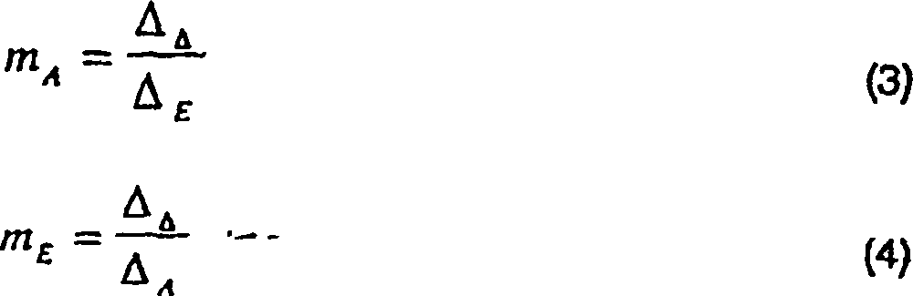
Die
Monopuls-Verhältnisse,
welche durch (3) und (4) berechnet wurden, werden gleich denjenigen sein,
die durch (1) und (2) berechnet wurden, vorausgesetzt, dass die
An tennengruppe planar-rechteckig oder allgemein die Muster die folgenden
allgemeinen Trennbedingungen erfüllen
müssen:
Diese
Bedingung ist auch erforderlich, das Monopuls-Verhältnis bei
adaptiver Hauptkeulen-Aufhebung zu erhalten. Die Monopuls-Verhältnisse,
welche von den beiden Verhältnissen
hergeleitet werden, können
als Übereinstimmungsprüfung zum
Bestimmen eines oder mehrerer Ziele verwendet werden. Für das Vorhandensein
eines Ziels dienen die Monopuls-Verhältnisse, welche die Gleichungen
(1)–(4)
verwenden, als unabhängige
Schätzung,
und werden daher gemittelt, um eine bessere Schätzung zu bekommen. Im Fall
von zwei Zielen innerhalb des Hauptantennenstrahls werden die Azimuth-
und Elevations-Monopuls-Werte, welche von (1) und (3) und (2) und
(4) hergeleitet werden, nicht gleich werden. In Wirklichkeit haben
der Azimuth-Monopuls-Wert (Gleichung (1)) und der Elevations-Monopuls-Wert
(unter Verwendung von Gleichung (2)) und zwei vorhandenen Quellen
die folgenden Gleichungen: 
Hier
sind die Monopuls-Werte (mA1, mE1)
und (mA2, mE2) die
Monopuls-Werte von zwei Zielen. Die Monopuls-Werte, welche die Differenzverarbeitung
verwenden (Gleichung (3) und (4)) werden durch folgendes angegeben: 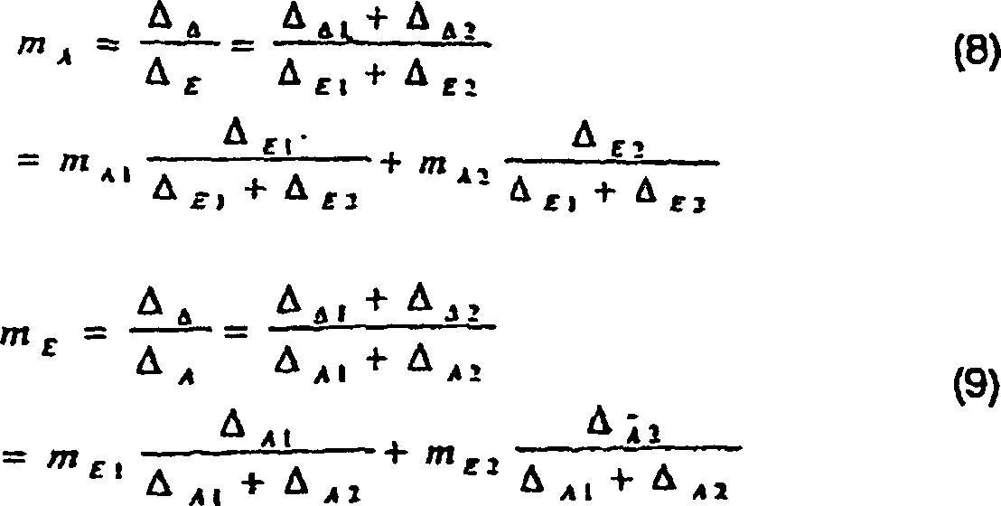
Dies
sind gewichtete Durchschnittswerte der entsprechenden Azimuth- und
Elevations-Monopuls-Werte der beiden Quellen. Die Wichtungen sind
die Summen- bzw. die Differenzmusterwerte. Dieser Monopuls-Wert-Übereinstimmungstest
kann zur Bestimmung für
eine oder zwei Quellen verwendet werden. Wenn sie gleich oder beieinander
sind, gibt es eine Quelle, und die Monopuls-Werte können gemittelt
werden, um eine bessere Schätzung
zu ergeben. Wenn sie unterschiedlich sind, gibt es dann mehr als
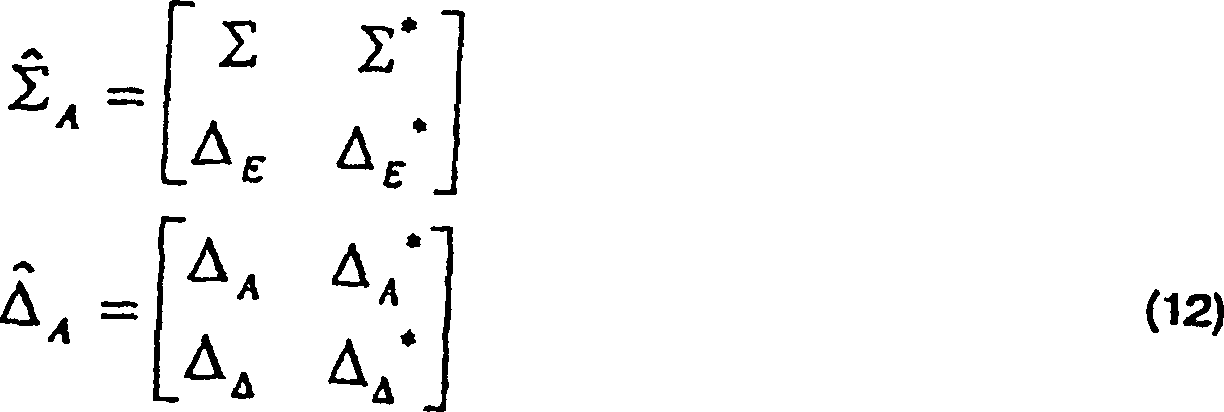
ein Ziel, und man kann die folgenden verallgemeinerten Matrix-Monopuls-Verhältnisse
verwenden: 
Ähnlich wird
für die
Elevations-Winkel-Schätzung
das folgende Matrix-Monopuls-Verhältnis hergeleitet: 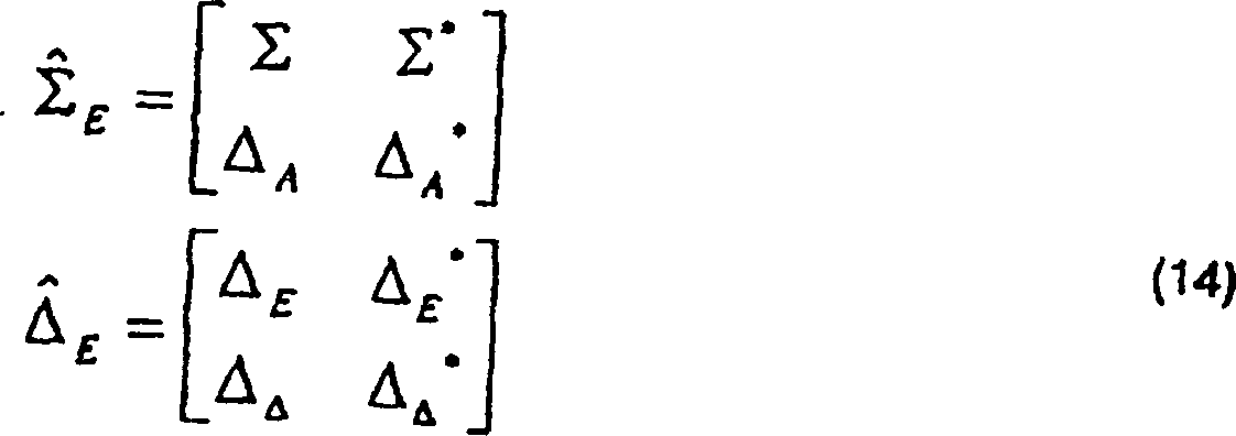
Die
Elevations-Monopuls-Verhältnis-Matrix
hat die folgende Eigenwert-Dekomposition, von der die Elevations-Winkel
von einer Nachschlagetabelle bestimmt werden können: 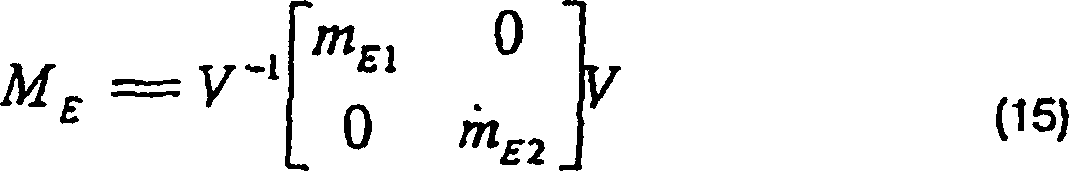
Das Matrix-Monopuls-Verhältnis-Verarbeitungsverfahren kann wie folgt zusammengefasst werden:
- (1) Bilde die Matrix-Monopuls-Verhältnisse (Gleichung (11) und (13));
- (2) Bestimme die Eigenwerte der Monopuls-Verhältnis-Matrix (Gleichung (10) und (15));
- (3) Bestimme die Winkel von der Nachschlagetabelle (
3 ); - (4) Bestimme das Paaren der Azimuth- und Elevationswinkel auf der Basis der Ähnlichkeit der Eigenvektoren (Gleichungen (10) und (15)).
- (1) Form the matrix-monopulse ratios (Equations (11) and (13));
- (2) Determine the eigenvalues of the monopulse ratio matrix (Equations (10) and (15));
- (3) Determine the angles from the look-up table (
3 ); - (4) Determine the pairing of the azimuth and elevation angles based on the similarity of the eigenvectors (equations (10) and (15)).
Dieser
Algorithmus erfordert eine Zwei-Eigenwert-Dekomposition und Azimuth- und Elevations-Winkelpaarung.
Diese Positur kann weiter dadurch verfeinert werden, dass die obige
Azimuthwinkel- und Elevationswinkel-Matrixverarbeitung die folgenden
komplexen Gleichungen verwenden: 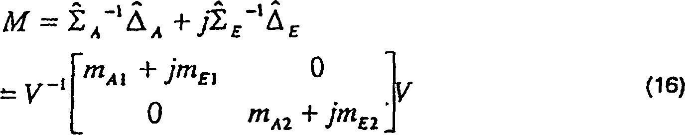
Damit
ist lediglich eine Eigenwert-Dekomposition erforderlich, und die
Azimuth- und Elevationswinkel werden
automatisch gepaart. Der Winkelschätzungsalgorithmus, bei dem
der Monopuls-Verhältnis-Übereinstimmungstest
und die Eigenwert-Dekomposition der Monopuls-Verhältnis-Matrix
verwendet werden, ist in
Wie
in
Es
wird ein Beispiel verwendet, um die Super-Auflösungsfahigkeit dieses Verfahrens
zu zeigen. Die Antenne ist zirkular mit einem Durchmesser von 9
Inches entsprechend der Keulenbreite von 6 Grad. Es werden zwei
Quellen von Azimuth- und Elevations-Winkeln von (0,0) und (3,3)
mit gleichen Signal-Rausch-Verhältnissen
von 30 dB simuliert. Herkömmliche
Monopuls-Verarbeitungsschätzungen
von
Claims (16)
Applications Claiming Priority (2)
| Application Number | Priority Date | Filing Date | Title |
|---|---|---|---|
| US607004 | 2000-06-29 | ||
| US09/607,004 US6404379B1 (en) | 2000-06-29 | 2000-06-29 | Matrix monopulse ratio radar processor for two target azimuth and elevation angle determination |
Publications (2)
| Publication Number | Publication Date |
|---|---|
| DE60109990D1 DE60109990D1 (en) | 2005-05-19 |
| DE60109990T2 true DE60109990T2 (en) | 2006-05-04 |
Family
ID=24430389
Family Applications (1)
| Application Number | Title | Priority Date | Filing Date |
|---|---|---|---|
| DE60109990T Expired - Lifetime DE60109990T2 (en) | 2000-06-29 | 2001-06-28 | Monopulse radar processor for determining the azimuth and elevation angles of two targets over a matrix of amplitude ratios |
Country Status (3)
| Country | Link |
|---|---|
| US (1) | US6404379B1 (en) |
| EP (1) | EP1167995B1 (en) |
| DE (1) | DE60109990T2 (en) |
Families Citing this family (21)
| Publication number | Priority date | Publication date | Assignee | Title |
|---|---|---|---|---|
| US6622118B1 (en) | 2001-03-13 | 2003-09-16 | Alphatech, Inc. | System and method for comparing signals |
| US6720910B2 (en) * | 2001-08-16 | 2004-04-13 | Lockheed Martin Corporation | Pri-staggered post-doppler adaptive monopulse processing for detection and location of a moving target in ground clutter |
| US6567034B1 (en) * | 2001-09-05 | 2003-05-20 | Lockheed Martin Corporation | Digital beamforming radar system and method with super-resolution multiple jammer location |
| US6498581B1 (en) * | 2001-09-05 | 2002-12-24 | Lockheed Martin Corporation | Radar system and method including superresolution raid counting |
| US7136012B2 (en) * | 2003-04-01 | 2006-11-14 | Lockheed Martin Corporation | Approach radar with array antenna having rows and columns skewed relative to the horizontal |
| US6801156B1 (en) * | 2003-07-25 | 2004-10-05 | Lockheed Martin Corporation | Frequency-agile monopulse technique for resolving closely spaced targets |
| US7205932B2 (en) * | 2004-01-29 | 2007-04-17 | Bae Systems Information And Electronic Systems Integration Inc. | Method and apparatus for improved determination of range and angle of arrival utilizing a two tone CW radar |
| US7250902B2 (en) * | 2005-07-19 | 2007-07-31 | Raytheon Company | Method of generating accurate estimates of azimuth and elevation angles of a target for a phased—phased array rotating radar |
| JP4351266B2 (en) * | 2007-05-10 | 2009-10-28 | 三菱電機株式会社 | Frequency modulation radar equipment |
| US7535408B2 (en) * | 2007-08-31 | 2009-05-19 | Lockheed Martin Corporation | Apparatus and methods for detection of multiple targets within radar resolution cell |
| US7671789B1 (en) | 2008-10-03 | 2010-03-02 | Lockheed Martin Corporation | Method and system for target detection and angle estimation based on a radar signal |
| US7859451B2 (en) * | 2008-11-18 | 2010-12-28 | Lockheed Martin Corporation | Method and system for monopulse radar target angle determination |
| US8269665B1 (en) * | 2010-01-29 | 2012-09-18 | Lockheed Martin Corporation | Monopulse angle determination |
| CH704552A8 (en) * | 2011-02-17 | 2012-10-15 | Huber+Suhner Ag | Array antenna. |
| US8577298B2 (en) * | 2011-06-20 | 2013-11-05 | Lockheed Martin Corporation | Multi-element magnetic receiver for interference suppression and signal enhancement |
| RU2622399C1 (en) * | 2016-07-06 | 2017-06-15 | Федеральное государственное автономное образовательное учреждение высшего образования "Санкт-Петербургский государственный университет аэрокосмического приборостроения" (ГУАП) | Quasi-mono-pulse secondary radar |
| US10705202B2 (en) * | 2017-01-19 | 2020-07-07 | GM Global Technology Operations LLC | Iterative approach to achieve angular ambiguity resolution |
| US20210025969A1 (en) * | 2018-03-06 | 2021-01-28 | Hitachi Automotive Systems, Ltd. | Radar device |
| KR102122829B1 (en) | 2018-04-10 | 2020-06-15 | 고려대학교 산학협력단 | Target Location Estimation Method for Distributed MIMO Radar using Extended BRM Scheme |
| CN110068833B (en) * | 2019-05-05 | 2021-10-29 | 中国科学院电子学研究所 | Synthetic aperture laser radar imaging method, instrument and system |
| CN113609450B (en) * | 2021-02-22 | 2023-11-03 | 天津大学 | Large-scale sparse array DoA estimation method based on LCGAMP network and 1-Bit quantization |
Family Cites Families (12)
| Publication number | Priority date | Publication date | Assignee | Title |
|---|---|---|---|---|
| US3471857A (en) * | 1967-05-24 | 1969-10-07 | Singer General Precision | Planar array antenna arrangements |
| US4005421A (en) * | 1973-05-30 | 1977-01-25 | Westinghouse Electric Corporation | Monopulse radar system and method for improved low elevation tracking |
| US3935572A (en) * | 1973-11-23 | 1976-01-27 | Hughes Aircraft Company | System for resolving velocity ambiguity in pulse-doppler radar |
| FR2527785A1 (en) * | 1982-05-27 | 1983-12-02 | Thomson Csf | METHOD AND DEVICE FOR REDUCING THE POWER OF THE INTERFERENCE SIGNALS RECEIVED BY THE LATERAL LOBES OF A RADAR ANTENNA |
| US6195035B1 (en) * | 1984-10-12 | 2001-02-27 | Textron Systems Corporation | Cylindrical monopulse |
| DE3630482A1 (en) * | 1986-09-08 | 1988-05-11 | Uhland Goebel | Circulator having a reversible transmission direction |
| US5059968A (en) * | 1990-12-11 | 1991-10-22 | Raytheon Company | Radar system and method of operating such system |
| US5302961A (en) * | 1992-12-28 | 1994-04-12 | General Electric Co. | Antenna aperture with mainlobe jammer nulling capability |
| US5371506A (en) * | 1993-07-19 | 1994-12-06 | General Electric Co. | Simultaneous multibeam approach for cancelling multiple mainlobe jammers while preserving monopulse angle estimation accuracy on mainlobe targets |
| WO1997022890A1 (en) * | 1995-12-19 | 1997-06-26 | Siemens Schweiz Ag | Process and amplitude or phase-single pulse radar device for locating flying objects |
| US6087974A (en) * | 1998-08-03 | 2000-07-11 | Lockheed Martin Corporation | Monopulse system for target location |
| IL126284A (en) * | 1998-09-17 | 2002-12-01 | Netmor Ltd | System and method for three dimensional positioning and tracking |
-
2000
- 2000-06-29 US US09/607,004 patent/US6404379B1/en not_active Expired - Fee Related
-
2001
- 2001-06-28 EP EP01115823A patent/EP1167995B1/en not_active Expired - Lifetime
- 2001-06-28 DE DE60109990T patent/DE60109990T2/en not_active Expired - Lifetime
Also Published As
| Publication number | Publication date |
|---|---|
| EP1167995B1 (en) | 2005-04-13 |
| DE60109990D1 (en) | 2005-05-19 |
| EP1167995A2 (en) | 2002-01-02 |
| EP1167995A3 (en) | 2002-09-11 |
| US6404379B1 (en) | 2002-06-11 |
Similar Documents
| Publication | Publication Date | Title |
|---|---|---|
| DE60109990T2 (en) | Monopulse radar processor for determining the azimuth and elevation angles of two targets over a matrix of amplitude ratios | |
| DE60218244T2 (en) | Digital adaptive subarray beamforming and deterministic sum and difference beamforming with noise cancellation and monopole ratio maintenance | |
| DE60302379T2 (en) | Radar processing system and method for detecting and monitoring targets | |
| US6087974A (en) | Monopulse system for target location | |
| DE102008059424B4 (en) | Secondary radar system with dynamic sectorization of the space to be monitored using multi-antenna arrangements and methods for this | |
| US6531976B1 (en) | Adaptive digital beamforming radar technique for creating high resolution range profile for target in motion in the presence of jamming | |
| Brown et al. | STAP for clutter suppression with sum and difference beams | |
| US6720910B2 (en) | Pri-staggered post-doppler adaptive monopulse processing for detection and location of a moving target in ground clutter | |
| US20030142011A1 (en) | Surface wave radar | |
| Farina et al. | Electronic counter-countermeasures | |
| CA2082692A1 (en) | Adaptive digital beamforming architecture and algorithm for nulling mainlobe and multiple sidelobe radar jammers while preserving monopulse ratio angle estimation accuracy | |
| US9075128B2 (en) | Grating lobe mitigation in presence of simultaneous receive beams | |
| Skolnik et al. | Senrad: An advanced wideband air-surveillance radar | |
| US5907302A (en) | Adaptive elevational scan processor statement of government interest | |
| CN109765529B (en) | Millimeter wave radar anti-interference method and system based on digital beam forming | |
| DE112017006884T5 (en) | RADAR DEVICE | |
| DE60027418T2 (en) | PROCESS FOR DISPLAYING EXCEPT AXIAL SIGNALS FOR MONOPULAR RADAR | |
| Kuschel | VHF/UHF radar. Part 2: Operational aspects and applications | |
| DE60109363T2 (en) | Monopulse radar processor for the resolution of two signal sources | |
| Hiemstra | Robust implementations of the multistage Wiener filter | |
| EP0291919B1 (en) | Airborne radar device | |
| Rabideau et al. | A signal processing architecture for space-based GMTI radar | |
| Narasimhan et al. | Mitigation of sidelobe clutter discrete using sidelobe blanking technique in airborne radars | |
| CN114265058A (en) | MIMO radar target angle measurement method and device, electronic equipment and storage medium | |
| Ong et al. | Doppler compensation for JDL for airborne bistatic radar |
Legal Events
| Date | Code | Title | Description |
|---|---|---|---|
| 8364 | No opposition during term of opposition |