
The Study of the Dynamic Behavior for a Tamping Rammer

Department of Mechanical Systems Engineering, Faculty of Industrial Engineering, Robotics and Production Management, Technical University of Cluj-Napoca, 400641 Cluj-Napoca, Romania
Symmetry 2022, 14(5), 980; https://doi.org/10.3390/sym14050980
Submission received: 31 March 2022
/
Revised: 29 April 2022
/
Accepted: 9 May 2022
/
Published: 11 May 2022
(This article belongs to the Special Issue Symmetry in Theoretical and Applied Mechanics)
Abstract
:The paper presents a mechanical and a mathematical model, developed by the author for the study of the dynamical behavior of a tamping rammer. At first, some aspects related to the compaction of soil for construction works are presented. In this study, the soil was modeled using the Kelvin–Voigt model. To validate the mathematical model, a program written in C language, that allows to analyze the parameters that influence the operation of the tamping rammer, was developed. Three constructive variants of tamping rammers, following the variation of the displacements of the frame and the sole and the variation of the impact force were analyzed. In the final part, the variation of the studied parameters is illustrated by means of graphical representations. The variation of the studied parameters becomes symmetrical, related to an equilibrium position. Using the application, developed by the author, the variation of the sole and frame displacements, and the variation of the impact force can be traced. The numerical results obtained by running the application, (using three sets of input data), demonstrate the accuracy and the correctness of the proposed mathematical model by analogy with the values provided by the manufacturers. Finally, further research in this field is presented.
1. Introduction
The soil and the materials that form the basis of some constructions (buildings, roads, railways) are found in their natural state in a loose form, and are defined mainly by three factors: humidity, porosity, and relative density [1].
In most of the cases, the soil is weak in its natural state and is characterized by low mechanical strength. So, in order to ensure a high stability that allows it to withstand heavy loads, the soil must be compacted.
The materials used for the foundations (soil, concrete, etc.) may contain, in addition to the solid fraction, liquid and gaseous fractions. Under the action of external loads, the materials tend to settle after a minimum volume, the liquid part moving towards the surface, as the small solid particles tend to occupy the gaps between the larger particles. The increase of the degree of tamping, respectively of the apparent specific weight in the natural state, determines an increase of the construction stability and of the loads supported by the terrain.
Any study on the behavior of machinery used to increase the mechanical strength of soil must also consider the interaction between the machine and the soil. In addition, the behavior of the soil following the action of the machine must be considered (i.e., the way in which the soil changes its properties) [2].
The behavior of the soils, under the action of the external loads, is characterized by strength and deformability indices that depend on the nature of the terrain, the intensity, the type of loads and acting time, but also on the size and shape of the surface through which the loads are transmitted to the ground.
Under the action of external loads, stresses can occur, and the resulting deformations can be in the form of vertical displacements, horizontal displacements and rotations [3].
From the point of view of the mechanization of construction works, a special interest is presented by the mechanical properties of compressibility, shear strength and linear deformation module. Compressibility is the property of the soil to deform under the action of external compression stresses, i.e., to reduce its volume by reducing the volume of the pores. The main compressibility characteristics of soils are [4]: specific settlement, compressibility coefficient, and lateral pressure coefficient.
In the study of the tamping rammers, the nature of the soil must be considered. Thus, in addition to the detailed knowledge of the operation modes of these machines, it is also necessary to know in detail the effects these machines have on soil during the compaction process.
For the correct study of the phenomena and the establishment of the mathematical relations, it is necessary to represent the soil through a mechanical model. It must reproduce the fundamental properties of the soil in such a way as to obtain the most realistic behavior of the machine–soil assembly. The properties to be modeled using the mechanical model are the following: elasticity, plasticity, viscosity and shear strength.
The mechanical models of the soil that consider only one of these properties, neglecting the others, are simple mechanical models. The most used mechanical models, according to scientific literature [5,6] are: the Hooke model, the Newton model, the Saint-Venant model and the simple Bathelt model.
The paper uses the Kelvin–Voigt mechanical model, widely used to describe the viscoelastic behavior of the soil, the characteristics of the model being presented according to [7,8,9,10,11,12]. The Kelvin–Voigt mechanical model consists of a coil spring and a shock absorber, mounted in parallel. As the soil is not perfectly elastic or perfectly plastic, the Kelvin–Voigt model was considered suitable for this study. Further developments can be made using other mechanical models.
More complex models of the soil were considered in different studies [12,13]. The behavior of the soil under the action of external loads is intensively studied by researchers, and various models of analysis were developed [14,15,16,17].
Landscaping companies use their own mechanical and mathematical models, supplemented by many functional tests and appropriate adjustments.
Mechanical models of tamping rammers have been developed by other authors [5,9]. The model developed by Bărdescu [5] studies the behavior of the compactor in three phases: the jump phase, the soil deformation phase, and the rest phase. The soil deformation phase is also divided into three stages, so that the study of the behavior of the compactor may be performed in five stages, and for each phase different equations of motion can be written.
Broman and Jönsson [9] propose another more compact theoretical model, but the hypotheses used do not consider the loss of contact between the sole and the ground. Additionally, in this variant, three geometric parameters are used to define the movement.
The model proposed in this paper considers the detachment of the sole from the ground, as well as the mounting dimensions of the coil springs. The movement is described using two independent geometric parameters (frame and sole displacements). The analysis of the displacements of the sole and the frame is highlighted through graphs, of great importance being the amplitudes of these displacements, as well as their shape. Unlike the analyzed models, it allows the determination of the impact force on the soil, its graph shows the detachment of the sole from the soil.
By modifying the input data (the dimensions and masses of the components, the characteristics of the coil springs, the damping constant of the cylinder, the working speed, the engine torque, etc.), one can analyze the influence they have on the operation of the machine. Thus, with the help of this theoretical model, both the dynamic behavior of the tamper rammer and the influence of some constructive parameters on its operation are studied, because the geometric dimensions of the components are also considered.
The proposed mathematical model allows a more accurate determination of the dynamic behavior of the tamper rammers and can be developed for the study of vibrations transmitted to the human operator.
The mathematical model was solved by means of a C language application developed by the author, that allows the analysis of the machine’s behavior according to its constructive and kinematic parameters.
2. Mechanical and Mathematical Model of Tamping Rammer
Construction equipment companies offer only the final products, not their mathematical models. At present, in our country, the aim is to develop local products that are competitive with the imported ones. The research activity contributes to the fulfillment of this goal, by developing some models of machines based on which these machines can be designed and manufactured.
The tamping rammers are machines used for compacting the soil by tapping and are used especially in narrow spaces, where the use of other machines is not possible. It is used for compacting the soil around foundations, preparing the soil for pouring concrete, compacting the soil used to fill ditches for pipes or cables, as well as for compacting asphalt in road or pavement repair works. Rammers provide a high impact force (with a high amplitude of the sole displacement) being very suitable for compacting cohesive or semi-cohesive soils. Tamping rammers use three types of compactions: impact, vibration, and kneading. These provide a small compaction depth, between 0.6–0.8 m; the compacted surfaces have small dimensions, but a hard permeable surface crust is obtained, so a high degree of compaction. Due to the inclination of the cylinder axis of the compactor at an angle of 10–17° to the vertical, the rammer can perform a forward movement, by displacing 10–15 cm at each jump. The lifting height of the mallet is 30–100 mm, and the number of strokes/minutes is between 400–800. The mass of the tamping rammers is between 50 and 200 kg.
The compaction effect is obtained by:
- the effect produced on the sole by the connecting rod-crank mechanism;
- the shock produced by the fall of the rammer after performing the jump;
- the effect of low frequency vibrations that are transmitted to the ground each time the rammer falls.
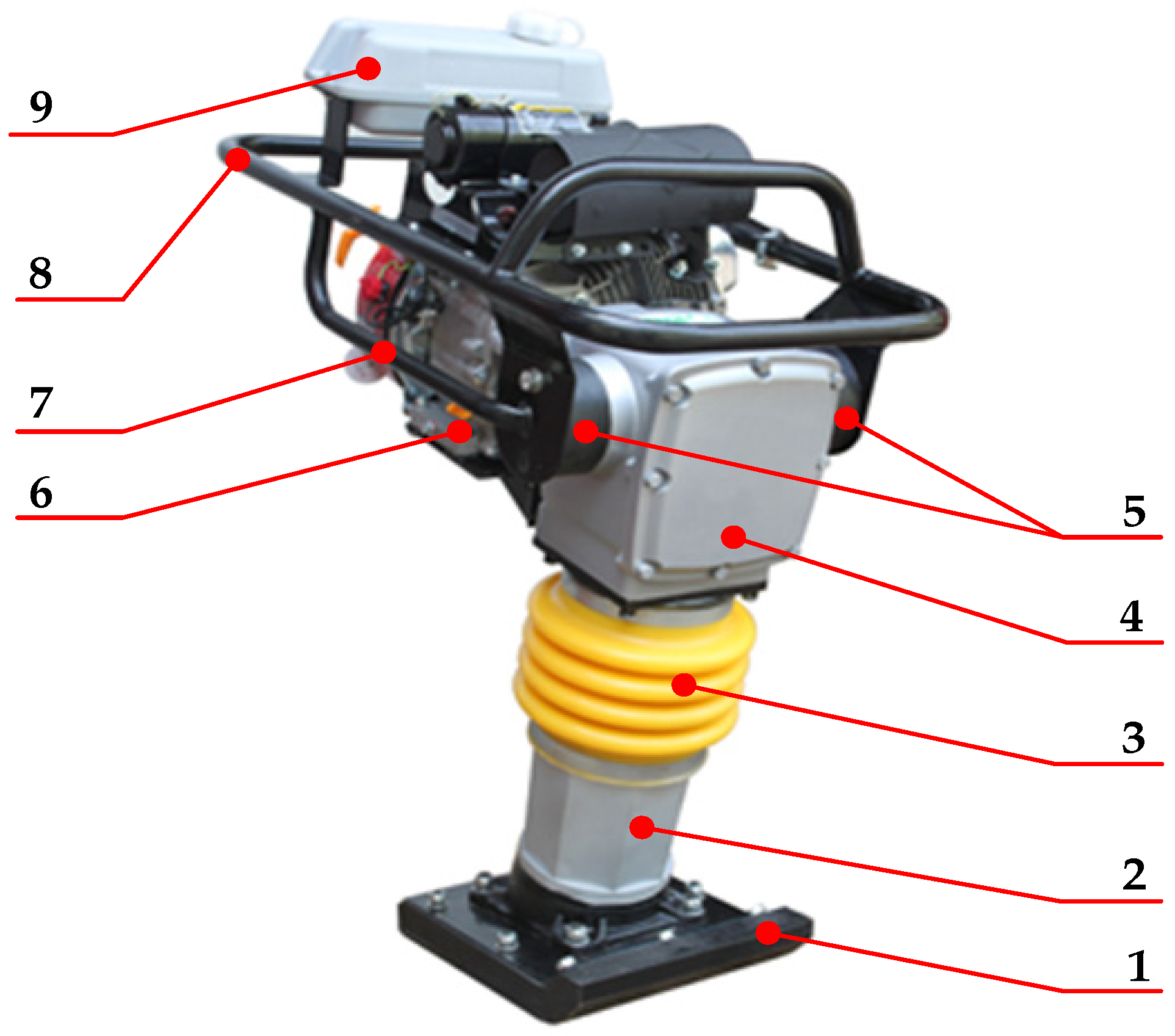
According to Figure 1, the tamping rammer consists of: compacting plate (1), oil cylinder (2), bellows (3), gear reducer (4), anti-vibration rubber elements (5), driving engine (6), frame (7), drive handle (8), and fuel tank (9).
The drive engine can be diesel or gasoline powered, in two or four strokes, with the driving powers with values in the range of 1.4–4 kW, and speeds of 2300–4500 rpm. The mechanical motion from the drive (6) is transmitted to the gear reducer (4) by means of a centrifugal coupling which is not visible in Figure 1. The gear reducer allows the reduction of the speeds up to values comprised between 400–800 rpm. The gear reducer drives a connecting rod-crank mechanism to which a piston connected by means of helical springs acts on the sole (1). The sole performs an oscillating motion with a certain frequency and amplitude. The damping effect is ensured by the bellows cylinder (2, 3), filled with oil; the lack of oil causing a malfunction of the tamping rammer.
The operating of the machine during its functioning is ensured by means of the drive handle (8). To reduce the vibration of the actuating handle, anti-vibration rubber elements (5) are provided between the handle and the frame (7).
During the operation of the machine, the sole performs jumps (detachments from the ground) of heights between 30–100 mm. The frame moves in the vertical direction in the range of 30–50 mm, the vibrations transmitted to the actuating handle (therefore also to the operator) being lower due to the anti-vibration rubber elements.
The dimensions of the compacting plate are in the range (150–300) × (270–350) mm. The rammers have a working speed between 8–20 m/min and a productivity between 175–350 m2/h. The value of the impact force is given by the mass of the machine, along with the force developed by the helical springs in the cylinder, this value being between 9–21 kN.
Considering the aspects presented above, it can be noticed that there are a number of parameters that influence the dynamic behavior of the tamping rammers. The mechanical model of the rammer is simple, without many constructive variants.
The operation of the rammer is influenced by some parameters: kinematic parameters (determined by the characteristics of the drive), geometric parameters (determined by the dimensions of the elements of the machine), mechanical parameters (determined by the mass of the machine or the forces developed in the springs).
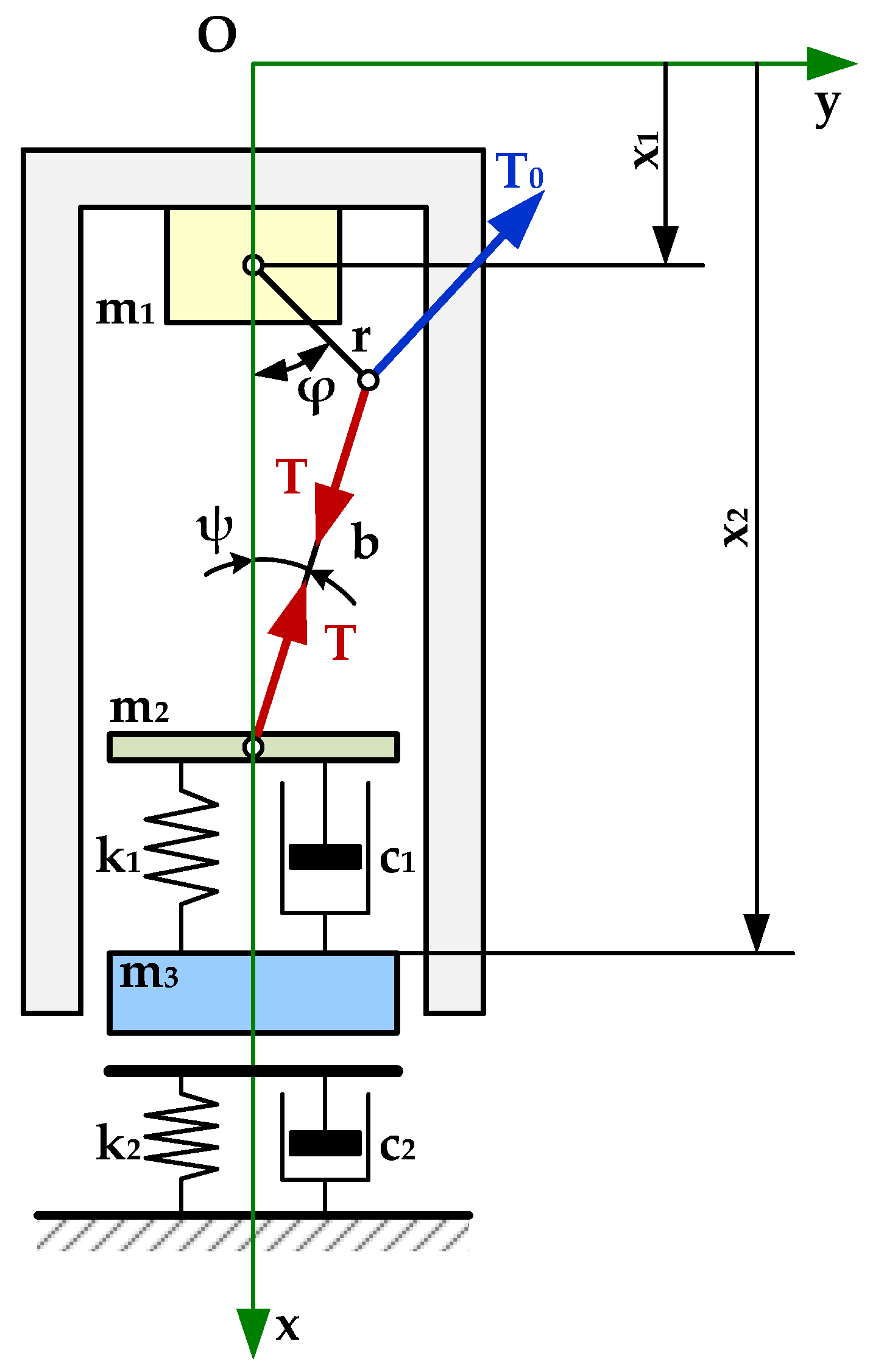
To study the dynamic behavior of a rammer and to determine its operating parameters, the author developed a mechanical model of the compactor (see Figure 2).
In developing the mechanical model, the soil is modeled based on the Kelvin–Voigt model, which consists of a helical spring and a shock absorber mounted in parallel. The values for the elastic and damping constants are selected by considering the category to which the soil belongs, as well as based on its compaction degree.
The elastic constant k2, and the damping constant c2 corresponding to the mathematical model of the soil can be determined based on [7,8]:
where: G—shear modulus, r—the equivalent radius of the rammer plate, ν—Poisson’s coefficient, and γt—the specific gravity of the soil.
In addition, between the elastic constant k and the damping constant c, there is the relation [9,10,11]:
where D is a damping coefficient (whose value, in this paper was considered D = 0.4).
Between G—the shear modulus and E—Young’s elasticity modulus, the following relation can be established:
Considering the mechanical model presented above, the author developed a mathematical model for the study of the dynamic behavior of the rammer [18].
To develop the mathematical model, the following simplifying hypotheses were used:
- the system consists of three masses (the mass of the frame, drive engine and gear reducer, the mass of the connecting rod-crank mechanism together with the spring assembly, the mass of the sole together with the cylinder);
- the displacement is only in the vertical direction (the Ox axis is considered the axis of symmetry);
- all parts, except for the springs, are rigid;
- the driving engine and the coupling parts are modeled as a rotating disc;
- the moment of inertia I and the driving moment M are constant;
- the elastic constants and the damping coefficient are linear.
- In developing the mathematical model, the following notations were applied:
- x1 and x2—the parameters defining the position of the elements which forms the mechanical system (frame and compacting plate);
- M—the torque (constant);
- ω—angular velocity (constant);
- φ—the angle between the crank and the vertical axis (denoted Ox);
- ψ—the angle made by connecting rod with the vertical axis;
- m1—the total mass of the frame, engine, and gear reducer;
- m2—the total mass of the piston, connecting rod, and the springs;
- m3—the total mass of the compacting plate and cylinder;
- r—length of crank;
- b—the length of the connecting rod;
- l1—the length of the springs in the mounted state.
The mechanical system shown in Figure 2 is a system with two degrees of freedom, whose elements perform vertical movements, the geometric parameters defining the movement of the system being x1—frame displacement, and x2—compacting plate displacement.
The crank rotates at a constant angular velocity in a trigonometric sense, acting on it with a constant torque M. Torque M is replaced by a torque generated by a T0 force applied to the crank end (Figure 2).
Considering the aspects presented above, the following relations can be determined:
Applying Newton’s law leads to the following differential equations that define the motion of m1, m2 and m3 masses:
In the Equation (7), it was considered that the mass m3 is not in permanent contact with soil.
The following differential expression can be obtained:
Thus, Equation (6) becomes:
The unknown represented by T from (5) is replaced in the Equation (9), leading to:
The system of differential equations which describe the motion of the compacting plate and of the frame, respectively, consists of two differential equations:
To solve the system of differential equations, a program written in the C language [19], developed by the author and based on the fourth order Runge–Kutta method [20], was used. This program allows the determination of the movements of the frame and the compacting plate, as well as the variation of the impact force exerted by the machine on the soil surface.
In addition, by using this application, the influences of some parameters on the dynamic behavior of the tamping rammer are also studied.
The input data are:
- m1—the mass of the frame, driving engine and gear reducer altogether [kg];
- m2—the mass of the piston, connecting rod and the springs altogether [kg];
- m3—the mass of the compacting plate and cylinder altogether [kg];
- k1—the elasticity constant of the helical springs [N/m];
- c1—the damping coefficient of the viscous damper [Ns/m];
- r—the length of the crank [m];
- b—the length of the connecting rod [m];
- k2—the elasticity constant of the soil (Kelvin–Voigt model) [N/m];
- c2—the damping coefficient considered at the soil modeling (Kelvin–Voigt model) [Ns/m];
- M—the moment applied to the crank [Nm];
- n—the rotation speed of the crank [rot/min].
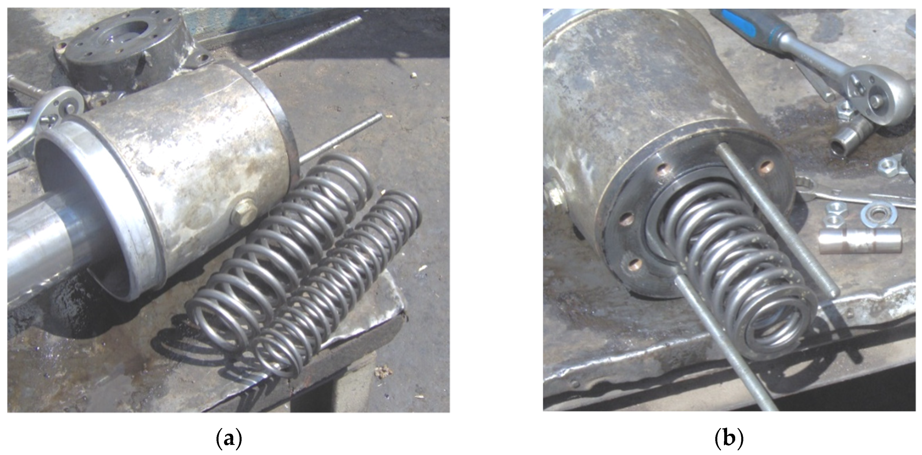
The input data used in the analysis were obtained by studying the catalogues of the tamping rammer’s manufacturers and by measuring/weighing the parts or subassemblies the compactor consists of.
Figure 3 shows some parts of a disassembled compactor for weighing/measuring its components.
Using this program, the dynamic behavior of the tamping rammer can be studied, even before it is designed. It is also possible to analyze an existing variant and to make an improved version of it by redesigning parts.
3. Numerical Modeling
The purpose of this section is to present the results of the numerical modeling of the dynamic behavior applied in case of three different variants of tamping rammers.
The models (mechanical and mathematical) proposed by the author were validated by comparing the results with the ones provided by the manufacturers. It was also intended to validate the proposed models by performing measurements in the process of compacting the soil when using tamping rammers. Further, three different variants of tamping rammers are analyzed. The main characteristics are presented in Table 1.
In the analysis, the aim was to determine the dynamic behavior of the compactor according to its parameters (masses, distances, elastic constants of the springs, damping constants, etc.). Thus, the movements of the frame and the compacting plate, as well as the variation and value of the impact force developed by the tamping rammer, were analyzed.
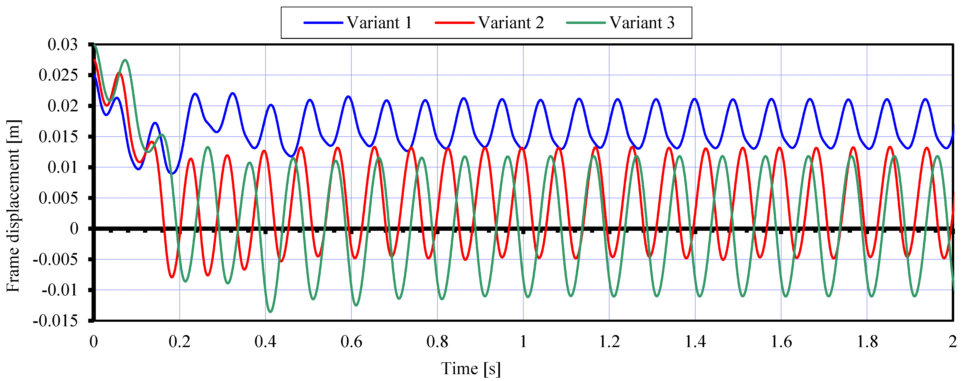
Figure 4 shows the variation of the rammer’s frame for all three analyzed variants:
Analyzing the graph illustrated in Figure 4, it can be noticed that the variations in the frame movements stabilize after a very short period, and these are symmetrical relative to an equilibrium position. In addition, the frame displacements fall into small value ranges, as follows:
- for the first variant, the displacement of the frame is less than 20 mm, so the vibrations transmitted to the human operator are smaller.
- in case of the second variant, the displacement of the frame is approximately 20 mm.
- the third variant has higher values of the frame displacement, of almost 25 mm.
The values obtained for the displacement of the frame are important because the displacement of the frame negatively influences the operation and wear of the engine and the parts of the tamping rammer.
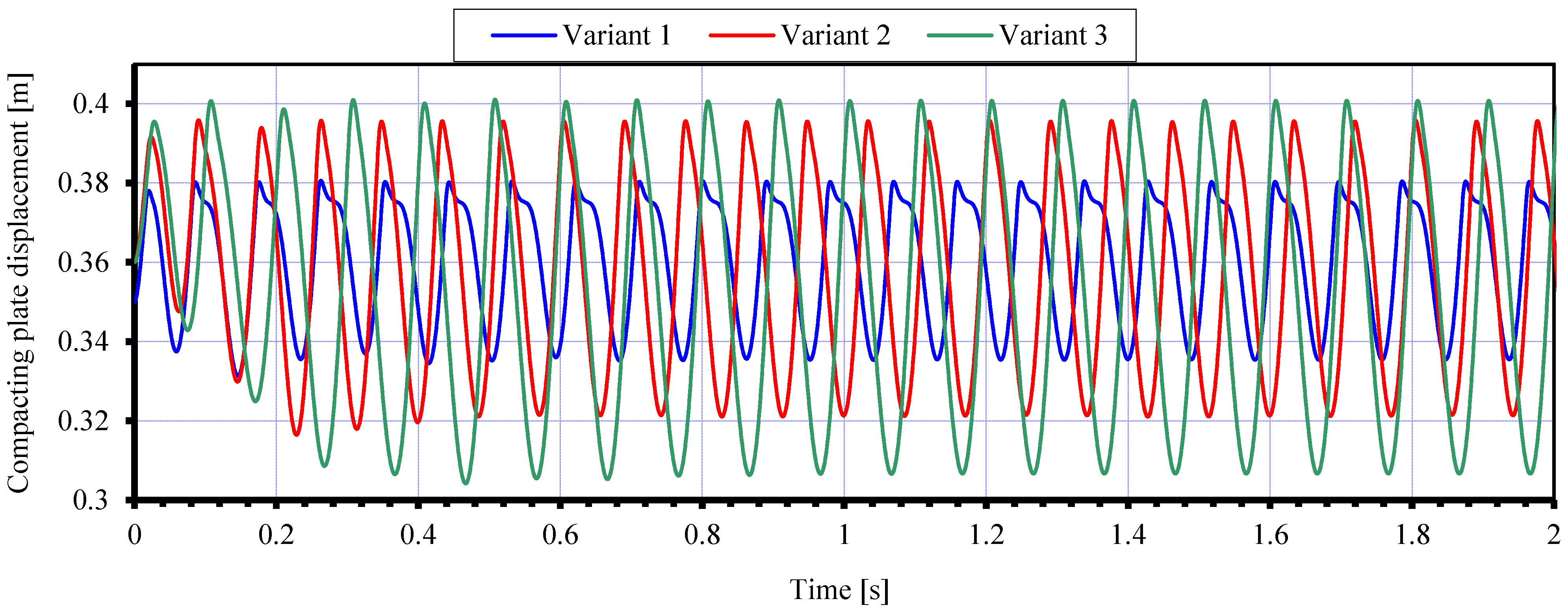
To reduce the vibration transmitted to the human operator, anti-vibration rubber elements are inserted between the frame and the handle. Thus, small variations in the frame displacement cause less vibration to the human operator. In Figure 5, the compacting plate displacements in case of the three analyzed variants are presented. It can be noticed that for each variant, the sole displacement falls within a range of values of 30–100 mm, which is in accordance with the specifications given by the manufacturers.
In the case of the first variant, the displacement of the sole is approximately 45 mm, and in the case of the second variant, the displacement is approximately 80 mm. For the third variant, the displacement of the sole is about 100 mm. The second and the third variations are symmetrical relative to an equilibrium position.
The values of the sole displacements are correlated with some of the input data, such as: engine torque, speed at the output of the reducer, elastic constant of helical springs, and damping constant. It was observed that an increase in the motor moment creates an increase in the displacement of the sole and of the frame as well, with a negative influence on the components of the machine and the human operator. Therefore, an appropriate correlation must be found between the input data (engine torque, speed, spring and damping constants, component masses) and frame and sole displacements.
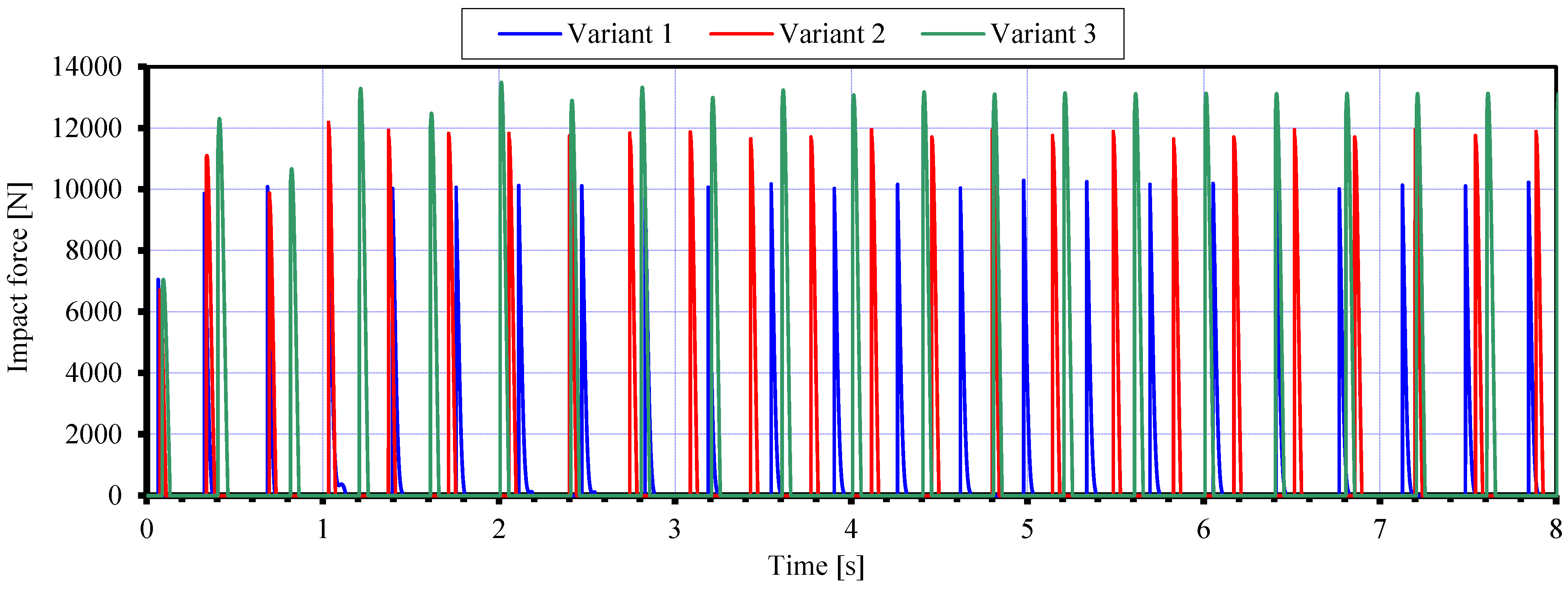
Figure 6 illustrates the variation of the impact force developed by the tamping rammer, for each of the three analyzed variants.
Table 2 shows three variants of tamping rammers produced by several manufacturers. It is noted that the values obtained from running the program for the impact force and the height of the jumps are similar to those given by the manufacturers in the presentation catalogs.
Additionally, from the graphical representation, it can be seen that the time intervals in which the impact force is zero correspond to the moments when the compacting plate of the tamping rammer is not in contact with the soil, i.e., when the compactor performs jumps. The behavior of the tamping rammer is influenced by several parameters. The analysis of the behavior of a tamping rammer variant from its design stage is extremely important. With such an analysis, an optimal version of a compactor can be developed, so that both the operating and ergonomic requirements are met.
Another extremely important issue is that of the vibrations transmitted to the human operator. Anti-vibration elements are inserted between the handle and the frame to reduce the vibrations transmitted to the human operator. That is why it is very important to know how the machine frame moves. The movement of the compacting plate illustrates the behavior of the machine and is relevant in the soil compaction process. For this reason, it is important to know the movement limits of the plate. The impact force developed by the compactor is the most important factor in the soil compaction process, so it is necessary to know its variation. The symmetrical/asymmetrical behavior is specific to the dynamic technological response of these machines.
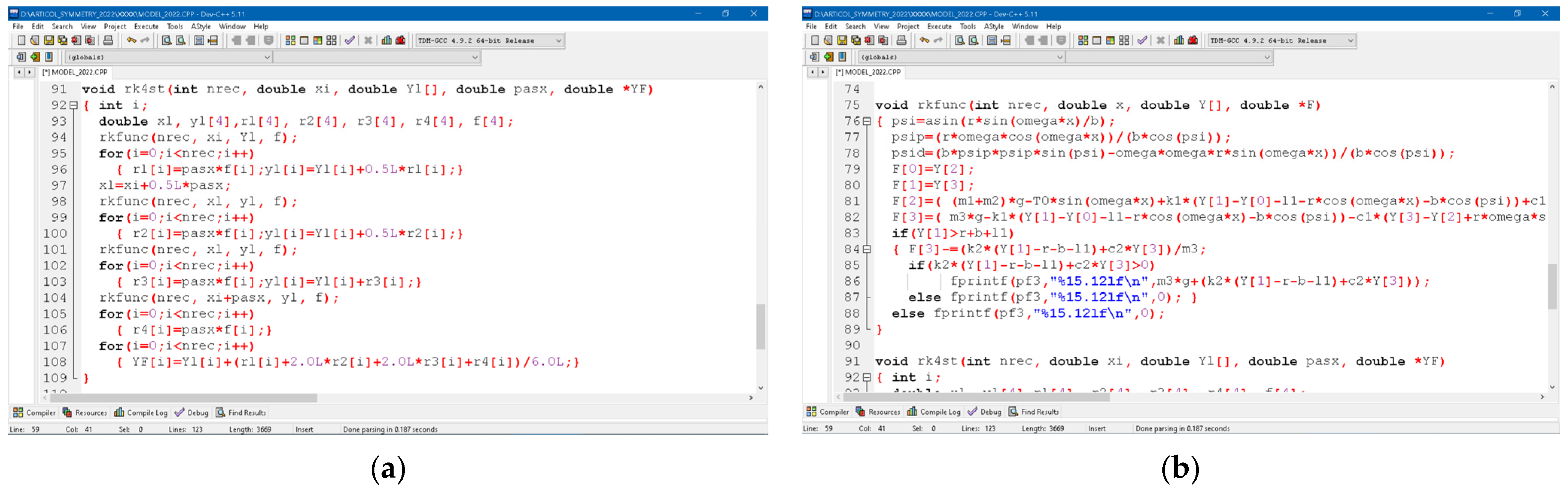
Based on the mathematical model, the author developed a software application in the C language to analyze the dynamic behavior of a tamping rammer.
This program implements the fourth order Runge–Kutta method to solve the system of differential equations. Figure 7a shows the function used for implementing the Runge–Kutta method, and Figure 7b shows the function created to solve the system of differential equations.
The program reads the input data and calls the two functions; the results are displayed on the screen and are written to the files.
The graphical representations were plotted based on the values obtained after running the program, using a series of input data (as shown in Table 1).
The software allows the way in which certain parameters influence the dynamic behavior of the machine to be analyzed. The influence of the constructive parameters on the impact force developed by the machine can also be analyzed.
The mathematical model, along with the software, provides an extremely useful tool for analyzing the dynamic behavior of tamping rammers.
4. Discussion
The study presented in the previous chapter shows the behavior of a tamping rammer during its operation.
The mathematical model, previously presented, can be applied for the dynamic analysis of any variant of tamping rammer. By changing the values of some input parameters (kinematic, constructive), an improved version of the compactor may be obtained. The impact force on the soil developed by the compactor can be analyzed by using the program developed by the author.
In addition, the mechanical model previously presented can be improved and customized for the analysis of the vibrations of the handle, knowing the implications that the vibrations of the handle have on the health of the human operator.
Soil modeling was performed using the Kelvin–Voigt model; further analysis can be performed using other soil models.
5. Conclusions
It is topical to carry out projects, especially in the construction industry, to allow the development of appropriate work equipment. Thus, it was considered appropriate to develop a mathematical model for a tamper rammer. Using this mathematical model, it is possible to study the dynamic behavior of a tamping rammer, as well as the influence on it of various parameters (kinematic or constructive).
There are few theoretical models of tamper rammers treated in the scientific literature, and the manufacturing companies do not provide useful information in this area. The model proposed by the author considers both the dimensions and masses of the component elements, as well as the characteristics of the elastic and damping elements.
The soil is modeled using the Kelvin–Voigt model, thus highlighting its viscoelastic properties. In this first development, it was considered that this model is sufficiently accurate. Further developments may be based on more complex soil models.
Developing the theoretical model and the program can be the first step in designing of a tamping rammer. In addition, based on the program, an analysis of the behavior of the machine according to the input data can be performed.
However, it should be mentioned that there is a large variety of constructive variants, the author taking into analysis over 50 variants of tamping rammers.
Depending on the manufacturer, the characteristics of these machines are different, so the proposed model can be considered a very useful tool in analyzing the dynamical behavior and performance of tamping rammers. For example, a machine weighing 60 kg can provide an impact force in the range of 10–14 kN, depending on the design.
Because the dynamic behavior of the compactor depends on several factors, it is very difficult to configure an “optimal” variant. The changing of some input data can improve the values of a parameter (i.e., impact force), but it can increase the displacement of the frame or sole, with negative impact on the operation of the machine components.
The author proposes a more realistic mathematical model for analyzing the behavior of a tamping rammer, along with a software, written in C language.
To validate the mathematical model and the program, three sets of input data were used, which correspond to three different variants of compactors. The values obtained for the sole movement and the impact force are similar to those given by the manufacturers.
A more complex study can be carried out to develop a variant of tamping rammer that ensures the development of a high impact force, with the lowest energy consumption.
Using other mechanical soil models, it is possible to analyze the behavior of the machine in the case of different types of soils, by determining its efficiency.
Using this model as a starting point, more complex models can be developed. For example, a soil-compacting machine with adjustable characteristics (depending on the elastic and damping elements), or an electrically operated machine that is quieter and more environmentally friendly, can be developed. A mathematical model can also be designed to study the vibrations transmitted to the human operator.
Funding
This research received no external funding.
Institutional Review Board Statement
Not applicable.
Informed Consent Statement
Not applicable.
Data Availability Statement
Not applicable.
Conflicts of Interest
The author declares no conflict of interest.
References
- Ishibashi, I.; Hazarika, H. Soil Mechanics Fundamentals and Applications, 2nd ed.; CRC Press: Boca Raton, FL, USA, 2015; p. 420. [Google Scholar]
- Zhu, H.H.; Liu, L.C.; Pei, H.F.; Shi, B. Settlement analysis of viscoelastic foundation under vertical line load using a fractional Kelvin-Voigt model. Geomech. Eng. 2012, 4, 67–78. [Google Scholar] [CrossRef] [Green Version]
- Păunescu, M.; Pop, V.; Silion, T. Geotehnică şi Fundaţii; Editura Didactică şi Pedagogică: Bucharest, Romania, 1982. [Google Scholar]
- Romanescu, C.; Jercan, S.; Pauca, C.; Racanel, I. Drumuri. Calcul şi Proiectare; Editura Tehnică: Bucharest, Romania, 1980. [Google Scholar]
- Bărdescu, I. Studiul Vibraţiilor la Plăcile Vibratoare Pentru Compactarea Pământurilor. Ph.D. Thesis, Institutul Politehnic Bucureşti, Bucharest, Romania, 1971. [Google Scholar]
- Mihăilescu, Ş.; Vlasiu, G. Maşini de Construcţii şi Procedee de Lucru; Editura Didactică şi Pedagogică: Bucharest, Romania, 1973. [Google Scholar]
- Richart, F.E.; Hall, J.R.; Woods, R.D. Vibrations of Soils and Foundations; Prentice-Hall: Englewood Cliffs, NJ, USA, 1970. [Google Scholar]
- Verruijt, A. Soil Dynamics; Delft University of Technology: Delft, The Netherlands, 2004; Available online: www.vulcanhammer.com (accessed on 30 May 2006).
- Broman, G.; Jönsson, A. The nonlinear behaviour of a rammer soil compaction tamping machine. In Proceeding of the 14th ASCE Engineering Mechanics Conference, Austin, TX, USA, 21–24 May 2000. [Google Scholar]
- Jönsson, A.; Bathelt, J.; Broman, G. Implications of modelling one-dimensional impact by using a spring and damper element. J. Multi-Body Dyn. 2005, 219, 299–305. [Google Scholar] [CrossRef] [Green Version]
- Raymond, G.P. Prepared Notes for Geotechnical Engineering; Faculty of Applied Science; Queen’s University: Kingston, ON, Canada, 2005. [Google Scholar]
- Bratu, P.; Dragan, N.; DOBRESCU, C. Dynamic Performances of Technological Vibrating Machines. Symmetry 2022, 14, 539. [Google Scholar] [CrossRef]
- DOBRESCU, C. Analysis of Dynamic Earth Stiffness depending on Structural Parameters in the Process of Vibration Compaction. Rom. J. Acoust. Vib. 2020, 16, 174–177. [Google Scholar]
- DOBRESCU, C. Dynamic Response of the Newton Voigt–Kelvin Modelled Linear Viscoelastic Systems at Harmonic Actions. Symmetry 2020, 12, 1571. [Google Scholar] [CrossRef]
- Bardet, J.P. A Viscoelastic Model for the Dynamic Behavior of Saturated Poroelastic Soils. J. Appl. Mech. 1992, 59, 128–135. [Google Scholar] [CrossRef]
- Bratosin, D.; Sireteanu, T. Hysteretic Damping Modelling by Nonlinear Kelvin-Voigt Model. Proc. Rom. Acad. 2002, 3, 99–104. [Google Scholar]
- Dobrescu, C.F. The Zener Rheological Viscoelastic Modelling of the Dynamic Compaction of the Ecologically Stabilized Soils. Appl. Math. Mech. Eng. 2019, 62, 281–286. [Google Scholar]
- CRISAN, A.V.; Morariu-Gligor, R.M. A Study on the Impact Force in Case of Tamping Rammers. Rom. J. Acoust. Vib. 2019, 16, 78–83. [Google Scholar]
- Press, W.; Teukolsky, S.; Vetterling, W.; Flannery, B. Numerical Recipes in C—The Art of Scientific Computing, 2nd ed.; Cambridge University Press: Cambridge, UK, 1992. [Google Scholar]
- Cartwright, J.H.E.; Piro, O. The Dynamics of Runge-Kutta Methods. Int. J. Bifurc. Chaos 1992, 2, 427–449. Available online: http://lec.ugr.es/~julyan/publications.html (accessed on 30 May 2006). [CrossRef] [Green Version]
Figure 1.
The main components of a tamping rammer.

Figure 2.
The mechanical model of the tamping rammer.

Figure 3.
Components of the tamping rammer: (a) helical springs unassembled, (b) helical springs mounted.
Figure 3.
Components of the tamping rammer: (a) helical springs unassembled, (b) helical springs mounted.

Figure 4.
The displacements of the frame for all tree analyzed variants.

Figure 5.
The displacements of the compacting plate in the three analyzed variants.

Figure 6.
The variation of the impact force for the three analyzed variants.

Figure 7.
The function that uses the fourth order Runge–Kutta method. (a) The function used to implement the Runge–Kutta method. (b) The function created to solve the system of differential equations.
Figure 7.
The function that uses the fourth order Runge–Kutta method. (a) The function used to implement the Runge–Kutta method. (b) The function created to solve the system of differential equations.


Table 1.
The characteristics of the analyzed tamping rammers.
| Considered Parameter | Symbol | Variant 1 | Variant 2 | Variant 3 |
|---|---|---|---|---|
| The mass of the frame, driving engine and gear reducer altogether [kg] | m1 | 35 | 45 | 57 |
| The mass of the piston, connecting rod and of the spring’s assembly altogether [kg] | m2 | 4 | 6 | 8 |
| The mass of the compacting plate and cylinder assembly altogether [kg] | m3 | 11 | 18 | 25 |
| The length of the crank [m] | r | 0.025 | 0.027 | 0.030 |
| The length of connecting rod [m] | b | 0.210 | 0.225 | 0.230 |
| The length the springs in mounted state [m] | l1 | 0.130 | 0.135 | 0.130 |
| The elastic constant of the helical springs from the tamping rammer [N/m] | k1 | 65,000 | 75,000 | 70,000 |
| The damping coefficient of the viscous damper [Ns/m] | c1 | 330 | 300 | 240 |
| The moment applied to the crank [Nm] | M | 15 | 20 | 25 |
| Crank’s rotation speed [rpm] | n | 670 | 700 | 600 |
Table 2.
Some characteristics for the tamping rammers offered by the manufacturers.
| Considered Parameter | Symbol | MIKASA MT55 | Belle RT 65X | MIKASA MT 72FW |
|---|---|---|---|---|
| The mass of the tamping rammer [kg] | m | 57 | 67 | 85 |
| Impact force [kN] | F | 9,8 | 12 | 13,7 |
| The height of the jumps [mm] | h | 30–70 | 50–80 | 40–85 |
Publisher’s Note: MDPI stays neutral with regard to jurisdictional claims in published maps and institutional affiliations. |
© 2022 by the author. Licensee MDPI, Basel, Switzerland. This article is an open access article distributed under the terms and conditions of the Creative Commons Attribution (CC BY) license (https://creativecommons.org/licenses/by/4.0/).
Share and Cite
MDPI and ACS Style
Morariu-Gligor, R.M. The Study of the Dynamic Behavior for a Tamping Rammer. Symmetry 2022, 14, 980. https://doi.org/10.3390/sym14050980
AMA Style
Morariu-Gligor RM. The Study of the Dynamic Behavior for a Tamping Rammer. Symmetry. 2022; 14(5):980. https://doi.org/10.3390/sym14050980
Chicago/Turabian StyleMorariu-Gligor, Radu Mircea. 2022. "The Study of the Dynamic Behavior for a Tamping Rammer" Symmetry 14, no. 5: 980. https://doi.org/10.3390/sym14050980
Note that from the first issue of 2016, this journal uses article numbers instead of page numbers. See further details here.