
An Investigation of the Influence of Temperature and Technical Condition on the Hydraulic Shock Absorber Characteristics


Faculty of Mechanical Engineering, Military University of Technology, gen. Sylwestra Kaliskiego Street 2, 00-908 Warsaw, Poland
Appl. Sci. 2022, 12(24), 12765; https://doi.org/10.3390/app122412765
Submission received: 14 November 2022
/
Revised: 2 December 2022
/
Accepted: 9 December 2022
/
Published: 12 December 2022
(This article belongs to the Special Issue Automotive Safety and Security Engineering: From Theories to Practices)
Abstract
:The paper presents issues related to the operation of hydraulic shock absorbers. The primary objective was to determine the influence of temperature and the technical condition on the damping properties of a twin-tube hydraulic shock absorber. Three units (one new and two used) of the same type of a shock absorber were used for testing. During the tests, the shock absorber was subjected to sinusoidal excitation at fixed values of frequency and displacement amplitudes. There are few low-temperature tests of shock absorbers available in the literature; thus, great emphasis was placed on this aspect of the study. The characteristics of the shock absorbers were determined from a temperature of −30 °C until a steady-state temperature was reached at a given excitation. The resistance force at this temperature is about 2.5 times higher than at 20 °C. The study shows that such high forces can lead to the failure of shock absorber components (especially the valves). The amount of energy dissipated in a single operating cycle of a shock absorber decreases non-linearly with the increase of the temperature. Understanding the temperature dependence of the shock absorber in combination with the cooling curve allows for the steady-state temperature to be estimated at a given excitation. The study also shows that the installation of used shock absorbers in vehicles is not acceptable. Although there are no external signs of wear, their characteristics can differ significantly from those of new shock absorbers.
1. Introduction
In order to achieve an adequate level of driving comfort and safe-vehicle handling, the vibrations induced in the vehicle structure must be dampened. The basic mechanisms for the dissipation of vibration energy in vehicles include dry friction (which occurs at the interface between interacting components) and viscous resistance forces (in fluids). Dry friction damping is mainly used in vehicles with multi-leaf spring suspension. However, in the course of vehicle operation, the conditions of interaction between the leaf spring plates change; thus, the coefficient of friction [1] changes significantly. It then affects the dynamics of the car body and, for example, changes the exposure of people to vibrations in vehicles [2]. For this reason, modern vehicles usually use hydraulic shock absorbers, selected to interact with the spring elements of the suspension. Obviously, vibration damping methods are still being developed. These are mainly related to the active control of the damping force and its adaptation to actual requirements. Mostly, they are oriented towards magnetorheological fluids, although electromagnetic shock absorbers are also being increasingly used. In this case, an important aspect is the possibility of recovering energy from vibration motion [3]. Damping force adjustment is also possible in modern friction damper solutions [4]. In addition, advanced materials and their composites characterised by high dissipation properties and ageing resistance can be applied to the construction of viscoelastic dampers [5].
Typical automotive shock absorbers are characterised by different resistance forces being evident at the compression stroke (bringing the wheel closer to the car body) and the expansion stroke (rebound). The value of the resistance forces is a function of the parameters of the working fluid (hydraulic oil) and the valves throttling fluid flow between the shock absorber chambers. The shock absorber converts the mechanical energy of movement into the thermal energy produced by pumping the fluid through the throttle valves. It is then transmitted to the external environment.
Important requirements for hydraulic shock absorbers include the invariability of the damping characteristics throughout their lifetime, low sensitivity to environmental factors (e.g., temperature, humidity), as well as high mechanical strength and shock resistance. The permissible operating temperature ranges of shock absorbers, as specified by their manufacturers, mostly lie between −40 and 130 °C [6]; however, in specific applications (e.g., all-terrain vehicles), the highest allowable temperature may be as high as 180 °C. This property depends, among other things, on the kind of oils, type of sealing system, and their thermal resilience. The temperature also influences changes of oil viscosity; therefore, it changes the characteristics of the shock absorber itself. In extreme cases, decreasing oil viscosity with increasing temperatures can result in leaks, performance degradation, or damage.
Mineral oils are most commonly used in passenger car shock absorbers. More heavily loaded shock absorbers use synthetic oils, which have greater resistance and less viscosity variation along with the temperature. On one hand, the high oil viscosity can lead to undue resistance forces at low ambient temperatures. However, its low value increases the susceptibility to oil foaming, reduces damper resistance, and degrades lubricating properties.
A simple linear relationship to changes in viscosity is often assumed for minor changes in temperature values. However, this approach is inappropriate for the entire range of temperature changes assumed by manufacturers.
Issues related to stand and numerical testing of shock absorbers are presented in a number of scientific papers. These are mainly associated with the identification of damper characteristics, car vibration studies [7], or mathematical modelling issues. For example, in [8], the modelling of the vibration damper (mainly its valves) is discussed. Numerical simulations were validated on the basis of results of the experiment.
The results of tests on shock absorbers with respect to temperature aspects can be found in literature [9,10,11,12], as well as their influence on the driving comfort [13]. The paper [14] presents tests on shock absorbers filled with different fluids. Heating characteristics were performed for them at constant sinusoidal excitation parameters. Such tests make it possible to determine the magnitude of the heat transfer between the damper and the ambient air. This is important in terms of preventing shock absorbers from overheating and adversely altering their damping characteristics.
The evaluation of the technical condition of dampers installed in a vehicle was made on the basis of their temperature changes throughout the movement of the vehicle [15]. In the paper [16], the authors attempted to use the Eusama method to determine the effect of temperature on the damping properties. Research was conducted for temperatures −5 °C and 20 °C for various kinds of cars. Tests performed at a diagnostic station showed a reduction in shock absorber effectiveness of between 5 and 25% for the warmer shock absorbers. The principles of the Eusama method and its modifications are presented in the paper [17]. In [18], the authors presented the results of tests on a truck shock absorber over a wide range of temperatures (between −40 °C and 100 °C). A significant effect of the temperature on the damping forces was demonstrated. However, the tests were performed for a limited range of shock absorber piston velocities (up to approximately 60 mm/s). Changes in characteristics caused by temperature changes are also being analysed in shock absorbers used in aviation technology. In the paper [19], the changes in the damping characteristics of the shock absorber and the viscosity of the aviation hydraulic oil were presented (at temperature range from −25 °C to 50 °C). In the positive temperature range, a near-linearity decrease in viscosity along with the temperature was observed. At sub-zero temperatures, viscosity increased rapidly. This directly affects the damping coefficient of the shock absorber.
The impact of temperature is also assessed for dampers with adjustable damping characteristics. Paper [20] describes the influence of temperature on the characteristics of a damper with a magnetorheological fluid. Heating up the shock absorber changes the viscosity of the oil; however, it also changes the resistance of the control coils. These two factors change the values of the shock absorber resistance forces. Corresponding results were reported by the authors in [21]. The presented test results were obtained for temperatures ranging from 25 °C to 70 °C.
The literature includes analytical papers [22,23,24]. In [23], the authors presented a thermodynamic model of a shock absorber. The model allows determination of the steady-state temperatures and heat transfer to the environment. The simulation results were compared with experimental results. Similar considerations are presented in paper [22]. The effects of the heating of a shock absorber during its operation have been correlated to the durability of the seals and their resistance to elevated temperatures. There are also studies in which simulations are conducted with the application of sophisticated software, fluids flowing through valves, and their effect on resistance forces. For example, in [24], numerical investigation of the orifice nearfield flow development in oleo-pneumatic shock absorbers was presented.
In most publications, the results of tests on hydraulic shock absorbers are mainly related to the determination of their characteristics at temperatures around 20 °C, or the change in their damping abilities at higher temperatures, resulting mainly from their warming up during intensive operation. This is, naturally, due to typical vehicle operating conditions. However, in the available literature, there is a lack of publications related to tests at low temperatures, which are, after all, encountered during winter in many countries (for example, Scandinavian countries or mountainous regions). Shock absorber manufacturers declare the correct operating range as low as approx. −40–30 °C, and the damping forces can change significantly under these conditions. For this reason, the primary objective of this study was to determine the effect of a wide-range temperature variation on the damping force value of a hydraulic shock absorber. An additional objective was to analyse the ability of a shock absorber to dissipate heat, which is directly related to its warming during the operation.
2. Materials and Methods
A MONROE OESpectrum 376082SP twin-tube shock absorber used, among other things, in the rear suspension of a Volkswagen Passat B6, was applied to determine the condition of the hydraulic shock absorbers and their operating temperature on the damping characteristics. The total shock absorber stroke was 230 mm. This shock absorber utilises high specification semi-synthetic oil with significantly greater chemical stability between −40 °C and 120 °C, for more consistent and stable rebound and compression under all conditions.
Three shock absorbers were used in the study. The first brand new (1); the second in a working condition and removed from a vehicle (2); and the third used, purchased on an online auction, described by the seller as working (3). No signs of oil leaks were observed on any of the shock absorbers. In the case of specimen 3, corrosion was present on the cylinder and discolouration was also noted on the centre section of the piston rod. The used shock absorber (2) was removed from the vehicle after approximately 60,000 km. Before dismantling the shock absorber, it was tested using the Eusama method. During the test, the Eusama indicator value was E = 58%. The technical condition of specimen 3 was unknown. A view of the tested shock absorbers is shown in Figure 1.
Testing was conducted on a hydraulically driven stand. This apparatus allows for the testing of shock absorbers with a stroke of up to 300 mm. The maximum movement speed is 0.6 m/s and the incorporated force sensor allows forces of up to 20 kN to be measured.
The testing programme included:
- -
- determining the damping characteristics of the shock absorbers;
- -
- determining the heating and cooling characteristics of the shock absorbers;
- -
- determining the influence of temperature on the damping force of the shock absorbers.
All the tests were conducted for sinusoidal excitation. The detailed conditions (amplitude and frequency) were given in the description of the test results.
In order to determine the effect of temperature on the characteristics of the shock absorber, it was cooled to −30 °C before the test. The shock absorber was placed in a cooling chamber and left there for 12 h to allow the temperature to stabilise throughout the volume. Once the shock absorber was mounted on the test bench, its testing began immediately.
The temperature measurement was taken on the outer surface of the shock absorber cylinder, in its central part. A K-type thermocouple was used for this purpose. It was not possible to measure the oil temperature because the shock absorber had to be unsealed (thus, not possible to test a brand-new unit). In addition, thermal images were taken every 60 s to determine the heating pattern and temperature distribution on the shock absorber surface. A FLIR E53 camera was employed for this purpose. During the tests, the ambient temperature was 26 °C.
3. Results
3.1. New Shock Absorber Characteristics
During the first step of the research, the basic characteristics of a brand-new shock absorber were determined. For a fixed displacement amplitude of 80 mm, the frequency was varied from 0.1 to 1 Hz. The characteristics were determined at a constant temperature of 26 °C. Figure 2 shows the damping characteristics obtained. They present three operating ranges. A breakdown of the characteristics is observed for speeds of approx. 0.05 m/s. This is the result of the opening of a check valve.
For low velocity values (in the range of −0.05 to 0.05 m/s), the average damping coefficient was 6.8 kN·s/m. The asymmetry coefficient (the relative amounts of bump and rebound damping) for the shock absorber under consideration was approximately 64%. The values of the damping coefficients in each operating range are summarised in Table 1. These are taken as reference values in further considerations.
In the next step, the damping characteristics for the remaining shock absorbers were determined. For shock absorber 2, an additional characteristic (2a) measurement was taken due to damage to the check valve that occurred during the tests when it became frozen. Figure 3 summarises the characteristics obtained during the tests at 1 Hz.
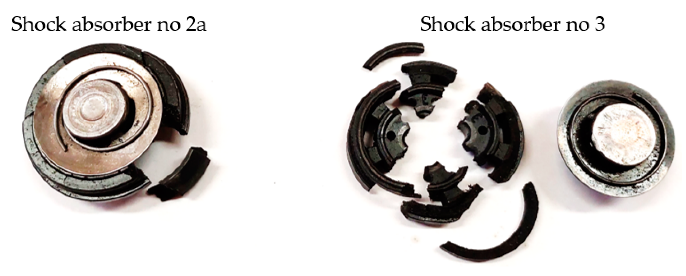
The used shock absorber is in working condition; however, it has a reduced damping coefficient of approximately 24% in the rebound range. Larger differences were seen to occur during the compression. The check valve was found to already open at a force of around 100 N and the damping ratio reduces to around 225 N·s/m. When the check valve failed, the damping practically remains constant (around 280 N-s/m)—a slight increase is visible only for speeds above 0.25 m/s. After testing the defective shock absorber (3), the cause of its malfunction was checked. A lack of pressure in the gas section was noted and also, a broken ring within the check valve was found. The extent of its damage was greater than in shock absorber 2 (Figure 4). In addition, traces of overheating of the shock absorber (black burnt oil), as well as contamination in the lower part of the shock absorber (around the valve) were found. This type of damage was most likely caused by exhaustion of the shock absorber stroke and the piston hitting the valve.
3.2. Shock Absorber Heating
Figure 5 shows the distributions on the surface of the new shock absorber as it heats up. These were obtained during a test for which the displacement amplitude was 80 mm and the frequency was 1 Hz. Within 8 min of testing, the temperature increased from 25 to over 130 °C. For tests conducted at lower speeds (lower amplitude or frequency of displacement), smaller differences in temperature distributions were noted.
In order to observe the differences more closely, a temperature graph was drawn up along the shock absorber cylinder (in its axis). It is shown in Figure 6.
During the initial period of operation, more heating is observed in the lower part of the shock absorber. This is the result of the warm oil flowing from the inner chamber to the outer chamber. Then, due to the friction of the piston rod against the seal, the upper section of the shock absorber cylinder also heats up. The greatest differences in temperature distribution were observed between minute 2 and 3. They exceed by 13 °C (the coldest being the middle part of the cylinder).
3.3. Shock Absorber Cooling
The shock absorber’s ability to dissipate vibration energy depends, among other issues, on its ability to dissipate heat. If it is too small, this leads to excessive heating of the shock absorber and increases the likelihood of damage (mainly to the seals, which lead to unsealing of the chambers). The ability to dissipate heat depends on the geometry and the type of materials used (including paintwork), but also on the purity of the surface. This can be defined by determining the cooling curve of the shock absorber (Figure 7).
The heat exchange can be determined by Newton’s law of cooling. The temperature change is defined by relation (1) [25]:
where:
T(t)/dt = −k·(To − Ta),
- Ta—ambient temperature (°C),
- To—initial temperature (°C),
- t—time (s),
- κ—cooling constant (1/s).
After the integration of the equation (1), we obtain an expression that can be written in the form (2):
T(t) = Ta − (To − Ta)·exp(−κ t)
Using the results shown in Figure 7, the value of κ equals 0.00071 s−1. The cooling constant κ may also be defined by the Equation (3):
where:
κ = (λ⋅A)/(m⋅c),
- λ—equivalent heat transfer coefficient (W/(m2·K)),
- A—heat exchange surface area (m2),
- m—mass (kg),
- c—specific heat (J/(kg·K)).
Assuming that the quantities shown above do not change along with the temperature, it is possible to determine the steady-state operating temperature for other ambient temperatures. This is conducted by using the equilibrium conditions between external work and dissipated energy (heat flux) (4).
where:
Q = Ed/tc = A·λ·(T − Ta),
- Q—heat flux (W),
- Ed—energy dissipated during one cycle (J),
- tc—duration of one operating cycle (s).
The lack of a linear relationship between the energy dissipated during one cycle (at a constant value of amplitude and frequency of movement) and the temperature requires an iterative solution using the relationship shown in Figure 9.
3.4. An Investigation of the Influence of Temperature on Damping Characteristics
In the last stage, the influence of the temperature on the ability of the damper to dissipate vibration energy was specified. For this purpose, a test was conducted from the initial temperature until the steady-state value temperature was established at a given excitation. The tests were conducted for an amplitude of 60 mm and a frequency of 1 Hz (from a temperature of 27 °C), and a frequency of 0.5 Hz for an initial temperature of −30 °C. The reduction in excitation parameters compared to previous tests was due to a reduction in the probability of shock absorber failure. In the test performed for shock absorber 2 at an amplitude of 80 mm and a frequency of 1 Hz, the valve failed at its initial stage (after forty cycles). This manifested itself in a sharp reduction in resistance forces. Figure 8 summarises the force–displacement characteristics obtained when the shock absorber was heated.
The most rapid changes in resistance forces are observed for negative operating temperatures. Due to the rapid increase in viscosity of the oil at negative temperatures, the force obtained at −30 °C is 2.5 times greater than for 20 °C. In comparison, a temperature change from 30 °C to 130 °C reduces the maximum resistance force by only about 11%.
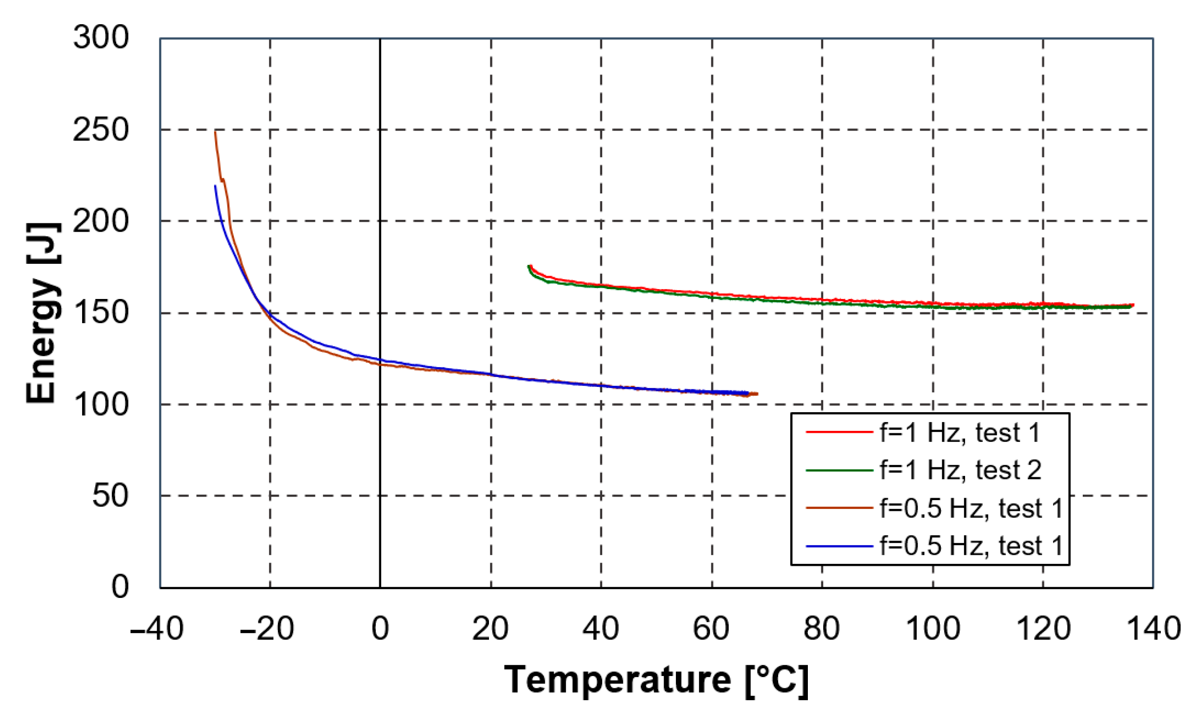
Based on the recorded force–displacement characteristics, the amount of energy dissipated to the environment Ed during each duty cycle was calculated [16]:
Ed = ∮Fdx
The results are shown in Figure 9. For a frequency of 0.5 Hz, thermodynamic equilibrium (equilibrium between the work of the external force and the heat dissipated to the environment) was reached at 68 °C (dissipating approximately 106 J per cycle). For a frequency of 1 Hz, the values of 136 °C and 158 J were obtained, respectively. It can be concluded that the amount of dissipated energy is practically independent of the frequency of the displacement of the shock absorber piston. This is because it is primarily dependent on the rate of change of oil viscosity. The values of energy dissipation rates depending on the temperature are shown in Table 2.
The amount of energy dissipated per cycle decreases non-linearly with the temperature. The fastest changes are again observed for low temperatures. For temperatures above 20 °C, a linear change at a rate of approximately −0.2 J/°C can be assumed.
4. Discussion
The paper presents issues related to the influence of the technical condition and the temperature on shock absorber damping characteristics. For a used shock absorber, for which the Eusama indicator value was E = 58%., the determined value of the damping coefficient in the rebound range was approximately 24% lower compared to a new shock absorber. Shock absorber 3, sold as a used shock absorber in a working condition, was found to be serviceless. It is important to be aware that the performance of a shock absorber has a direct impact on the driving safety. Regulations in many countries prohibit the reinstallation of safety-relevant parts; thus, the use of second-hand shock absorbers is not permitted.
During its intensive use, a shock absorber heats up rapidly. A contaminated outer surface can impede proper heat dissipation, leading to overheating of the shock absorber. The lower part of the shock absorber is the one heating up the fastest.
The dissipation of heat to the environment (reduction of the temperature of the shock absorber) is well described by Newton’s cooling law. For the shock absorber tested, the cooling constant was 0.00071 1/s.
The change in temperature has a direct effect on the change in viscosity of the oil and thus, on the resistance forces of the shock absorber. The greatest impact is observed for negative temperatures. For the tested shock absorber, the force obtained at −30 °C was approximately 2.5 higher than at 20 °C. The intense operation at low temperatures can result in the failure of the damper valves. At sub-zero temperatures, the displacement of the piston relative to the cylinder even at low speeds rapidly generates high-resistance forces. Excessively high damping forces increase the forces transmitted to the vehicle body and also, increase the possibility of the wheels pulling away from the road surface.
A limitation for the tests conducted was the method of measuring the temperature at the surface of the shock absorber. In further research, it might be important to additionally monitor the oil temperature in both the inner and outer chambers. This would enable the process of heat transfer to the environment to be analysed.
In addition, tests with different excitation parameters at low, stabilised temperatures could provide valuable results. However, such tests require the use of a climate chamber.
Funding
This work was financed by Military University of Technology under research project UGB 879/2021.
Institutional Review Board Statement
Not applicable.
Informed Consent Statement
Not applicable.
Data Availability Statement
Not applicable.
Conflicts of Interest
The author declares no conflict of interest.
References
- Hryciów, Z.; Krasoń, W.; Wysocki, J. The experimental tests on the friction coefficient between the leaves of the multi-leaf spring considering a condition of the friction surfaces. Eksploat. I Niezawodn.-Maint. Reliab. 2018, 20, 682–688. [Google Scholar] [CrossRef]
- Hryciów, Z.; Krasoń, W.; Wysocki, J. Evaluation of the influence of friction in a multi-leaf spring on the working conditions of a truck driver. Eksploat. I Niezawodn.–Maint. Reliab. 2021, 23, 422–429. [Google Scholar] [CrossRef]
- Tran, V.-K.; Han, P.-W.; Chun, Y.-D. Design of a 120W Electromagnetic Shock Absorber for Motorcycle Applications. Appl. Sci. 2022, 12, 8688. [Google Scholar] [CrossRef]
- Zhao, G.; Ma, Y.; Yang, Z.; Wang, Q.; Li, Y. Friction mechanism and experimental investigation of the response-amplified friction damper. Struct. Control Health Monit. 2022, 29, e2953. [Google Scholar] [CrossRef]
- Teng, G.; Zhao-Dong, X.; Yuan, F.G. Predictive model of dynamic mechanical properties of VE damper based on acrylic rubber–graphene oxide composites considering aging damage. J. Aerosp. Eng. 2022, 35, 04021132. [Google Scholar] [CrossRef]
- Dixon, J.C. The Shock Absorber Handbook, 2nd ed.; Professional Engineering Publishing Ltd. and John Wiley and Sons, Ltd.: West Sussex, UK, 2007. [Google Scholar]
- Yu, B.; Wang, Z.; Wang, G.; Zhao, J.; Zhou, L.; Zhao, J. Investigation of the Suspension Design and Ride Comfort of an Electric Mini Off-Road Vehicle. Adv. Mech. Eng. 2019, 11, 1–10. [Google Scholar] [CrossRef] [Green Version]
- Skačkauskas, P.; Žuraulis, V.; Vadluga, V.; Nagurnas, S. Development and verification of a shock absorber and its shim valve model based on the force method principles. Eksploat. I Niezawodn.-Maint. Reliab. 2017, 19, 126–133. [Google Scholar] [CrossRef]
- Rana, J.H.; Gajjar, S.R.; Patel, A.K. Experimental Analysis and Heat Transfer Study Of Damping Fluid In Shock Absorber Operation. Int. J. Eng. Dev. Res. (IJEDR) 2014, 2, 2939–2947. Available online: https://www.ijedr.org/papers/IJEDR1403009 (accessed on 7 November 2022).
- Liang, L.; Liang, T.; Yunqing, Z.; Jie, Z. Twin Tube Shock Absorber Thermo-Mechanical Coupling Simulation. Adv. Mater. Res. 2012, 566, 669–675. [Google Scholar] [CrossRef]
- Pracny, V.; Meywerk, M.; Lion, A. Full vehicle simulation using thermomechanically coupled hybrid neural network shock absorber model. Veh. Syst. Dyn. 2008, 46, 229–238. [Google Scholar] [CrossRef]
- Xie, F.; Cao, J.; Ding, E.; Wan, K.; Yu, X.; Ke, J.; Gao, K. Temperature rise characteristics of the valve-controlled adjustable damping shock absorber. Mech. Ind. 2020, 21, 1–11. [Google Scholar] [CrossRef]
- Pavlov, N. Influence of shock absorber temperature on vehicle ride comfort and road holding. MATEC Web Conf. 2017, 133, 1–6. [Google Scholar] [CrossRef] [Green Version]
- Patel, D.R.; Rathod, P.P.; Sorathiya, A.S. Heat Transfer Study of Damping Fluid and Improvement of Air-Gap in Shock Absorber Operation. Int. J. Eng. Res. Technol. (IJERT) 2012, 1, 1–7. [Google Scholar]
- Howard, C.; Sergiienko, N.Y.; Gallasch, G. Monitoring the age of vehicle shock absorbers. In Proceedings of the International Conference on Science and Innovation for Land Power 2018 (ICSILP 2018), Adelaide, Australia, 5–6 September 2018; pp. 1–5. [Google Scholar]
- Jurecki, R.S. The influence of temperature on the damping value of shock absorbers determined by the Eusama method. Sci. J. Marit. Univ. Szczec. 2019, 60, 34–40. [Google Scholar]
- Konieczny, Ł.; Filipczyk, J. Analysis of the possibility of using the phase angle in the Eusama method as an additional diagnostic parameter in the assessment of the technical condition of the vehicle suspension system. Diagnostyka 2022, 23, 2022414. [Google Scholar] [CrossRef]
- Hryciów, Z.; Rybak, P.; Gieleta, R. The influence of temperature on the damping characteristic of hydraulic shock absorbers. Eksploat. I Niezawodn.–Maint. Reliab. 2021, 23, 346–351. [Google Scholar] [CrossRef]
- Shu, N.; Gu, H.; Liu, H. Analysis of temperature effect on damping characteristics of landing gear shock absorber. In Proceedings of the International Conference on Aviation Safety and Information Technology (ICASIT 2020), Weihai, China, 14–16 October 2020. [Google Scholar] [CrossRef]
- Jastrzębski, Ł.; Sapiński, B.; Kozieł, A. Automotive MR Shock Absorber Behaviour Considering Temperature Changes: Experimental Testing and Analysis. Acta Mech. Et Autom. 2020, 14, 22–28. [Google Scholar] [CrossRef]
- McKee, M.; Gordaninejad, F.; Wang, X. Effects of temperature on performance of compressible magnetorheological fluid suspension systems. J. Intell. Mater. Syst. Struct. 2018, 29, 41–51. [Google Scholar] [CrossRef] [Green Version]
- Alonso, M.; Comas, Á. Thermal model of a twin-tube cavitating shock absorber. Proc. Inst. Mech. Eng. Part D J. Automob. Eng. 2008, 222, 1955–1964. [Google Scholar] [CrossRef]
- Cao, J.; Xie, F.; Ding, E.; Zhang, X.; Qian, P.; He, K. Temperature Characteristics of the Valve-controlled Shock Absorber. In Proceedings of the IEEE 8th International Conference on Fluid Power and Mechatronics (FPM), Wuhan, China, 10–13 April 2019; pp. 666–670. [Google Scholar] [CrossRef]
- Sheikh Al-Shabab, A.A.; Grenko, B.; Vitlaris, D.; Tsoutsanis, P.; Antoniadis, A.F.; Skote, M. Numerical Investigation of Orifice Nearfield Flow Development in Oleo-Pneumatic Shock Absorbers. Fluids 2022, 7, 54. [Google Scholar] [CrossRef]
- Sobieski, W. Termodynamika w Eksperymentach; Uniwersytet Warmińsko-Mazurski: Olsztyn, Poland, 2015. [Google Scholar]
Figure 1.
Testing stand: (a) view of the tested shock absorbers; (b) shock absorber mounted on the stand.
Figure 1.
Testing stand: (a) view of the tested shock absorbers; (b) shock absorber mounted on the stand.

Figure 2.
Characteristics of the shock absorber: (a) force–displacement; (b) force–velocity.

Figure 3.
Characteristics of the shock absorber: 1—new, 2—used functional, 2a—used defective, 3—defective.
Figure 3.
Characteristics of the shock absorber: 1—new, 2—used functional, 2a—used defective, 3—defective.

Figure 4.
Defective check valves.

Figure 5.
Temperature distributions on the surface of the shock absorber (temperature in (°C)).

Figure 6.
Temperature changes at the surface (along the shock absorber axis).

Figure 7.
Shock absorber cooling curve.

Figure 8.
The influence of temperature on shock absorber force–displacement characteristics: (a) A = 60 mm, f = 1 Hz; (b) A = 60 mm, f = 0.5 Hz.
Figure 8.
The influence of temperature on shock absorber force–displacement characteristics: (a) A = 60 mm, f = 1 Hz; (b) A = 60 mm, f = 0.5 Hz.

Figure 9.
Energy dissipated in one cycle.


Table 1.
Damping coefficient of the new shock absorber.
| Velocity [m/s] | Damping Coefficient c [N·s/m] |
|---|---|
| −0.5 ÷ −0.05 | 500 |
| −0.05 ÷ 0.05 | 6800 |
| 0.05 ÷ 0.5 | 2300 |
Table 2.
Temperature dependence of the energy dissipation rate.
| Temperature [°C] | Energy Dissipation Rates [J/°C] |
|---|---|
| −20 | −2.14 |
| 0 | −0.564 |
| 20 | −0.325 |
| 60 | −0.192 |
| 100 | −0.122 |
| 130 | −0.091 |
Publisher’s Note: MDPI stays neutral with regard to jurisdictional claims in published maps and institutional affiliations. |
© 2022 by the author. Licensee MDPI, Basel, Switzerland. This article is an open access article distributed under the terms and conditions of the Creative Commons Attribution (CC BY) license (https://creativecommons.org/licenses/by/4.0/).
Share and Cite
MDPI and ACS Style
Hryciów, Z. An Investigation of the Influence of Temperature and Technical Condition on the Hydraulic Shock Absorber Characteristics. Appl. Sci. 2022, 12, 12765. https://doi.org/10.3390/app122412765
AMA Style
Hryciów Z. An Investigation of the Influence of Temperature and Technical Condition on the Hydraulic Shock Absorber Characteristics. Applied Sciences. 2022; 12(24):12765. https://doi.org/10.3390/app122412765
Chicago/Turabian StyleHryciów, Zdzisław. 2022. "An Investigation of the Influence of Temperature and Technical Condition on the Hydraulic Shock Absorber Characteristics" Applied Sciences 12, no. 24: 12765. https://doi.org/10.3390/app122412765
Note that from the first issue of 2016, this journal uses article numbers instead of page numbers. See further details here.