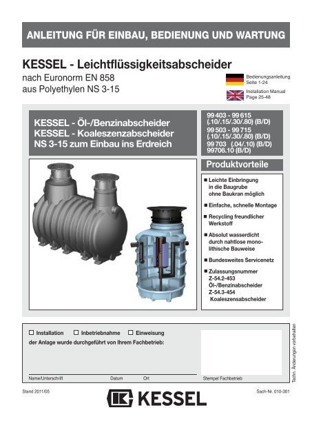
KESSEL - Leichtflüssigkeitsabscheider
KESSEL - Leichtflüssigkeitsabscheider
KESSEL - Leichtflüssigkeitsabscheider

Erfolgreiche ePaper selbst erstellen
Machen Sie aus Ihren PDF Publikationen ein blätterbares Flipbook mit unserer einzigartigen Google optimierten e-Paper Software.
ANLEITUNG FÜR EINBAU, BEDIENUNG UND WARTUNG<br />
<strong>KESSEL</strong> - <strong>Leichtflüssigkeitsabscheider</strong><br />
nach Euronorm EN 858<br />
aus Polyethylen NS 3-15<br />
Bedienungsanleitung<br />
Seite 1-24<br />
Installation Manual<br />
Page 25-48<br />
<strong>KESSEL</strong> - Öl-/Benzinabscheider<br />
<strong>KESSEL</strong> - Koaleszenzabscheider<br />
NS 3-15 zum Einbau ins Erdreich<br />
99 403 - 99 615<br />
(.10/.15/.30/.80) (B/D)<br />
99 503 - 99 715<br />
(.10/.15/.30/.80) (B/D)<br />
99 703 (.04/.10) (B/D)<br />
99706.10 (B/D)<br />
Produktvorteile<br />
Leichte Einbringung<br />
in die Baugrube<br />
ohne Baukran möglich<br />
Einfache, schnelle Montage<br />
Recycling freundlicher<br />
Werkstoff<br />
Absolut wasserdicht<br />
durch nahtlose mono -<br />
lithische Bauweise<br />
Bundesweites Servicenetz<br />
Zulassungsnummer<br />
Z-54.2-453<br />
Öl-/Benzinabscheider<br />
Z-54.3-454<br />
Koaleszensabscheider<br />
Installation Inbetriebnahme Einweisung<br />
der Anlage wurde durchgeführt von Ihrem Fachbetrieb:<br />
Name/Unterschrift Datum Ort<br />
Stempel Fachbetrieb<br />
Techn. Änderungen vorbehalten<br />
Stand 2011/05<br />
Sach-Nr. 010-301
1. Sicherheitshinweise<br />
Das Personal für Einbau, Montage, Bedienung, Wartung und Reparatur muß die entsprechende<br />
Qualifikation für diese Arbeiten aufweisen. Verantwortungsbereich, Zuständigkeit<br />
und die Überwachung des Personals müssen durch den Betreiber genau geregelt sein.<br />
Die Betriebssicherheit der gelieferten Anlage ist nur bei bestimmungsgemäßer Verwendung<br />
gewährleistet. Die Grenzwerte der technischen Daten dürfen auf keinen Fall überschritten<br />
werden.<br />
Bei Einbau, Montage, Bedienung, Wartung und Reparatur der Anlage sind die Unfallverhütungsvorschriften<br />
und die in Frage kommenden Normen und Richtlinien zu beachten!<br />
Dies sind u.a.:<br />
• Unfallverhütungsvorschriften<br />
- Bauarbeiten BGV C22<br />
- Abwassertechnische Anlagen GUV-V C5<br />
• Sicherheitsregeln für Arbeiten in umschlossenen Räumen von abwassertechnischen<br />
Anlagen GUV-R 126<br />
• Umgang mit biologischen Arbeitsstoffen in abwassertechnischen Anlagen GUV-R 145<br />
• Richtlinien für Arbeiten in Behältern und engen Räumen BGR 117<br />
• Normen<br />
- Baugruben und Gräben - Böschungen, Verbau, Arbeitsraumbreiten DIN 4124<br />
- Verlegung und Prüfung von Abwasserleitungen und -kanälen DIN EN 1610<br />
• Arbeitshilfe für Sicherheit und Gesundheitsschutz in abwassertechnischen Anlagen.<br />
SPEZIFISCHE<br />
GEFÄHRDUNGEN!<br />
• Gefahren durch Gase und Dämpfe wie Erstickungsgefahr, Vergiftungsgefahr und Explosionsgefahr<br />
• Absturzgefahr<br />
• Ertrinkungsgefahr<br />
• Keimbelastung und fäkalienhaltige Abwässer<br />
• Hohe physische und psychische Belastungen bei Arbeiten in tiefen, engen oder dunklen<br />
Räumen<br />
• und weitere<br />
WARNUNG !<br />
Bei Nichtbeachtung der Bedienungsanleitung können erhebliche Sachschäden, Körperverletzungen<br />
oder tödliche Unfälle die Folge sein.<br />
ACHTUNG !<br />
Die Anlage stellt eine Komponente einer Gesamtanlage dar. Beachten Sie deshalb auch<br />
die Bedienungsanleitungen der Gesamtanlage und der einzelnen Komponenten. Bei jeder<br />
Montage, Wartung, Inspektion und Reparatur an einer der Komponenten ist immer die Gesamtanlage<br />
außer Betrieb zu setzen und gegen Wiederinbetriebnahme zu sichern.<br />
Umbau oder Veränderungen der Anlage sind nur in Absprache mit dem Hersteller zu tätigen.<br />
Originalersatzteile und vom Hersteller zugelassenes Zubehör dienen der Sicherheit.<br />
Die Verwendung anderer Teile kann die Haftung für die daraus entstehenden Folgen aufheben.<br />
2
Inhaltsverzeichnis<br />
1. Sicherheitshinweise ................................................................................. Seite 2<br />
2. Einsatzbereich 2.1 Einsatzbereich.......................................................... Seite 4<br />
2.2 Anlagenbeschreibung ............................................. Seite 5<br />
2.3 Funktionsbeschreibung............................................ Seite 5<br />
3. Technische Daten 3.1 Einbauvorschlag Öl-/Benzinabscheider............................. Seite 6<br />
3.2 Maßzeichnung Öl-/Benzinabscheider................................ Seite 6<br />
3.3 Einbauvorschlag Koaleszenzabscheider Zisterne................. Seite 7<br />
3.4 Maßzeichnung Koaleszenzabscheider Zisterne.................... Seite 7<br />
3.5 Abbildung Koaleszenzabscheider Schacht LW 1000, NS 3 ........ Seite 8<br />
3.6 Maßzeichnung Koaleszenzabscheider Schacht LW 1000, NS 3.. Seite 8<br />
3.7 Maßzeichnung Koaleszenzabscheider Schacht LW 1000, NS 6.. Seite 8<br />
4. Verpackung, Transport 4.1 Verpackung............................................................... Seite 9<br />
und Lagerung 4.2 Transport .................................................................. Seite 9<br />
4.3 Lagerung.................................................................. Seite 9<br />
5. Einbau und Montage 5.1 Einbauvoraussetzungen........................................... Seite 10<br />
5.2 Verfüllmaterial .......................................................... Seite 11<br />
5.3 Baugrube.................................................................. Seite 11<br />
5.4 Prüfungen vor dem Einbau ...................................... Seite 11<br />
5.5 Einbau...................................................................... Seite 11<br />
5.6 Warnanlage.............................................................. Seite 13<br />
5.7 Öl- und Schlammabsaugung.................................... Seite 14<br />
6. Inbetriebnahme 6.1 Anlage in Betriebsbereitschaft setzen...................... Seite 16<br />
6.2 Einweisung / Übergabe ............................................ Seite 16<br />
6.3 Übergabeprotokoll.................................................... Seite 16<br />
7. Entsorgung .............................................................................................. Seite 16<br />
8. Eigenkontrolle, Wartung und Überprüfung .............................................................................................. Seite 18<br />
9. Ersatzteile und Zubehör .............................................................................................. Seite 20<br />
10. Gewährleistung .............................................................................................. Seite 21<br />
11. Anlagenpaß/Werksabnahme .............................................................................................. Seite 22<br />
Übergabeprotokoll .............................................................................................. Seite 23<br />
3
Sehr geehrter Kunde,<br />
wir freuen uns, daß Sie sich für ein Produkt von <strong>KESSEL</strong> entschieden haben.<br />
Die gesamte Anlage wurde vor Verlassen des Werkes einer strengen Qualitätskontrolle unterzogen. Prüfen Sie bitte dennoch<br />
sofort, ob die Anlage vollständig und unbeschädigt bei Ihnen angeliefert wurde. Im Falle eines Transportschadens<br />
beachten Sie bitte die Anweisungen in Kapitel „Gewährleistungen“ dieser Anleitung.<br />
Diese Einbau-, Bedienungs- und Wartungsanleitung enthält wichtige Hinweise, die bei Einbau, Montage, Bedienung, Wartung<br />
und Reparatur zu beachten sind. Vor allen Arbeiten an der Anlagen müssen der Betreiber sowie das zuständige Fachpersonal<br />
diese Anleitung sorgfälltig lesen und befolgen.<br />
Wichtig! Die in dieser Anleitung für Einbau, Bedienung und Wartung genannten Hinweise, Werte, Vorgaben etc. sind bedingt<br />
durch die geprüfte Statik, nicht auf andere Produkte übertragbar.<br />
<strong>KESSEL</strong> AG<br />
2. Einsatzbereich<br />
2. Allgemeines<br />
2.1 Einsatzbereich<br />
Die Abscheider sind unter festgelegten Bedingungen, siehe<br />
Kapitel „Einbau und Montage“, ausschließlich zum Erdeinbau<br />
im Freien oder unterhalb der Bodenplatte in gut belüfteten<br />
Räumen bestimmt.<br />
2.1.1 Öl-/Benzinabscheider gem. Abscheiderklasse II<br />
Die Abscheider können eingesetzt werden:<br />
a) zur Behandlung von mit Leichtflüssigkeiten verunreinigtem<br />
Regenwasser von befestigten Flächen z.B. Tankstellen,<br />
Öllager und Ölumschlagplätzen, Parkplätzen und Straßen<br />
in Wasserschutzgebieten<br />
b) als Rückhalteeinrichtung für Leichtflüssigkeiten von Anlagen<br />
und Flächen, in bzw. auf denen mit Leichtflüssigkeiten<br />
umgegangen wird, z.B. Tankstellen, Öllager und Ölumschlagplätzen<br />
c) zur Vorabscheidung von Leichtflüssigkeiten aus Abwasser,<br />
das einer weitergehenden Behandlung in nachgeschalteten<br />
innerbetrieblichen Abwasserbehandlungsanlagen unterzogen<br />
wird.<br />
In den Fällen a) und b) ist das Ablaufwasser der Abscheider<br />
zur Einleitung in die öffentlichen Entwässerungsanlagen bestimmt.<br />
Soweit das Ablaufwasser in ein Gewässer eingeleitet werden<br />
soll, ist dies im Einzelfall nur möglich nach Klärung der Zulässigkeit<br />
einer solchen Einleitung bzw. der ggf. erforderlichen<br />
zusätzlichen Anforderungen mit der örtlichen zuständigen<br />
Wasserbehörde.<br />
Bei der Behandlung von mit Leichtflüssigkeiten verunreinigtem<br />
Schmutzwasser (gewerbliches Abwasser) oder von Abwasser<br />
aus Anwendungsbereichen des Anhangs 49 der Abwasserverordnung<br />
kann die Einhaltung eines Grenzwertes<br />
für Kohlenwasserstoffe von 20 mg/l nicht als eingehalten gelten.<br />
2.1.2 Öl-/Benzinabscheider gem. Abscheiderklasse I<br />
Abscheider für Leichtflüssigkeiten mit Koaleszenzeinrichtung<br />
können eingesetzt werden:<br />
a) zur Behandlung von mit Leichtflüssigkeiten verunreinigtem<br />
Regenwasser von befestigten Flächen z.B. Tankstellen,<br />
Öllagern und Ölumschlagplätzen sowie von Parkplätzen<br />
und Straßen in Wasserschutzgebieten,<br />
b) als Rückhalteeinrichtung für Leichtflüssigkeiten zur Absicherung<br />
von Anlagen und Flächen, in bzw. auf denen mit<br />
Leichtflüssigkeiten umgegangen wird, z.B. Tankstellen, Öllagern<br />
und Ölumschlagplätzen,<br />
c) zur Behandlung von mit Leichtflüssigkeiten verunreinigtem<br />
Schmutzwasser (gewerbliches Abwasser), das unter<br />
Berücksichtigung der Betriebsbedingungen bei industriellen<br />
Prozessen, der Reinigung von ölverschmutzten Teilen<br />
und der Reinigung ölverschmutzter Bodenflächen (ausgenommen<br />
Werkstattböden) anfällt,<br />
d) zur Behandlung von Abwasser, das unter Berücksichtigung<br />
der Betriebsbedingungen bei der maschinellen Fahrzeugreinigung<br />
(Teilstrom: Ausschleusung vor der Kreislaufanlage<br />
mit anschließender Einleitung), bei der manuellen<br />
Reinigung (Fahrzeugoberwäsche, Motorwäsche, Unterbodenwäsche,<br />
Chassisreinigung in Waschhallen sowie<br />
auf SB- oder betrieblichen Waschplätzen - ausgenommen<br />
Reinigung ölverschmierter Werkstattböden -) und bei der<br />
Entwässerung von Flächen zur Annahme, Eingangslagerung,<br />
Trockenlegung, Demontage und Verdichtung von<br />
Altfahrzeugen anfällt,<br />
e) zur Vorabscheidung von Leichtflüssigkeiten aus Abwasser,<br />
das einer weitergehenden Behandlung in nachgeschalteten<br />
innerbetrieblichen Abwasserbehandlungsanlagen unterzogen<br />
wird.<br />
4
2. Einsatzbereich<br />
In den Fällen a) bis d) ist das Ablaufwasser der Abscheider<br />
zur Einleitung in die öffentlichen Entwässerungsanlagen bestimmt.<br />
Soweit das Ablaufwasser in ein Gewässer eingeleitet werden<br />
soll, ist dies im Einzelfall nur möglich nach Klärung der Zulässigkeit<br />
einer solchen Einleitung bwz. der ggf. erforderlichen<br />
zusätzlichen Anforderungen mit der örtlich zuständigen Wasserbehörde.<br />
Abscheider, die im Fall d) eingesetzt werden, sind in Anlagen<br />
zur Begrenzung von Kohlenwasserstoffen in mineralölhaltigem<br />
Abwasser im Sinne von Teil E Absatz 2 des Anhangs 49<br />
der Abwasserverordnung.<br />
Der in den Fällen c) und d) wasserrechtlich geforderte Wert<br />
für Kohlenwasserstoffe von 20 mg/l gilt als eingehalten.<br />
2.2 Anlagenbeschreibung<br />
Die Abbildung zeigt einen erdeingebauten Benzinabscheider-Zisterne<br />
Klasse A/B.<br />
<br />
<br />
Ablaufstelle ohne Geruchsverschluß<br />
<strong>Leichtflüssigkeitsabscheider</strong><br />
Zulauf mit Geruchsverschluß<br />
Ablauf mit selbsttätigen Abschluß<br />
Führungsrohr<br />
Schwimmer<br />
Aufsatzstück<br />
Abdeckung<br />
Probenahmeschacht<br />
Rückstausicherung<br />
<br />
<br />
<br />
<br />
<br />
<br />
<br />
<br />
2.3 Funktionsbeschreibung<br />
Die Abscheider bewirken eine Trennung des Abwassers von<br />
Leichtflüssigkeiten und Schlamm aufgrund der Schwerkraft.<br />
Unter Leichtflüssigkeiten versteht man Flüssigkeiten mineralischen<br />
Ursprungs mit einer Dichte ≤ 0,95 g/cm 3 , die im Wasser<br />
nicht oder nur gering löslich und unverseifbar sind. Nicht<br />
dazu gehören stabile Emulsionen, Fette und Öle pflanzlichen<br />
oder tierischen Ursprungs. Leichtflüssigkeiten schwimmen<br />
im Abscheideraum auf und sammeln sich an der Oberfläche<br />
an. Schlämme, die schwerer sind als Wasser, sinken zu<br />
Boden und bilden eine Schlammschicht.<br />
Koaleszenzabscheider funktionieren wie Öl-/Benzinabscheider<br />
nach dem Schwerkraftprinzip. Zur Erhöhung der Abscheideleistung<br />
befindet sich zusätzlich noch ein Koaleszenzeinsatz<br />
im Behälter. Dieser zylinderförmige Einsatz hat zwei<br />
Funktionen. Zum einen beeinflußt er die Strömung im Abscheider,<br />
zum anderen „filtert“ er das gesamte Abwasser<br />
durch das Koaleszenzmaterial.<br />
Wird dieses Filtergewebe von ölhaltigem Abwasser durchströmt,<br />
lagern sich feinste, über die Schwerkraft nicht mehr<br />
abscheidbare, Öltröpfchen an das Koaleszenzmaterial an<br />
und vereinigen sich dort zu großen Öltropfen. Haben diese<br />
eine auftriebssichere Größe erreicht, lösen sie sich vom Filtermaterial<br />
und steigen zur Oberfläche auf.<br />
<strong>Leichtflüssigkeitsabscheider</strong> sind serienmäßig mit einem<br />
selbsttätigen Verschluß ausgestattet.<br />
Wird die maximale Ölspeichermenge überschritten, verschließt<br />
diese Einrichtung den Ablauf zur Kanalisation. Der<br />
Austritt von Leichtflüssigkeiten in die Kanalisation wird verhindert.<br />
Diese Sicherung besteht aus einem mit Wasser gefüllten<br />
Führungsrohr in dem sich ein Schwimmer befindet.<br />
Der Schwimmer ist so tariert, dass er im Wasser schwimmt<br />
und in der Leichflüssigkeit (bis zu einer Dichte von 0,95 g/cm 3 )<br />
sinkt. Wird die maximale Ölspeichermenge erreicht, gelangt<br />
Öl durch seitliche Öffnungen in das Schwimmer-Führungsrohr.<br />
Der Schwimmer sinkt dann nach unten und verschließt<br />
zuverlässig den Ablauf des Abscheiders.<br />
Der selbsttätige Verschluss eines Abscheiders ist eine „Notbremse“.<br />
Löst er im Havariefall aus, ist der Abscheider außer<br />
Betrieb zu nehmen und zu warten.<br />
5
3. Technische Daten<br />
3.1 Einbauvorschlag: <strong>KESSEL</strong>-Öl-/Benzinabscheider-Zisterne<br />
Abbildung zeigt <strong>KESSEL</strong>-Öl-/Benzinabscheider-Zisterne Klasse II mit Abdeckung Klasse B und Probenahmeschacht<br />
3.2 Maßzeichnung<br />
DN 150: T-TEÜ = 155 mm<br />
DN 200: T-TEÜ = 180 mm<br />
T-TEÜ = Tiefe Erdüberdeckung<br />
Klasse D: 700 mm ≤ TEÜ ≤ 1.500 mm<br />
Klasse A/B: 700 mm ≤ TEÜ ≤ 1.800 mm<br />
6
3. Technische Daten<br />
3.3 Einbauvorschlag: <strong>KESSEL</strong>-Koaleszenzabscheider Zisterne<br />
Abbildung zeigt <strong>KESSEL</strong>-Koaleszenzabscheider-Zisterne Klasse I mit Abdeckung Klasse B und Probenahmeschacht<br />
3.4 Maßzeichnung Zisterne<br />
DN 150: T-TEÜ = 155 mm<br />
DN 200: T-TEÜ = 180 mm<br />
T-TEÜ = Tiefe Erdüberdeckung<br />
Klasse D: 700 mm ≤ TEÜ ≤ 1.500 mm<br />
Klasse A/B: 700 mm ≤ TEÜ ≤ 1.800 mm<br />
7
3. Technische Daten<br />
3.5 Abbildung: <strong>KESSEL</strong>-Koaleszenzabscheider<br />
Schacht LW 1000, NS 3<br />
3.6 Maßzeichnung <strong>KESSEL</strong>-Koaleszenzabscheider<br />
Schacht LW 1000, NS 3<br />
NS<br />
Durchmesser<br />
Ø<br />
3 800 100 1100 Ø 545 995 1105 1055 790 200 110 175 B 99703.04B<br />
3 800 100 1100 Ø 545 995 1105 1055 790 200 110 205 D 99703.04D<br />
3 1600 100 1100 Ø 545 995 1605 1555 1390 200 110 190 B 99703.10B<br />
3 1600 100 1100 Ø 545 995 1605 1555 1390 200 110 220 D 99703.10D<br />
ø<br />
3.7 Maßzeichnung <strong>KESSEL</strong>-Koaleszenzabscheider LW 1000, NS 6 (mit vorgeschaltetem Schlammfang)<br />
ø<br />
Durchmesser<br />
NS<br />
Ø<br />
6 1000 150 1100 Ø 560 1010 1090 1020 1580 200 110 305 B 99706.10B<br />
6 1000 150 1100 Ø 560 1010 1090 1020 1580 200 110 338 D 99706.10D<br />
8
4. Verpackung, Transport und Lagerung<br />
Das Kapitel Sicherheitshinweise ist zu beachten!<br />
4.1 Verpackung<br />
Eine Verpackung der Behälter zum Zwecke des Transports<br />
bzw. der Lagerung ist bei Beachtung der nachfolgenden<br />
Punkte nicht notwendig.<br />
Hinweis: Der Eintrag von Fremdkörpern (Schmutz, Staub<br />
etc.) in den Abscheider ist zu vermeiden. Ggf. sind an allen<br />
Öffnungen Abdeckungen anzubringen.<br />
4.2 Transport<br />
l Der Transport ist nur von solchen Firmen durchzuführen,<br />
die über fachliche Erfahrungen, geeignete Geräte, Einrichtungen<br />
und Transportmittel sowie ausreichend geschultes<br />
Personal verfügen.<br />
l Die Behälter müssen so transportiert werden, daß sie<br />
nicht unzulässig belastet werden und daß eine Lageveränderung<br />
während des Transports ausgeschlossen ist. Im Falle<br />
einer Verspannung ist diese so vorzunehmen, daß eine Beschädigung<br />
der Behälter ausgeschlossen ist (z.B. Verwendung<br />
von Gewebegurten, Hanfseilen). Die Verwendung von<br />
Drahtseilen oder Ketten ist nicht zulässig.<br />
Abbildung zeigt Zisterne<br />
Abbildung zeigt Zisterne<br />
l Die Behälter dürfen nicht freistehend und ungesichert auf<br />
offenen Ladeflächen von Transportfahrzeugen transportiert<br />
werden. Die mit Sicherungsschrauben fixierten Bauzeitschutzabdeckungen<br />
dürfen erst kurz vor dem Einbau entfernt<br />
werden.<br />
4.3 Lagerung<br />
Sollte eine Lagerung der Behälter vor dem Einbau erforderlich<br />
sein, so darf diese nur kurzzeitig und auf ebenem, von<br />
scharfkantigen Gegenständen befreitem Untergrund geschehen.<br />
Bei Lagerung im Freien sind die Behälter gegen<br />
Beschädigung, Sturmeinwirkung und Verschmutzung zu<br />
schützen.<br />
l Beim Abheben, Verfahren und Absetzen der Behälter<br />
müssen stoßartige Beanspruchungen vermieden werden.<br />
Kommt ein Gabelstapler zum Einsatz, müssen während der<br />
Fahrt mit dem Gabelstapler die Behälter gesichert werden.<br />
Ein Rollen oder Schleifen der Behälter über den Untergrund<br />
ist nicht zulässig.<br />
l Die Behälter sind gegen unzulässige Lageveränderungen<br />
während der Beförderung zu sichern. Durch die Art der Befestigung<br />
dürfen die Behälter nicht beschädigt werden.<br />
Abbildung zeigt Zisterne<br />
9
5. Einbau und Montage<br />
Während der Zwischenlagerung des Abscheiders so wie<br />
bis zum Abschluß der Einbauarbeiten müssen an der<br />
Baustelle geeignete Sicherungsmaßnahmen getroffen<br />
werden, um Unfälle und Beschädigungen des Leichtflüssigkeitabscheiders<br />
zu verhindern.<br />
Das Kapitel Sicherheitshinweise ist zu beachten!<br />
5.1 Einbauvoraussetzungen<br />
Der Einbau ist nur von solchen Firmen durchzuführen, die<br />
über fachliche Erfahrungen, geeignete Geräte und Einrichtungen<br />
sowie ausreichend geschultes Personal verfügen.<br />
Eine Erfassung der Bodenbeschaffenheit im Hinblick auf die<br />
bautechnische Eignung muß vorgenommen sein (Bodenklassifikation<br />
für bautechnische Zwecke DIN 18196). Der<br />
maximal auftretende Grundwasserstand muß festgestellt<br />
sein. Der Grundwasserstand darf das Niveau des Zulaufes<br />
nicht überschreiten. Eine ausreichende Ableitung (Drainage)<br />
von Sickerwässern ist bei wasserundurchlässigen Böden<br />
zwingend notwendig. Die auftretenden Belastungsarten wie<br />
max. Verkehrslasten und Einbautiefe müssen abgeklärt sein.<br />
Die Abscheider zum Erdeinbau sollten außerhalb der Gebäude<br />
so nah wie möglich an den Abläufen eingebaut werden.<br />
Gegebenenfalls sind die Anschlußleitungen der Zuläufe<br />
zum Abscheider wärmegedämmt oder beheizt zu verlegen.<br />
Unter Verwendung von teleskopischen Aufsatzstücken<br />
wird die erforderliche frostfreie Einbautiefe erreicht sowie die<br />
einfache Anpassung an Zu- und Ablaufleitung (Kanal) hergestellt.<br />
Die Abdeckungen für die Belastungsklassen A / B<br />
und D sind unverschraubt und entsprechen der EN 124.<br />
Abscheideranlagen müssen nahe der Anfallstelle der Leichtflüssigkeiten<br />
eingebaut werden. Sie müssen für die Reinigung<br />
und Wartung leicht zugänglich sein.<br />
Der Einsatz von verriegelten oder belüfteten Abdeckungen<br />
ist verboten.<br />
Pump- oder Hebeanlagen dürfen im Zulauf vor dem Abscheider<br />
nicht eingebaut werden. Sind diese notwendig, so<br />
müssen sie nach dem Abscheider installiert werden.<br />
<strong>KESSEL</strong> empfiehlt für den sicheren Betrieb der Anlage, bauseits<br />
einen Überstand und zusätzlich die Montage einer<br />
Warnanlage vorzusehen. Notwendige Montagevoraussetzungen<br />
sollten vor dem Verfüllen der Baugrube geschaffen<br />
werden.<br />
Abscheideranlagen sind so einzubauen, dass die Oberkante<br />
der Abdeckungen ausreichend hoch gegenüber dem<br />
maßgebenden Niveau der zu entwässernden Fläche angeordnet<br />
sind (siehe Bild 1).<br />
Als maßgebendes Niveau gilt die höchstmögliche Regenwasserstauhöhe,<br />
wenn Schmutzwasser und Regenwasser<br />
zusammengeleitet werden.<br />
Wenn nur Schmutzwasser eingeleitet wird, gilt die Oberkante<br />
des am niedrigsten angeschlossenen Ablaufs als maßgebendes<br />
Niveau. Der notwendige Überstand ist abhängig von<br />
der Nenngröße des Abscheiders (siehe Kapitel Technische<br />
Daten).<br />
Kann diese Überhöhung nicht eingehalten werden, so muss<br />
eine Warneinrichtung für Leichtflüssigkeiten eingebaut werden.<br />
Betriebsbereite Abscheideranlage<br />
Entwässernde Fläche<br />
Überstand/<br />
Überhöhung<br />
Bild 1<br />
Oberkante Abdeckung<br />
Abbildung zeigt Zisterne<br />
<strong>Leichtflüssigkeitsabscheider</strong> sind bauseits vor Rückstau aus<br />
dem Kanal zu schützen.<br />
<strong>KESSEL</strong> empfiehlt folgende Schutzvorkehrungen:<br />
Ablaufstelle Abscheider Rückstauschutz<br />
innerhalb eines Überstand Rückstauverschluss<br />
Gebäudes<br />
vorhanden<br />
innerhalb eines kein Rückstauverschluss<br />
Gebäudes<br />
Überstand<br />
außerhalb eines Überstand Rückstauverschluss<br />
Gebäudes<br />
vorhanden<br />
außerhalb eines kein Hebeanlage<br />
Gebäudes<br />
Überstand<br />
Bitte beachten:<br />
Witterungsbedingte Einflüsse oder Abkühlung der Behälter<br />
während der Verbauphase (durch Befüllen mit kaltem Wasser),<br />
können bei Zisternen, erdeingebauten Abscheidern und<br />
Kleinkläranlagen zu Maßabweichungen von den Katalogangaben<br />
führen. Bitte prüfen Sie daher vor Verbau insbesondere<br />
die Höhenangaben auf ihr tatsächliches Maß.<br />
Der Flüssigkeitsspiegel im Abscheider liegt wegen des Dichteunterschieds<br />
von Leichtflüssigkeit zu Wasser immer höher<br />
als der Wasserspiegel im Entwässerungssystem.<br />
10
5. Einbau und Montage<br />
5.2 Verfüllmaterial<br />
Der Abscheider darf nur im nichtbindigem bis schwerbindigem<br />
Boden eingebaut werden (Gruppe G1 bis G2 nach ATV-<br />
DVWU - A127).<br />
Unterbau:<br />
Rundkornkies<br />
(max. Körnung 8/16) nach DIN 4226-1<br />
Behälterbett:<br />
Behälterumhüllung:<br />
Bereich außerhalb<br />
Behälterumhüllung:<br />
Deckschicht:<br />
Sand<br />
Rundkornkies<br />
(max. Körnung 8/16) nach DIN 4226-1<br />
Material geeigneter Beschaffenheit<br />
Humus o.ä.<br />
5.3 Baugrube<br />
Der Baugrund muß waagerecht und eben sein, um die Anlage<br />
vollflächig aufstellen zu können, außerdem muß der<br />
Baugrund eine ausreichende Tragfähigkeit gewährleisten.<br />
Als Unterbau ist ein verdichteter Rundkornkies (max. Körnung<br />
8/16, Dicke mind. 30 cm, Dpr=95%) und darauf 3 - 10<br />
cm verdichteter Sand notwendig. Der Abstand zwischen<br />
Bau grubenwand und Behälter muß mindestens 70 cm betragen.<br />
Die Böschungen müssen der DIN 4124 entsprechen.<br />
Die Tiefe der Baugrube ist so zu bemessen, daß die Grenzen<br />
der Erdüberdeckung nicht überschritten werden.<br />
MIN ≤ TEÜ ≤ MAX (siehe Maßzeichnung im Kapitel Technische<br />
Daten). Der Mindestabstand zwischen verschiedenen<br />
Bauwerken (bspw. Abscheider mit vorgeschaltetem<br />
Schlammfang) muss mindestens 70 cm betragen.<br />
l Wurzeleinwuchs<br />
Beim Einbau in der Nähe von Bäumen, Sträuchern und Stauden<br />
muß der Wurzeleinwuchs sicher verhindert werden.<br />
l Einbau im Gelände mit Hanglage<br />
Beim Einbau des Abscheiders in ein Gelände mit Hanglage<br />
ist unbedingt darauf zu achten, daß der seitlich schiebende<br />
Erddruck bei nicht gewachsenem Boden durch eine statisch<br />
bemessene Stützmauer abgefangen wird.<br />
l Frostfreie Tiefe bei ganzjähriger Nutzung<br />
Beachten Sie beim Einbau des Abscheiders unbedingt die<br />
örtlich festgelegte frostfreie Tiefe. Um auch im Winter einen<br />
reibungslosen Betrieb zu gewährleisten, ist beim Einbau<br />
ebenso die Zu- und Ablaufleitung auf frostfreier Einbautiefe<br />
zu verlegen. In aller Regel liegt die frostfreie Tiefe, wenn<br />
nicht anders durch die Behörde angegeben, bei ca. 80 cm.<br />
5.4 Prüfungen vor dem Einbau<br />
Unmittelbar vor dem Einbringen des Behälters in die Baugrube<br />
hat der Sachkundige der mit dem Einbau beauftragten<br />
Firma folgendes zu prüfen und zu bescheinigen:<br />
- Die Unversehrtheit der Behälterwand;<br />
- den ordnungsgemäßen Zustand der Baugrube, insbesondere<br />
hinsichtlich der Abmessungen und Sohlenbettung;<br />
- Beschaffenheit der Körnung des Verfüllmaterials.<br />
Abbildung zeigt Zisterne<br />
<br />
<br />
<br />
<br />
<br />
≥ 50cm<br />
<br />
≥ 50cm<br />
<br />
<br />
<br />
<br />
<br />
<br />
<br />
<br />
<br />
<br />
<br />
<br />
<br />
<br />
b nach<br />
<br />
yyyyyyyyyy<br />
DIN 4124<br />
<br />
<br />
≥ 70cm<br />
≥ 70cm<br />
Unterbau: Rundkornkies (max. Körnung 8/16) nach DIN 4226-1<br />
verdichtet mit Dpr=95%<br />
Behälterbett: verdichteter Sand<br />
Fettabscheider<br />
Behälterumhüllung: Rundkornkies (max. Körnung 8/16) nach DIN 4226-1<br />
verdichtet mit Dpr=95%<br />
Bereich außerhalb<br />
Behälterumhüllung: Material geeigneter Beschaffenheit<br />
Deckschicht: Humus, Straßenbelag, Beton o.ä.<br />
≤ 20cm<br />
≤ 30cm<br />
≤ 30cm<br />
≤ 30cm<br />
≤ 30cm<br />
≤ 30cm<br />
≤ 30cm<br />
≤ 30cm<br />
≤ 30cm<br />
≤ 30cm<br />
3-10cm<br />
≥ 30cm<br />
5.5 Einbau<br />
Schwimmer und Koaleszenzeinsatz verbleiben, sofern vorhanden,<br />
während der Verbauzeit im Behälter.<br />
l Einsetzen<br />
Die Behälter sind mit Hilfe geeigneter Einrichtungen stoßfrei<br />
in die Baugrube einzubringen und auf die Sohlenbettung aufzusetzen<br />
(siehe auch Kapitel „Transport“).<br />
l Füllen Behälter und Verfüllung Baugrube<br />
Um Verformungen des Behälters zu vermeiden, sollte das<br />
Befüllen des Behälters und die Verfüllung der Baugrube<br />
parallel ausgeführt werden.<br />
Die Behälterumhüllung muß in einer Breite von mindestens<br />
50 cm hergestellt werden. Die einzelnen Lagen sollten nicht<br />
größer als 30 cm sein. Sie sind mit leichten Verdichtungsgeräten<br />
zu verdichten (mind. Dpr=95%). Eine Beschädigung<br />
der Behälterwand und eine Verlagerung der Behälter<br />
während und nach dem Einbau muß ausgeschlossen werden.<br />
Der selbsttätige Abschluß hält während des gesamten<br />
Befüllvorganges die Anlage verschlossen.<br />
l Anschluß Behälter<br />
Die ggf. vorhandenen Transportsicherungen sind zu entfernen.<br />
Achtung, die Anschlußrohrstücke müssen vor Beschädigungen<br />
geschützt werden um eine dauerhafte Dichtigkeit zu gewährleisten.<br />
Um den Anschluß zu vereinfachen müssen die<br />
Anschlußrohrstücke und die Gegenstücke ausreichend eingefettet<br />
werden.<br />
Der Übergang von Falleitungen in horizontale Leitungen, ist<br />
mit zwei 45°-Rohrbögen und einem mindestens 250 mm langen<br />
Zwischenstück auszuführen. Vor der Abscheideranlage ist<br />
eine Beruhigungsstrecke vorzusehen, deren Länge mindestens<br />
der 10-fachen Nennweite des Zulaufrohres entspricht.<br />
11
5. Einbau und Montage<br />
Ist die Baugrube bis zur Unterkante der Zu- und Ablauflei -<br />
tungs anschlüsse aufgefüllt und verdichtet, sind die Zu-/<br />
Ab laufleitungen frostfrei zu verlegen und anzuschließen.<br />
Hinweis für Warnanlage: Im Zuge der Erdarbeiten Verbindungskabel<br />
oder Leerrohr verlegen.<br />
l Probenahmeschacht anschließen.<br />
Probenahmeeinrichtungen sind in Fließrichtung unmittelbar<br />
hinter dem Abscheider anzuordnen. Die Probenahmeeinrichtung<br />
der Abscheideranlage muß frei zugänglich und so<br />
angeordnet sein, daß nur Abwasser entnommen wird, das<br />
den Abscheider durchflossen hat.<br />
l Lippendichtung DN 600 in der Nut im Dom einlegen und<br />
einfetten<br />
teleskopisches<br />
Aufsatzstück<br />
l ggf. Warnanlagenleerrohr anschließen<br />
Die Verbindungsstrecke zwischen Abscheider und Steuereinheit<br />
ist möglichst kurz zu halten.<br />
Unnötige Richtungsänderungen, insbesondere solche mit<br />
Abwinkelungen über 45° sind zu vermeiden.<br />
Das Kabelleerrohr sollte ein stetiges Gefälle zum Abscheider<br />
aufweisen.<br />
Kondenswasserbildung innerhalb der Kabellehrrohres kann<br />
durch einen luftdichten Abschluss des Leerrohres auf der<br />
Seite der Steuereinheit, minimiert werden. Für eventuelle<br />
nachträgliche Kabelverlegungen kann ein Kabeldurchzugsdraht<br />
mit eingelegt werden.<br />
Lippendichtung<br />
DN 600<br />
Mindesteinstecktiefe<br />
100 mm<br />
Behälterdom<br />
1<br />
7<br />
3<br />
(1) <strong>KESSEL</strong>-<strong>Leichtflüssigkeitsabscheider</strong><br />
(2) Schichtdicken-Sensor<br />
(3) Aufstau-Sensor<br />
(4) Steuereinheit<br />
6<br />
(5) Gehäuse für Wandmontage<br />
(6) wasserdichte Kabelverbindung<br />
(7) Befestigungsset<br />
(8) Leerrohrverschluß<br />
5<br />
8<br />
4<br />
2<br />
l Das teleskopische <strong>KESSEL</strong>-Aufsatzstück muss soweit<br />
gekürzt werden, dass alle Einbauteile problemlos zu warten<br />
sind. Vor dem Einstecken 15° anfasen, um Beschädigungen<br />
an der Dichtung zu vermeiden. Anschließend das Aufsatzstück<br />
in die Öffnung des Abscheiders einstecken und in die<br />
ge wünschte Position bringen. Mit Hilfe des vorhandenen<br />
Klemm ringes kann nun das Aufsatzstück in der gewünschten<br />
Position (Ausrichtung an der Geländeoberkante) fixiert<br />
werden. Die Feinjustierung auf die endgültige Höhe erfolgt<br />
dann mittels der Stellschrauben. Bodenneigungen können<br />
durch das stufenlos höhenverstellbare und neigbare Aufsatzstück<br />
leicht ausgeglichen werden. Das Aufsatzstück ist<br />
ausreichend zu unterfüttern und mittels eines Flachbettrüttlers<br />
und einer auf das Aufsatzstück aufgelegten Stahlplatte<br />
einzurütteln.<br />
Für größere Einbautiefen ist das dafür vorgesehene spe -<br />
zielle <strong>KESSEL</strong>-Zwischenstück (Art.-Nr. 917402), Aufbau -<br />
höhe 400 mm zu verwenden.<br />
l restliche Verfüllung<br />
Für den Einbau in LKW-befahrene Bereiche (Abdeckung<br />
Klasse D) muss als oberste Schicht eine Stahlbetonplatte<br />
vorgesehen werden. Ein zugehöriger Schalungs- und Bewehrungsplan<br />
ist bei <strong>KESSEL</strong> erhältlich.<br />
12
5.6 Warnanlage<br />
Nach DIN EN 858 müssen Abscheideranlagen mit selbsttätigen<br />
Warneinrichtungen ausgerüstet sein.<br />
Die <strong>KESSEL</strong>-Warnanlagen Art.-Nr. 917801, 917802 und 917806<br />
sind Alarmeinrichtungen für <strong>Leichtflüssigkeitsabscheider</strong> (Benzin-,<br />
Koalesenz-, und Ölabscheider). Sie haben eine Zulassung<br />
für den Betrieb in explosionsgefährdeten Bereichen der Zone 0.<br />
Kessel-Alarmanlage zur Ölschichtüberwachung<br />
(Erfassung der Schichtdicke in Öl- und <strong>Leichtflüssigkeitsabscheider</strong>n)<br />
Ölschichtsonde geeignet für Ex-Zone 0 mit 5 m Anschluss kabel<br />
(bis max. 200 m verlängerbar), Befestigungsset für einfache<br />
Montage und Wartung (Sonde ist damit von oben erreichbar),<br />
wasserdichter Kabelverbindung zum Verlängern des Anschlusskabels,<br />
Durchgangsrohr mit Schraubverschluss und zwei Kabelverschraubungen,<br />
Gehäuse für Wandmontage IP 65, Steuereinheit<br />
mit optischem und akustischem Alarm mit potentialfreiem<br />
Kontakt, mit Fühlereigenüberwachung und Alarmwiederholung.<br />
Kessel-Alarmanlage zur Grenzstandsanzeige<br />
(Erfassung eines Aufstaus im <strong>Leichtflüssigkeitsabscheider</strong>)<br />
Grenzsstandsonde geeignet für Ex-Zone 0 mit 5 m Anschlusskabel<br />
(bis max. 200 m verlängerbar), Befestigungsset für einfache<br />
Montage und Wartung (Sonde ist damit von oben erreichbar),<br />
wasserdichter Kabelverbindung zum Verlängern des Anschlusskabels,<br />
Durchgangsrohr mit Schraubverschluss, zwei<br />
Kabelverschraubungen, Gehäuse für Wandmontage IP 65,<br />
Steuereinheit mit optischem und akustischem Alarm mit potentialfreiem<br />
Kontakt, mit Fühlereigenüberwachung und Alarmwiederholung.<br />
Die Sensoren der Warnanlage müssen - abhängig von der Abscheidergröße<br />
- auf verschiedenen Höhenniveaus angebracht<br />
werden. In abgebildeter Tabelle sind die Montagemaße dargestellt.<br />
5. Einbau und Montage<br />
<strong>Leichtflüssigkeitsabscheider</strong> Abstand A der Abstand B(*) der<br />
Art. Nr. Grenzstandsonde Ölschichtsonde<br />
zum Behälterboden zum Behälterboden<br />
99403.10B 99403.10BEX 99503.10B 99503.10BEX<br />
99403.10D 99403.10DEX 99503.10D 99503.10DEX<br />
99610.15B 99610.15BEX 99710.15B 99710.15BEX<br />
99610.15D 99610.15DEX 99710.15D 99710.15DEX<br />
99606.30B 99606.30BEX 99706.30B 99706.30BEX<br />
99606.30D 99606.30DEX 99706.30D 99706.30DEX<br />
99610.30B 99610.30BEX 99710.30B 99710.30BEX<br />
99610.30D 99610.30DEX 99710.30D 99710.30DEX<br />
99606.80B 99606.80BEX 99706.80B 99706.80BEX<br />
99606.80D 99606.80DEX 99706.80D 99706.80DEX<br />
99610.80B 99610.80BEX 99710.80B 99710.80BEX<br />
99610.80D 99610.80DEX 99710.80D 99710.80DEX<br />
99615.80B 99615.80BEX 99715.80B 99715.80BEX<br />
99615.80D 99615.80DEX 99715.80D 99715.80DEX<br />
99703.04B<br />
99703.04D<br />
99703.10B<br />
99703.10D<br />
99706.10B<br />
99706.10D<br />
100 mm<br />
Bohrung für<br />
Durchführungssset<br />
180<br />
↕<br />
Abbildung zeigt Zisterne<br />
1340 mm<br />
835 mm<br />
1820 mm 1335 mm<br />
1210 mm<br />
1210 mm<br />
1710 mm<br />
1710 mm<br />
100 mm<br />
B<br />
(*)<br />
30°<br />
30°<br />
45°<br />
A<br />
764 mm<br />
764 mm<br />
1264 mm<br />
1264 mm<br />
1265 mm 729 mm<br />
13
5. Einbau und Montage<br />
(*) Abbildung Ölschichtsonde<br />
Die vorgegebenen Werte sind im Rahmen der regelmäßigen<br />
Wartung zu überprüfen und ggf. zu korrigieren.<br />
Die Montage und Wartung der Warnanlage entnehmen Sie bitte<br />
der beiliegenden Original-Bedienungsanleitung.<br />
1<br />
5<br />
Innenseite<br />
3<br />
113 mm<br />
2 6 7<br />
Außenseite<br />
Ölschichtdicke<br />
Zum Verbau der Kabeldurchführung<br />
ist der Behälter mit<br />
einer Sägeglocke mit 60 mm<br />
anzubohren.<br />
4<br />
5.7 Öl- und Schlammabsaugung<br />
(für Schacht LW 1000 nur auf Anfrage)<br />
Bei einer normalen Entsorgung wird der Schlauch vom Saugewagen<br />
in den <strong>Leichtflüssigkeitsabscheider</strong> gehalten und<br />
der gesamte Inhalt abgepumpt.<br />
Die Menge an Leichtflüssigkeit ist aber deutlich geringer als<br />
das Gesamtvolumen des Abscheiders. Mit der Ölabsaugeeinrichtung<br />
wird hier Abhilfe geschaffen.<br />
Zur Entsorgung der Leichtflüssigkeit wird der Saugschlauch<br />
an die Ölabsaugeeinrichtung gekoppelt. Damit kann durch<br />
den Saugewagen nur noch das Volumen entsorgt werden,<br />
das der maximalen Leichtflüssigkeitsmenge entspricht.<br />
Das bedeutet eine deutliche Reduzierung der Entsorgungsmenge.<br />
Das alles bringt eine Zeitersparnis bei der Entsorgung,<br />
niedrige Entsorgungskosten sowie ein Schonen der<br />
Einbauteile im Abscheider. Analog der Ölabsaugeeinrichtung<br />
kann durch die Schlammabsaugeeinrichtung die Entsorgungsmenge<br />
auch hier deutlich reduziert werden.<br />
Insbesondere für Betriebe mit einem hohen Schlammaufkommen<br />
ist das von Vorteil. Selbstverständlich kann durch<br />
die Schlammabsaugevorrichtung auch der gesamte Abscheider<br />
entleert werden.<br />
Kommen beide Einrichtungen bei der Entsorgung zum Einsatz,<br />
muss sichergestellt werden, dass zuerst das Öl und<br />
dann der Schlamm entsorgt wird.<br />
Die Arretiervorrichtung wird am Zulauf gemäß Zeichnung mit<br />
der Rohrschelle befestigt.<br />
(1) Kabel zu den Sonden<br />
(2) Kaberverschraubungene<br />
(3) Überwurfmutter<br />
(4) Durchgangsdichtung<br />
(5) Leerrohrverschluß<br />
(6) Durchgangsrohr<br />
(7) Leerrohr<br />
Achtung: Die Bohrungen für das Befestigungsset sind nur an<br />
den angegebenen Positionen anzubringen. Für die Bohrung<br />
darf nur ein Bohrer mit ø 3,5 mm verwendet werden. Die originalen<br />
Befestigungsschrauben sind ohne Dübel im Aufsatzstück<br />
zu verwenden.<br />
Gegebenenfalls sind die Positionen der Bohrungen geeignet<br />
zu versetzen, falls die Dichtung durch den Bohrer beschädigt<br />
werden könnte. In keinem Fall darf der Konus des Rotationsbehälters<br />
beschädigt oder durchbohrt werden!<br />
Die Verlängerung des Kabels auf max. 200 m ist nur unter<br />
Verwendung von Originalteilen (Kabel und Kabelverbinder)<br />
möglich.<br />
Informationen erhalten Sie vom <strong>KESSEL</strong>-Kundendienst<br />
unter der Telefonnummer 08456-27462.<br />
Beim Einbau von anderen als <strong>KESSEL</strong> Originalteilen erlischt<br />
die ATEX-Zulassung, die Bauartzulassung und jeder Gewährleistungsanspruch<br />
gegenüber <strong>KESSEL</strong>.eim Einziehen<br />
der Kabel in die Leerrohrleitung zur Steuereinheit, müssen<br />
die Kabelverschraubungen am Leerrohrverschluß fest angezogen<br />
werden. Anschließend ist die Überwurfmutter auf<br />
dem Rohrende zu fixieren.<br />
Arretiervorrichtung<br />
14
5. Einbau und Montage<br />
Die Ölabsaugung an der Arretiervorrichtung montieren, auf<br />
das Höhenmaß x (siehe Tabelle) einstellen und fixieren.<br />
Die Schlammabsaugung an der Arretiervorrichtung montieren,<br />
bis zum Boden führen und dann fixieren.<br />
Pinorrecks gemäß Zeichnung mit beiliegenden Edelstahlschrauben<br />
im Aufsatzstück montieren.<br />
Für die Bohrung darf nur ein Bohrer Ø 3,5 mm verwendet<br />
werden. Verwenden Sie den Pinorreck als Bohrschablone.<br />
Storzkupplung am Schlauchende montieren und mit<br />
Schlauchschelle fixieren.<br />
Schlauch mit Storzkupplung nach oben in Pinorreck einhängen,<br />
bis zur Absaugeeinrichtung führen und geeignet ablängen.<br />
Schlauch und Absaugeeinrichtung verbinden und mit<br />
Schlauchschelle fixieren.<br />
Bei geschlossener Abdeckung darf diese die Storzkupplung<br />
nicht berühren.<br />
<strong>Leichtflüssigkeitsabscheider</strong><br />
Art.-Nr.:<br />
Abstand X der<br />
Ölabsaugung zum Behälterboden<br />
99403.10B 99403.10BEX 99503.10B 99503.10BEX<br />
99403.10D 99403.10DEX 99503.10D 99503.10DEX<br />
99610.15B 99610.15BEX 99710.15B 99710.15BEX<br />
99610.15D 99610.15DEX 99710.15D 99710.15DEX<br />
99606.30B 99606.30BEX 99706.30B 99706.30BEX<br />
99606.30D 99606.30DEX 99706.30D 99706.30DEX<br />
99610.30B 99610.30BEX 99710.30B 99710.30BEX<br />
99610.30D 99610.30DEX 99710.30D 99710.30DEX<br />
99606.80B 99606.80BEX 99706.80B 99706.80BEX<br />
99606.80D 99606.80DEX 99706.80D 99706.80DEX<br />
99610.80B 99610.80BEX 99710.80B 99710.80BEX<br />
99610.80D 99610.80DEX 99710.80D 99710.80DEX<br />
99615.80B 99615.80BEX 99715.80B 99715.80BEX<br />
99615.80D 99615.80DEX 99715.80D 99715.80DEX<br />
99703.04B<br />
99703.04D<br />
99703.10B<br />
99703.10D<br />
99706.10B<br />
99706.10D<br />
950 mm<br />
1450 mm<br />
auf Anfrage<br />
auf Anfrage<br />
15
6. Inbetriebnahme<br />
Das Kapitel Sicherheitshinweise ist zu beachten!<br />
6.1 Anlage in Betriebsbereitschaft setzen<br />
Zu- und Ablaufleitung sind zu spülen.<br />
Die Anlage ist vor der Zuführung von mineralölhaltigem Abwasser<br />
➤ zu entleeren, vollständig zu reinigen und wieder zu befüllen.<br />
➤ Den Schwimmer im Führungsrohr anheben und<br />
Schwimmlage und Beweglichkeit prüfen. Bei Koaleszenzabscheider:<br />
Koaleszenzeinsatz in vorgesehene<br />
Füh run g einschieben.<br />
6.2 Einweisung / Übergabe<br />
Die Einweisung ist durch einen qualifizierten Fachbetrieb<br />
durchzuführen.<br />
2. Einweisung:<br />
➤ Kontrolle der Anlage auf Dichtheit, Transport- und Montageschäden<br />
sowie Prüfung der Leitungsverbindungen<br />
➤ Information zur Entsorgung (Absaugung)<br />
➤ Praktische Vorführung der Bedienungsmöglichkeiten<br />
3. Dokumentation<br />
➤ Übergabe der Einbau- und Bedienungsanleitung<br />
➤ Erstellung des Übergabeprotokolls.<br />
6.3 Übergabeprotokoll<br />
Das Übergabeprotokoll ist vollständig auszufüllen und vom Abnahmeberechtigten<br />
und Anlagenbetreiber zu unterzeichnen.<br />
1. Folgende Personen sollten bei der Übergabe anwesend<br />
sein:<br />
➤ Abnahmeberechtigter des Bauherrn<br />
➤ Fachbetrieb<br />
Ferner empfehlen wir die Teilnahme des<br />
➤ Bedienungspersonals<br />
➤ Entsorgungsunternehmens<br />
7. Entsorgung<br />
Entleerungsintervalle:<br />
Die im Abscheider zurückgehaltene Leichtflüssigkeit ist spätestens<br />
zu entnehmen, wenn die Menge der abgeschiedenen<br />
Leichtflüssigkeit 80% der maximalen Speichermenge<br />
erreicht hat, oder das Rückhaltevolumen unterschritten<br />
wurde. Bei Abscheidern, die gleichzeitig oder ausschließlich<br />
zur Absicherung von Anlagen oder Flächen dienen, in bzw.<br />
auf denen mit Leichtflüssigkeiten umgegangen wird (z.B.<br />
Betankungsflächen), ist ergänzend das nach den landesrechtlichen<br />
Bestimmungen erforderliche Rückhaltevolumen<br />
vorzuhalten. Die abgeschiedene Leichtflüssigkeit ist daher<br />
bei einer Unterschreitung dieses Rückhaltevolumens auch<br />
dann zu entnehmen, wenn die Menge der abgeschiedenen<br />
Leichtflüssigkeiten 80 % der Speichermenge noch nicht erreicht<br />
hat.<br />
Die Entsorgung des im Schlammfang enthaltenen Schlammes<br />
muss spätestens dann erfolgen, wenn die abgeschiedene<br />
Schlammmenge die Hälfte des Schlammfangvolumens<br />
gefüllt hat.<br />
Aus diesem Grunde sollte mit einem Entsorgungsfachbetrieb<br />
ein Entsorgungsvertrag abgeschlossen werden. Die<br />
Entsorgungsarbeiten sind möglichst während der Zeiten<br />
durchzuführen, in denen der Betrieb ruht.<br />
Zu erwartende Entsorgungsvolumen in Abhängigkeit des<br />
Füllungsgrades können anhand der folgenden Tabelle abgeschätzt<br />
werden.<br />
Die darin enthaltenden Angaben verstehen sich als ca.-Angaben<br />
zur Abschätzung der Mengen im Zuge der Beauftragung<br />
eines Entsorgungsfachbetriebes.<br />
Achtung: Nur eine rechtzeitige Entsorgung der Anlage<br />
ge währleistet eine richtige Funktion.<br />
16
7. Entsorgung<br />
<strong>Leichtflüssigkeitsabscheider</strong> Schlamm Leichtflüssigkeit<br />
Art.-Nr.: 1) gemessene Entsorgungs- 2) gemessene Entsorgungs-<br />
Füllgrad Schichtdicke volumen Füllgrad Schichtdicke volumen<br />
in % in mm in Liter in % in mm in Liter<br />
99403.10B 99403.10BEX 99503.10B 99503.10BEX 50 650 1000 100 131 187<br />
99403.10D 99403.10DEX 99503.10D 99503.10DEX 40 530 800 80 105 150<br />
30 430 600 60 79 112<br />
20 330 400 40 52 75<br />
10 210 200 20 26 37<br />
99610.15B 99610.15BEX 99710.15B 99710.15BEX 50 650 1500 100 131 262<br />
99610.15D 99610.15DEX 99710.15D 99710.15DEX 40 550 1200 80 105 210<br />
30 450 900 60 79 157<br />
20 340 600 40 52 105<br />
10 220 300 20 26 52<br />
99606.30B 99606.30BEX 99706.30B 99706.30BEX 50 1100 3000 100 138 265<br />
99606.30D 99606.30DEX 99706.30D 99706.30DEX 40 930 2400 80 110 212<br />
99610.30B 99610.30BEX 99710.30B 99710.30BEX 30 760 1800 60 83 159<br />
99610.30D 99610.30DEX 99710.30D 99710.30DEX 20 580 1200 40 55 106<br />
10 370 600 20 28 53<br />
99606.80B 99606.80BEX 99706.80B 99706.80BEX 50 1100 4000 100 138 380<br />
99606.80D 99606.80DEX 99706.80D 99706.80DEX 40 910 3200 80 110 304<br />
99610.80B 99610.80BEX 99710.80B 99710.80BEX 30 740 2400 60 83 228<br />
99610.80D 99610.80DEX 99710.80D 99710.80DEX 20 560 1600 40 55 152<br />
99615.80B 99615.80BEX 99715.80B 99715.80BEX 10 350 800 20 28 76<br />
99615.80D 99615.80DEX 99715.80D 99715.80DEX<br />
99703.04B 50 400 550 100 235 200<br />
99703.04D 40 320 369 80 188 160<br />
30 240 305 60 141 120<br />
20 160 241 40 94 80<br />
10 80 177 20 47 40<br />
99703.10B 50 800 1050 100 235 200<br />
99703.10D 40 640 815 80 188 160<br />
30 480 587 60 141 120<br />
20 320 369 40 94 80<br />
10 160 241 20 47 40<br />
99706.10B 50 400 550 100 235 200<br />
99706.10D 40 320 369 80 188 160<br />
30 240 305 60 141 120<br />
20 160 241 40 94 80<br />
10 80 177 20 47 40<br />
1) Der im Abscheider zurückgehaltene Schlamm ist spätestens bei einem Füllgrad von 50 % zu entsorgen.<br />
2) Die im Abscheider zurückgehaltene Leichtflüssigkeit ist spätestens bei einem Füllgrad von 80 % zu entsorgen, oder das Rückhaltevolumen wurde unterschritten.<br />
Abbildung zeigt Zisterne<br />
17
8. Eigenkontrolle, Wartung und Überprüfung<br />
EINBAU EIGENKONTROLLE WARTUNG ENTSORGUNG GENERALINSPEKTION REPARATUR<br />
Wer Fachbetrieb sachkundige Person sachkundige Person Entsorger fachkundige Person Fachbetrieb<br />
Was Messung der Schichtdicke Messung der Schichtdicke Entfernung von ˛ Komplettentleerung<br />
von: von: Leichtflüssigkeit und ˛ Reinigung<br />
· Leichtflüssigkeit · Leichtflüssigkeit Schlamm ˛ Prüfung auf ordnungsgsgemäßen Zustand und<br />
· der Schlammschicht · der Schlammschicht sachgemäßen Betrieb, mindestens aber:<br />
Kontrolle des selbst- · Kontrolle des selbst- Die abfallrechtlichen · Angaben über den Ort der Prüfung, den Betreiber der<br />
tätigen Abschlusses und tätigen Abschlusses und Bestimmungen bei der Anlage unter Angabe der Bestandsdaten, den Auftragder<br />
Warneinrichtung der Warneinrichtungen Entsorgung sind zu geber, den Prüfer und der zuständigen Behörde<br />
(nach Durchführung einer · Entleerung und beachten! · Sicherheit gegen den Austritt von Leichtflüssigkeiten<br />
Generalinspektion erst- Reinigung, falls nötig aus der Abscheideranlage bzw. den Schachtaufbauten<br />
malig nach 6 Monaten) · Reinigung der Wiederbefüllen der Ab- (Überhöhung/Warnanlage)<br />
Probenahmeeinrichtung scheideranlage mit Wasser, · baulicher Zustand der Abscheideranlage<br />
· Kontrolle des das den örtlichen Einleit- · Dichtheit der Abscheideranlage einschließlich Ablauf-<br />
Betriebstagebuches bedingungen entspricht. vorrichtung und integrierter Probenahmestelle (Dichtheitsprüfung<br />
gemäß DIN 1999-100, Abschnitt 15)<br />
· Zustand der Innenwandflächen bzw. Innenbeschichtung<br />
der Einbauteile und der elektrischen Einrichtungen<br />
(falls vorhanden)<br />
· Tarierung des selbsttätigen Abschlusses durch<br />
Gewichts- und Volumenbestimmung des Schwimmers<br />
· Vollständigkeit und Plausibilität der Aufzeichnungen im<br />
Betriebstagebuch<br />
· Nachweis der ordnungsgemäßen Entsorgung der<br />
Inhalte der Abscheideranlage<br />
· Vorhandensein und Vollständigkeit erforderlicher Zulassungen<br />
und Unterlagen (Genehmigungen, Entwässerungspläne,<br />
Bedienungs- und Wartungsanleitungen usw.)<br />
· tatsächlicher Abwasseranfall (Herkunft, maximal mögl.<br />
Regen- und Schmutzwasseranafall, Inhaltsstoffe.<br />
Bemessung, Eignung und Leistungsfähigkeit der Abscheideranlage<br />
in Bezug auf den tatsächlichen<br />
Abwasseranfall)<br />
WANN monatlich halbjährlich Leichtflüssigkeit vor der Inbetriebnahme, dann je nach Bedarf<br />
80% sind erreicht bzw. das alle 5 Jahre<br />
Rückhaltevolumen ist<br />
unterschritten<br />
Schlamm Sammelraum ist<br />
gefüllt<br />
Doku- Einbau- Betriebstagebuch Wartungsbericht Betriebstagebuch Prüfbericht Betriebstagebuch<br />
men- bescheinigung durch Entsorgungsnachweis<br />
tation Sachkundigen<br />
18
8. Eigenkontrolle, Wartung und Überprüfung<br />
Das Kapitel Sicherheitshinweise ist zu beachten!<br />
8.1 Wartung<br />
l Die Abscheideranlage ist halbjährlich durch einen Sachkundigen<br />
1) zu warten.<br />
Neben den Maßnahmen der Entsorgung sind dabei folgende<br />
Arbeiten durchzuführen:<br />
- Kontrolle der Innenwandflächen des Schlammfanges und<br />
des Fettabscheiders,<br />
- Funktionskontrolle der elektrischen Einrichtungen und Installationen,<br />
sofern vorhanden.<br />
- Die Feststellungen und durchgeführten Arbeiten sind im<br />
Betriebstagebuch zu erfassen und zu bewerten.<br />
l Sofern vorhanden, sind die elektromechanischen Baugruppen,<br />
wie Pumpen, Ventile, Absperrorgane usw. zweimal<br />
im Jahr nach den Herstellerangaben zu warten.<br />
8.2 Überprüfung (Generalinspektion)<br />
Vor der Inbetriebnahme und danach in regelmäßigen Abständen<br />
von nicht länger als 5 Jahren ist die Abscheideranlage,<br />
nach vorheriger vollständiger Entleerung und Reinigung,<br />
durch einen Fachkundigen 2) auf ihren ordnungsgemäßen<br />
Zustand und sachgemäßen Betrieb zu prüfen.<br />
Es müssen dabei mindestens folgende Punkte geprüft bzw.<br />
erfasst werden:<br />
- Bemessung der Abscheideranlage<br />
- baulicher Zustand und Dichtheit der Abscheideranlage<br />
- Zustand der Innenwandflächen der Einbauteile und der<br />
elektrischen Einrichtungen, falls vorhanden<br />
- Ausführung der Zulaufleitung der Abscheideranlage als<br />
Lüftungsleitung über Dach<br />
- Vollständigkeit und Plausibilität der Aufzeichnungen im Betriebstagebuch<br />
- Nachweis der ordnungsgemäßen Entsorgung der entnommenen<br />
Inhaltsstoffe der Abscheideranlage<br />
- Vorhandensein und Vollständigkeit erforderlicher Zulassungen<br />
und Unterlagen (Genehmigungen, Entwässerungspläne,<br />
Bedienungs- und Wartungsanleitungen<br />
Über die durchgeführte Überprüfung ist ein Prüfbericht unter<br />
Angabe eventueller Mängel zu erstellen. Wurden Mängel<br />
festgestellt, sind diese unverzüglich zu beseitigen.<br />
1) Als „sachkundig“ werden Personen des Betreibers oder beauftragter<br />
Dritter angesehen, die auf Grund ihrer Ausbildung,<br />
ihrer Kenntnisse und ihrer durch praktische Tätigkeit gewonnenen<br />
Erfahrungen sicherstellen, dass sie Bewertungen<br />
oder Prüfungen im jeweiligen Sachgebiet sachgerecht<br />
durchführen.<br />
Die sachkundige Person kann die Sachkunde für Betrieb und<br />
Wartung von Abscheideranlagen auf einem Lehrgang mit<br />
nachfolgender Vororteinweisung erwerben, den z. B. die einschlägigen<br />
Hersteller, Berufsverbände, Handwerkskammern<br />
sowie die auf dem Gebiet der Abscheidertechnik tätigen<br />
Sachverständigenorganisationen anbieten.<br />
2) Fachkundige Personen sind Mitarbeiter betreiberunabhängiger<br />
Betriebe, Sachverständige oder sonstige Institutionen,<br />
die nachweislich über die erforderlichen Fachkenntnisse<br />
für Betrieb, Wartung und Überprüfung von Abscheideranlagen<br />
verfügen. Im Einzelfall können diese Prüfungen bei<br />
größeren Betriebseinheiten auch von intern unabhängigen,<br />
bezüglich ihres Aufgabengebietes nicht weisungsgebundenenen<br />
Fachkundigen des Betreibers mit gleicher Qualifikation<br />
und gerätetechnischer Ausstattung durchgeführt werden.<br />
Qualifizierte Stellen sind betreiberunabhängige Fachbetriebe<br />
oder sonstige Institutionen deren Mitarbeiter nachweislich<br />
über die erforderlichen Fachkenntnisse für Betrieb, Wartung<br />
und Überprüfung von Abscheideranlagen im hier genannten<br />
Umfang sowie die gerätetechnische Ausstattung zur Prüfung<br />
von Abscheideranlagen verfügen.<br />
Im Einzelfall können diese Prüfungen bei größeren Betriebseinheiten<br />
auch von intern unabhängigen, bezüglich<br />
ihres Aufgabengebietes nicht weisungsgebundene Fachkundigen<br />
des Betreibers mit gleicher Qualifikation und gerätetechnischer<br />
Ausstattung durchgeführt werden.<br />
Artikel<br />
Best.Nr.<br />
Generalinspektion Öl-/Koaleszenzabscheider 917 411/L<br />
Betriebstagebuch Öl-/Koaleszenzabscheider 917 812<br />
Dichtheit der Rohrstränge 917 417<br />
19
9. Ersatzteile und Zubehör<br />
<strong>KESSEL</strong>-Alarmanlagenset zweikanalig<br />
Alarmanlage zur Ölschichtüberwachung (siehe Art.Nr. 917 801) und<br />
zur Grenzstandsanzeige (siehe Art.Nr. 917 802).<br />
Art.Nr.<br />
917 806<br />
<strong>KESSEL</strong>-Alarmanlage zur Ölschichtüberwachung<br />
(Erfassung der Schichdicke in Öl- und <strong>Leichtflüssigkeitsabscheider</strong>n)<br />
Ölschichtsonde geeignet für Ex-Zone 0 mit 5 m Anschlusskabel (bis max. 200 m verlängerbar),<br />
Befestigungsset für einfache Montage und Wartung (Sonde ist damit von<br />
oben erreichbar), wasserdichter Kabelverbindung zum Verlängern des Anschlusskabels,<br />
Durchgangsrohr mit Schraubverschluss und zwei Kabelverschraubungen, Gehäuse für<br />
Wandmontage IP 65, Steuereinheit mit optischem und akustischem Alarm mit potentialfreiem<br />
Kontakt, mit Fühlereigenüberwachung und Alarmwiederholung.<br />
Art.Nr.<br />
917 801<br />
<strong>KESSEL</strong>-Alarmanlage zur Grenzstandsanzeige<br />
(Erfassung eines Aufstaus im <strong>Leichtflüssigkeitsabscheider</strong>)<br />
Grenzstandsonde geeignet für Ex-Zone 0 mit 5 m Anschlusskabel (bis max. 200 m verlängerbar),<br />
Befestigungsset für einfache Montage und Wartung (Sonde ist damit von<br />
oben erreichbar), wasserdichter Kabelverbindung zum Verlängern des Anschlusskabels,<br />
Durchgangsrohr mit Schraubverschluss, zwei Kabelverschraubungen, Gehäuse für<br />
Wandmontage IP 65, Steuereinheit für optischem und akustischem Alarm mit potentialfreiem<br />
Kontakt, mit Fühlereigenüberwachung und Alarmwiederholung.<br />
Art.Nr.<br />
917 802<br />
<strong>KESSEL</strong>-Alarmanlagenkabel<br />
zum Verlängern der <strong>KESSEL</strong>-Ölschichtsonde und <strong>KESSEL</strong>-Grenzstandsonde.<br />
Art.Nr.<br />
917 810<br />
<strong>KESSEL</strong>-Ölabsaugeeinrichtung<br />
Saugrohrkrümmer B 50 mm, 0,5 m Saugschlauch Bi 50 mm zur individuellen Anpassung<br />
an das Aufsatzstück aus NBR mit Stahldrahtspirale und Cu-Litzen mit angeschlossener<br />
Storz Saugkupplung 52 C und Kennzeichnungsschild.<br />
Zulauf Art.Nr. Ölabsaugeeinrichtung<br />
DN 150 917 803<br />
DN 200 917 808<br />
<strong>KESSEL</strong>-Schlammabsaugeeinrichtung<br />
Saugrohr B 50 mm mit Schlammabsaugtrichter, 0,5 m Saugschlauch Bi 50 mm zur individuellen<br />
Anpassung an das Aufsatzstück aus NBR mit Stahldrahtspirale und Cu-Litzen<br />
mit angeschlossener Storz Saugkupplung 52 C und Kennzeichnungsschild.<br />
Zulauf Art.Nr. Schlammabsaugung<br />
DN 150 917 804<br />
DN 200 917 809<br />
20
9. Ersatzteile und Zubehör<br />
<strong>KESSEL</strong>-Koaleszenzfiltereinsatz<br />
zur Nachrüstung aller <strong>KESSEL</strong>-Öl-/Benzinabscheider<br />
zum Koaleszenzabscheider<br />
Art.Nr.<br />
917 805<br />
<strong>KESSEL</strong>-Ersatzteil Koaleszenzfilter<br />
für <strong>KESSEL</strong>-Koaleszenzabscheider Schacht LW 1000<br />
Art.Nr.<br />
917 816<br />
10. Gewährleistung<br />
1. Ist eine Lieferung oder Leistung mangelhaft, so hat <strong>KESSEL</strong><br />
nach Ihrer Wahl den Mangel durch Nachbesserung zu beseitigen<br />
oder eine mangelfreie Sache zu liefern. Schlägt die Nachbesserung<br />
zweimal fehl oder ist sie wirtschaftlich nicht vertretbar, so hat<br />
der Käufer/Auftraggeber das Recht, vom Vertrag zurückzutreten<br />
oder seine Zahlungspflicht entsprechend zu mindern. Die Feststellung<br />
von offensichtlichen Mängeln muss unverzüglich, bei<br />
nicht erkennbaren oder verdeckten Mängeln unverzüglich nach<br />
ihrer Erkennbarkeit schriftlich mitgeteilt werden. Für Nachbesserungen<br />
und Nachlieferungen haftet <strong>KESSEL</strong> in gleichem Umfang<br />
wie für den ursprünglichen Vertragsgegenstand. Für Neulieferungen<br />
beginnt die Gewährleis-tungsfrist neu zu laufen, jedoch<br />
nur im Umfang der Neulieferung.<br />
Es wird nur für neu hergestellte Sachen eine Gewährleistung<br />
übernommen.<br />
Die Gewährleistungsfrist beträgt 24 Monate ab Auslieferung an<br />
unseren Vertragspartner.<br />
§ 377 HGB findet weiterhin Anwendung.<br />
Über die gesetzliche Regelung hinaus erhöht die <strong>KESSEL</strong> AG die<br />
Gewährleistungsfrist für <strong>Leichtflüssigkeitsabscheider</strong>, Fettabscheider,<br />
Schächte, Kleinkläranlagen und Regenwasserzisternen<br />
auf 20 Jahre bezüglich Behälter. Dies bezieht sich auf die<br />
Dichtheit, Gebrauchstauglichkeit und statische Sicherheit.<br />
Voraussetzung hierfür ist eine fachmännische Montage sowie ein<br />
bestimmungsgemäßer Betrieb entsprechend den aktuell gültigen<br />
Einbau- und Bedienungsanleitungen und den gültigen Normen.<br />
2. <strong>KESSEL</strong> stellt ausdrücklich klar, dass Verschleiß kein Mangel ist.<br />
Gleiches gilt für Fehler, die aufgrund mangelhafter Wartung auftreten.<br />
Hinweis: Das Öffnen von versiegelten Komponenten oder Verschraubungen<br />
darf nur durch den Hersteller erfolgen. Andernfalls<br />
können Gewährleistungsansprüche ausgeschlossen sein.<br />
Stand 01. 06. 2010<br />
21
11. Anlagenpaß / Werksabnahme<br />
/ Mat. Bez.<br />
Mat.Nr./Auftr.-Nr./Fert. Datum<br />
Rev.Std./Werkstoff/Gewicht<br />
Norm/Zulasssung<br />
Maße<br />
Volumen<br />
Dichte<br />
Bezeichnung 1<br />
Bezeichnung 2<br />
Die Anlage wurde vor Verlassen des Werks auf Vollständigkeit und Dichtheit überprüft.<br />
Datum Name des Prüfers<br />
22
Übergabeprotokoll<br />
Bezeichnung und NS:<br />
__________________________________________________________<br />
Tag / Uhrzeit<br />
__________________________________________________________<br />
Objektbezeichung<br />
Adresse<br />
Telefon / Telefax<br />
__________________________________________________________<br />
__________________________________________________________<br />
__________________________________________________________<br />
Bauherr<br />
Adresse<br />
Telefon / Telefax<br />
__________________________________________________________<br />
__________________________________________________________<br />
__________________________________________________________<br />
Planer<br />
Adresse<br />
Telefon / Telefax<br />
__________________________________________________________<br />
__________________________________________________________<br />
__________________________________________________________<br />
Ausführende Sanitärfirma<br />
Adresse<br />
Telefon / Telefax<br />
__________________________________________________________<br />
__________________________________________________________<br />
__________________________________________________________<br />
<strong>KESSEL</strong>-Kommissions-Nr.:<br />
Abnahmeberechtigter<br />
Adresse<br />
Telefon / Telefax<br />
__________________________________________________________<br />
__________________________________________________________<br />
__________________________________________________________<br />
Anlagen-Betreiber<br />
Adresse<br />
Telefon / Telefax<br />
__________________________________________________________<br />
__________________________________________________________<br />
__________________________________________________________<br />
Übergabeperson<br />
__________________________________________________________<br />
Sonstige Anwesende / Sonstiges<br />
__________________________________________________________<br />
Die aufgeführte Inbetriebnahme und Einweisung wurde im Beisein des Abnahmeberechtigten und des Anlagenbetreibers<br />
durchgeführt. Bitte Durchschrift ans Werk senden!<br />
____________________________ ____________________________ ____________________________<br />
Ort, Datum Unterschrift Abnahmeberechtigter Unterschrift Anlagenbetreiber<br />
<br />
23
❑ Rückstauverschlüsse<br />
❑ Hebeanlagen<br />
❑ Abläufe / Duschrinnen<br />
❑ Kleinkläranlagen<br />
❑ Schächte<br />
❑ Regenwassernutzung<br />
❑ Abscheider<br />
-Fettabscheider<br />
-Öl-/Benzin-/<br />
Koaleszenzabscheider<br />
-Stärkeabscheider<br />
-Sinkstoffabscheider
INSTALLATION AND OPERATING INSTRUCTIONS<br />
<strong>KESSEL</strong> – Oil / Fuel separator<br />
<strong>KESSEL</strong> – Coalescence separator<br />
PE Separators according to Euro-norm EN 858 NS 3-15<br />
<strong>KESSEL</strong> – Oil / Fuel separator<br />
<strong>KESSEL</strong> – Coalescence separator<br />
According to EN 858<br />
NS 3-15 for underground installation<br />
99 403 - 99 615<br />
(.10/.15/.30/.80) (B/D)<br />
99 503 - 99 715<br />
(.10/.15/.30/.80) (B/D)<br />
99 703 (.04/.10) (B/D)<br />
99706.10 (B/D<br />
Product advantages<br />
Easy on-site mobility<br />
without the need for<br />
heavy machinery<br />
Simple and quick installation<br />
and hook up<br />
Recyclable material<br />
Seamless body due to<br />
monolith construction –<br />
100% watertight<br />
Installation Commissioning Instruction<br />
The installation and service of this unit should be carried out by<br />
a licensed professional servicer<br />
Name Date Town<br />
Company - Telephone No.<br />
Subject to technical amendment<br />
Edition 2011/05<br />
ID number 010-619
1. Safety Instructions<br />
Personnel used for installation, assembly, operation, maintenance and repair must have the corresponding<br />
qualifications for such work. Areas of responsibility and the supervision of personnel<br />
must be clearly specified by the operator.<br />
The operating safety of the system supplied is only ensured in the event of proper use. The limit<br />
values specified in the technical data must not be exceeded under any circumstances.<br />
Accident prevention regulations and the applicable standards and directives must be observed<br />
at all times during installation, assembly, operation, maintenance and repair of the system!<br />
These include:<br />
• Accident prevention regulations<br />
- Construction work, BGV C22<br />
- Waste water systems, GUV-V C5<br />
• Safety regulations for work in enclosed areas of waste water systems, GUV-R 126<br />
• Handling of biological materials in waste water systems, GUV-R 145<br />
• Directives for work in tanks and restricted areas, BGR 117<br />
• Standards<br />
- Construction pits and ditches - Embankments, shoring, working area widths, DIN 4124<br />
- Laying and testing of waste water pipes and channels, DIN EN 1610<br />
• Work aids for safety and health protection in waste water systems.<br />
ACCESS:<br />
NO SMOKING! Smoking is strictly prohibited near or around the separator at all times !<br />
All sources of ignition or sparks are prohibited near or around the separator at all times !<br />
SLIPPERY WHEN WET! Take caution when standing / walking near the separator. During disposal,<br />
cleaning and maintenance the surrounding area can become extremely slippery due to<br />
spilled oil / fuel.<br />
• Dangers from gases and vapours such as the danger of suffocation,<br />
poisoning or explosion<br />
• Danger of falling<br />
• Danger of drowning<br />
• Fecal pollution in waste water containing faeces<br />
• High physical and psychic stresses of work in deep, restricted or dark areas<br />
• and others<br />
Failure to observe these operating instructions may result in substantial material damage, physical<br />
injuries or fatal accidents.<br />
The system constitutes one component of an overall system. The operating instructions of the<br />
overall system and the individual components must therefore also be observed. During all assembly,<br />
maintenance, inspection and repair to any of the components, the overall system must<br />
be shut down and secured against restarting.<br />
Conversion or modifications to the system must only be made after consultation with the manufacturer.<br />
Original spare parts and accessories approved by the manufacturer must be used in<br />
order to ensure safety. The use of other parts may invalidate liability for the resulting consequences.<br />
26
Table of Contents<br />
1. Safety Instructions ................................................................................. Page 26<br />
2. General 2.1 Application................................................................ Page 28<br />
2.2 Separator description .............................................. Page 28<br />
3. Technical Data 3.1 Installation example Oil-/Fuel Separator........................... Page 30<br />
3.2 Dimensioned drawings Oil-/Fuel Separator ...................... Page 30<br />
3.3 Installation example Coalescence Separator ................. Page 31<br />
3.4 Dimensioned drawings Coalescence Separator................. Page 31<br />
3.5 Drawing Coalescence Separator Inspection Chamber LW 1000..... Page 32<br />
3.6 Dimensioned drawings Coalescence Separator<br />
Inspection Chamber LW 1000............................................... Page 32<br />
4. Transport, Storage 4.1 Transport .................................................................. Page 33<br />
4.3 Storage..................................................................... Page 33<br />
5. Installation and assembly 5.1 Assembly requirements............................................ Page 34<br />
5.2 Filling Material .......................................................... Page 35<br />
5.3 Excavation pit........................................................... Page 35<br />
5.4 Tryouts before assembly ......................................... Page 35<br />
5.5 Assembly.................................................................. Page 35<br />
5.6 Alarm unit ................................................................. Page 37<br />
5.7 Oil and Sludge extraction ......................................... Page 38<br />
6. Operation 6.1 Making the plant ready for operation........................ Page 40<br />
6.2 Commissioning / Instruction ..................................... Page 40<br />
6.3 Important info ........................................................... Page 40<br />
7. Disposal .............................................................................................. Page 40<br />
8. Maintenance .............................................................................................. Page 42<br />
9. Accessories / Replacement parts .............................................................................................. Page 44<br />
10. Warranty .............................................................................................. Page 45<br />
11. Separator characteristics .............................................................................................. Page 46<br />
12. Important contacts / info .............................................................................................. Page 47<br />
27
Dear Customer,<br />
Before the <strong>KESSEL</strong> Oil / Fuel or Coalescence separator is installed and placed in operation please carefully read and<br />
follow all of the instructions contained in this Installation, Maintenance and User's Manual.<br />
Upon delivery of the <strong>KESSEL</strong> separator please thoroughly inspect the separator to make sure that it has not been<br />
damaged during shipping. In case damage has occurred to the separator, please follow the instructions listed in the,<br />
Guarantee section of this user's manual.<br />
2. General<br />
2. General<br />
2.1 Area of application<br />
The separators are intended for use under specified conditions,<br />
see the Chapter “Installation and assembly”, for installation<br />
underground or below the foundation slab in well-ventilated<br />
areas.<br />
2.1.1 Oil-fuel separators to Separator Class II<br />
The separators can be used:<br />
a) for the treatment of rainwater contaminated with light<br />
fluids from surfaced areas, e.g. filling stations, oil storage<br />
and handling areas, parking areas and streets in water protection<br />
areas<br />
b) as a retaining system for light fluids from systems and<br />
areas where light fluids are handled, e.g. filling stations, oil<br />
storage and handling areas<br />
c) for preliminary separation of light fluids from waste water<br />
before further treatment in subsequent internal waste<br />
water treatment plants.<br />
In cases a) and b), the discharged water from the separators<br />
is intended to be fed back into the public drainage system.<br />
If the discharged water is to be returned into waters, this is<br />
only possible in individual cases following clarification with<br />
the local water authority.<br />
In the treatment of dirty water contaminated with light fluids<br />
(commercial waste water) or waste water from the application<br />
areas of Appendix 49 of the waste water regulations, the<br />
observation of a limit value for hydrocarbons of 20 mg/l cannot<br />
be considered to have been observed.<br />
2.1.2 Oil-fuel separators to Separator Class I<br />
Separators for light fluids with coalescence device can be<br />
used:<br />
a) for the treatment of rainwater contaminated with light<br />
fluids from surfaced areas, e.g. filling stations, oil storage<br />
and handling areas, parking areas and streets in water protection<br />
areas,<br />
b) as a retaining system for light fluids for the safety of systems<br />
and areas where light fluids are handled, e.g. filling<br />
stations, oil storage and handling areas,<br />
c) for the treatment of dirty water contaminated with light<br />
fluids (commercial waste water) produced taking into account<br />
the operating conditions of industrial processes,<br />
the cleaning of parts contaminated with oil and the cleaning<br />
of floor areas contaminated with oil (except workshop<br />
floors),<br />
d) for the treatment of waste water produced taking into account<br />
the operating conditions of automatic vehicle cleaning<br />
(partial flow: outlet from the closed circuit into the<br />
drainage system), manual cleaning (vehicle washing, engine<br />
washing, underbody washing, chassis cleaning in<br />
washing bays, self-service or commercial washing bays -<br />
except for the cleaning of workshop floors contaminated<br />
with oil) and for the drainage of areas used for the receipt,<br />
storage, drying, dismantling and crushing of old vehicles,<br />
e) for preliminary separation of light fluids from waste water<br />
before further treatment in subsequent internal waste<br />
water treatment plants.<br />
28
3. Installation<br />
2.3 Functional description<br />
<br />
<br />
<br />
In cases a) to d), the discharged water from the separators is<br />
intended to be fed back into the public drainage system.<br />
If the discharged water is to be returned into waters, this is<br />
only possible in individual cases following clarification with<br />
the local water authority.<br />
Separators used in case d) are used in systems for the restriction<br />
of hydrocarbons in waste water containing mineral<br />
oil in the sense of Part E Paragraph 2 of Appendix 49 of the<br />
waste water regulations.<br />
The level of hydrocarbons required by regulations in cases<br />
c) and d) of 20 mg/l is considered to have been observed.<br />
2.2 System description<br />
<br />
<br />
The illustration shows a fuel separator cistern installed in<br />
the ground of Class A/B.<br />
➀ Outlet point without stench trap<br />
➁ Light fluid separator<br />
➂ Inlet with stench trap<br />
➃ Outlet with self-actuating closure<br />
➄ Guide tube<br />
➅ Float<br />
➆ Attachment piece<br />
➇ Cover<br />
➈ Sample removal shaft<br />
➉ Backwater valve<br />
<br />
<br />
<br />
<br />
<br />
The separators separate light fluids and sludge out of the<br />
waste water by means of gravity. Light fluids refers to fluids<br />
of mineral origin with a density of ≤ 0.95 g/cm3, which are insoluble<br />
or only slightly soluble in water, and which are nonsaponifiable.<br />
These do not include stable emulsions, fats<br />
and oils of vegetable or animal origin. Light fluids float up in<br />
the separation chamber and collect at the surface. Sludges,<br />
which are heavier than water, sink to the bottom and form a<br />
sludge layer.<br />
Coalescence separators, like oil-fuel separators, work on the<br />
principle of gravity. To increase the separation performance,<br />
the tank also contains a coalescence insert. This cylindrical<br />
insert has two functions. Firstly, it affects the flow in the separator,<br />
and secondly it “filters” all the waste water through<br />
the coalescence material.<br />
When waste water containing oil flows through this filter fabric,<br />
very fine oil droplets that can no longer be separated out<br />
by gravity collect on the coalescence material, and combine<br />
to form large oil droplets. When these reach a sufficient size<br />
to create buoyancy, they detach themselves from the filter<br />
material and rise to the surface.<br />
Light fluid separators are equipped as standard with a selfactuating<br />
closure.<br />
When the maximum oil storage volume is exceeded, this device<br />
closes the outlet into the drainage system. This prevents<br />
the escape of light fluids into the drainage system. This safety<br />
device consists of a guide tube full of water, which houses<br />
a float.<br />
The float is carefully designed with regard to its weight, so<br />
that it floats in water, and sinks in light fluid (up to a density<br />
of 0.95 g/cm3). When the maximum oil storage quantity is reached,<br />
oil flows through the lateral openings into the float<br />
guide tube. The float then sinks, reliably shutting off the outlet<br />
of the separator.<br />
The self-actuating closure of a separator is an “emergency<br />
closure valve”. When actuated in an emergency, the separator<br />
must be taken out of service and maintained.<br />
29
3. Installation<br />
3.1 Installation example: <strong>KESSEL</strong> Oil / Fuel Separator<br />
Illustration shows <strong>KESSEL</strong>-oil-/fuel separator class II with cover class B and sampling chamber.<br />
3.2 Dimensioned drawing<br />
DN 150: T-TEÜ = 155 mm<br />
DN 200: T-TEÜ = 180 mm<br />
T-TEÜ = Height above ground<br />
Class D: 700 mm ≤ TEÜ ≤ 1.500 mm<br />
Class A/B: 700 mm ≤ TEÜ ≤ 1.800 mm<br />
NS<br />
Sludge trap<br />
(l)<br />
Total<br />
volume (l)<br />
Oil storage<br />
(l)<br />
Overstand<br />
(mm)<br />
Weight<br />
(Kg)<br />
Cover<br />
class<br />
Art No.<br />
1) Comparable total sludge trap volume according to dimensioning of DIN EN 858<br />
2) Eccentric reduction of inlet/outlet to DN 150 possible on site, fitted through DN 150 sample removal shaft<br />
30
3. Installation<br />
3.3 Installation example: <strong>KESSEL</strong> Coalescence separator<br />
Illustration shows <strong>KESSEL</strong>-coalescence separator class I with cover class B and sampling chamber.<br />
3.4 Dimensioned drawing<br />
DN 150: T-TEÜ = 155 mm<br />
DN 200: T-TEÜ = 180 mm<br />
T-TEÜ = Height above ground<br />
Klasse D: 700 mm ≤ TEÜ ≤ 1.500 mm<br />
Klasse A/B: 700 mm ≤ TEÜ ≤ 1.800 mm<br />
NS<br />
Sludge trap<br />
(l)<br />
Total<br />
volume (l)<br />
Oil storage<br />
(l)<br />
Overstand<br />
(mm)<br />
Weight<br />
(Kg)<br />
Cover<br />
class<br />
Art No.<br />
1) Comparable total sludge trap volume according to dimensioning of DIN EN 858<br />
2) Eccentric reduction of inlet/outlet to DN 150 possible on site, fitted through DN 150 sample removal shaft<br />
31
3. Installation<br />
3.5 Illustration: <strong>KESSEL</strong> coalescence separator shaft<br />
LW 1000, NS 3<br />
3.6 Dimension drawing of <strong>KESSEL</strong> coalescence<br />
separator shaft LW 1000, NS 3<br />
NS<br />
Sludge trap<br />
(l)<br />
Ø<br />
Total<br />
volume (l)<br />
Oil storage<br />
(l)<br />
Overstand<br />
(mm)<br />
Weight<br />
(Kg)<br />
3 800 100 1100 Ø 545 995 1105 1055 790 200 110 175 B 99703.04B<br />
3 800 100 1100 Ø 545 995 1105 1055 790 200 110 205 D 99703.04D<br />
3 1600 100 1100 Ø 545 995 1605 1555 1390 200 110 190 B 99703.10B<br />
3 1600 100 1100 Ø 545 995 1605 1555 1390 200 110 220 D 99703.10D<br />
Cover<br />
class<br />
Art No.<br />
3.7 Dimensioned Drawing <strong>KESSEL</strong>-coalescence separator LW 1000, NS 6 (with upstream sludge trap)<br />
NS<br />
Sludge trap<br />
(l)<br />
Ø<br />
Total<br />
volume (l)<br />
Oil storage<br />
(l)<br />
Overstand<br />
(mm)<br />
Weight<br />
(Kg)<br />
6 1000 150 1100 Ø 560 1010 1090 1020 1580 200 110 305 B 99706.10B<br />
6 1000 150 1100 Ø 560 1010 1090 1020 1580 200 110 338 D 99706.10D<br />
Cover<br />
class<br />
Art No.<br />
32
4. Transport and Storage<br />
Transportation of the <strong>KESSEL</strong> separator should be handled<br />
only by a transporter who has the proper knowledge, equipment<br />
and employees to handle such a product. During transport the<br />
separator must be firmly fixed into position and must not be allowed<br />
to move or shift in place. It also must be protected from<br />
other objects coming in contact with the separator during transport.<br />
If and when the separator is lifted it is important to follow the following<br />
correct procedures: The separator is not to be lifted with<br />
the use of steel cables or chains. Proper equipment are heavy<br />
duty cloth or hemp straps designed to handle the corresponding<br />
loads. The separator should be lifted by placing the proper<br />
straps beneath the inlet and outlet of the separator as seen in<br />
the illustration. Do not lift the separator by the small holes between<br />
the two manholes covers as illustrated on this page. In instances<br />
where a forklift is used, secure the separator to the forklift<br />
with appropriate cloth / hemp securing straps.<br />
Storage<br />
connect<br />
the inlet<br />
raise here<br />
Do not remove the<br />
transport protection tube<br />
raise here<br />
connect<br />
the outlet<br />
In cases where the separator needs to be temporarily stored before<br />
installation, it is important that the separator is placed on<br />
firm level ground and in an area where it is protected from coming<br />
in contact with other objects. Storing the separator outdoors<br />
will not cause any problems.<br />
33
5. Installation and assembly<br />
During interim storage of the separator and up to the end<br />
of the installation work, suitable safety measures must be<br />
taken on the construction site to avoid accidents and damage<br />
to the light fluid separator.<br />
The Chapter Safety Instructions must be observed!<br />
5.1 Installation requirements<br />
The installation must be carried only by companies who have<br />
the necessary specialist experience, suitable equipment and<br />
adequately trained personnel for the task.<br />
The soil characteristics must be investigated for technical construction<br />
suitability (soil classification for technical construction<br />
purposes, DIN 18196). The maximum ground water level likely<br />
to occur must also be established. The ground water level must<br />
not exceed the level of the outlet. Adequate drainage of seepage<br />
water is also essential in the case of soils impermeable to<br />
water. The types of stresses occurring, such as maximum traffic<br />
loads and installation depth, must also be clarified.<br />
The separators for ground installation should be installed outside<br />
the building, as near as possible to the outlets. If necessary,<br />
the connection pipes of the inlets to the separator should<br />
be laid with heat insulation, or heated. The required frost-free<br />
installation depth is achieved by the use of telescopic attachment<br />
pieces, which also allows easy adjustment to feed and outlet<br />
pipes (drainage system). The covers for the load classes A<br />
/ B and D are not bolted and comply with EN 124.<br />
Separator systems must be installed close to the point of origin<br />
of the light fluids. They must be easily accessible for cleaning<br />
and maintenance purposes.<br />
The use of locked or ventilated covers is prohibited.<br />
Pump or lifting systems must not be installed in the supply line<br />
in front of the separator. If these are necessary, they must be installed<br />
after the separator.<br />
For the reliable operation of the system, <strong>KESSEL</strong> recommends<br />
the installation of a projection, and also a warning system. The<br />
necessary fitting requirements must be provided before filling<br />
of the construction pit.<br />
Separator systems must be installed so that the upper edge of<br />
the covers is sufficiently high in comparison to the made level<br />
of the surfaces to be drained (see Figure 1).<br />
edge of the lowest connected outlet. The necessary projection<br />
depends on the nominal size of the separator (see Chapter on<br />
Technical Data).<br />
If this excess height cannot be maintained, a warning device for<br />
light fluids must be installed.<br />
Drainage area<br />
Elevated area<br />
Illustration 1<br />
Separator system ready for use<br />
Surface level covers<br />
Light fluid separators must be protected against reverse flow<br />
from the drainage system.<br />
<strong>KESSEL</strong> recommend the following protective precautions:<br />
Outlet point Separator Reverse flow protection<br />
Inside a building Projection Reverse flow closure<br />
available<br />
Inside a building No projection Reverse flow closure<br />
Outside a building Projection Reverse flow closure<br />
available<br />
Outside a building No projection Lifting system<br />
Please Note:<br />
Weather influences or cooling of the chamber during installation<br />
(due to filling with cold water) could result in slight dimensional<br />
changes of separators, wastewater treatment systems<br />
and rainwater storage tanks in comparison with dimensions<br />
listed in catalogs or drawings. Before installation of the<br />
chamber it is recommended that the exact dimensions of the<br />
chamber being installed (especially the chamber height) is<br />
checked.<br />
The fluid level in the separator is always higher than the water<br />
level in the drainage system due to the difference in density between<br />
light fluid and water.<br />
The definitive level is the highest possible standing rainwater<br />
height, when dirty water and rainwater are channelled together.<br />
If only dirty water is being fed in, the definitive level is the upper<br />
34
5. Installation and assembly<br />
5.2 Filling material<br />
The separator must only be installed in non-cohesive or low-cohesive<br />
soils (Group G1 to G2 to ATV-DVWU - A127).<br />
Substrate: Round-particle gravel<br />
(max. particle size 8/16) to DIN 4226-1<br />
Tank bed:<br />
Tank jacketing:<br />
Sand<br />
Round-particle gravel<br />
(max. particle size 8/16) to DIN 4226-1<br />
Area outside tank jacketing:<br />
Material with suitable properties<br />
Covering layer: Humus or similar<br />
5.3 Construction pit<br />
The foundation must be horizontal and level in order to be able<br />
to set up the system over the full surface, and must also afford<br />
adequate load-bearing capability. The substrate consists of<br />
compacted round-particle gravel (max. particle size 8/16, minimum<br />
depth 30 cm, Dpr=95%), covered by 3 - 10 cm of compacted<br />
sand. The spacing between the construction pit wall<br />
and the tank must be at least 70 cm. The embankments must<br />
be constructed to DIN 4124. The depth of the construction pit<br />
should be such that the limits of the earth covering are not exceeded.<br />
MIN ≤ TEÜ ≤ MAX (see dimension drawing in the Chapter on<br />
Technical Data).<br />
● Root penetration<br />
In case of installation in the vicinity of trees or shrubbery, penetration<br />
by roots must be reliably prevented.<br />
● Installation on a sloping site<br />
In case of installation of the separator on a sloping site, care<br />
must be taken to ensure that the laterally-acting soil pressure<br />
of unsecured soil is absorbed by a suitably dimensioned supporting<br />
wall.<br />
● Frost-free depth for all-year-round use<br />
Always take care to observe the locally established frost-free<br />
depth when installing the separator. In order to ensure the<br />
smooth operation even in winter, the inlet and outlet pipes must<br />
also be laid at a frost-free depth during installation.<br />
5.4 Tests before installation<br />
Immediately before installation of the tank in the construction<br />
pit, the responsible specialist of the company carrying out the<br />
installation must test and certify the following:<br />
- the integrity of the tank wall;<br />
- the proper condition of the construction pit, in particular with<br />
regard to the dimensions and substrate bedding;<br />
- the particle size of the filling material.<br />
<br />
<br />
<br />
<br />
<br />
≥ 50cm<br />
<br />
≥ 50cm<br />
<br />
<br />
<br />
<br />
<br />
<br />
<br />
<br />
<br />
<br />
<br />
<br />
<br />
<br />
b nach<br />
<br />
yyyyyyyyyy<br />
DIN 4124<br />
<br />
<br />
≥ 70cm<br />
≥ 70cm<br />
<br />
Subbase: round-grain gravel (max.<br />
graining 8/16) according to DIN<br />
4226-1 compacted with Dpr=95%<br />
Tank bed: compacted sand<br />
Tank<br />
Tank encasing: round-grain gravel<br />
(max. graining 8/16) according to<br />
DIN 4226-1 compacted with<br />
Dpr=95%<br />
Area outside tank encasing: material<br />
of suitable<br />
consistence<br />
5.5 Installation<br />
The float and coalescence insert, if fitted, remain in the tank during<br />
installation.<br />
● Insertion<br />
The tanks must be placed carefully in the construction pit with<br />
the aid of suitable lifting equipment and positioned on the substrate<br />
bedding (see also the Chapter “Transport”).<br />
● Filling of the tank and the backfilling construction pit<br />
In order to avoid deformation of the tank, the filling of the tank<br />
with water and the construction pit should take place in parallel.<br />
The tank jacketing should be applied to a width of at least 50<br />
cm. The backfilling around the tank should take place in 30 cm<br />
incremental layers. Each layer should be compacted with light<br />
compaction devices (min. Dpr=95%). Damage to the tank wall<br />
and displacement of the tank during and after installation must<br />
be avoided. The self-actuating closure keeps the system closed<br />
during the complete filling process.<br />
● Connection of the tank<br />
Any transport safety devices fitted must be removed. Note: the<br />
pipe connection fittings must be protected against damage in<br />
order to ensure the permanent integrity of the system. To make<br />
connection easier, the pipe connection fittings should be adequately<br />
greased.<br />
The transition from downpipes to horizontal pipes must be<br />
made using two 45° elbows separated by an intermediate pipe<br />
at least 250 mm long. A calming section must be installed in<br />
front of the separator system, which must be at least 10x as<br />
long as the nominal width of the feed pipe.<br />
<br />
Top layer: topsoil, road surface,<br />
concrete or similar<br />
≤ 20cm<br />
≤ 30cm<br />
≤ 30cm<br />
≤ 30cm<br />
≤ 30cm<br />
≤ 30cm<br />
≤ 30cm<br />
≤ 30cm<br />
≤ 30cm<br />
≤ 30cm<br />
3-10cm<br />
≥ 30cm<br />
35
5. Installation and assembly<br />
When the construction pit has been filled and compacted to<br />
the lower edge of the feed and outlet connections, the feed<br />
and outlet pipes are laid frost-free and connected.<br />
Instructions for the warning system: Lay the connection<br />
cable or empty pipe during the earthworks.<br />
● Insert the lip seal DN 600 in the groove in the dome<br />
and apply grease<br />
Telescopic attachment<br />
● Connection of the sample removal shaft.<br />
Sample removal devices must be installed in the direction<br />
of flow immediately after the separator. The sample removal<br />
device of the separator system must be freely accessible<br />
and positioned so that only waste water is removed which<br />
has passed through the separator.<br />
● Connection of the warning system empty pipe,<br />
if applicable<br />
The connecting section between the separator and control<br />
unit must be kept as short as possible.<br />
Unnecessary changes of direction, in particular those with<br />
angles above 45°, should be avoided.<br />
The empty pipe for the cable should have a continual slope<br />
down to the separator.<br />
The formation of condensation within the empty pipe can be<br />
minimised by an airtight closure of the empty pipe on the<br />
side of the control unit. A cable pull-through wire can also<br />
be laid for subsequent cable laying.<br />
Lip seal DN<br />
600<br />
Minimum insertion<br />
depth 100 mm<br />
Tank dome<br />
1<br />
7<br />
3<br />
6<br />
5<br />
4<br />
8<br />
2<br />
● Insert the telescopic <strong>KESSEL</strong> upper section into the<br />
opening of the separator and adjust to the required position.<br />
With the aid of the clamping ring, the upper section<br />
can now be fixed in the required position (aligned<br />
with the upper ground level). The fine adjustment to the<br />
final height is then made with the aid of the setscrews.<br />
Slopes can easily be compensated for by the fully heightadjustable<br />
and inclining upper section. The upper section<br />
must be adequately supported from underneath and vibrated<br />
in using a flat-bed vibrator and a steel plate laid<br />
on the upper section.<br />
For greater installation depths, the special <strong>KESSEL</strong> intermediate<br />
piece (Art. no. 917402), height 400 mm, intended<br />
for this purpose should be used.<br />
(1) <strong>KESSEL</strong> light fluid separator<br />
(2) Layer thickness sensor<br />
(3) Reverse flow sensor<br />
(4) Control unit<br />
(5) Housing for wall installation<br />
(6) Watertight cable connection<br />
(7) Attachment set<br />
(8) Empty pipe closure<br />
● remaining filling<br />
For installation in areas of heavy vehicle traffic (cover<br />
class D), a reinforced concrete slab must be provided as<br />
the upper layer. A corresponding formwork and reinforcement<br />
plan is available from <strong>KESSEL</strong>.<br />
36
5. Installation and assembly<br />
5.6 Warning system<br />
As specified by DIN EN 858, separator systems must be equipped<br />
with self-actuating warning devices.<br />
The installation and maintenance of the warning system is described<br />
in the enclosed original operating instructions.<br />
The <strong>KESSEL</strong> warning systems Art. no. 917801, 917802 and<br />
917806 are alarm devices for light fluid separators (fuel, coalescence<br />
and oil separators). They are approved for operation in<br />
areas subject to the risk of explosion, Zone 0.<br />
<strong>KESSEL</strong> alarm system for oil layer monitoring<br />
(detection of the layer thickness in oil and light fluid separators)<br />
Oil layer probe suitable for Ex-Zone 0 with 5 m connection cable<br />
(extendible up to max. 200 m), attachment set for easy installation<br />
and maintenance (the probe is accessible from above),<br />
watertight cable connector for extension of the connection<br />
cable, through-pipe with screw closure and two screw-type<br />
cable connectors, housing for wall mounting IP 65, control unit<br />
with visual and acoustic alarm with potential-free contact, with<br />
sensor self-monitoring and alarm repetition.<br />
<strong>KESSEL</strong> alarm system for limit value display<br />
(detection of backing up in the light fluid separator)<br />
Limit value probe suitable for Ex-Zone 0 with 5 m connection<br />
cable (extendible up to max. 200 m), attachment set for easy<br />
installation and maintenance (the probe is accessible from<br />
above), watertight cable connector for extension of the connection<br />
cable, through-pipe with screw closure and two screw-type<br />
cable connectors, housing for wall mounting IP 65, control unit<br />
with visual and acoustic alarm with potential-free contact, with<br />
sensor self-monitoring and alarm repetition.<br />
The sensors of the warning system must be fitted at different<br />
height levels, depending on the size of the separator. The installation<br />
dimensions are shown in the table.<br />
The specified values must be checked during the course of regular<br />
maintenance, and corrected if necessary.<br />
Illustration of the cistern<br />
(*)Illustration of the oil<br />
layer probe<br />
New probe<br />
100 mm<br />
Old probe<br />
113 mm<br />
100 mm<br />
B<br />
(*)<br />
30°<br />
30°<br />
45°<br />
A<br />
Alarm level<br />
Water<br />
Oil layer<br />
Light fluid separator Art. No. Distance A Distance B<br />
Art. No. of the limit value probe of the oil layer probe<br />
from the tank bottom from the tank bottom<br />
99403.10B 99403.10BEX 99503.10B 99503.10BEX<br />
99403.10D 99403.10DEX 99503.10D 99503.10DEX<br />
99610.15B 99610.15BEX 99710.15B 99710.15BEX<br />
99610.15D 99610.15DEX 99710.15D 99710.15DEX<br />
99606.30B 99606.30BEX 99706.30B 99706.30BEX<br />
99606.30D 99606.30DEX 99706.30D 99706.30DEX<br />
99610.30B 99610.30BEX 99710.30B 99710.30BEX<br />
99610.30D 99610.30DEX 99710.30D 99710.30DEX<br />
99606.80B 99606.80BEX 99706.80B 99706.80BEX<br />
99606.80D 99606.80DEX 99706.80D 99706.80DEX<br />
99610.80B 99610.80BEX 99710.80B 99710.80BEX<br />
99610.80D 99610.80DEX 99710.80D 99710.80DEX<br />
99615.80B 99615.80BEX 99715.80B 99715.80BEX<br />
99615.80D 99615.80DEX 99715.80D 99715.80DEX<br />
99703.04B<br />
99703.04D<br />
99703.10B<br />
99703.10D<br />
1340 mm<br />
835 mm<br />
1820 mm 1335 mm<br />
1230 mm<br />
1230 mm<br />
1730 mm<br />
1730 mm<br />
764 mm<br />
764 mm<br />
1264 mm<br />
1264 mm<br />
37
5. Installation and assembly<br />
Note: The holes for the attachment set must be drilled only<br />
at the specified positions. The holes must be made using a<br />
3.5 mm diameter drill. The original attachment screws must<br />
be used in the attachment, without plugs.<br />
The positions of the holes should be adjusted accordingly if<br />
the seal might be damaged by the drill. Under no circumstances<br />
must the cone of the rotation tank be damaged or<br />
drilled through!<br />
The extension of the cable to max. 200 m is only possible<br />
using original parts (cable and cable connectors).<br />
Information can be obtained from the <strong>KESSEL</strong> Customer<br />
Service Department under telephone no.+49 8456-27462.<br />
The use of any parts other than <strong>KESSEL</strong> original parts will<br />
invalidate the ATEX approval, the construction type approval<br />
and any guarantee claims against <strong>KESSEL</strong>.<br />
When drawing in the cable into the empty pipe to the control<br />
unit, the cable screw connections on the empty pipe closure<br />
must be tightened firmly. The union nut must then be<br />
fixed to the end of the pipe.<br />
1<br />
3<br />
4<br />
2 6 7<br />
A 60 mm diameter<br />
core hole bit should<br />
be used for drilling<br />
out the conduit pipe<br />
connection hole.<br />
This is beneficial particularly for businesses with a high level of<br />
sludge. The complete separator can of course also be emptied<br />
by the sludge extraction device.<br />
If both devices are used for disposal, it must be ensured that<br />
the oil is disposed of first, followed by the sludge.<br />
The retaining device is attached at the inlet, using the pipe<br />
clamp as shown in the drawing.<br />
Fit the oil extraction to the retaining device, set to the required<br />
height x (see Table) and fix in position.<br />
Sludge extraction<br />
Retaining device<br />
Stub connection<br />
Sludge<br />
Oil extraction<br />
5<br />
Inner side<br />
(1) Cables to the probes<br />
(2) Cable screw-fittings<br />
(3) Union nut<br />
(4) Through-seal<br />
Outer side<br />
(5) Empty pipe closure<br />
(6) Through-pipe<br />
(7) Empty pipe<br />
5.7 Oil and sludge extraction<br />
(for shaft LW 1000 on request only)<br />
For normal disposal, the hose from the suction vehicle is held<br />
in the light fluid separator and the complete contents pumped<br />
out.<br />
The volume of light fluid is however significantly less than the<br />
total volume of the separator. Assistance is provided in this case<br />
by the oil extraction device.<br />
For disposal of the light fluid, the suction hose is connected to<br />
the oil extraction device. The suction vehicle can then remove<br />
only the volume corresponding to the maximum light fluid<br />
quantity.<br />
This means a significant reduction of the disposal quantity,<br />
which together saves both time and disposal costs, and causes<br />
less wear to the separator components. In the same way<br />
as the oil extraction device, the disposal quantity can also be<br />
significantly reduced by the sludge extraction device.<br />
Fit the sludge extraction to the retaining device, feed to the bottom<br />
and then fix in position.<br />
Fit the stub connections to the attachment as shown in the drawing<br />
using the stainless steel screws provided.<br />
38
5. Installation and assembly<br />
The holes must be made using a 3.5 mm diameter drill. Use the<br />
stub connection as a drilling template.<br />
Fit the knuckle coupling to the end of the hose and fix with a<br />
hose clamp.<br />
Hook the hose with the knuckle coupling upwards in the stub<br />
connection, lead to the extraction device and adjust to the required<br />
length.<br />
Connect the hose and extraction device and fix using a hose<br />
clamp.<br />
When the cover is closed, it must not be in contact with the<br />
knuckle coupling.<br />
Light fluid separator Art. No.<br />
Distance X of the oil extraction from the tank bottom<br />
99403.10B 99403.10BEX 99503.10B 99503.10BEX<br />
99403.10D 99403.10DEX 99503.10D 99503.10DEX<br />
99610.15B 99610.15BEX 99710.15B 99710.15BEX<br />
99610.15D 99610.15DEX 99710.15D 99710.15DEX<br />
99606.30B 99606.30BEX 99706.30B 99706.30BEX<br />
99606.30D 99606.30DEX 99706.30D 99706.30DEX<br />
99610.30B 99610.30BEX 99710.30B 99710.30BEX<br />
99610.30D 99610.30DEX 99710.30D 99710.30DEX<br />
99606.80B 99606.80BEX 99706.80B 99706.80BEX<br />
99606.80D 99606.80DEX 99706.80D 99706.80DEX<br />
99610.80B 99610.80BEX 99710.80B 99710.80BEX<br />
99610.80D 99610.80DEX 99710.80D 99710.80DEX<br />
99615.80B 99615.80BEX 99715.80B 99715.80BEX<br />
99615.80D 99615.80DEX 99715.80D 99715.80DEX<br />
99703.04B<br />
99703.04D<br />
99703.10B<br />
99703.10D<br />
950 mm<br />
1450 mm<br />
On request<br />
39
6. Commissioning<br />
The chapter "Safety instructions" must be heeded.<br />
6.1 Setting up for operation<br />
Before the separator is put into operation, please make sure<br />
that:<br />
the separator is clean and the interior is free from any objects<br />
which may have been placed inside during shipping<br />
or installation.<br />
the separator is completely filled with clean cold water.<br />
Completely filling the separator is complete when water<br />
begins to drain from the outlet.<br />
6.2 Initial Instructions<br />
Placing the separator into full operation is normally handled<br />
by a licensed tradesman although upon request can be handled<br />
by a <strong>KESSEL</strong> representative.<br />
The following personnel should be on hand when the initial<br />
instructions for placing the separator into operation are given:<br />
Building facilities manager<br />
Building maintenance workers<br />
Contracted plumber / tradesman<br />
Contracted disposal company<br />
What to do:<br />
Check to make sure the separator is completely watertight.<br />
Check to make sure that during transport and<br />
installation that no damage to the separator was<br />
caused. Check to make sure all connections to the<br />
separator (inlet, outlet, refill, rinse pipes etc.) are in<br />
perfect working order.<br />
Representative should discuss all necessary information<br />
regarding the disposal.<br />
Representative should take the customer step by step<br />
through all stages of a separator disposal.<br />
After the separator has been emptied (disposed) all<br />
necessary paperwork and documentation should be<br />
handed over to the customer.<br />
The separator should be returned to service by filling<br />
the separator with fresh, cold water.<br />
6.4 Hand-over of installation and user’s manual.<br />
6.5 Completion of the commissioning report.<br />
After commissioning has been completed the separator<br />
should be placed into normal operation mode.<br />
6.3 Commissioning report (see attachment)<br />
7. Disposal<br />
Disposal intervals:<br />
The fuel / oil collected in the separator should be collected /<br />
disposed when the level has reached 80% of the maximum<br />
storage capacity. Disposal of collected sludge in the base of<br />
the separator should be collected / disposed when the level<br />
has reached 50% of the maximum sludge storage capacity.<br />
Important: Timely disposal of the separator is mandatory to<br />
insure proper function and operation of the separator.<br />
A licensed disposal company should be contracted to handle<br />
disposal of the separator. Disposal should take place when<br />
little or no wastewater is entering the separator.<br />
Emptying intervals:<br />
The light fluid retained in the separator must be removed at the<br />
latest when the quantity of separated light fluid reaches 80% of<br />
the maximum storage quantity, or the level is below the retained<br />
volume. For separators simultaneously or exclusively used<br />
for the drainage of systems or areas where light fluids are handled<br />
(e.g. fuelling areas), the retained volume required under<br />
state regulations must also be provided. The separated light<br />
fluid must also be removed at levels below this retained volume<br />
if the quantity of separated light fluids has not yet reached<br />
80 % of the maximum storage quantity.<br />
The disposal of the sludge contained in the sludge trap must<br />
be removed at the latest when the separated sludge quantity<br />
reaches half of the sludge trap volume.<br />
Note: Light fluids and sludge must be removed as specified<br />
above in order to ensure the correct operation of the system.<br />
For this reason, a disposal contract should be concluded with<br />
a specialist disposal company. The disposal work should be<br />
carried out if possible when the system is not in operation.<br />
Expected disposal volumes in accordance with the filling level<br />
can be estimated by means of the following table.<br />
The figures contained in the table are approximate figures only<br />
for the purposes of estimating quantities when contracting a<br />
specialist disposal company.<br />
40
7. Disposal<br />
Oil-/fuel Separator Sludge Oil-/Fuel<br />
Art.-Nr.: 1) Measured Disposal 2) Measured Disposal<br />
Filling level layer thickness volume Filling level layer thickness volume<br />
in % in mm in litres in % in mm in litres<br />
99403.10B 99403.10BEX 99503.10B 99503.10BEX 50 650 1000 100 131 187<br />
99403.10D 99403.10DEX 99503.10D 99503.10DEX 40 530 800 80 105 150<br />
30 430 600 60 79 112<br />
20 330 400 40 52 75<br />
10 210 200 20 26 37<br />
99610.15B 99610.15BEX 99710.15B 99710.15BEX 50 650 1500 100 131 262<br />
99610.15D 99610.15DEX 99710.15D 99710.15DEX 40 550 1200 80 105 210<br />
30 450 900 60 79 157<br />
20 340 600 40 52 105<br />
10 220 300 20 26 52<br />
99606.30B 99606.30BEX 99706.30B 99706.30BEX 50 1100 3000 100 138 265<br />
99606.30D 99606.30DEX 99706.30D 99706.30DEX 40 930 2400 80 110 212<br />
99610.30B 99610.30BEX 99710.30B 99710.30BEX 30 760 1800 60 83 159<br />
99610.30D 99610.30DEX 99710.30D 99710.30DEX 20 580 1200 40 55 106<br />
10 370 600 20 28 53<br />
99606.80B 99606.80BEX 99706.80B 99706.80BEX 50 1100 4000 100 138 380<br />
99606.80D 99606.80DEX 99706.80D 99706.80DEX 40 910 3200 80 110 304<br />
99610.80B 99610.80BEX 99710.80B 99710.80BEX 30 740 2400 60 83 228<br />
99610.80D 99610.80DEX 99710.80D 99710.80DEX 20 560 1600 40 55 152<br />
99615.80B 99615.80BEX 99715.80B 99715.80BEX 10 350 800 20 28 76<br />
99615.80D 99615.80DEX 99715.80D 99715.80DEX<br />
99703.04B 50 400 550 100 235 200<br />
99703.04D 40 320 369 80 188 160<br />
30 240 305 60 141 120<br />
20 160 241 40 94 80<br />
10 80 177 20 47 40<br />
99703.10B 50 800 1050 100 235 200<br />
99703.10D 40 640 815 80 188 160<br />
30 480 587 60 141 120<br />
20 320 369 40 94 80<br />
10 160 241 20 47 40<br />
99706.10B 50 400 550 100 235 200<br />
99706.10D 40 320 369 80 188 160<br />
30 240 305 60 141 120<br />
20 160 241 40 94 80<br />
10 80 177 20 47 40<br />
1) The sludge retained in the separator must be disposed of at the latest at a filling level of 50%.<br />
2) The light fluid retained in the separator must be disposed of at the latest at a filling level of 80%, or when the retained volume is exceeded.<br />
max. sludge thickness max. oil/fuel thickness<br />
Water level<br />
80% full,<br />
separator should be emptied<br />
100% full,<br />
float switch closes<br />
41
8. Maintenance and Controls<br />
INSTALLATION SELF-CHECK MAINTENANCE DISPOSAL GENERAL INSPECTION REPAIR<br />
Who Specialist company Specialist Specialist company or Disposal company Qualified body Specialist company<br />
works customer service 1<br />
What Measurement of the Measurement of the Removal of light fluid ˛ Complete emptying<br />
layer thickness of : layer thickness of : and sludge ˛ Cleaning<br />
· light fluid · light fluid ˛<br />
· of the sludge layer · of the sludge layer<br />
Check of the self-actuating Check of the self-actuating The waste disposal<br />
closure and warning device closure and warning device regulations must<br />
be observed!<br />
· Emptying and cleaning,<br />
if necessary<br />
· Cleaning of the sample<br />
removal device<br />
· Check of the operating<br />
logbook<br />
Check for proper condition and proper operation, and<br />
at least however:<br />
- Safety against the escape of light fluids from the separator<br />
system or the shaft units (excess height)<br />
- Structural condition and integrity of the separator system<br />
- Condition of the installed parts and the electrical<br />
equipment<br />
- Calibration of the self-actuating closure device<br />
- Completeness and plausibility of the records in the<br />
operating logbook<br />
- Disposal confirmations of the materials removed<br />
- Availability and completeness of the required<br />
approvals and documentation<br />
If the separator system is also used for the treatment<br />
of commercial waste water or waste water from the<br />
cleaning of vehicles, the following points must also be<br />
checked:<br />
- Actual volume of waste water (origin, quantity, contents,<br />
cleaning agents, operating materials, avoidable<br />
of stable emulsions)<br />
- Dimensioning, suitability and performance of the<br />
separator systems.<br />
When monthly 6-monthly Light fluid 80% is reached Before commissioning, then every 5 years -As required<br />
or the level is below<br />
the retained volume<br />
Sludge collection chamber<br />
is full<br />
Docu- Installation certification operating logbook Maintenance report operating logbook Test report operating logbook<br />
men- by specialist Maintenance report<br />
tation<br />
* If the general inspection is carried out at shorter intervals than 5 years, the maintenance must be carried out by a specialist.<br />
42
8. Maintenance and Controls<br />
The Chapter “Safety instructions” must be observed!<br />
8.1 Maintenance<br />
● The separator system must be maintained semiannual by a<br />
specialist 1).<br />
In addition to the removal of materials, the following work must<br />
also be carried out:<br />
- Check of the inner wall surfaces of the sludge trap and the<br />
grease separator,<br />
- Functional check of the electrical devices and installations,<br />
if fitted.<br />
- The findings and work carried out must be recorded in the<br />
operating logbook and evaluated.<br />
● If fitted, electro-mechanical assemblies such as pumps, valves,<br />
shut-off devices etc. must be maintained twice yearly in<br />
accordance with the manufacturers’ instructions.<br />
8.2 Checking (general inspection)<br />
Before commissioning, and then at regular intervals of no<br />
more than 5 years, the separator system must be completely<br />
emptied and cleaned, and then checked by a specialist 2) for<br />
proper condition and operation.<br />
The following points at least must be checked and recorded:<br />
- Assessment of the separator system<br />
- Structural condition and integrity of the separator system<br />
- Condition of the inner wall surfaces of the installed parts and<br />
the electrical equipment, if fitted<br />
- laying of the feed pipe of the separator system as a ventilation<br />
pipe over the roof<br />
- Completeness and plausibility of the records in the operating<br />
logbook<br />
- Confirmation of the proper disposal of the materials removed<br />
from the separator system<br />
- Availability and completeness of the required approvals and<br />
documentation (approvals, drainage plans, operating and<br />
maintenance instructions<br />
A checking report must be compiled on the checks performed,<br />
noting any existing faults. If faults are discovered, these<br />
must be rectified immediately.)<br />
1)<br />
A “specialist” in this sense refers to personnel of the operator<br />
or other company, who by means of their training, skills and<br />
experience obtained from practical work, ensure that they<br />
carry out assessments or checks in the relevant specialised<br />
field to the required standard.<br />
A specialist can acquire the specialist knowledge required for<br />
the operation and maintenance of separator systems in a training<br />
course with the following on-site instruction, which is offered<br />
for example by the corresponding manufacturers, professional<br />
trade associations, chambers of commerce and expert<br />
organisations in the field of separator technology.<br />
2)<br />
A “specialist” in this sense refers to personnel of business<br />
other than the operator, experts or other institutions which demonstrably<br />
have the specialist skills required for the operation,<br />
maintenance and checking of separator systems. In individual<br />
cases, such as larger operating units for example, these<br />
checks can also be carried out by internally independent specialists<br />
of the operator not bound by instructions with regard<br />
to their area of responsibility, who have equivalent qualifications<br />
and technical equipment.<br />
Qualified bodies are specialist businesses independent of the<br />
operator or similar institutions, whose employees demonstrably<br />
have the specialist skills required for the operation, maintenance<br />
and checking of separator systems to the extent specified<br />
here, together with the technical equipment for the<br />
checking of separator systems.<br />
In individual cases, such as larger operating units for example,<br />
these checks can also be carried out by internally independent<br />
specialists of the operator not bound by instructions<br />
with regard to their area of responsibility, who have equivalent<br />
qualifications and technical equipment.<br />
Article<br />
Order No.<br />
General inspection of oil/coalescence separator 917 411/L<br />
Operating logbook of oil/coalescence separator 917 812<br />
43
9. Accessories / Replacement parts<br />
<strong>KESSEL</strong> alarm system set<br />
Oil/fuel level monitoring device (see Art. no. 917801) and<br />
back up / over flow monitoring device (see Art. no. 917802).<br />
Art.No.<br />
917 806<br />
<strong>KESSEL</strong> Oil / fuel level monitoring device.<br />
5 meter connection cable (extendable up to 200 meter), installation set, watertight cable<br />
connection, conduit access insert, IP 54 control unit housing, plug in ready, with LED and<br />
audible alarm and potential free contact.<br />
Art.No.<br />
917 801<br />
<strong>KESSEL</strong> back up / overflow monitoring device.<br />
5 meter connection cable (extendable up to 200 meters) installation set, watertight<br />
cable connection, conduit access insert, IP 54 control unit housing, plug in ready,<br />
with LED and audible alarm and potential free contact..<br />
Art.No.<br />
917 802<br />
<strong>KESSEL</strong> alarm system cable<br />
for extension of the <strong>KESSEL</strong> oil layer probe and <strong>KESSEL</strong> limit value probe.<br />
Art.No.<br />
917 810<br />
<strong>KESSEL</strong> Oil Suction System<br />
Suction pipe B 50 with Bi 50 suction hose for on-site connection to interior of upper<br />
section, with Storz 52 C connection coupling.<br />
Inlet<br />
Art.No.<br />
DN 150 917 803<br />
DN 200 917 808<br />
<strong>KESSEL</strong> Sludge Extraction System<br />
Suction pipe B 50 with sludge suction funnel, 0.5m re-enforced suction hose Bi 50<br />
for on-site connection to interior of upper section, with Storz 52 C connection coupling..<br />
Inlet<br />
Art.No.<br />
DN 150 917 804<br />
DN 200 917 809<br />
44
9. Accessories / Replacement parts<br />
<strong>KESSEL</strong>-Coalescence filter insert<br />
Art.No.<br />
917 805<br />
<strong>KESSEL</strong>-Coalescence filter replacement part<br />
for <strong>KESSEL</strong>-Coalescence separator LW 1000<br />
Art.No.<br />
917 816<br />
10. Warranty<br />
1. In the case that a <strong>KESSEL</strong> product is defective, <strong>KESSEL</strong> has<br />
the option of repairing or replacing the product. If the product<br />
remains defective after the second attempt to repair or replace<br />
the product or it is economically unfeasible to repair or replace<br />
the product, the customer has the right to cancel the<br />
order / contract or reduce payment accordingly. <strong>KESSEL</strong><br />
must be notified immediately in writing of defects in a product.<br />
In the case that the defect is not visible or difficult to detect,<br />
<strong>KESSEL</strong> must be notified immediately in writing of the defect<br />
as soon as it is discovered. If the product is repaired or replaced,<br />
the newly repaired or replaced product shall receive<br />
a new warranty identical to that which the original (defective)<br />
product was granted. The term defective product refers only<br />
to the product or part needing repair or replacement and not<br />
necessarily to the entire product or unit. <strong>KESSEL</strong> products are<br />
warranted for a period of 24 month. This warranty period begins<br />
on the day the product is shipped form <strong>KESSEL</strong> to its customer.<br />
The warranty only applies to newly manufactured<br />
products. Additional information can be found in section 377<br />
of the HGB.<br />
In addition to the standard warranty, <strong>KESSEL</strong> offers an additional<br />
20 year warranty on the polymer bodies of class I / II<br />
fuel separators, grease separators, inspection chambers, wastewater<br />
treatment systems and rainwater storage tanks. This<br />
additional warranty applies to the watertightness, usability<br />
and structural soundness of the product.<br />
A requirement of this additional warranty is that the product is<br />
properly installed and operated in accordance with the valid<br />
installation and user's manual as well as the corresponding<br />
norms / regulations.<br />
2. Wear and tear on a product will not be considered a defect.<br />
Problems with products resulting from improper installation,<br />
handling or maintenance will also be considered a defect.<br />
Note: Only the manufacturer may open sealed components or<br />
screw connections. Otherwise, the warranty may become null<br />
and void<br />
01.06.2010<br />
45
Separator<br />
Separator<br />
Characteristics<br />
characteristics<br />
Mat.-Description<br />
Mat.-No./Order-No./Prod. Date<br />
Ref.No./Material/Weight<br />
EN/Approval<br />
Dimensions<br />
Volume<br />
Density<br />
Description 1<br />
Description 2<br />
This unit has been checked for watertightness to be sure that it is fully operational before leaving the factory.<br />
Date Name of examiner<br />
46 16
Important contacts / Info<br />
Separator Type:<br />
__________________________________________________________<br />
Day / Hour<br />
__________________________________________________________<br />
Project description /Building services supervisor __________________________________________________________<br />
Address<br />
Telephone / Fax<br />
__________________________________________________________<br />
__________________________________________________________<br />
Builder<br />
Address<br />
Telephone / Fax<br />
__________________________________________________________<br />
__________________________________________________________<br />
__________________________________________________________<br />
Planner<br />
Address<br />
Telephone / Fax<br />
__________________________________________________________<br />
__________________________________________________________<br />
__________________________________________________________<br />
Contracted plumbing company<br />
Address<br />
Telephone / Fax<br />
__________________________________________________________<br />
__________________________________________________________<br />
__________________________________________________________<br />
<strong>KESSEL</strong>-Commissions no.:<br />
System operator /owner<br />
Address<br />
Telephone / Fax<br />
__________________________________________________________<br />
__________________________________________________________<br />
__________________________________________________________<br />
User<br />
Address<br />
Telephone / Fax<br />
__________________________________________________________<br />
__________________________________________________________<br />
__________________________________________________________<br />
Person of delivery<br />
__________________________________________________________<br />
Other remarks<br />
__________________________________________________________<br />
The system operator, and those responsible, were present during the commissioning of this system.<br />
____________________________ ____________________________ ____________________________<br />
Place and date Signature owner Signature user<br />
<br />
47
❑ Backwater protection<br />
❑ Lifting Stations and pumps<br />
❑ Drains and shower channels<br />
❑ Separators<br />
-Grease Separators<br />
-Oil-/Fuel-/Coalescence<br />
Separators<br />
-Starch Separators<br />
-SedimentSeparators<br />
❑ Septic Systems<br />
❑ Inspection Chambers<br />
❑ Rainwater Management<br />
Systems