isel-CNC Machine - Bedienungsanleitungen / Manuals isel
isel-CNC Machine - Bedienungsanleitungen / Manuals isel
isel-CNC Machine - Bedienungsanleitungen / Manuals isel

You also want an ePaper? Increase the reach of your titles
YUMPU automatically turns print PDFs into web optimized ePapers that Google loves.
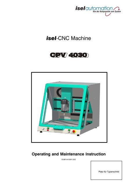
<strong>isel</strong>-<strong>CNC</strong> <strong>Machine</strong><br />
Operating and Maintenance Instruction<br />
B.2801xxV/2001.22/E<br />
Platz für Typenschild
<strong>isel</strong>-<strong>CNC</strong> <strong>Machine</strong> CPV<br />
On this Manual<br />
Various symbols are used in this Manual to quickly provide you with brief information.<br />
Danger Caution Note Example Additional<br />
Information<br />
© <strong>isel</strong>automation GmbH & Co.KG 1998<br />
All rights reserved.<br />
Despite all care, printing errors and mistakes cannot be ruled out completely.<br />
Suggestions for improvement and notes on errors are always welcomed.<br />
<strong>isel</strong> machines and controllers are CE compliant and are marked accordingly.<br />
Any other machine parts and components subject to the CE safety guidelines may not be<br />
commissioned unless all relevent standards are fulfilled.<br />
<strong>isel</strong>automation GmbH & Co.KG shall not accept any liability for any modifications on the device by the<br />
customer.<br />
The limit values specified in the Certificate of Conformity only apply to the original<br />
configuration from works.<br />
Manufacturer: Co. <strong>isel</strong>automation GmbH & Co. KG<br />
Bürgermeister-Ebert-Str. 40<br />
D-36124 Eichenzell<br />
Fax: +49-6659-981-776<br />
E-Mail: automation@<strong>isel</strong>.com<br />
http://www.<strong>isel</strong>.com<br />
2
<strong>isel</strong>-<strong>CNC</strong> <strong>Machine</strong> CPV<br />
The CPV is a compact machine with servomotors, which provides an abundance of<br />
possibilities for machining workpieces.<br />
The advantages in comparison with stepper motor control systems are:<br />
- higher traversing speeds<br />
- lower noise, no resonance effects<br />
- continuous-path control<br />
- exact positioning using position control with position encoder<br />
The machine is offered in different variants:<br />
- The standard variant incorporates the complete electronics including the isy-CAM and<br />
REMOTE software, as well as a main spindle drive.<br />
- The second variant incorporates the machine without electronics. That means that you can<br />
use your own control system.<br />
For the exact extent of delivery and the machine specification / accessories that come with<br />
the machine, please refer to your note of delivery.<br />
As a prerequisite for your work with the CPV, you will need basic knowledge in <strong>CNC</strong><br />
engineering and PC application, a computer, a mains socket, and some creativity.<br />
Please follow this brief instruction to be able to<br />
• properly install the equipment,<br />
• work in a safe, quick and effective manner,<br />
• keep away hazards from persons,<br />
• thus exploiting the full potential.<br />
We wish much success for your future work with the CPV.<br />
3
<strong>isel</strong>-<strong>CNC</strong> <strong>Machine</strong> CPV<br />
Contents<br />
1 Intended Purpose ............................................................................................................. .5<br />
2 Safety Notes ...................................................................................................................... .6<br />
3 Set-Up and Connection .................................................................................................... .8<br />
4 Start-Up .............................................................................................................................11<br />
4.1 Preliminary Remarks ............................................................................................................. .11<br />
4.1.1 Coordinate System ............................................................................................................... .11<br />
4.1.2 System Requirements ........................................................................................................... .11<br />
4.1.3 Push-Buttons and Switches ................................................................................................... .12<br />
4.2 Installing the Driver Software ................................................................................................. .13<br />
4.3 Starting the Software ............................................................................................................. .13<br />
4.4 Opening the Cover ................................................................................................................ .14<br />
5 Cleaning / Maintenance ....................................................................................................15<br />
6 Troubleshooting ...............................................................................................................17<br />
7 Technical Specifications / Accessories ............................................................................19<br />
7.1 Mechanics ............................................................................................................................. .19<br />
7.2 Electrical Components .......................................................................................................... .19<br />
7.3 Starting Up the UPMV 4/12 ................................................................................................... .28<br />
7.3.1 Base Address ........................................................................................................................ .28<br />
7.3.2 Interrupt Source of the Servomotor Control Card ................................................................. .28<br />
7.3.3 Signal I/O .............................................................................................................................. .29<br />
7.4 Evaluation of Limit and Reference Switches ......................................................................... .33<br />
7.4.1 Limit Switches ....................................................................................................................... .33<br />
7.4.2 Reference Switches ............................................................................................................... .33<br />
7.4.3 Enable ................................................................................................................................... .34<br />
7.4.4 Safety Shutdown ................................................................................................................... .34<br />
7.5 Connectors ........................................................................................................................... .35<br />
7.6 Charts and Tables .................................................................................................................. .37<br />
7.6.1 Block Diagram of Safety Circuit ............................................................................................ .37<br />
8 Accessories ......................................................................................................................38<br />
9 Appendix ...........................................................................................................................39<br />
Certificate of Conformity ...................................................................................................... .39<br />
10 Service waybill ................................................................................................................ .40<br />
4
<strong>isel</strong>-<strong>CNC</strong> <strong>Machine</strong> CPV<br />
1 Intended Purpose<br />
The CPV is a machine tool with three electronically controlled linear axes.<br />
Another (rotary) axis is offered as an option.<br />
- The machine is designed for training and small-series production.<br />
- It is designed for use in dry rooms, business rooms, living and training areas, as well as in<br />
laboratories and small firms (max. ambient temperature 40° C).<br />
- The machine is suitable for milling, boring, cutting, engraving, proportioning, measuring,<br />
positioning, and many similar applications.<br />
- You can mount a great variety of machining tools or measuring instruments according to<br />
the above mentioned applications.<br />
- Suitable materials are light metal, plastics, wood, glass and printed circuit materials.<br />
For safety reasons, graphite may not be used (explosion hazard).<br />
Any materials that produce hazardous gases when being processed may also not be<br />
used.<br />
- The machine is prepared for a suction apparatus. This suction apparatus is preferably<br />
intended for dry dust kinds (wood, printed circuit boards etc.).<br />
- The complete control and power electronics of three axes is housed in the machine. The<br />
control system is installed in the standard machine. Only the UPMV 4/12 and the multi I/O<br />
cards are housed in the control computer.<br />
- A fourth axis can easily be integrated to upgrade the control system.<br />
- You can control the machine from almost any IBM compatible computer. The only<br />
prerequisite is that it must have at least three free ISA slots (one for the servomotor power<br />
card UPMV 4/12 and two for the two multi I/O cards).<br />
- Eight 24 V outputs and sixteen 24 V inputs are available as an option to connect further<br />
components.<br />
- With the isy-CAD/CAM software, you can directly pass on the previously generated<br />
<strong>CNC</strong> data to the machine, thus initiating the workpiece to be machined using an<br />
appropriate control program (REMOTE).<br />
5
<strong>isel</strong>-<strong>CNC</strong> <strong>Machine</strong> CPV<br />
2 Safety Notes<br />
- Do not operate the machine in potentially explosive atmospheres.<br />
- The machine is completely encapsulated. The casing protects you against moving tools,<br />
decreases the operating noise level and restrains the chips.<br />
- On machining, the cover is locked and cannot be opened.<br />
You may neither remove nor modify this protection measure.<br />
- For emergency situations, you find an Emergency Stop switch on the front-panel of the<br />
machine.<br />
It interrupts the power supply to the power outputs and to the converter of the main<br />
spindle drive. The converter therefore no longer provides a brake voltage, and the spindle<br />
motor slowly runs down.<br />
- The system should not often be restarted/shut down. Wait at least 60 seconds before you<br />
turn on the system again.<br />
- Only experts and trained persons may handle the key-operated switch because of<br />
increased hazards in test mode.<br />
Please, keep the spare key under lock and key.<br />
- Provide sufficient ventilation at dust or gas development caused by the machining of the<br />
materials.<br />
- If you want to use a laser for measuring applications, use only suitable devices (laser class<br />
2) and observe the relevant technical regulations and safety instructions.<br />
- For cooling, no flowing water may be used but only a sprinkling/chilling appliance with<br />
which a spray causes the cooling effect (see Accessories).<br />
Make sure that no drops form and flow under the clamping plate.<br />
- Do not use spirit as a coolant (explosion hazard).<br />
- Clean the machine at regular intervals and remove chips and dust deposits. Do not use<br />
aggressive cleaning agents or solvents that may damage the paint or the plastic washers.<br />
6
<strong>isel</strong>-<strong>CNC</strong> <strong>Machine</strong> CPV<br />
Aging of Safety Panes<br />
Investigations, accomplished by the Association of German <strong>Machine</strong> Tool Factories (VDW)<br />
in connection with the responsible employer's liability insurance association have pointed<br />
out new aspects about the aging of polycarbonate as material for safety panes at<br />
machine tools. Although polycarbonate worked very good for this purpose, these panes<br />
sometimes substantially lose their ability to hold back flying around parts, especially<br />
under the influence of cooling lubricants. At longer term, polycarbonate panes that are<br />
double-sided protected against the effects of splinters, cooling lubricants, detergents,<br />
steams, etc. have hereby shown the highest resistance.<br />
In order to set you in the position to carry out your care business, we would like to<br />
point out that safety panes made of polycarbonate are therefore to be examined<br />
regularly for their retaining abilities and to be changed if necessary. Additionally, such<br />
safety panes are to be classified as wearing parts in future. Beyond that, when you sale<br />
it, you are also obligated to inform the possible buyer of such a machine accordingly<br />
about that.<br />
Even with consideration of these new realizations polycarbonate will be further used as<br />
material for safety panes in mechanical engineering due to its extremely high retaining<br />
ability. Spare panes ready to be installed can therefore be ordered from us at any time.<br />
In order to increase the necessary exchange intervals, we can also offer a retrofit kit for<br />
an additional protection on the operator side if desired.<br />
7
<strong>isel</strong>-<strong>CNC</strong> <strong>Machine</strong> CPV<br />
3 Set-Up and Connection<br />
The machine comes completely mounted on a palette.<br />
The extent of delivery of the standard CPV contains:<br />
• <strong>Machine</strong> housing with three linear axes<br />
- complete control electronics for three axes<br />
- main spindle drive (500 W)<br />
• Mounting set (hand lever, stop bars, 5 mm socket spanner)<br />
• Triangular wrench for unlocking the cover switch<br />
• Mains supply cable<br />
• Driver software for DOS including set-up program “<strong>isel</strong>drv”, 1 diskette, 1 manual<br />
• Software either:<br />
REMOTE program, 1 diskette + machining example<br />
CAD/CAM software isy-CAM, 1 CD, 1 manual<br />
or:<br />
PRO-PAL program, 1 floppy disk, 1 manual<br />
• and these Operating and Maintenance Instructions<br />
The servo motor control card UPMV 4/12s, both Multi I/O cards and the connection cables<br />
are included in the extent of delivery of the control computer, which you have ordered at the<br />
same time.<br />
The space requirements of the machine is limited to the external dimensions and to sufficient<br />
space in front of the machine to be able to operate and set up the machine.<br />
Leave approx. 10 cm at the rear side for the plugs and connectors. The cover of the housing<br />
opens upwards so that the required total height is approx. 1.2 meters.<br />
ca. 1200 mm<br />
CPV 4030<br />
710 mm<br />
ca. 1320 mm<br />
Dimensions and space requirements<br />
Remove the sheet steels from the feet of the machine, with which it is secured on the palette.<br />
Then, set the machine horizontally on an even, solid surface.<br />
Use the adjustable rubber feet of the machine to adjust uneven patches of the floor.<br />
8
<strong>isel</strong>-<strong>CNC</strong> <strong>Machine</strong> CPV<br />
During transportation, please pay attention to the supply and connection cables (remove<br />
them if necessary) so that they are not damaged. Use only suitable lifting devices.<br />
In particular, when transporting the machine always keep the triangular wrench outside<br />
the machine.<br />
The mounting set consists of a<br />
hand lever clamping assembly and<br />
two stop bars with mounting<br />
hardware for the T-slot plate.<br />
2 x<br />
Always ensure that the<br />
workpieces are properly secured.<br />
For the accessories, different parts are already pre-installed or prepared for mounting.<br />
Refer also to the information provided in the Appendix.<br />
Mount the rotary axis (option) on the T-slot plate as prescribed in the Rotary Axis Mounting<br />
and Operating Instructions. Connect the cable to the rotary axis and to the connector in the<br />
rear panel of the work space.<br />
For the selection of the rotary axis, refer to the UPMV 4/12 Operating Instructions.<br />
The main spindle motor is directly wired and<br />
software-controlled. Various tools with a shaft<br />
diameter of max. 6.35 mm (other diameters see<br />
Accessories) can be mounted in the collet chuck of<br />
the main spindle motor. To change the collet chuck,<br />
use the provided tools (SW 15 open end wrench and<br />
a hook spanner).<br />
Appropriate holders are provided to attach also<br />
other tools, measuring instruments (laser) or other<br />
suitable facilities on the T-slot plate of the Z axis.<br />
Make sure that these tools are exactly aligned<br />
parallel to the XY plane.<br />
9
<strong>isel</strong>-<strong>CNC</strong> <strong>Machine</strong> CPV<br />
Connecting Lines<br />
To link the machine with your computer, please use the provided cables (for servomotor<br />
control card UPMV 4, multi I/O cards and/or motor cables, diverse control cables). For the<br />
pin assignment of the Sub-D connectors of the CPV without electronics, refer to the Technical<br />
Specifications in Section 7.5.<br />
Connection panel of the CPV with integrated electronics<br />
➀ Connection of confirmation key (9-pin Sub D connector)<br />
➁ UPMV 4/12 (50-pin ribbon connector)<br />
➂ Multi I/O for safety circuit SK (37-pin Sub D connector)<br />
➃ Multi I/O for user I/O (37-pin Sub D connector)<br />
➄ Earthing point<br />
➅ Main switch<br />
➆ Mains connection<br />
➇ Fuse (10 A, slow-blow)<br />
Connection panel of the CPV without electronics<br />
➀ Z axis<br />
(Amphenol connector, C16-3))<br />
➁ X axis<br />
(Amphenol connector, C16-3)<br />
➂ Y axis<br />
(Amphenol connector, C16-3)<br />
➃ A axis (rotary axis)<br />
(Amphenol connector, C16-3)<br />
➄ START and STOP keys<br />
(9-pin Sub D connector)<br />
➅ Cover switch<br />
(9-pin Sub D connector)<br />
➆ POWER / emergency stop button (15-pin Sub D connector)<br />
➇ Earthing point<br />
➈ Input of machine tool<br />
10
<strong>isel</strong>-<strong>CNC</strong> <strong>Machine</strong> CPV<br />
4 Start-Up<br />
4.1 Preliminary Remarks<br />
4.1.1 Coordinate System<br />
- The coordinate system of the<br />
machine is defined as shown in<br />
the illustration whereby you<br />
can freely select (move) the<br />
workpiece zero point P0 via<br />
software.<br />
P 0<br />
- Labels on the machine mark the<br />
axes.<br />
- The arrangement of the axis<br />
positions is free; refer to the ISELDRV Driver Manual.<br />
Reference point and home position<br />
By default, the reference point of the machine (machine<br />
zero point) and the home position are preset to the rear<br />
corner (Y), left (X) and top (Z).<br />
The reference point is set by hardware limit switches; the<br />
home position of the control system is transferred to the<br />
control system via an electromagnetic switching contact.<br />
The solenoid as the pulse generator is mounted to the<br />
housing, and the reading contact on the Z axis senses<br />
the home position if it receives the pulse from the solenoid.<br />
4.1.2 System Requirements<br />
To control the <strong>CNC</strong> machine, you will need an IBM compatible computer with free slots for<br />
the servo motor control card UPMV 4/12 and two multi I/O cards.<br />
System requirements<br />
- 486 SX, 40 MHz or higher<br />
- 8 MB RAM<br />
- 20 MB of free hard disk capacity<br />
- VGA card<br />
- MS-DOS 5.0 or higher<br />
- three free ISA slots<br />
If you use an <strong>isel</strong>-controller, it is fit to the machine and ready for start-up.<br />
11
<strong>isel</strong>-<strong>CNC</strong> <strong>Machine</strong> CPV<br />
4.1.3 Push-Buttons and Switches<br />
The black main switch is located on the rear side of the machine directly beside the mains<br />
connection.<br />
Using the switches and/or push-buttons on the front side, you can switch on/off the<br />
machine and start or stop the machining process.<br />
➀ Emergency Stop<br />
Use this button to interrupt the power supply to the<br />
motor power output stages and to the spindle<br />
motor.<br />
The cover can be opened using the ➅ push-button.<br />
The Emergency Stop button is unlocked by turning to<br />
the right.<br />
6 5 4 3 2<br />
1<br />
➁ POWER<br />
Use this key to turn on the power output stages<br />
You can only turn on the power stages if the Emergency Stop button is unlocked and the<br />
cover is closed.<br />
➂ Key-operated switch<br />
Use this key to switch between test and automatic operation.<br />
AUTO = machining mode<br />
Use STOP to interrupt machining and START to continue.<br />
TEST = test mode<br />
In this operating mode, you can open the cover at any time. As long as you hold<br />
down the START key, all machine functions remain stored.<br />
Releasing the ACKNOW key with the cover opened will result in Emergency Stop<br />
and shutdown of the power supply.<br />
Pay attention to the moving carriage: Hazard of personal injury!<br />
➃ START<br />
Use this button to start machining or restart the movement after stop ➄ exactly from the<br />
position at which the movement has been interrupted if the machining has not been<br />
completed from the user interface.<br />
Can be used in test mode to traverse the carriages with the cover open.<br />
➄ STOP<br />
Use this key to stop the current program immediately and to hold the program at the<br />
break point. Use the START key to continue the program with the cover closed.<br />
➅ COVER<br />
Use this key to unlock the cover switch.<br />
Only if the COVER key lights, you can open the cover by pressing this key (first, press<br />
the key, then simultaneously pull the grip!).<br />
Do not reach into the tool that may run down.<br />
12
<strong>isel</strong>-<strong>CNC</strong> <strong>Machine</strong> CPV<br />
4.2 Installing the Driver Software<br />
Install the software according to the UPMV 4/12 Operating Instructions (pages I - VI).<br />
install.bat<br />
The directory with the files is already installed on every <strong>isel</strong> control computer on delivery.<br />
Among other files, the following files are on the installation diskettes:<br />
- servo.ini contains the set operating parameters and INSTALL files<br />
required for the UPMV 4/12 card<br />
- propal.ini setting values for PRO-PAL (preset) (optional)<br />
- remote.ini setting values for REMOTE (optional)<br />
- drv.bat required for starting the <strong>isel</strong>drv.exe driver<br />
- cover.exe required to open the cover without having installed the driver<br />
4.3 Starting the Software<br />
Make sure that the machine is correctly linked with the other components (control<br />
computer, plug-in cards) (as per Chapter 3).<br />
If the control computer is contained in the extent of delivery:<br />
1. Turn on the control computer and the machine.<br />
2. In the control computer, go to the subdirectory “servo”.<br />
cd servo<br />
3. Call the batch file “drv.bat” to start the software.<br />
drv<br />
4. Start the machining program.<br />
You can chose from the following programs (depending on your order):<br />
- REMOTE ® re.bat<br />
- PRO-PAL (portal equipment) ® ppp.bat<br />
- PRO-DIN (portal equipment) ® pdp.bat<br />
You must install the isy-CAD/CAM software by yourself.<br />
No batch file is prepared.<br />
If you intend to use your own control computer:<br />
When have installed the UPMV 4/12 and the two multi-I/O cards, first install the provided<br />
driver software. (Please proceed as per description of the UPMV 4/12 servomotor control<br />
card, p. I - VI, see also Section 7.3)<br />
Carry out all further steps as described above (Items 2 - 4).<br />
13
<strong>isel</strong>-<strong>CNC</strong> <strong>Machine</strong> CPV<br />
4.4 Opening the Cover<br />
During commissioning, carry out the following steps:<br />
- To open the cover, connect the mains cable and turn on the mains switch (on the rear side).<br />
Make sure that the control computer is ready for operation.<br />
Either start the operating software or the cover.exe file from the installation diskette<br />
ISELDRV V3.2. Set the key-operated switch to TEST mode. The COVER key ➅ should now<br />
light; open the cover only if this key lights.<br />
To enable the following functions, make sure that the EMERGENCY STOP button is<br />
unlocked. Return to AUTOMATIC mode.<br />
- Close the cover and press the POWER key ➁ to turn on the output stage; the push-button<br />
must light.<br />
- The spindle motor can be turned on in AUTOMATIC mode only if the POWER key lights,<br />
the cover is closed and locked and if the software communicates with the machine.<br />
- During the machining, the cover is locked. You can only open the cover if the machine has<br />
been stopped, the spindle motor is switched off, the machine is in home position and the<br />
software allows the cover to be opened (COVER key lights).<br />
- To open the cover, push the COVER key. If the cover has been closed, it will be locked<br />
automatically. To start the machine, push the START key again.<br />
Key-operated switch<br />
To test the program, you can nevertheless open the cover during operation if you turn the<br />
key-operated switch to TEST.<br />
The working program stops the drive axes immediately and goes on running if you hold<br />
down the START key.<br />
This key may only be used by expert and authorised personnel since after opening the<br />
cover no more protection against moving machine parts is provided.<br />
14
<strong>isel</strong>-<strong>CNC</strong> <strong>Machine</strong> CPV<br />
5 Cleaning / Maintenance<br />
Open the cover before switching off the machine. Then, it is no more possible.<br />
Before you start any cleaning or maintenance work, trip the main switch and remove the<br />
mains plug to avoid the system from being restarted.<br />
Remove all chips from the machine at regular intervals using a broom or vacuum cleaner<br />
(no compressed air). This protects the mechanics against early wear.<br />
- With frequent machining operations and very fine chips (dusts), you should regularly<br />
remove the cover plate of the Y axis below the T-slot plate and remove possibly penetrated<br />
chips and/or dusts.<br />
- The sealing lips include a Teflon component and require no special maintenance.<br />
- Clean the Perspex windows with a non-abrasive fluid cleaner.<br />
- The shaft guides and drive shafts come with long-term lubrication. Depending on the load,<br />
you should grease the shaft guides and drive shafts approx. every 500 ... 1,000 operating<br />
hours. Use standard roller bearing grease.<br />
The shaft guides and shafts come lubricated with GP00/000F-20 sodium soap grease to<br />
DIN 51 502.<br />
If you use oil, lubricate every 100 ... 200 operating hours.<br />
To lubricate the drive axes, first do a reference approach, then open the cover and only<br />
now switch off the machine.<br />
15
<strong>isel</strong>-<strong>CNC</strong> <strong>Machine</strong> CPV<br />
To lubricate the Y axis, move* the T-slot<br />
plate completely to the back and then<br />
remove from the Y axis (six screws).<br />
Remove the plastic plug beneath and<br />
lubricate through the lubricating nipple,<br />
which now becomes visible.<br />
Access to the guide rails is provided<br />
through the sealing lips.<br />
S<br />
To remove the cover sheet of the Y axis,<br />
loosen all fastening screws.<br />
S marks the access to the lubricating points in all drawings.<br />
To lubricate the X axis, move the<br />
carriage to the left*, remove the<br />
plastic plug on the left-hand side of<br />
the machine and lubricate through<br />
the lubricating nipple, which now<br />
becomes visible.<br />
Access to the guides rails is provided<br />
through the sealing lips.<br />
S<br />
First, remove the spindle motor from the Z axis, remove<br />
the three plugs and push the carriage completely down*.<br />
Apply some oil to the guide rails through the two side<br />
holes.<br />
The lubricating nipple for the drive is now behind the front<br />
opening.<br />
* If the machine is switched off you can<br />
move the carriage manually.<br />
16
<strong>isel</strong>-<strong>CNC</strong> <strong>Machine</strong> CPV<br />
6 Troubleshooting<br />
Fault Cause Remedy<br />
Equipment cannot be turned on No mains power Check mains fuse,<br />
Check mains connection<br />
Mains switch not turned on<br />
Fuse defective (mains supply)<br />
Turn on mains switch<br />
Pull mains plug<br />
Replace fuse (see below)<br />
POWER key does not function Cover not closed Close cover<br />
Emergency Stop not unlocked<br />
Fuse defective (mains supply)<br />
Hardware limit switch activated<br />
Driver not loaded<br />
Unlock Emergency Stop<br />
Pull mains plug<br />
Replace fuse (see below)<br />
Go to home position<br />
install driver<br />
Software does not work correctly Equipment not turned on Turn on equipment (main switch)<br />
Output stage not turned on<br />
Driver not loaded<br />
Connection not correct<br />
Turn on output stage (POWER key)<br />
Install driver<br />
Check cable connections<br />
Spindle motor does not work Not enabled by software System reset and go to home position<br />
Adjustments in the software<br />
not correct<br />
Check spindle settings<br />
Scaling of axes Leadscrew pitch does not corres- Change the leadscrew pitch in the<br />
not correct pond to the setting in the software driver program to 4 or 10 mm<br />
Output stage does not function Fuse defective (power block) Pull the mains plug<br />
Replace fuse (see below)<br />
17
<strong>isel</strong>-<strong>CNC</strong> <strong>Machine</strong> CPV<br />
Replacing the Fuses<br />
Pull the mains plug before changing any fuse!<br />
Access to the main fuses of the machine ➅ is provided from the outside. They are located<br />
directly beside the mains plug.<br />
To replace the other fuses,<br />
remove the rear panel. There you<br />
find:<br />
will<br />
➀<br />
➁<br />
➂<br />
➃<br />
➄<br />
➅<br />
➆<br />
Power output stages<br />
Power block<br />
Terminal board<br />
Frequency converter<br />
Terminal block<br />
Mains input with main switch<br />
SK module<br />
Positions of the fuses ...<br />
... at mains input ➅ ... in the SK module ➆ ... in the power block ➁<br />
2 x 10 A, HBD slow-blow 2.5 V/ 250 V 4 x 10 A/80 V<br />
Triangular wrench<br />
For special cases (if a switch is defective or in case of power failure etc.), you can open the<br />
cover interlock manually using the triangular wrench.<br />
1. Switch off the machine and lift the machine.<br />
2. Remove the four screws and the shield in the bottom plate.<br />
3. Insert the triangular wrench into the interlock<br />
from below and turn it around half a turn to the<br />
left without applying excessive force.<br />
Do not operate the<br />
machine in this state.<br />
Hole to the keyswitch (from below)<br />
18
<strong>isel</strong>-<strong>CNC</strong> <strong>Machine</strong> CPV<br />
7 Technical Specifications / Accessories<br />
7.1 Mechanics<br />
CPV 4030<br />
Dimensions w x d x h [mm] 710 x 820 x 750<br />
Traversing ranges X axis [mm] 395<br />
Y axis [mm] 300<br />
Z axis [mm] 110<br />
Passing height [mm] 150<br />
Clamping table [mm] 375 x 600<br />
T-slot raster [mm] 25<br />
Approx. weight [kg] 95<br />
Sound pressure level<br />
< 75 decibel (A)<br />
Mains rating<br />
230 V, 50 Hz, 16 Amp<br />
Driving motor<br />
120 W each<br />
Main spindle motor<br />
500 W<br />
Fusing<br />
power input 2 x 10 Amps, slow-blow HBD<br />
Earthing corresponds to protection class I.<br />
EMC test to EN 55011-B and EN 50082-1<br />
Subject to changes without prior notice<br />
7.2 Electrical Components<br />
The main electrical components are:<br />
- Power block PB 600-R<br />
- Servomotor power output stage PVM 0810<br />
- Safety circuit module SVM-1<br />
- Terminal block BIG 1608<br />
- Frequency converter<br />
- Control computer (external, not included in the standard extent of delivery)<br />
- Servomotor control card UPMV 4/12<br />
- Two multi I/O cards<br />
The complete system (machine and control computer) complies with<br />
EN 50081-1 and EN 50082-2 EMV.<br />
19
<strong>isel</strong>-<strong>CNC</strong> <strong>Machine</strong> CPV<br />
PB 600-R Power Block<br />
• 600 VA toroidal-core transformer with temperature control<br />
• Electronic starting current limiting<br />
• Overvoltage protection of motor output voltage<br />
• Auxiliary voltage I + 24 V/2 A<br />
• Auxiliary voltage II + 24 V/1 A (safety circuit)<br />
• Closed sheet steel housing L x W x H: 220 x 150 x 140 mm<br />
• Contacting via connectors<br />
The PB 600-R power block is a compact power supply unit for power output stages/<br />
controllers. The power block provides both an non-stabilised intermediate-circuit voltage<br />
as an operating voltage for the power output stages and a + 24 V stabilised voltage for<br />
the supply of limit switches and sensors.<br />
Another + 24 V power circuit is provided in the power block to perform control and<br />
monitoring functions of safety-relevant components and to carry out emergency stop<br />
cut-out of the motor voltage.<br />
The PB 600-x power block is type-tested and is subject to a production control by the<br />
VDE (VDE Test Certificate 6224).<br />
PB 600-R power block<br />
20
<strong>isel</strong>-<strong>CNC</strong> <strong>Machine</strong> CPV<br />
PVM 0810 Power Output Stage<br />
• 3 or 4 UMV 10 servomotor power boards<br />
• Set-value specification: ± 10 V (current control)<br />
• Evaluation of encoder signals to RS 422<br />
• Protective circuits for overvoltage, overcurrent, overtemperature<br />
• Front-panel displays for operation, fault and output stage shutdown<br />
• Control input via 50-pin ribbon plug connector<br />
(compatible with the UPMV 4/12 servomotor card)<br />
• Supply voltage input and motor output via board plug connector<br />
• Monitoring of 8 limit switches in the drive axes<br />
• Signal input for function monitoring of the servomotor control card<br />
(readiness for operation of the control computer, watchdog)<br />
PVM 0810 Servomotor power output stage<br />
21
<strong>isel</strong>-<strong>CNC</strong> <strong>Machine</strong> CPV<br />
SVM-1 Safety Circuit Module<br />
• Two operating states that can be selected using a key-operated switch<br />
- AUTOMATIC mode<br />
- Test mode<br />
• Control of the cover function<br />
• Enabling of main spindle drive<br />
• External operating console with the following function keys:<br />
- EMERGENCY STOP<br />
- POWER key (power output stage ON)<br />
- Key-operated switch (mode selector switch)<br />
- ACKNOW key (confirmation key)<br />
- START key (program start)<br />
- STOP key (program stop)<br />
- COVER key (cover control)<br />
• Display of the operating states by a 10-digit LED display<br />
• + 24 V power supply (external)<br />
The safety circuit module monitors the safety-relevant components of the controller and<br />
extends the operating facilities of the machine by mode selector switches and control<br />
keys.<br />
SVM-1 safety circuit module<br />
The function of the safety circuit module is only ensured if all control and operating units are<br />
connected (safety switch etc.).<br />
22
<strong>isel</strong>-<strong>CNC</strong> <strong>Machine</strong> CPV<br />
BIG 1608 Terminal Board<br />
• Signal and terminal-compatible with the <strong>isel</strong> multi I/O card<br />
• Status display of the inputs/outputs by LEDs<br />
• Connection of the inputs/outputs via modular terminal blocks<br />
• Analog output for speed control of a main spindle drive<br />
• Power supply by integrated primary switched-mode power supply (60 VA)<br />
The terminal board serves as an adaptation aid to the 37-pin Sub D connector of the multi<br />
I/O card.<br />
The signal inputs and outputs of the multi I/O cards are provided to the corresponding<br />
connector X1 of the terminal board using a 1:1 connection line and connected there to a<br />
user-friendly screw-type terminal connector.<br />
At the same time, the module possesses LED displays to display the state of the inputs<br />
and outputs.<br />
For power supply, the module requires a +24 V d.c. voltage.<br />
This is provided by an integrated primary switched-mode power supply (60 VA).<br />
other<br />
specifications<br />
outputs<br />
inputs<br />
inputs<br />
60 VApower<br />
supply<br />
connection<br />
multi I/O card<br />
BIG 1608 terminal board<br />
23
<strong>isel</strong>-<strong>CNC</strong> <strong>Machine</strong> CPV<br />
Frequency Converter for Main Spindle Drive<br />
The main spindle drive consists of the following components:<br />
- spindle motor and<br />
- frequency converter.<br />
The spindle motor is a two-pole asynchronous motor with an output of 500 W (S6-40 %<br />
operation). Controlled by a frequency converter, the motor is designed for a max. speed of<br />
24,000 rpm.<br />
For tool mounting, collet chucks ranging from 3 mm to 6.35 mm (1/4”) are provided (see<br />
“Accessories”).<br />
The motor is controlled by a 1,100 VA frequency converter integrated in the CPV.<br />
To control speed and direction of rotation, the signal inputs of the converter are wired with<br />
the terminal board and the SK module of the machine. This ensures that apart from the<br />
speed setting (by the analog output of the connected multi I/O card), the handling of the<br />
EMERGENCY STOP situation is also provided.<br />
The power supply of the converter (AC 230 V) is provided via the mains input plug of the<br />
CPV.<br />
Converter for the main spindle drive<br />
24
<strong>isel</strong>-<strong>CNC</strong> <strong>Machine</strong> CPV<br />
Control Computer<br />
Housing<br />
• solid sheet steel system rack for PC components<br />
• 19" drawout-unit design (4 HE)<br />
• alternatively: powder-coated aluminium half-shell housing<br />
(anthracite), dimensions W x H x T: 475 x 186 x 410 mm<br />
Configuration • Processor Pentium (min. 200 MHz)<br />
• RAM<br />
• Hard disk (optional)<br />
16 MB<br />
min. 2.1 GB<br />
• Graphics card PCI, (4 MB )<br />
• Floppy drive<br />
• CD ROM drive<br />
• Ports<br />
• Power supply<br />
3.5"/1.44 MB<br />
24-fold<br />
2 serial, 1 parallel<br />
200 W (TÜV)<br />
The control computer is configured using the components available at the date of delivery.<br />
The features listed above are the minimum system requirements.<br />
Opened control computer (desk-top housing)<br />
a) UPMV 4/12 servomotor control card<br />
b) Two multi I/O cards<br />
The <strong>isel</strong> control computer (not included in the standard extent of delivery) currently consists of<br />
a compact Pentium computer with hard disk, floppy drive and PCI graphics card. The solid<br />
sheet steel housing provides high operational reliability of the system and ensures the<br />
compliance with the existing EMC regulations (noise emission, noise immunity).<br />
25
<strong>isel</strong>-<strong>CNC</strong> <strong>Machine</strong> CPV<br />
Multi I/O Card (2x)<br />
• PC plug-in card (l = 250 mm) for ISA slot<br />
• 16 opto-isolated signal inputs (+ 24 V, industry standard)<br />
• 8 relay outputs (+ 24 V switching, 300 mA)<br />
• Opto-isolated analog output (± 10 V)<br />
• Card output via 37-pin Sub D connector<br />
The multi I/O card with 16 inputs and 8 outputs (as a PC plug-in card) is tailored to the<br />
needs of binary-data acquisition and exchange.<br />
The PC card is 250 mm long and can be inserted into any PC or industrial computer<br />
using a 16-bit ISA bus connector.<br />
The settable basic address provides both a combination with other PC plug-in cards and<br />
a cascading of several multi I/O cards.<br />
Multi I/O card<br />
For more information, refer to the Readme file contained in the provided software.<br />
26
<strong>isel</strong>-<strong>CNC</strong> <strong>Machine</strong> CPV<br />
UPMV 4/12 Servomotor Control Card<br />
• 4 independent axis processors<br />
• 32-bit set-value registers, acceleration registers<br />
• 32-bit position measurement<br />
• Programmable 16-Bit PID controller, sampling interval 0.35 ms<br />
• 12-bit D/A output (± 10 V speed set value)<br />
• 8 signal inputs for limit switches (opto-isolated)<br />
• 4 signal inputs for reference/zero-point switches (opto-isolated)<br />
• Signal input Output Stage Fault (opto-isolated)<br />
• Signal input Enable Limit Switch (opto-isolated)<br />
• Signal output Output Stage Shutdown (opto-isolated)<br />
• Signal output Enable Limit Switch (opto-isolated)<br />
• Connection via 50-pin ribbon connector<br />
The UPMV 4/12 servomotor control card is a PC plug-in card (approx. 380 mm long) for the<br />
selection of up to four d.c. servomotors.<br />
- It integrates four independent, digital axis processors, type National LM628.<br />
- Apart from the function blocks of the PID position control of the d.c. servomotors and setvalue<br />
generation, the processors also include the position measurement of the numerical<br />
axes by evaluating the pulse sequences using the incremental rotary encoder flanged on<br />
the motor.<br />
To suppress any line-borne interference, the signals on the rotary encoder side are<br />
converted to RS422 using symmetric signal drivers.<br />
The control card as an output to the external power output stage provides a speed set<br />
value of<br />
± 10 V. A monitoring of the limit and reference switches in the servosystem is by evaluating<br />
opto-isolated + 24 V signal outputs.<br />
- In addition, the card has an input for fault messages of the output stage and outputs to<br />
short-circuit the limit switches, to switch off the power output stages and for safety<br />
shutdown of the PC card.<br />
- To install the card, a 16-bit ISA slot is required in the control computer.<br />
UPMV 4/12 servomotor control card<br />
27
<strong>isel</strong>-<strong>CNC</strong> <strong>Machine</strong> CPV<br />
7.3 Starting Up the UPMV 4/12<br />
7.3.1 Base Address<br />
The communication of CPU and PC plug-in cards is carried out by data exchange within a<br />
defined address window of the adopted AT bus. This requires the active address range on the<br />
corresponding PC plug-in card to be set accordingly.<br />
To this aim, various address spaces are predefined for the appropriate application cards.<br />
For user applications, normally the address range from 300h to 36Fh is provided.<br />
X1 - output connector<br />
J1 - base address jumper section<br />
J2 - interrupt jumper section<br />
The setting of the active address range on the UPMV 4/12 is carried out using the coding<br />
section J1. The following assignment is applicable:<br />
J1.1 J1.2 J1.3 J1.4 J1.5 J1.6 Base address<br />
(A9) (A8) (A7) (A6) (A5) (A4) set<br />
OFF OFF ON ON ON ON 300h - 31Fh<br />
OFF OFF ON ON ON OFF 310h - 31Fh<br />
OFF OFF ON ON OFF ON 320h - 32Fh<br />
OFF OFF ON ON OFF OFF 330h - 33Fh<br />
OFF OFF ON OFF ON ON 340h - 34Fh<br />
OFF OFF ON OFF ON OFF 350h - 35Fh<br />
OFF OFF ON OFF OFF ON 360h - 36Fh<br />
ON = Jumper plugged OFF = Jumper open Standard setting<br />
Please make sure that address ranges of different PC plug-in cards do not clash.<br />
7.3.2 Interrupt Source of the Servomotor Control Card<br />
Hardware Interrupt<br />
The driver software (motion module) to the servomotor control card requires a defined<br />
hardware interrupt during interpolation mode.<br />
To avoid double assignment of different PC cards, the UPMV 4/12 provides the choice from<br />
two interrupt sources. To this aim, activate one interrupt source and plug jumper J2 as<br />
indicated in the Table below.<br />
J2.1 IRQ10<br />
J2.2 IRQ11 (standard setting)<br />
J2.3 IRQ12 (cannot be used)<br />
J2.4 IRQ13 (cannot be used)<br />
28
<strong>isel</strong>-<strong>CNC</strong> <strong>Machine</strong> CPV<br />
Software Interrupt<br />
The interrupt address 78h is used as the software interrupt (described in the start-up program<br />
more in detail).<br />
For more detailed information on the base address settings, refer to the Manual of the<br />
UPMV 4/12 servomotor control card (p. 12ff).<br />
7.3.3 Signal I/O<br />
In conjunction with a PVM 0810 power output stage, the inputs/outputs provide various<br />
functions. In the UPMV 4/12 servomotor control card, the inputs are controlled and<br />
monitored from two input ports and one output port.<br />
Input port 1: (address 30Ch)<br />
Bit 7 Bit 6 Bit 5 Bit 4 Bit 3 Bit 2 Bit 1 Bit 0<br />
Reference switch<br />
Fault Axis 4 Axis 3 Axis 2 Axis 1<br />
Output stage<br />
Input port 2: (address 30Eh)<br />
Bit 7 Bit 6 Bit 5 Bit 4 Bit 3 Bit 2 Bit 1 Bit 0<br />
Limit switch 1 Limit switch 2<br />
Axis 4 Axis 3 Axis 2 Axis 1 Axis 4 Axis 3 Axis 2 Axis 1<br />
The port addresses specified are correct provided you use the control card with the base<br />
address 300h.<br />
If you have set a different base address, you must make appropriate adaptations.<br />
The individual signals are:<br />
- Signal input of limit switch<br />
To ensure the maximum traversing travels and thus to provide protection of the connected<br />
axes, limit switches are used in the servosystems for the end positions of the axes.<br />
If one of these switches is actuated during operation, the monitoring circuit will switch off<br />
the power supply of the power output stages. At the same time, this operating state is<br />
transmitted to the servomotor control card in the control computer. Evaluation by software<br />
is possible by reading the input port 2 (base address + 0Eh).<br />
29
<strong>isel</strong>-<strong>CNC</strong> <strong>Machine</strong> CPV<br />
1N4148<br />
2k2<br />
X1.xx<br />
Limit switch<br />
(+ 24 V switching)<br />
X1.18<br />
GND<br />
Signal input of limit switch<br />
Programming example: Reading of signal input<br />
Base address<br />
300h<br />
Address of input port 2<br />
30Eh<br />
Input statements in Borland C inportb(0x30E)<br />
If the limit switch is properly installed and operates correctly, the data bits are 0. An<br />
activating or not connected switch will set the corresponding data bit to 1.<br />
- Reference switch signal input<br />
The numerical axes can be traversed to their zero or reference point by evaluating the<br />
reference point signal inputs. When approaching the reference point, all positioning<br />
commands will refer to this machine zero point in absolute dimensions or to a zero point<br />
later defined via software.<br />
2k2<br />
X1.xx<br />
Reference switch<br />
(+ 24 V switching)<br />
1N4148<br />
X1.18<br />
GND<br />
Reference switch signal input<br />
Programming example: Reading of signal input<br />
Base address<br />
300h<br />
Address of input port 1<br />
30Ch<br />
Input statement in Borland C inportb(0x30C)<br />
If the reference switch is installed correctly, the data bits will indicate the values 1 to 4; an<br />
activated or not connected switch will set the corresponding data bit to 1.<br />
30
<strong>isel</strong>-<strong>CNC</strong> <strong>Machine</strong> CPV<br />
- Fault at output stages (pin 19)<br />
In case of a malfunction, the power output stages UVE 8012 will generate an error signal,<br />
which is signalled by the opto-coupler output Output Stage Fault.<br />
This fault message is acquired in the servomotor power output stage together with the<br />
faults to follow and are transmitted to the UPMV 4/12 control card.<br />
The following signals/voltages are monitored as possible error sources:<br />
- Output stages switched off by software<br />
(signal output Output Stage Shutdown of UPMV 4/12 set)<br />
- Shutdown of one power output stage by overtemperature<br />
- Shutdown of one or several output stages by an overcurrent fault of the output stage<br />
transistors<br />
- Missing supply voltage (operating voltage + 70 V) not turned on)<br />
- Missing or defective/interrupted connecting line from the servomotor power output<br />
stage to the servomotor control card in the control computer<br />
The error message can be evaluated by the software by reading the address (base address<br />
+ 0Ch, bit 4).<br />
- Safety shutdown (pin 40)<br />
To ensure that the safety shutdown of the power electronics operates if the computer<br />
“bombs”, after the control computer has been switched off or in case of a run-time error,<br />
the UPMV 4/12 has a so-called watchdog monitoring.<br />
The respective output (pin 40 of the 50-pin ribbon connector) is active (+ 24 V), as long as<br />
the readiness for operation is ensured. The output is open in case of a fault at the control<br />
unit.<br />
- Output stage shutdown (pin 16)<br />
For start-up or control and measuring purposes, it can be reasonable to make the output<br />
stages of the servocontroller dead, thus blocking the control response of the position<br />
controller of the numerical axes. To this aim, the UPMV 4/12 has the signal output Output<br />
Stage Shutdown.<br />
The output is activated/deactivated by the control software. In normal mode, the output is<br />
active and results in that the corresponding signal input of the output stage is also switched<br />
on (enabled).<br />
If the output is inactive or open, the output stages are made dead.<br />
If the output stages are dead, the Fault LED in the front panel of the UVE 8012 power<br />
output stage lights.<br />
31
<strong>isel</strong>-<strong>CNC</strong> <strong>Machine</strong> CPV<br />
- Enable limit switch (pin 43)<br />
The safety system of the servocontrollers is based on a series circuit of controls, monitoring<br />
and limiting devices, which enables the motor voltage via a safety relay.<br />
If any limit switches are activated due to a misbehaviour of the control system or the<br />
mechanics or due to an operating error, the supply voltage of the output stages is<br />
switched off and remains switched off until the error is eliminated.<br />
In such a case, you must traverse the axes back to the working area prior to any further<br />
machining. To this aim, the operating mode Activate/Deactivate Safety Circuit is provided<br />
in the control system. This function is used to activate the control circuit Enable limit switch<br />
output. This will enable you to restart the power output stages and clear the limit switches<br />
in Teach-in mode.<br />
If you have carried out this action, deactivate the output to return to normal mode.<br />
In this operating mode, observe, in particular, all precautions and safety measures of the<br />
accident prevention rules.<br />
Improper operation of the control unit in this operating state may damage or destroy the<br />
machine!<br />
For additional information on the UPMV 4/12, refer to the UPMV 4/12 Manual<br />
32
<strong>isel</strong>-<strong>CNC</strong> <strong>Machine</strong> CPV<br />
7.4 Evaluation of Limit and Reference Switches<br />
7.4.1 Limit Switches<br />
In drive systems, limit switches are used to limit the maximum traversing travels of the<br />
numerical axes, preventing the mechanical and electronic control components from<br />
damage.<br />
The switches (min. and max. position) directly control the safety functions of the<br />
controller. At the same time, this information is provided to connector X1 as the + 24 V<br />
signal.<br />
To visually check the switching position of the limit switches, LEDs are provided on the<br />
connecting board of the PVM power output stage, which light if the corresponding limit<br />
switch is correctly connected and not actuated.<br />
Pilot LEDs of limit switch<br />
7.4.2 Reference Switches<br />
In numerical axis drives, reference switches are used to determine the machine zero.<br />
The evaluation of the switches is provided by a higher-level control unit, e.g. the servomotor<br />
control card UPMV 4/12.<br />
If the reference point has been approached, all positioning instructions will refer to this<br />
zero point in absolute dimensions.<br />
33
<strong>isel</strong>-<strong>CNC</strong> <strong>Machine</strong> CPV<br />
7.4.3 Enable<br />
The control signal “Enable” is used to switch off the monitoring circuit of the limit switches for<br />
a short time. This allows you to clear the drive control via software with the limit switch<br />
approached.<br />
The control signal switches off the safety monitoring of the limit switches. Please watch the<br />
connected devices with reference to personal protection and operational reliability of the<br />
machine.<br />
To provide optical monitoring, LED3 in the PVM 0810 power output stage lights up if the<br />
signal is switched on.<br />
7.4.4 Safety Shutdown<br />
The control signal signals readiness for operation of control computer and plug-in card to<br />
the power output stage.<br />
An active signal allows the power supply of the power output stages to be turned on. As a<br />
check-back, LED2 on the rear panel of the power output stage lights up.<br />
For more detailed information on the check-back signals, refer to the description of the PVM<br />
0810 servomotor power output stage or the UPMV 4/12 servomotor control card.<br />
34
<strong>isel</strong>-<strong>CNC</strong> <strong>Machine</strong> CPV<br />
7.5 Connectors<br />
Pin assignment of the connectors to the control system of the CPV without integrated<br />
electronics.<br />
Motor lines (➀ to ➃ in the illustration on page 9)<br />
For safety reasons in PC <strong>CNC</strong> servo controllers<br />
(motor output, power unit and servo motor) the<br />
coding of the connector ist based on code 7<br />
(reference figure on the left).<br />
1 = + U motor (red)<br />
2 = - U motor (black)<br />
3 = limit switch 1 (black)<br />
SL = PE motor cable shielding , frame<br />
4 = + 24 V brake, fan (option) (yellow)<br />
5 = GND encoder (brown (red/black + shield))<br />
6 = GND brake (yellow)<br />
7 = limit switch 2 (yellow)<br />
8 = Vcc encoder (red)<br />
9 = reference switch (option)<br />
10 = encoder phase / A (blue/black)<br />
11 = encoder phase / B (yellow/black)<br />
12 = encoder phase A (blue)<br />
13 = encoder phase B (yellow)<br />
14 = + 24 V (auxiliary voltage for switches) (white/yellow)<br />
35
<strong>isel</strong>-<strong>CNC</strong> <strong>Machine</strong> CPV<br />
Control lines<br />
9-pin sub D connector, START and STOP key (➄ in the illustration on page 9)<br />
Signal Pin Pin Signal<br />
User input 1 6 -<br />
User input 2 7 + 24 V-I/O<br />
Start 3 8 + 24 V-I/O<br />
Stop 4 9 GND 24 V-I/O<br />
connected 5<br />
Sub D-9 connector, cover switch (= H) (➅ in the illustration on page 9)<br />
Signal Pin Pin Signal<br />
H coil + key on 1 6 GND 24 V fuse H coil<br />
H pin 22 2 7 GND 24 V fuse<br />
+ 24 V fuse H pin 2 3 8 GND 24 V fuse<br />
H pin 12 4 9 GND 24 V fuse<br />
+ 24 V-I/O H pin 11 5<br />
Sub D-15 connector, POWER/Emergency stop switch (➆ page 9)<br />
Signal Pin Pin Signal<br />
ON (emergency stop loop) 1 9 ON (emergency stop loop)<br />
Emerg. stop (emerg. stop loop) 2 10 Lamp (in the ON button)<br />
connected 3 11 Lamp (in the ON button)<br />
+ 24 V fuse 4 12 + 24 V fuse<br />
Emerg. stop (emerg. stop loop) 5 13 + 24 V I/O (2-level key-switch)<br />
Key-operated switch 6 14 + 24 V I/O (2-level ON)<br />
ON (2-level info) 7 15 + 24 V I/O (2-level emergency stop)<br />
Emergency stop (2-level info) 8<br />
36
<strong>isel</strong>-<strong>CNC</strong> <strong>Machine</strong> CPV<br />
7.6 Charts and Tables<br />
7.6.1 Block Diagram of Safety Circuit<br />
Auxiliary voltage II<br />
+ 24 V<br />
Emergency Stop<br />
Emergency Stop<br />
function<br />
(Remote)<br />
Limit position 1<br />
axis 1<br />
Limit position 2<br />
axis 1<br />
Cut-out<br />
limit switch<br />
(relay S9)<br />
Key switch SK<br />
Limit position 2<br />
axis 4<br />
PC-contact<br />
Watch-Dog<br />
(Relay S10)<br />
POWER key<br />
POWER key<br />
(Remote)<br />
Block diagram of safety circuit<br />
37
<strong>isel</strong>-<strong>CNC</strong> <strong>Machine</strong> CPV<br />
8 Accessories<br />
You can order the following accessories for the CPV:<br />
Order no.:<br />
- Collet chucks for the spindle: e. g. 239 110 3000<br />
1 to 5 mm in steps of 0.5 mm steps, 6 mm and 1/8"<br />
- Additional mounting hardware for the T-slot plate e. g. 290 001<br />
- Drill and milling cutter set, shaft 3 mm / 3.175 mm 400 100/400 200<br />
7 drills (0.5 - 3 mm), 8 milling cutters (1 - 3 mm and/or 1/8"), 2 ch<strong>isel</strong>s<br />
- Working area illumination 280 1XX 9004<br />
- Suction apparatus 280 1XX 9001<br />
- Vacuum cleaner 425 005<br />
- Engraving spindle (25,000 rpm and/or 20,000 rpm) 421520/421503 0001<br />
- Engraving pad 280 1XX 9003<br />
- Sprinkling/chilling appliance 280 1XX 9002<br />
- Rotary axis e. g. 263 003 0001<br />
- Grease gun 931 170<br />
Make sure that all accessories are correctly installed and observe the relevant standards and<br />
safety regulations.<br />
For the mounting and operating instructions of the accessories, refer to the Appendix.<br />
For further information and/or purchase orders, please contact the<br />
- Technical Consulting Dept. +49-6672-898-211 to -213 or to the<br />
- Sales Dept. +49-6672-898-311 to 313, fax +49-6672-898-176.<br />
38
<strong>isel</strong>-<strong>CNC</strong> <strong>Machine</strong> CPV<br />
9 Appendix<br />
39
<strong>isel</strong>-<strong>CNC</strong> <strong>Machine</strong> CPV<br />
10 Service waybill (please, also consider the notes to the next page)<br />
Sender<br />
Company<br />
Customer No.<br />
Contact person/Dept.<br />
Phone<br />
Postal address<br />
Fax<br />
Return to<br />
Invoice No./<br />
Qty. Item number Designation Delivery Note No Serial number<br />
(please add copy)<br />
Cause of the complaint<br />
a) Financial complaint m wrong delivery m variance of quantity<br />
m ________________________________________<br />
b) Technical complaint<br />
Error description<br />
When does the fault occur?<br />
m permanently<br />
m sporadic<br />
m temperature dependent<br />
m after ___ minutes of operation<br />
Was the item already in use?<br />
m has not yet been used<br />
m defect during commissioning<br />
been in use for __ months<br />
Date<br />
Signature<br />
40
<strong>isel</strong>-<strong>CNC</strong> <strong>Machine</strong> CPV<br />
Please observe the following if you return any goods:<br />
1. Warrantee proof<br />
To prove your warranty claim, a copy of the purchase bill or of the delivery note is<br />
required. If this proof is missing, we will return the good unprocessed carriage forward<br />
against a charge.<br />
2. Error description<br />
In case of products arriving at our plant without precise error description (”Defective” or<br />
”For Repair” is not sufficient), we are entitled either to carry out an error diagnosis with<br />
costs or to return the unrepaired product carriage forward against a service charge.<br />
3. Unjustified claims<br />
In case of unjustified claims (no fault can be detected, probably an operator error), the<br />
product is returned carriage forward against a service charge.<br />
4. Packaging<br />
We can only accept returned products in the original <strong>isel</strong> or equivalent package. The<br />
warranty claim is endangered by missing original or inappropriate packing. Resulting<br />
transport damages will annul the warranty claim.<br />
5. Third-party manufacturer products<br />
Products not delivered by us are returned unrepaired carriage forward against a service<br />
charge.<br />
6. Tarnsport charges<br />
<strong>isel</strong>automation will bear the carrying charges for return deliveries resulting from<br />
warranty claims. Any other carrying charges shall be borne by the sender. For<br />
organisational reasons, we will not accept any goods delivered to us carriage forward.<br />
7. Sales conditions, delivery conditions, and terms of payment<br />
As for the rest, the conditions of sale and delivery, as well as the terms of payment of<br />
<strong>isel</strong>automation are valid without change.<br />
41
<strong>isel</strong>-<strong>CNC</strong> <strong>Machine</strong> CPV<br />
Key word list<br />
A<br />
accessories 9, 19, 38<br />
AUTO 12<br />
axis positions 11<br />
C<br />
Certificate of Conformity 39<br />
chilling appliance 38<br />
clamping assembly 9<br />
cleaning 15<br />
collet chucks 24, 38<br />
connecting Lines 10<br />
connectors 35<br />
control computer 25<br />
coordinate System 11<br />
COVER 12, 14<br />
D<br />
dimensions 7, 19<br />
drive axes 15<br />
E<br />
EMC 19<br />
Emergency Stop 12<br />
enable 34<br />
engraving pad 38<br />
engraving spindle 38<br />
extent of delivery 7<br />
F<br />
frequency converter 18, 24<br />
fuses 18<br />
G<br />
grease gun 38<br />
H<br />
hand lever 9<br />
home position 11<br />
I<br />
isy-CAD/CAM 13<br />
J<br />
jumper 28<br />
K<br />
key-operated switch 12, 14<br />
L<br />
limit switches 33<br />
lubricating nipple 16<br />
lubrication 15<br />
M<br />
machine zero point 11<br />
main spindle drive 24<br />
main switch 18<br />
mains input 18<br />
maintenance 15<br />
mounting set 9<br />
multi I/O card 26<br />
P<br />
pin assignment 35<br />
POWER 12<br />
power block 18, 20<br />
power output stage 18, 21<br />
PRO-DIN 13<br />
PRO-PAL 13<br />
R<br />
reference point 11<br />
reference switches 33<br />
REMOTE 13<br />
roller bearing grease 15<br />
rotary axis 9, 38<br />
S<br />
safety circuit 37<br />
safety circuit module 22<br />
safety shutdown 34<br />
sealing lips 15<br />
SK module 18<br />
spindle motor 24<br />
START 12<br />
Start-Up 11<br />
STOP 12<br />
stop bars 9<br />
suction apparatus 38<br />
system requirements 11<br />
T<br />
technical consulting 38<br />
technical specifications 19<br />
terminal block 18<br />
terminal board 18, 23<br />
TEST 12, 14<br />
transport 9<br />
triangular wrench 9, 18<br />
troubleshooting 17<br />
U<br />
UPMV 4/12 27<br />
V<br />
vacuum cleaner 38<br />
W<br />
working area illumination 38<br />
workpiece zero point 11<br />
X<br />
X axis 16<br />
Y<br />
Y axis 16<br />
Z<br />
Z axis 16<br />
42