SLP KONSTANTER Series SLP 120 / 240 / 320 ... - Gossen-Metrawatt
SLP KONSTANTER Series SLP 120 / 240 / 320 ... - Gossen-Metrawatt
SLP KONSTANTER Series SLP 120 / 240 / 320 ... - Gossen-Metrawatt

Create successful ePaper yourself
Turn your PDF publications into a flip-book with our unique Google optimized e-Paper software.
<strong>SLP</strong> <strong>KONSTANTER</strong> <strong>Series</strong> <strong>SLP</strong> <strong>120</strong> / <strong>240</strong> / <strong>320</strong><br />
Laboratory Power Supplies 3-348-796-03<br />
6/5.11<br />
• Very short response times thanks to BET technology<br />
(bidirectional energy transformation)<br />
• Auto-ranging output with <strong>120</strong> W, <strong>240</strong> W or <strong>320</strong> W<br />
• Output power is doubled in short-time operating range<br />
• Remote sensing<br />
• Minimum residual ripple<br />
• Very good dynamic control parameters<br />
• Output ON / OFF function<br />
• Output terminals at front and rear panels<br />
• Master-slave operation for parallel and series connection<br />
• Protection against excessive temperature<br />
• Minimal power loss<br />
• Compact design and minimum weight<br />
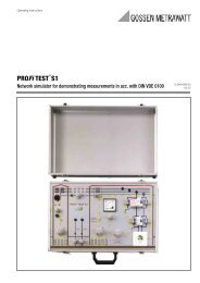
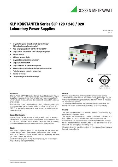
Application<br />
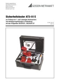
The <strong>SLP</strong>-<strong>KONSTANTER</strong> series (Single Output Laboratory Power<br />
Supplies) includes single-channel laboratory power supplies for<br />
universal use in research and development, production, training<br />
and service.<br />
The instruments are capable of maintaining either constant voltage<br />
or constant current levels, and are deliver <strong>120</strong> W, <strong>240</strong> W or<br />
<strong>320</strong> W of nominal power over a wide range thanks to the autoranging<br />
output.<br />
Setpoint Configuration<br />
Precision manual adjustment of voltage and current is accomplished<br />
with ten-turn potentiometers whose setting ranges Ulim<br />
and Ilim can be limited with the help of a screwdriver, in order to<br />
prevent inadvertent adjustment to undesirably high values.<br />
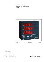
Display<br />
Two large, 3½ place digital LED displays indicate the measured<br />
output voltage and output current. Furthermore, they can be<br />
switched to setpoint display as well, which is especially advantageous<br />
for current adjustment.<br />
Control mode displays in the characteristic curve field indicate<br />
respective operating conditions.<br />
GMC-I Messtechnik GmbH<br />
QUALITY MANAGEMENT SYSTEM<br />
DQS Certified per<br />
DIN EN ISO 9001:2008<br />
Reg. No. 446534QM08 UM<br />
Outputs<br />
Floating outputs are available at both front and rear panels.<br />
Activation or deactivation is accomplished by pressing a key, or<br />
with a signal to the integrated analog interface which is included<br />
as standard equipment.<br />
As soon as sensor cables are connected to the terminals, the<br />
<strong>KONSTANTER</strong> is automatically switched to remote sensing.<br />
Housing<br />
The quiet, temperature controlled fan prevents unnecessarily high<br />
noise levels in working areas.<br />
The rugged metal housing is closed at both top and bottom, and<br />
is equipped with mounting feet and a tilt stand at the rear.<br />
Several units can be quickly and easily fastened to one another<br />
for the creation of multi-channel units, or can be installed to a 19"<br />
rack with the appropriate mounting sets.<br />
Only one electrical outlet is required for the supply of mains power<br />
to multi-channel units.
<strong>SLP</strong> <strong>KONSTANTER</strong> <strong>Series</strong> <strong>SLP</strong> <strong>120</strong> / <strong>240</strong> / <strong>320</strong><br />
Laboratory Power Supplies<br />
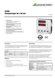
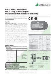
Output Working Range<br />
U/V<br />
Unom. 0.5<br />
U nom.<br />
0<br />
Analog Interface<br />
P nom. Short-Time<br />
Operating Range<br />
0.5 I nom.<br />
I nom.<br />
Connection 11-pole plug-in terminal strip<br />
Reference potential Output negative pole<br />
floating TRG input<br />
Connector Pin Assignments:<br />
PIN Designation Function<br />
1 SIG1 OUT status signal output for input ON / OFF<br />
(open collector, max. 30 V – / 20 mA)<br />
2 SIG2 OUT status signal output control mode CV / CC<br />
(open collector, max. 30 V – / 20 mA)<br />
3 TRG IN + digital control input for input ON / OFF<br />
4 TRG IN –<br />
(low: < 1 V, high: 4 ... 26 V), floating input<br />
5 +15 V auxiliary voltage: +15 V / max. 40 mA<br />
6 AGND<br />
reference point connected to –output with<br />
reversible fuse<br />
7 Uset – analog, inverted voltage control input<br />
(0 ... –5 V corresponds to 0 ... Unom. , Ri = 10 kΩ)<br />
8 Uset+ analog voltage control input<br />
(0 ... +5 V corresponds to 0 ... Unom., Ri = 10 kΩ)<br />
9 Iset+ analog current control input<br />
(0 ... +5 V corresponds to 0 ... Inom., Ri = 10 kΩ)<br />
10 U-MON output voltage measurement output<br />
(0 ... 10 V corresponds to 0 ... Unom. , Ri = 9.8 kΩ<br />
11 I-MON output current measurement output<br />
0 ... 10 V correspond to 0 ... Inom., Ri = 9.4 kΩ)<br />
I/A<br />
Voltage<br />
Setting Range<br />
Current<br />
Setting Range<br />
Applicable Regulations and Standards<br />
IEC 61010-1/EN 61010-1/<br />
VDE 0411-1<br />
VDE 0160:1988 + A1:1989<br />
class W1<br />
EN 60950:1992<br />
VDE 0805:1990<br />
EN 60529<br />
VDE 0470 Part 1<br />
Safety requirements for electrical equipment<br />
for measurement, control and laboratory use<br />
– General requirements<br />
Equipment of power systems with electronic<br />
components<br />
Safety of IT systems<br />
Test instruments and test procedures<br />
– Protection provided by enclosures (IP code)<br />
IEC 68-2-6:1990 Vibration resistance<br />
IEC 68-2-27:1989 Impact resistance<br />
EN 61326-1:1997 Electromagnetic compatibility (CEM)<br />
+ A1: 1998<br />
Product standard<br />
EN 55022:1998 class A<br />
EN 61000-4-2:1995<br />
EN 61000-4-3:1996 +<br />
A1:1998<br />
EN 61000-4-4:1995<br />
EN 61000-4-5:1995<br />
EN 61000-4-6:1996<br />
EN 61000-4-11:1994<br />
Electromagnetic Compatibility (CEM)<br />
Generic standard interference emission –<br />
industrial sector<br />
Electromagnetic Compatibility (CEM)<br />
Generic standard interference immunity –<br />
industrial sector<br />
2 GMC-I Messtechnik GmbH
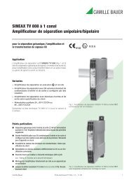
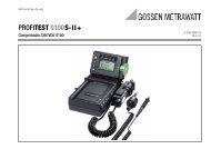
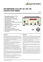
Dimensional Drawing (benchtop instrument)<br />
88<br />
14<br />
All dimensions in mm<br />
40V 40V/6A<br />
<strong>KONSTANTER</strong> <strong>SLP</strong> <strong>240</strong>-40<br />
<strong>240</strong>W<br />
CV<br />
20V/12A<br />
CC<br />
12A<br />
POWER<br />
OUTPUT<br />
ON<br />
OFF<br />
<strong>SLP</strong> <strong>KONSTANTER</strong> <strong>Series</strong> <strong>SLP</strong> <strong>120</strong> / <strong>240</strong> / <strong>320</strong><br />
Laboratory Power Supplies<br />
221.5<br />
Volt Amp<br />
Ulim DISPLAY Ilim<br />
Uset/Iset<br />
Uset<br />
Iset<br />
397.5<br />
380.5<br />
SIG1 OUT<br />
SIG2 OUT<br />
TRG IN<br />
+ TRG IN<br />
15V<br />
AGND<br />
Uset<br />
Uset<br />
Iset<br />
U-MON<br />
I-MON<br />
-<br />
+<br />
-<br />
+<br />
+<br />
ANALOG INTERFACE<br />
230V 50-60Hz<br />
FUSE T4/250V<br />
GMC-I Messtechnik GmbH 3<br />
SENSE<br />
-<br />
-<br />
+ SENSE<br />
+<br />
OUTPUT<br />
Power Supply Outlet<br />
for Use with Multiple<br />
Units<br />
Mains Power<br />
Input
<strong>SLP</strong> <strong>KONSTANTER</strong> <strong>Series</strong> <strong>SLP</strong> <strong>120</strong> / <strong>240</strong> / <strong>320</strong><br />
Laboratory Power Supplies<br />
Characteristic Values, <strong>120</strong> W <strong>Series</strong><br />
Unless otherwise indicated, all entries represent maximum values and are valid within an operating temperature range of 0 to 50° C, the<br />
nominal power range and a line voltage range of 230 V ± 10% after a warm-up period of 30 minutes.<br />
Description (abbreviated designation) <strong>SLP</strong> <strong>120</strong>-20 <strong>SLP</strong> <strong>120</strong>-40 <strong>SLP</strong> <strong>120</strong>-80<br />
Type 32 N 20 R 10 32 N 40 R 6 32 N 80 R 3<br />
Nominal Output Data Voltage Setting Range 0 ... 20 V 0 ... 40 V 0 ... 80 V<br />
Current Setting Range 0 ... 10 A 0 ... 6 A 0 ... 3 A<br />
Continuous Power at Tu ≤ 40° C max. <strong>120</strong> W max. <strong>120</strong> W max. <strong>120</strong> W<br />
Short-Time Rating for t < 90 s / Tu ≤ 25° C max. 200 W max. <strong>240</strong> W max. <strong>240</strong> W<br />
Output Operating Characteristics<br />
Current Derating at Tu > 40° C – 0.25 A / K – 0.15 A / K – 0.07 A / K<br />
Overall Setting Tolerance at 23 ± 5° C<br />
Voltage 0.2 % + 50 mV<br />
0.2 % + 150 mV 0.2 % + 250 mV<br />
with Reference to 3½ Place Setpoint Display<br />
including System Deviation for Load / Line<br />
Current 0.5 % + 45 mA<br />
0.5 % + 35 mA<br />
0.5 % + 20 mA<br />
Static System Deviation 1)<br />
at 100% Load Variation 1)<br />
Voltage<br />
Current<br />
15 mV<br />
20 mA<br />
10 mV<br />
10 mA<br />
10 mV<br />
10 mA<br />
Static System Deviation 1)<br />
at 10% Line Voltage Variation 1)<br />
Voltage<br />
Current<br />
5 mV<br />
8 mA<br />
5 mV<br />
5 mA<br />
5 mV<br />
5 mA<br />
Residual Ripple 1) Voltage (10 Hz ... 10 MHz)<br />
Current (10 Hz ... 1 MHz)<br />
10 mVeff 25 mAeff 10 mVeff 20 mAeff 10 mVeff 10 mAeff Common-Mode Interference (10 Hz ... 1 MHz) 0.5 mA eff 0.5 mA eff 0.5 mA eff<br />
Settling Time (voltage)<br />
with Sudden Load Variations of 10 to 90% Inom. Under and Overshooting with<br />
Sudden Load Variations of 50 A / ms<br />
Response Time (voltage)<br />
with Setpoint Change 0 → 100%<br />
with Setpoint Change 100% → 0<br />
Response Time (current)<br />
with Setpoint Change 0 → 100%<br />
with Setpoint Change 100% → 0<br />
Measurement Value Display (3½ place)<br />
Tolerance<br />
Δ I = 80%<br />
Tolerance<br />
Open-Circuit / Nominal Load<br />
Open-Circuit / Nominal Load<br />
Tolerance<br />
Short-Circuit / Nominal Load<br />
Short-Circuit / Nominal Load<br />
Measuring Resolution Voltage<br />
Current<br />
Measuring Accuracy at 23 ± 5° C<br />
with Reference to the respective Measurement Value<br />
Protective Functions<br />
1) Indicated values are increased by a factor of approximately 1.2 within a mains input voltage range of –10% to –15%.<br />
4 GMC-I Messtechnik GmbH<br />
40 mV<br />
200 μs<br />
80 mV<br />
200 μs<br />
80 mV<br />
200 μs<br />
Δ I = 80% 400 mV 400 mV 800 mV<br />
Voltage<br />
Current<br />
40 mV<br />
1 ms / 1 ms<br />
1 ms / 1 ms<br />
100 mA<br />
< 5 ms / < 5 ms<br />
< 5 ms / < 5 ms<br />
10 mV<br />
10 mA<br />
0.15 % + 25 mV<br />
0.5 % + 30 mA<br />
80 mV<br />
1 ms / 1 ms<br />
1 ms / 1 ms<br />
60 mA<br />
< 5 ms / < 5 ms<br />
< 5 ms / < 5 ms<br />
100 mV<br />
10 mA<br />
0.2 % + <strong>120</strong> mV<br />
0.5 % + 25 mA<br />
160 mV<br />
4 ms / 4ms<br />
4 ms / 4ms<br />
30 mA<br />
< 10 ms / < 10 ms<br />
< 10 ms / < 10 ms<br />
100 mV<br />
10 mA<br />
0.2 % + 150 mV<br />
0.5 % + 20 mA<br />
Output Overvoltage Protection Threshold 25 ± 1 V 50 ± 2 V 100 ± 4 V<br />
Protection against Pole Reversal – Load Capacity Continuous 10 A 6 A 3 A<br />
Reverse Voltage Resistance<br />
General<br />
Continuous 40 V 80 V 100 V<br />
Power Supply 1)<br />
at Nominal Load 230 V~ +10 / −15 % 230 V~ +10 / −15 % 230 V~ +10 / −15 %<br />
in Standby Mode 47 ... 63 Hz<br />
47 ... 63 Hz<br />
47 ... 63 Hz<br />
Power Consumption at max. Short-Time Power 280 VA; 180 W<br />
280 VA; 150 W<br />
280 VA; 170 W<br />
at Nominal Load 45 VA; 15 W<br />
45 VA; 15 W<br />
45 VA; 15 W<br />
Typical<br />
450 VA<br />
500 VA<br />
500 VA<br />
Efficiency at Nominal Load > 70 % > 80 % > 80 %<br />
Switching Frequency in Standby Mode<br />
at max. Short-Time Power<br />
200 kHz 200 kHz 200 kHz<br />
Article Number K220A K221A K222A
Characteristic Values, <strong>240</strong> W <strong>Series</strong><br />
<strong>SLP</strong> <strong>KONSTANTER</strong> <strong>Series</strong> <strong>SLP</strong> <strong>120</strong> / <strong>240</strong> / <strong>320</strong><br />
Laboratory Power Supplies<br />
Unless otherwise indicated, all entries represent maximum values and are valid within an operating temperature range of 0 to 50° C, the<br />
nominal power range and a line voltage range of 230 V ± 10% after a warm-up period of 30 minutes.<br />
Description (abbreviated designation) <strong>SLP</strong> <strong>240</strong>-20 <strong>SLP</strong> <strong>240</strong>-40 <strong>SLP</strong> <strong>240</strong>-80<br />
Type 32 N 20 R 20 32 N 40 R 12 32 N 80 R 6<br />
Nominal Output Data Voltage Setting Range 0 ... 20 V 0 ... 40 V 0 ... 80 V<br />
Current Setting Range 0 ... 20 A 0 ... 12 A 0 ... 6 A<br />
Continuous Power at Tu ≤ 40° C max. <strong>240</strong> W max. <strong>240</strong> W max. <strong>240</strong> W<br />
Short-Time Rating for t < 90 s / Tu ≤ 25° C max. <strong>320</strong> W max. 360 W max. 360 W<br />
Output Operating Characteristics<br />
Current Derating at Tu > 40° C – 0.5 A / K – 0.3 A / K – 0.15 A / K<br />
Overall Setting Tolerance at 23 ± 5° C<br />
Voltage 0.2 % + 100 mV<br />
0.2 % + 150 mV 0.2 % + 250 mV<br />
with Reference to 3½ Place Setpoint Display<br />
including System Deviation for Load / Line<br />
Current 0.5 % + 55 mA<br />
0.5 % + 45 mA<br />
0.5 % + 35 mA<br />
Static System Deviation 1)<br />
at 100% Load Variation 1)<br />
Voltage<br />
Current<br />
25 mV<br />
30 mA<br />
18 mV<br />
30 mA<br />
18 mV<br />
15 mA<br />
Static System Deviation 1)<br />
at 10% Line Voltage Variation 1)<br />
Voltage<br />
Current<br />
5 mV<br />
8 mA<br />
5 mV<br />
8 mA<br />
5 mV<br />
5 mA<br />
Residual Ripple 1) Voltage (10 Hz ... 10 MHz)<br />
Current (10 Hz ... 1 MHz)<br />
15 mVeff 50 mAeff 15 mVeff 25 mAeff 15 mVeff 20 mAeff Common-Mode Interference (10 Hz ... 1 MHz) 0.5 mA eff 0.5 mA eff 0.5 mA eff<br />
Settling Time (voltage)<br />
with Sudden Load Variations of 10 to 90% Inom. Under and Overshooting with<br />
Sudden Load Variations of 50 A / ms<br />
Response Time (voltage)<br />
with Setpoint Change 0 → 100%<br />
with Setpoint Change 100% → 0<br />
Response Time (current)<br />
with Setpoint Change 0 → 100%<br />
with Setpoint Change 100% → 0<br />
Measurement Value Display (3½ place)<br />
Tolerance<br />
Δ I = 80%<br />
Tolerance<br />
Open-Circuit / Nominal Load<br />
Open-Circuit / Nominal Load<br />
Tolerance<br />
Short-Circuit / Nominal Load<br />
Short-Circuit / Nominal Load<br />
Measuring Resolution Voltage<br />
Current<br />
Measuring Accuracy at 23 ± 5° C<br />
with Reference to the respective Measurement Value<br />
Protective Functions<br />
1) Indicated values are increased by a factor of approximately 1.2 within a mains input voltage range of –10% to –15%.<br />
GMC-I Messtechnik GmbH 5<br />
40 mV<br />
400 μs<br />
80 mV<br />
200 μs<br />
160 mV<br />
200 μs<br />
Δ I = 80% 400 mV 400 mV 800 mV<br />
Voltage<br />
Current<br />
40 mV<br />
1 ms / 1 ms<br />
1 ms / 1 ms<br />
200 mA<br />
< 5 ms / < 5 ms<br />
< 5 ms / < 5 ms<br />
10 mV<br />
10 mA<br />
0.2 % + 50 mV<br />
0.5 % + 25 mA<br />
80 mV<br />
1 ms / 1 ms<br />
1 ms / 1 ms<br />
<strong>120</strong> mA<br />
< 5 ms / < 5 ms<br />
< 5 ms / < 5 ms<br />
100 mV<br />
10 mA<br />
0.2 % + <strong>120</strong> mV<br />
0.5 % + 30 mA<br />
160 mV<br />
4 ms / 4ms<br />
4 ms / 4ms<br />
60 mA<br />
< 10 ms / < 10 ms<br />
< 10 ms / < 10 ms<br />
100 mV<br />
10 mA<br />
0.2 % + <strong>120</strong> mV<br />
0.5 % + 25 mA<br />
Output Overvoltage Protection Threshold 25 ± 1 V 50 ± 2 V 100 ± 4 V<br />
Protection against Pole Reversal – Load Capacity Continuous 20 A 12 A 6 A<br />
Reverse Voltage Resistance<br />
General<br />
Continuous 40 V 80 V 100 V<br />
Power Supply1) at Nominal Load 230 V~ +10 / −15 % 230 V~ +10 / −15 % 230 V~ +10 / −15 %<br />
in Standby Mode 47 ... 63 Hz<br />
47 ... 63 Hz<br />
47 ... 63 Hz<br />
Power Consumption at max. Short-Time Power 510 VA; 350 W<br />
500 VA; 340 W<br />
500 VA; 340 W<br />
at Nominal Load 45 VA; 15 W<br />
45 VA; 15 W<br />
45 VA; 15 W<br />
Typical<br />
620 VA<br />
690 VA<br />
690 VA<br />
Efficiency at Nominal Load > 68 % > 70 % > 70 %<br />
Switching Frequency in Standby Mode<br />
at max. Short-Time Power<br />
200 kHz 200 kHz 200 kHz<br />
Article Number K230A K231A K232A
<strong>SLP</strong> <strong>KONSTANTER</strong> <strong>Series</strong> <strong>SLP</strong> <strong>120</strong> / <strong>240</strong> / <strong>320</strong><br />
Laboratory Power Supplies<br />
Characteristic Values, <strong>320</strong> W <strong>Series</strong><br />
Unless otherwise indicated, all entries represent maximum values and are valid within an operating temperature range of 0 to 50° C, the<br />
nominal power range and a line voltage range of 230 V ± 10% after a warm-up period of 30 minutes.<br />
Description (abbreviated designation) <strong>SLP</strong> <strong>320</strong>-32<br />
Type 32 N 32 R 18<br />
Nominal Output Data Voltage Setting Range 0 ... 32 V<br />
Current Setting Range 0 ... 18 A<br />
Continuous Power at Tu ≤ 40° C max. <strong>320</strong> W<br />
Short-Time Rating for t < 90 s / Tu ≤ 25° C max. 430 W<br />
Output Operating Characteristics<br />
Current Derating at Tu > 40° C – 0.5 A / K<br />
Overall Setting Tolerance at 23 ± 5° C<br />
Voltage 0.2 % + 150 mV<br />
with Reference to 3½ Place Setpoint Display<br />
including System Deviation for Load / Line<br />
Current 0.5 % + 50 mA<br />
Static System Deviation 1)<br />
at 100% Load Variation 1)<br />
Voltage<br />
Current<br />
30 mV<br />
40 mA<br />
Static System Deviation 1)<br />
at 10% Line Voltage Variation 1)<br />
Voltage<br />
Current<br />
10 mV<br />
20 mA<br />
Residual Ripple 1) Voltage (10 Hz ... 10 MHz)<br />
Current (10 Hz ... 1 MHz)<br />
30 mVeff 50 mAeff Common-Mode Interference (10 Hz ... 1 MHz) 0.5 mA eff<br />
Settling Time (voltage)<br />
with Sudden Load Variations of 10 to 90% Inom. Under and Overshooting with<br />
Sudden Load Variations of 50 A / ms<br />
Response Time (voltage)<br />
with Setpoint Change 0 → 100%<br />
with Setpoint Change 100% → 0<br />
Response Time (current)<br />
with Setpoint Change 0 → 100%<br />
with Setpoint Change 100% → 0<br />
Measurement Value Display (3½ place)<br />
Tolerance<br />
Δ I = 80%<br />
Tolerance<br />
Open-Circuit / Nominal Load<br />
Open-Circuit / Nominal Load<br />
Tolerance<br />
Short-Circuit / Nominal Load<br />
Short-Circuit / Nominal Load<br />
Measuring Resolution Voltage<br />
Current<br />
Measuring Accuracy at 23 ± 5° C<br />
with Reference to the respective Measurement Value<br />
Protective Functions<br />
1) Indicated values are increased by a factor of approximately 1.2 within a mains input voltage range of –10% to –15%.<br />
6 GMC-I Messtechnik GmbH<br />
64 mV<br />
200 μs<br />
Δ I = 80% 400 mV<br />
Voltage<br />
Current<br />
64 mV<br />
1 ms / 1 ms<br />
1 ms / 1 ms<br />
180 mA<br />
< 5 ms / < 5 ms<br />
< 5 ms / < 5 ms<br />
100 mV<br />
10 mA<br />
0.2 % + <strong>120</strong> mV<br />
0.5 % + 40 mA<br />
Output Overvoltage Protection Threshold 40 ± 1 V<br />
Protection against Pole Reversal – Load Capacity Continuous 20 A<br />
Reverse Voltage Resistance<br />
General<br />
Continuous 64 V<br />
Power Supply1) at Nominal Load 230 V~ +10 / −15 %<br />
in Standby Mode 47 ... 63 Hz<br />
Power Consumption at max. Short-Time Power 650 VA; 460 W<br />
at Nominal Load 50 VA; 15 W<br />
Typical<br />
770 VA<br />
Efficiency at Nominal Load > 69 %<br />
Switching Frequency in Standby Mode<br />
at max. Short-Time Power<br />
200 kHz<br />
Article Number K234A
Ambient Conditions<br />
Vibration Resistance IEC 68-2-6: 1990<br />
10 ... 55 Hz, 0.3 mm, 1 oct. / min.<br />
3 x 30 min.<br />
Impact Resistance IEC 68-2-27: 1989<br />
15 gr., 11 ms, semi-sinusoidal,<br />
3 x 6 impacts<br />
Temperature Range operation: 0 ... 50° C at > 40° C current<br />
derating<br />
storage: –25 ... +75° C<br />
Humidity operation: ≤ 75% relative humidity,<br />
no condensation allowed<br />
Cooling with built-in fan<br />
air intake: side panel<br />
air outlet: rear panel<br />
Power Supply<br />
Connectors In: 10 A IEC inlet plug connector<br />
Out: 10 A IEC inlet socket connector,<br />
no switch, no fuse<br />
Line Voltage 230 V~, +10 / –15%, 47 ... 63 Hz<br />
Power Consumption see Characteristic Values<br />
Inrush Current max. 50 A s<br />
Mains Fusing 1 ea. T 4 A / 250 V (6.3 x 32 mm, UL)<br />
internal: 1 ea. T 5 A / 250 V (5 x 20 mm)<br />
Output<br />
Connectors<br />
Output front panel: 2 ea. 4 mm safety jacks<br />
rear panel: 6-pin plug-in terminal strip<br />
Sensor rear panel: 6-pin plug-in terminal strip<br />
Regulator primary switched-mode regulator with BET<br />
Operating Modes adjustable constant voltage / constant current<br />
source with automatic sharp transition<br />
Output Isolation floating output with “protective separation”<br />
from the mains inlet, max. allowable potential<br />
output–ground: <strong>120</strong> V,<br />
capacitance output–ground (housing): 60 nF<br />
Electrical Safety<br />
Safety Class I<br />
Overvoltage<br />
Category: II for mains inlet<br />
I for output and interface<br />
Contamination Level 2<br />
Earth Leakage<br />
Current typ. 2.5 mA<br />
Electrical Isolation test voltage<br />
Mains / Output–PE 1.35 kV∼<br />
Mains–Output 2.7 kV∼ (type test: 3.7 kV~7 kV~)<br />
<strong>SLP</strong> <strong>KONSTANTER</strong> <strong>Series</strong> <strong>SLP</strong> <strong>120</strong> / <strong>240</strong> / <strong>320</strong><br />
Laboratory Power Supplies<br />
Electromagnetic Compatibility CEM<br />
Product standard EN 61326-1:1997 + A1: 1998<br />
Interference Emission EN 55022:1998 class A<br />
Interference Immunity EN 61000-4-2:1995 Feature A<br />
EN 61000-4-3:1996 + A1:1998<br />
Feature B<br />
EN 61000-4-4:1995 Feature B<br />
EN 61000-4-5:1995 Feature B<br />
EN 61000-4-6:1996 Feature B<br />
EN 61000-4-11:1994 Feature B<br />
Mechanical Design<br />
Protection IP 20 for housing in accordance with<br />
IEC 529: 1989<br />
EN 60529: 1991<br />
VDE 0470-1: 1992<br />
Type benchtop instrument,<br />
suitable for rack mounting<br />
Dimensions<br />
(W x H x D) benchtop unit: 221.5 x 102 x 397.5 mm<br />
19" rack unit: ½19" x 2 standard height<br />
units x 400 mm<br />
Weight approx. 2.8 kg<br />
GMC-I Messtechnik GmbH 7
<strong>SLP</strong> <strong>KONSTANTER</strong> <strong>Series</strong> <strong>SLP</strong> <strong>120</strong> / <strong>240</strong> / <strong>320</strong><br />
Laboratory Power Supplies<br />
Accessories<br />
Description Comment Article No.<br />
19" Adapter, 1 x 32 N Required for mounting 1 type 32 N ...<br />
instrument to a 19" rack K990A<br />
19" Adapter, 2 x 32 N Required for mounting 2 type 32 N ...<br />
instruments to a 19" rack K990B<br />
Mains Jumper Cable,<br />
0.4 meters long<br />
Order Information<br />
Edited in Germany • Subject to change without notice • A pdf version is available on the internet<br />
GMC-I Messtechnik GmbH<br />
Südwestpark 15<br />
90449 Nürnberg • Germany<br />
The cable is equipped with one 10 A inlet<br />
connector plug and one 10 A inlet connector<br />
socket.<br />
Used for cascading mains power when several<br />
instruments are mechanically connected to a<br />
single multi-channel unit. The system thus<br />
requires only one mains outlet. K991A<br />
Description (Abbreviated Designation) Type Article No<br />
Konstanter <strong>SLP</strong> <strong>120</strong>-20 32 N 20 R 10 K220A<br />
Konstanter <strong>SLP</strong> <strong>120</strong>-40 32 N 40 R 6 K221A<br />
Konstanter <strong>SLP</strong> <strong>120</strong>-80 32 N 80 R 3 K222A<br />
Konstanter <strong>SLP</strong> <strong>240</strong>-20 32 N 20 R 20 K230A<br />
Konstanter <strong>SLP</strong> <strong>240</strong>-40 32 N 40 R 12 K231A<br />
Konstanter <strong>SLP</strong> <strong>240</strong>-80 32 N 80 R 6 K232A<br />
Konstanter <strong>SLP</strong> <strong>320</strong>-32 32 N 32 R 1 K234A<br />
Phone +49 911 8602-111<br />
Fax +49 911 8602-777<br />
E-Mail info@gossenmetrawatt.com<br />
www.gossenmetrawatt.com