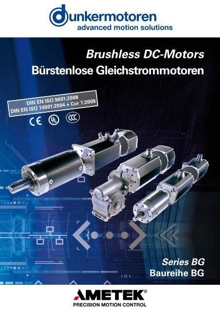
Bürstenlose Gleichstrommotoren Baureihe BG - Dunkermotoren
Bürstenlose Gleichstrommotoren Baureihe BG - Dunkermotoren
Bürstenlose Gleichstrommotoren Baureihe BG - Dunkermotoren

Create successful ePaper yourself
Turn your PDF publications into a flip-book with our unique Google optimized e-Paper software.
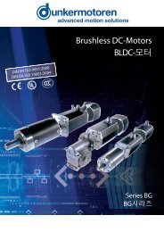
Brushless DC-Motors<br />
Bürstenlose <strong>Gleichstrommotoren</strong><br />
DIN EN ISO 9001:2008<br />
DIN EN ISO 14001:2004 + Cor 1:2009<br />
Series <strong>BG</strong><br />
<strong>Baureihe</strong> <strong>BG</strong>
Foreword / Vorwort<br />
To Our Valued Customers,<br />
<strong>Dunkermotoren</strong> is a world class leader in high quality<br />
motion control solutions to meet the ever increasing<br />
demands for cost effective and reliable drive solutions.<br />
Our comprehensive product range offers the flexibility<br />
to provide customized solutions as well as standardized<br />
components.<br />
The catalog represents <strong>Dunkermotoren</strong>´s years of<br />
engineering excellence.<br />
The <strong>Dunkermotoren</strong> Team will continue to utilize our<br />
outstanding engineering and industrial capabilities to meet<br />
the requirements helping you to succeed.<br />
Wishing you great success in your business.<br />
Nikolaus Gräf<br />
General Manager<br />
Liebe Kunden,<br />
als führender Hersteller der Antriebstechnik bieten wir<br />
Ihnen wirtschaftliche, effiziente und qualitativ hochwertige<br />
Komplettlösungen.<br />
Unser umfassendes Produkt- und Leistungsspektrum<br />
ermöglicht Ihnen ein hohes Maß an Flexibilität: Ob<br />
standardisierte Komponenten oder kundenspezifische<br />
Anforderungen – bei uns finden Sie garantiert die<br />
passende Lösung.<br />
Mit diesem Katalog können Sie sich einen Überblick<br />
über unsere innovativen und richtungsweisenden Produkte<br />
verschaffen.<br />
Das <strong>Dunkermotoren</strong>-Team berät Sie gerne engagiert und<br />
kompetent. Denn: Ihr Erfolg ist unser Ziel.<br />
In diesem Sinne freuen wir uns auf Sie und wünschen<br />
Ihnen alles Gute.<br />
Ihr Nikolaus Gräf<br />
General Manager<br />
2
Content / Inhalt<br />
2 Foreword / Vorwort<br />
3 Content / Inhalt<br />
4 Why <strong>Dunkermotoren</strong> / Gute Gründe<br />
6 Our Product Range / Unser modulares Lieferprogramm<br />
7 Applications / Anwendungen<br />
8 Brushless DC Motors <strong>BG</strong> / Bürstenlose <strong>Gleichstrommotoren</strong> <strong>BG</strong><br />
9 <strong>BG</strong> Selection Guide / <strong>BG</strong>-Auswahlübersicht<br />
10 Technical Information / Technische Informationen<br />
11 Engineering Reference / Auslegung des Antriebs<br />
12 Motor <strong>BG</strong> 32 / <strong>BG</strong> 32 KI 10 - 20 W<br />
14 Motor <strong>BG</strong> 42 / <strong>BG</strong> 42 KI 40 - 65 W<br />
16 Controller / Regelelektronik <strong>BG</strong>E 42 / <strong>BG</strong>E 3004A<br />
18 Motor <strong>BG</strong> 44 SI 20 - 40 W<br />
21 Overview <strong>BG</strong> 45 / Übersicht <strong>BG</strong> 45<br />
22 Motor <strong>BG</strong> 45 SI 40 - 75 W<br />
24 Motor <strong>BG</strong> 45 PI 40 - 75 W<br />
26 Motor <strong>BG</strong> 45 CI/PB/EC 40 - 75 W<br />
30 Motor <strong>BG</strong> 45 MI 40 - 75 W<br />
33 Overview <strong>BG</strong> 65 / Übersicht <strong>BG</strong> 65<br />
34 Motor <strong>BG</strong> 65 / <strong>BG</strong> 65 KI 50 - 220 W<br />
36 Motor <strong>BG</strong> 65 SI 50 - 150 W<br />
38 Motor <strong>BG</strong> 65 PI 50 - 150 W<br />
40 Motor <strong>BG</strong> 65 CI/PB/EC 50 - 150 W<br />
44 Motor <strong>BG</strong> 65 MI 50 - 150 W<br />
46 Motor <strong>BG</strong> 65 S 110 - 185 W<br />
48 Motor <strong>BG</strong> 65 S SI 110 - 170 W<br />
50 Motor <strong>BG</strong> 65 S PI 110 - 170 W<br />
52 Motor <strong>BG</strong> 65 S CI 110 - 170 W<br />
54 Motor <strong>BG</strong> 65 S MI 110 - 170 W<br />
57 Overview <strong>BG</strong> 75 / Übersicht <strong>BG</strong> 75<br />
58 Motor <strong>BG</strong> 75 220 - 530W<br />
60 Motor <strong>BG</strong> 75 SI 220 - 450W<br />
62 Motor <strong>BG</strong> 75 PI 220 - 450W<br />
64 Motor <strong>BG</strong> 75 CI/PB/EC 220 - 450W<br />
68 Motor <strong>BG</strong> 75 MI 220 - 450W<br />
70 Controller / Regelelektronik <strong>BG</strong>E 3508 / 6005<br />
72 Controller / Regelelektronik <strong>BG</strong>E 3515 / 6010<br />
74 Controller / Regelelektronik <strong>BG</strong>E 6050<br />
76 Controller / Regelelektronik <strong>BG</strong>E 30100<br />
78 Gateway CANopen Profibus<br />
81 Gears / Getriebe<br />
82 Planetary gearboxes / Planetengetriebe<br />
98 Worm gearboxes / Schneckengetriebe<br />
106 Brakes for BLDC Motors / Bremsen für <strong>BG</strong>-Motoren<br />
108 Incremental Encoders for BLDC Motors / Inkrementalgeber für <strong>BG</strong>-Motoren<br />
110 Absolute encoder for BLDC motors / Absolutwertgeber für <strong>BG</strong>-Motoren<br />
111 Accessories / Zubehör<br />
118 Representatives and Distributors / Vertretungen<br />
© 10/2012<br />
<strong>Dunkermotoren</strong> GmbH<br />
Printed in Germany<br />
3
Why <strong>Dunkermotoren</strong> / Gute Gründe<br />
Technology & Customer Focus<br />
At <strong>Dunkermotoren</strong>, research and development<br />
is a way of life. The company is actively<br />
committed to develop key technologies and<br />
products that are crucial for its growth. Nextgeneration<br />
technology is in the R&D pipeline<br />
today.<br />
Product development is focused on innovations<br />
to help our customers create value and<br />
differentiate themselves from competitors.<br />
Innovation und Kundenorientierung<br />
<strong>Dunkermotoren</strong> ist stolz darauf, vielfach neue<br />
Industrie-Standards in der Antriebsbranche<br />
geschaffen zu haben. Es ist der Anspruch<br />
eines Technologieführers, der Konkurrenz<br />
immer einen entscheidenden Schritt voraus<br />
zu sein.<br />
Unsere innovativen marktorientierten<br />
Antriebslösungen machen unsere Kunden<br />
noch erfolgreicher und helfen ihnen, sich<br />
mit ihren Produkten positiv von denen der<br />
Mitbewerber abzusetzen.<br />
Quality Assurance & Reliability<br />
One of <strong>Dunkermotoren</strong>´s primary objectives<br />
is to offer outstanding quality.<br />
In 1991 <strong>Dunkermotoren</strong> became the world´s<br />
first manufacturers of small motors to be<br />
certified to ISO 9001. In the meantime,<br />
<strong>Dunkermotoren</strong> has won numerous quality<br />
awards.<br />
<strong>Dunkermotoren</strong> regards quality as a comprehensive<br />
process involving all activities in the<br />
factory. Our products are manufactured in<br />
Germany and China on highly automated<br />
production lines. Failure mode and effects<br />
analysis during design and development,<br />
and fully automated testing integrated in the<br />
production line ensure a uniformly high level<br />
of quality.<br />
Qualität & Zuverlässigkeit<br />
Antriebslösungen höchster Qualität sind bei<br />
<strong>Dunkermotoren</strong> eine Selbstverständlichkeit,<br />
fest verankert in Unternehmensgrundsätzen<br />
und Philosophie. Bereits 1991 wurde <strong>Dunkermotoren</strong><br />
als weltweit erster Hersteller von<br />
Kleinmotoren nach ISO 9001 zertifiziert. In<br />
der Zwischenzeit folgten zahlreiche weitere<br />
Auszeichnungen und Zertifizierungen von<br />
Kunden und Vereinigungen.<br />
<strong>Dunkermotoren</strong> versteht Qualität als einen<br />
ganzheitlichen Prozess, der sämtliche betriebliche<br />
Tätigkeiten umfasst.<br />
<strong>Dunkermotoren</strong> produziert in Deutschland und<br />
China; hochautomatisierte Fertigungsstrecken<br />
und vollautomatische Qualitätskontrollen in<br />
den Fertigungslinien gewährleisten ein<br />
konstant hohes Qualitätsniveau.<br />
Flexibility, Delivery Performance &<br />
Complete Motion Solutions<br />
Standardized motors, gears and modular<br />
accessories are available with a higher degree<br />
of flexibility to address specific requirements<br />
in complete motion solutions. For the<br />
customer, this means better control of quality,<br />
reduced inventory and reduced production<br />
time. If any detail does not entirely meet your<br />
requirements, our R&D department will make<br />
modifications at short notice.<br />
<strong>Dunkermotoren</strong>’s Modular System an<br />
optimized logistics, enables prompt delivery<br />
for both stock and customized products.<br />
Delivery time for stock items is 2-5 days and<br />
for customized solutions is 3-7 weeks.<br />
Flexibilität, Lieferperformance und<br />
umfassende Antriebslösungen<br />
Die Produktpalette von <strong>Dunkermotoren</strong> ist<br />
so aufgebaut, dass sich mit standardisierten<br />
Motoren und einem modular aufgebauten<br />
Zubehör eine hohe Flexibilität für umfassende<br />
Antriebslösungen ergibt. Und sollten Sie<br />
einmal ein Produkt benötigen, das es noch<br />
nicht gibt, dann entwickelt unsere<br />
Konstruktionsabteilung kundenspezifische<br />
Sonderlösungen in kürzester Zeit.<br />
Aufgrund der konsequenten Verwirklichung<br />
des Baukastensystems und einer ausgeklügelten<br />
Produktionslogistik bietet <strong>Dunkermotoren</strong><br />
eine bessere Lieferperformance als<br />
die meisten Mitbewerber, bei Lagerprodukten<br />
(Ø 2-5 Tage) wie auch bei kundenspezifischen<br />
Lösungen (Ø 3-7 Wochen).<br />
4
Service & Proximity<br />
Whether home or abroad, <strong>Dunkermotoren</strong>´s<br />
multi-lingual customer service advisers are<br />
always on hand. By worldwide local presence<br />
of <strong>Dunkermotoren</strong> individual responsibility is<br />
given to the interests of the trading partners<br />
- the best drive solution and the most economical<br />
application.<br />
Today and in the future, <strong>Dunkermotoren</strong> will<br />
provide a total service to the customers -<br />
wherever they are.<br />
Service & Kundennähe<br />
Ob im In- oder Ausland, die Kundenberater<br />
von <strong>Dunkermotoren</strong> sind immer vor Ort<br />
präsent und sprechen die Sprache des<br />
Kunden.<br />
Zur bestmöglichen Berücksichtigung der<br />
Interessen des Kunden werden individuelle<br />
Schulungen, Betreuung und Beratung durch<br />
unsere hochkompetenten Account Manager<br />
gewährleistet.<br />
In der Technik wie auch im Vertrieb - die<br />
Mitarbeiter von <strong>Dunkermotoren</strong> scheuen<br />
keine Herausforderung, Ihre Anforderungen<br />
und Wünsche sind Maßstab für Denken und<br />
Handeln.<br />
Sustainable Development<br />
<strong>Dunkermotoren</strong> is fully aware of its role to<br />
promote sustainable development. Therefore<br />
it commits itself to pay particular attention to<br />
the environment conservation while selecting<br />
and using efficiently raw materials and energy<br />
necessary for production, supply and use of<br />
the product.<br />
In 2002 <strong>Dunkermotoren</strong> has introduced the<br />
environmental management system<br />
conforming to the standard ISO 14001.<br />
Umweltschutz und nachhaltige<br />
Entwicklung<br />
<strong>Dunkermotoren</strong> ist sich seiner Rolle,<br />
nachhaltige Entwicklung zu fördern,<br />
bewusst. Deshalb hat sich die Firma dem<br />
Umweltschutz verpflichtet. Ressourcen<br />
werden sparsam und effizient eingesetzt.<br />
Als erster Hersteller von Elektrokleinmotoren<br />
erhielt <strong>Dunkermotoren</strong> im Jahre 2002 die<br />
Umweltmanagementauszeichnung nach<br />
DIN EN ISO 14001.<br />
Therefore / Darum<br />
5
Our Product Range / Unser modulares Lieferprogramm<br />
DC-Motors<br />
<strong>Gleichstrommotoren</strong><br />
Brushless DC Motors, Series <strong>BG</strong><br />
Bürstenlose <strong>Gleichstrommotoren</strong>, <strong>Baureihe</strong> <strong>BG</strong><br />
Rated voltage 12-360 VDC Nennspannung 12-360 VDC<br />
Rated speed 2300-4050 rpm Nenndrehzahl 2300-4050 min -1<br />
Torque 2.6-150 Ncm Drehmoment 2,6-150 Ncm<br />
Power rating 10-530 W Abgabeleistung 10-530 W<br />
DC Motors, Series GR/G<br />
<strong>Gleichstrommotoren</strong>, <strong>Baureihe</strong> GR/G<br />
Rated voltage 3-220 VDC Nennspannung 3-220 VDC<br />
Rated speed 1500-10000 rpm Nenndrehzahl 1500-10000 min -1<br />
Torque 0.47-65 Ncm Drehmoment 0,47-65 Ncm<br />
Power rating 3-240 W Abgabeleistung 3-240 W<br />
AC-Motors<br />
Wechselstrommotoren<br />
AC Motors, Series KD/DR<br />
Dreh- u. Wechselstrommotoren, <strong>Baureihe</strong> KD/DR<br />
Rated voltage 230-400 VAC, 50Hz Nennspannung 230-400 VAC, 50Hz<br />
Power rating 5-86 W Abgabeleistung 5-86 W<br />
Torque 3.6-31.5 Ncm Drehmoment 3,6-31,5 Ncm<br />
Variants 2/4 pole Varianten 2/4 polig<br />
Venetian Blind- and Positioning Drives, Series D / DCD<br />
Jalousie- und Stellantriebe, <strong>Baureihe</strong> D / DCD<br />
Rated voltage 230 VAC, 50 Hz Nennspannung 230 VAC, 50 Hz<br />
Rated speed 11-52 rpm Nenndrehzahl 11-52 min -1<br />
Torque 3-20 Nm Drehmoment 3-20 Nm<br />
Power rating 50-220 W Abgabeleistung 50-220 W<br />
Accessories<br />
Anbauten<br />
Planetary Gearboxes, Series PLG<br />
Planetengetriebe, <strong>Baureihe</strong> PLG<br />
Continuous torque 0.3-160 Nm Dauerdrehmoment 0,3-160 Nm<br />
Ratio 4:1-710:1 Untersetzungsverhältnis 4:1-710:1<br />
Worm Gearboxes, Series SG<br />
Schneckengetriebe, <strong>Baureihe</strong> SG<br />
Continuous torque 1-30 Nm Dauerdrehmoment 1-30 Nm<br />
Ratio 5:1-80:1 Untersetzungsverhältnis 5:1-80:1<br />
Brakes, Series E<br />
Encoders, Series RE/TG/ME<br />
Electronic Control Systems, Series <strong>BG</strong>E/RS<br />
Bremsen, <strong>Baureihe</strong> E<br />
Inkrementalgeber, <strong>Baureihe</strong> RE/TG/ME<br />
Regelelektroniken, <strong>Baureihe</strong> <strong>BG</strong>E/RS<br />
6
Applications / Anwendungen<br />
Some Applications<br />
Industrial Automation<br />
wood machinery<br />
printing industry<br />
paper industry<br />
textile industry<br />
food & beverage machinery<br />
packaging machinery<br />
semiconductor industry<br />
plastics industry<br />
material handling<br />
mechanical handling<br />
Medical devices & laboratory equipment<br />
Door automation<br />
Sun protection<br />
Motive<br />
Beispiele für Anwendungen<br />
Industrielle Automatisierung<br />
Holzbearbeitung<br />
Druckindustrie<br />
Papierindustrie<br />
Textilmaschinen<br />
Lebensmittelmaschinen<br />
Verpackungsmaschinen<br />
Halbleiterindustrie<br />
Kunststoffherstellung<br />
Materialhandling<br />
Lager und Fördertechnik<br />
Medizin- und Labortechnik<br />
Türautomation<br />
Sonnenschutz<br />
Motive<br />
Customized Solutions<br />
The impossible takes a little longer - customer specific<br />
solutions from <strong>Dunkermotoren</strong>!<br />
Take advantage of the full range of knowledge and experience<br />
of our drive specialists.<br />
We will develop the best possible drive unit solution for you<br />
- innovative, objective and application-oriented.<br />
Kundenspezifische Lösungen<br />
Geht nicht gibt´s nicht - Kundenspezifische Lösungen<br />
von <strong>Dunkermotoren</strong>!<br />
Profitieren Sie vom Know-how des Antriebsspezialisten.<br />
Wir realisieren zielgerichtet, innovativ und anwendungsorientiert<br />
die bestmögliche Antriebseinheit für Sie.<br />
7
Brushless DC Motors <strong>BG</strong><br />
Bürstenlose <strong>Gleichstrommotoren</strong> <strong>BG</strong><br />
The <strong>Dunkermotoren</strong> <strong>BG</strong> range of brushless, direct current<br />
motors (EC motors) are notable for:<br />
• Very long life<br />
• High efficiency<br />
• Highly dynamic acceleration<br />
• Good regulation characteristics<br />
• Wide speed range<br />
• High power density<br />
• Maintenance-free<br />
• Robust design<br />
• Integral Hall sensors for rotor position<br />
• Low moment of inertia<br />
• High degree of protection (up to IP65)<br />
• Motor insulation - Class E<br />
• Neodymium magnets<br />
Die bürstenlosen <strong>Gleichstrommotoren</strong> von <strong>Dunkermotoren</strong><br />
(EC-Motoren) der <strong>Baureihe</strong> <strong>BG</strong> zeichnen sich aus durch:<br />
• Sehr hohe Lebensdauer<br />
• Hoher Wirkungsgrad<br />
• Hochdynamische Beschleunigung<br />
• Gute Regelbarkeit<br />
• Großer Drehzahlbereich<br />
• Hohe Leistungsdichte<br />
• Wartungsfreiheit<br />
• Robusten Aufbau<br />
• Integrierten Hallsensoren zur Erfassung der Rotorlage<br />
• Geringes Trägheitsmoment<br />
• Hohe Schutzart (bis IP65 möglich)<br />
• Motor nach Isolierstoffklasse E<br />
• Neodymmagnete<br />
These electronically-commutated DC motors can be<br />
combined with control electronics, gearboxes, and<br />
encoders in a modular system to provide a flexible,<br />
adaptable, market-oriented solution.<br />
You will find further technical information,<br />
layout data, and information on the selection of motors<br />
and gearboxes on page 10, and on the Internet at<br />
Die elektronisch kommutierten <strong>Gleichstrommotoren</strong><br />
ergeben im Baukastensystem zusammen mit Regelelektroniken,<br />
Getrieben, Bremsen und Istwertgebern ein<br />
flexibles, anpassungsfähiges und marktorientiertes<br />
Sortiment.<br />
Weitere technische Informationen, Auslegungen und<br />
Informationen zur richtigen Auswahl von Motoren und<br />
Getrieben erhalten sie auf S. 10 und im Internet bei<br />
www.dunkermotoren.com<br />
www.dunkermotoren.de<br />
8
<strong>BG</strong> Selection Guide<br />
<strong>BG</strong>-Auswahlmöglichkeiten<br />
32x10<br />
32x20<br />
42x15<br />
42x30<br />
44x25<br />
44x50<br />
45x15<br />
45x30<br />
65x25<br />
65x50<br />
65x75<br />
65Sx25<br />
65Sx50<br />
75x25<br />
75x50<br />
75x75<br />
Motors without controller<br />
Motoren ohne Elektronik<br />
KI Commutation Control<br />
SI Speed Control<br />
PI Positioning Control<br />
CI<br />
Interface<br />
PB<br />
Interface<br />
EC<br />
Interface<br />
MI Master integrated<br />
Controller attached<br />
Regelelektronik angebaut<br />
<strong>BG</strong>E 3004A* / <strong>BG</strong>E 42 16<br />
<strong>BG</strong>E 3508 / 6005* 70<br />
<strong>BG</strong>E 3515 / 6010* 72<br />
<strong>BG</strong>E 6050* 74<br />
<strong>BG</strong>E 30100* 76<br />
W 10 20 40 65 20 40 40 75 60 100 140 110 185 250 400 530<br />
Ncm 3 5 11 18 6 11 13 22 20 30 40 35 50 66 110 150<br />
Page/<br />
Seite 12 12 14 14 18 18 21 21 33 33 33 46 46 57 57 57<br />
78<br />
PLG 32 (0.40 - 4 Nm) 82<br />
PLG 32 H (0.40 - 4 Nm) 82<br />
PLG 42 K (0.70 - 3 Nm) 84<br />
PLG 42 S (3.5 - 14 Nm) 86<br />
PLG 52 (1.2 - 24 Nm) 88<br />
PLG 52 H (1.2 - 24 Nm) 90<br />
PLG 60 (5 - 25 Nm) 92<br />
PLG 63 (5 - 100 Nm) 94<br />
PLG 75 (25 - 160 Nm) 96<br />
SG 45 (0.25 - 0.75 Nm) 98<br />
SG 62 (1 - 1.5 Nm) 100<br />
SG 80 (2 - 8 Nm) 102<br />
SG 120 (8 - 30 Nm) 104<br />
E 38 R 106<br />
E 46 A 106<br />
E 90 R 106<br />
E 100 R/A 106<br />
E 300 R/A 106<br />
ELECTRONIC CONTROL SYSTEMS / REGELELEKTRONIKEN<br />
EXTERNAL CONTROLLER / EXTERNE REGELELEKTRONIKEN<br />
GATEWAY CANopen PROFIBUS / GATEWAY CANopen PROFIBUS<br />
GEARBOXES / GETRIEBE<br />
BRAKES / BREMSEN<br />
INCREMENTAL ENCODERS / INKREMENTALGEBER<br />
RE 30 108 * *<br />
RE 56 108<br />
ME integrated 108<br />
AE65 Absolut Encoder 108<br />
Miscellaneous / Verschiedenes 111<br />
ACCESSORIES / ZUBEHÖR<br />
* For motors with Hall sensors and incremental encoder RE 30 attached / * Für Motoren mit Hallsensoren und angebauten Inkrementalgeber RE 30<br />
n Standard / Standard n On request / auf Anfrage<br />
9
Technical Information / Technische Information<br />
PERFORMANCE DATA<br />
Performance figures given in the tables are measured in accordance<br />
with EN60034. These figures are based on the assumption that the<br />
motor is freestanding and that certain other theoretical conditions are<br />
fulfilled. In a real application, the rated torque of a motor will often be<br />
considerably higher. For this reason, the data tables quote the rated<br />
torque measured according to N (lower value) and also the torque with<br />
the motor mounted on a thermally conducting steel plate with the<br />
dimensions 105 x 105 x 10 mm (value in brackets).<br />
LEISTUNGSDATEN<br />
In den Datentabellen sind die Werte gemessen nach EN60034<br />
angegeben. Diese Werte basieren auf der Annahme eines freistehenden<br />
Motors und auf weiteren theoretischen Gegebenheiten. Im reellen<br />
Einsatzfall liegt das Nenndrehmoment des Motors oftmals wesentlich<br />
höher. Deshalb sind in den Datentabellen die Nenndrehmomente<br />
gemessen nach EN (niedrigere Angabe) sowie gemessen bei<br />
Anbringung einer thermisch leitenden Stahlplatte der Größe<br />
105 x 105 x 10 mm (Angabe in Klammern) aufgeführt.<br />
For many applications, it is<br />
sufficiently accurate to take<br />
the most important data<br />
from the motor characteristic<br />
diagrams and data tables.<br />
Although tolerances and<br />
temperature influences are<br />
not taken into account, the<br />
data is accurate enough for<br />
approximate calculations.<br />
The degree of protection<br />
quoted relates only to the<br />
housing – adequate sealing<br />
of the shaft is the<br />
responsibility of the<br />
customer.<br />
current/Strom I (A)<br />
2.8<br />
2.4<br />
2<br />
1.6<br />
1.2<br />
0.8<br />
0.4<br />
0<br />
efficiency/Wirkungsgrad η (%)<br />
70<br />
60<br />
50<br />
40<br />
30<br />
20<br />
10<br />
0<br />
rated speed/Drehzahl n (rpm)<br />
7000<br />
6000<br />
5000 N = f (M)<br />
<br />
4000<br />
3000<br />
2000<br />
η<br />
Continuous operation<br />
Dauerbetrieb<br />
<br />
<br />
Cyclic operation<br />
Zyklischer Betrieb<br />
Destroying operation<br />
Zerstörende Betriebszustände<br />
J = f (M)<br />
<br />
<br />
1000<br />
<br />
<br />
0<br />
-0.8 0 0.8 1.6<br />
M<br />
2.4 N 3.2 4 4.8 5.6 6.4 7.2 8 Ncm<br />
Den Motordiagrammen und Datentabellen<br />
können die für viele<br />
Anwendungen wichtigsten Daten<br />
entnommen werden. Obwohl<br />
Toleranzen und Temperatureinflüsse<br />
nicht berücksichtigt sind, reichen<br />
die Werte für überschlagsmässige<br />
Betrachtungen aus. Die angegebenen<br />
Schutzarten beziehen sich nur auf die<br />
Gehäuse. Die Abdichtung der Welle ist<br />
vom Kunden vorzunehmen.<br />
- Nominal voltage U N<br />
(VDC)<br />
The DC voltage that is applied to the commutation electronics as a<br />
system supply voltage. All rated data in our catalogs are with<br />
reference to this voltage. Motor applications are, however, not<br />
restricted to this voltage.<br />
- Rated torque M N<br />
(Ncm)<br />
The torque that can be produced by the motor, operating continuously,<br />
in an ambient temperature of 20°C.<br />
- Rated speed n N<br />
(min -1 )<br />
The speed of the motor when it is operating at rated torque (6).<br />
- Rated current I N<br />
(A)<br />
The current drawn from a DC source when the motor is operating at<br />
rated torque (7).<br />
- Starting current I A<br />
(A)<br />
The current required to produce the starting torque. For motors with<br />
electronics, the starting current may be higher than the permissible<br />
peak current (4).<br />
- Starting torque M A<br />
(Ncm)<br />
The maximum torque the motor can produce (2).<br />
- Rated power P N<br />
(W)<br />
The output power which the motor can produce continuously; it is<br />
calculated from rated speed and rated torque.<br />
- Moment of inertia of rotor J R<br />
(gcm 2 )<br />
The moment of inertia of the rotor is the factor that determines the<br />
dynamic properties of a motor.<br />
- Peak current I max<br />
(A)<br />
The maximum current for electronics or motors with integral<br />
electronics (5).<br />
- Max. permissible voltage range U max<br />
(VDC)<br />
The minimum and maximum permissible input voltage for electronics<br />
or motors with integral electronics.<br />
- Recommended speed control range n max<br />
(min -1 )<br />
The regulated speed range within which rotor position sensing by Hall<br />
sensors ensures a smooth torque curve. As a rule, this range can be<br />
extended by installing a rotary encoder.<br />
The data in this catalog contain product specifications, but are not a<br />
guarantee of particular properties. The stated values are subject to<br />
tolerances. Any supplementary information and safety instructions given<br />
in the operating manual must be observed with no exceptions. We<br />
reserve the right to make technical changes and to restrict availability.<br />
- Nennspannung U N<br />
(VDC)<br />
Die Gleichspannung, die als Systemversorgungsspannung an die<br />
Kommutierungselektronik angelegt wird. Auf diese Spannung beziehen<br />
sich alle Nenndaten in den Katalogen. Die Motoranwendung ist jedoch<br />
nicht auf diese Spannung beschränkt.<br />
- Nenndrehmoment M N<br />
(Ncm)<br />
Das Moment, das der Motor bei einer Umgebungstemperatur von<br />
20°C im Dauerbetrieb abgeben kann.<br />
- Nenndrehzahl n N<br />
(min -1 )<br />
Die Drehzahl, die sich bei Abgabe des Nenndrehmoments einstellt (6).<br />
- Nennstrom I N<br />
(A)<br />
Der Strom, der der Gleichspannungsquelle entnommen wird, wenn<br />
der Motor bei Nenndrehmoment betrieben wird (7).<br />
- Anlaufstrom I A<br />
(A)<br />
Der Strom, der fließt, um das Anlaufmoment zu erzeugen. Bei<br />
Motoren mit Elektronik kann der Anlaufstrom höher sein als der<br />
zulässige Spitzenstrom (4).<br />
- Anlaufmoment M A<br />
(Ncm)<br />
Das Moment, welches der Motor maximal erzeugen kann (2).<br />
- Nennleistung P N<br />
(W)<br />
Die Abgabeleistung des Motors, welche er dauerhaft erzeugen kann;<br />
berechnet aus Nenndrehzahl und Nenndrehmoment.<br />
- Läufermassenträgheitsmoment J R<br />
(gcm 2 )<br />
Massenträgheitsmoment des Rotors und bestimmende Größe für die<br />
dynamischen Eigenschaften des Motors.<br />
- Spitzenstrom I max<br />
(A)<br />
Der maximal zulässige Strom bei Elektroniken oder Motoren mit<br />
integrierter Elektronik (5).<br />
- Max. zulässiger Spannungsbereich U max<br />
(VDC)<br />
Die minimal und maximal zulässige Eingangsspannung bei<br />
Elektroniken oder Motoren mit integrierter Elektronik.<br />
- Empfohlener Drehzahlregelbereich n max<br />
(min -1 )<br />
Der Drehzahlregelbereich in dem bei Rotorlageerkennung durch Hallsensoren<br />
ein glatter Drehmomentverlauf steuerbar ist. Durch Anbringung eines<br />
Inkrementalencoders kann dieser Bereich in der Regel erweitert werden.<br />
Die Angaben in diesem Katalog enthalten Spezifikationen der Produkte,<br />
nicht aber die Zusicherung von Eigenschaften. Die genannten Werte<br />
unterliegen Toleranzen. Die im Betriebshandbuch angegebenen<br />
Ergänzungen und Sicherheitshinweise sind unbedingt zu beachten.<br />
Liefermöglichkeiten und technische Änderungen vorbehalten.<br />
10
Engineering Reference / Auslegung des Antriebs<br />
MOTOR CHARACTERISTIC DIAGRAMS<br />
- Speed curve (blue)<br />
This curve shows the speed characteristic at constant voltage. Its end<br />
points are the no-load speed n 0<br />
(1) and the theoretical starting torque<br />
M A<br />
(2).<br />
- Current curve (black)<br />
The current curve shows the relationship between current and torque.<br />
Its end points are the no-load current I 0<br />
(3) and the starting current I A<br />
(4).<br />
- Efficiency curve (green)<br />
The efficiency is the relationship between the mechanical power<br />
output and the electrical power input.<br />
The curve shows the efficiency with the motor in cold condition; as<br />
the motor warms up, the curve shifts accordingly.<br />
MOTORDIAGRAMME<br />
- Drehzahlkennlinie (blau)<br />
Diese Kennlinie beschreibt das Drehzahlverhalten bei konstanter<br />
Spannung. Deren Endpunkte zeigen die Leerlaufdrehzahl n 0<br />
(1) und<br />
das theoretische Anlaufmoment M A<br />
(2).<br />
- Stromkennlinie (schwarz)<br />
Die Stromkennlinie stellt die Äquivalenz von Strom und Drehmoment<br />
dar. Deren Endpunkte zeigen den Leerlaufstrom I 0<br />
(3) und den Anlaufstrom<br />
I A<br />
(4).<br />
- Wirkungsgradkennlinie (grün)<br />
Der Wirkungsgrad beschreibt das Verhältnis von abgegebener<br />
mechanischer Leistung zu aufgenommener elektrischer Leistung.<br />
Die Kennlinien beziehen sich auf den Kaltzustand des Motors und<br />
verschieben sich entsprechend bei zunehmender Erwärmung des Motors.<br />
- Rated torque M N<br />
; Starting torque M max<br />
The rated torque (red) is the limit of the continuous operation region<br />
(shaded blue). In the region between the rated torque and the<br />
maximum permissible torque, the motor must only be used<br />
intermittently (shaded orange). Operating conditions above the<br />
maximum permissible torque result in demagnetization of the<br />
permanent magnets (shaded red).<br />
ENGINEERING REFERENCE<br />
In the wide range of <strong>Dunkermotoren</strong> products, you will find a suitable<br />
drive for almost any requirement in powers ranging from 1 - 530 Watt.<br />
Please note also our other product lines and catalogs (DC commutator<br />
motors, AC motors).<br />
The following points should be taken into account when selecting<br />
motors and gearboxes:<br />
- Which type of operation is required (continuous, intermittent or<br />
periodic operation)<br />
- What is the working life expected of the motor<br />
- What torque and speeds are required<br />
- How much space is available for the motor<br />
- How high is the available voltage DC or AC<br />
- Are there special environmental conditions (temperature,<br />
humidity, vibration, ...)<br />
- To what degree can heat from the motor be disposed of<br />
- Are there exceptional axial and radial shaft loads to consider<br />
- What demands are made of the motor control electronics<br />
- Is the motor to be controlled online via a bus system<br />
- Do you need a brake, an encoder or a non-reversing device<br />
By dimensioning a suitable motor, determining the required torque plays<br />
a decisive role in avoiding thermal overload of the motor in service.<br />
In the assembly of a drive system consisting of motor and control<br />
electronics, it is important to ensure that permissible values for the<br />
motor are not exceeded by outputs from the electronics.<br />
Depending on the speed of rotation required, a motor or a motorgearbox<br />
combination may be selected. The choice of a reduction<br />
gearbox will largely depend on the recommended maximum torque<br />
in continuous operation. For intermittent duty, loading above the rated<br />
torque is possible.<br />
When choosing a motor after deciding on the gearbox, the following<br />
applies:<br />
M motor<br />
= M gearbox<br />
/ (i x h)<br />
We will be pleased to carry out a precise adaptation of a motor to your<br />
service conditions.<br />
- Nenndrehmoment M N<br />
; Anlaufdrehmoment M max<br />
Das Kriterium Nenndrehmoment (rot) begrenzt den Dauerbetriebsbereich<br />
(blau schattiert). Im Bereich zwischen Nenndrehmoment und<br />
max. zulässigem Drehmoment darf der Motor nur kurzzeitig betrieben<br />
werden (orange schattiert). Betriebszustände über dem max. zulässigen<br />
Drehmoment führen zur Entmagnetisierung der Dauermagneten<br />
(rot schattiert).<br />
AUSLEGUNG DES ANTRIEBS<br />
In <strong>Dunkermotoren</strong>´s breiter Produktpalette finden Sie für nahezu jede<br />
Anforderung einen passenden Antrieb im Leistungsbereich von<br />
1 - 530 Watt. Bitte beachten Sie auch unsere weiteren Produktlinien und<br />
-kataloge (DC Kollektormotoren, Wechselstrommotoren).<br />
Folgende Punkte sollten bei der Auswahl von Motor und Getriebe<br />
berücksichtigt werden:<br />
- Welche Betriebsart liegt vor (Dauer-, Kurzzeit- oder<br />
Aussetzbetrieb)<br />
- Welche Lebensdauer wird gefordert<br />
- Welches Drehmoment und welche Drehzahl werden benötigt<br />
- Wie viel Raum ist für den Motor verfügbar<br />
- Wie hoch ist die verfügbare Spannung Gleich- oder<br />
Wechselspannung<br />
- Gibt es besondere Umgebungseinflüsse (Temperatur, Feuchtigkeit,<br />
Vibration, ...)<br />
- In welchem Umfang wird die Motorwärme abgeleitet<br />
- Müssen außergewöhnliche axiale und radiale Wellenbelastungen<br />
berücksichtigt werden<br />
- Welchen Steuerungsanforderungen muss die<br />
Steuerungselektronik des Motors genügen<br />
- Werden die Motoren online über ein Bussystem angesteuert<br />
- Benötigen Sie eine Bremse, einen Encoder oder eine<br />
Rücklaufsperre<br />
Für die Auslegung des geeigneten Motors spielt die Ermittlung des<br />
effektiven Drehmomentes die entscheidende Rolle, um zu verhindern,<br />
dass der Motor im Betrieb thermisch überlastet wird. Für die Zusammenstellung<br />
eines Antriebssystems aus Motor und Betriebselektronik<br />
ist zu berücksichtigen, dass die für den Motor zulässigen Werte durch<br />
die Elektronik nicht überschritten werden.<br />
Je nach gewünschter Drehzahl wird man sich entweder für einen Motor<br />
oder einen Getriebemotor entscheiden. Die Wahl des Untersetzungsgetriebes<br />
richtet sich nach dem empfohlenen maximalen Drehmoment<br />
bei Dauerbetrieb. Bei kurzzeitigem Betrieb sind auch Belastungen über<br />
dem Nennmoment möglich.<br />
Zur Auswahl des Motors nach Festlegung des Getriebes gilt:<br />
M Motor<br />
= M Getriebe<br />
/ (i x h)<br />
Gerne erfolgt auf Aufrage eine exakte Anpassung des Motors an Ihre<br />
Betriebsbedingungen.<br />
11
<strong>BG</strong> 32 / <strong>BG</strong> 32 KI, 10 - 20 W<br />
Versions of <strong>BG</strong> 32 / Ausführungen <strong>BG</strong> 32<br />
Page / Seite<br />
Controllers / Regelelektroniken<br />
With gearbox / Als Getriebemotor 81<br />
With brake / Als Bremsmotor 106<br />
n Standard / Standard n On request / auf Anfrage<br />
• Highly dynamic 3-phase BLDC motor with 8-pole neodymium<br />
magnet<br />
• Up to 20 Watt output power<br />
• Compact design<br />
• High power density<br />
• Available in 2 motor lengths<br />
• Version with hall sensors for rotor position detection available<br />
• Can be operated with the external control electronics <strong>BG</strong>E 3004A<br />
• Version KI with integral commutation electronic available<br />
• In this version, the motor is intended for rotation in one direction<br />
only<br />
• There are two connection leads for the DC power supply<br />
• The speed of rotation of the motor is unregulated, as with<br />
conventional DC motor; it depends solely on the supply voltage<br />
and the load<br />
• Can be combined with encoders, brakes and gearboxes within<br />
our modular system<br />
• Hochdynamischer 3-strängiger EC-Motor mit 8-poligem<br />
Neodymmagnet<br />
• Bis 20 Watt Abgabeleistung<br />
• Kompakte Bauform<br />
• Hohe Leistungsdichte<br />
• Verfügbar in 2 Baulängen<br />
• Ausführung mit Hallsensoren zur Rotorlageerfassung verfügbar<br />
• Kann mit der externen Regelelektronik <strong>BG</strong>E 3004A angesteuert werden<br />
• Ausführung KI mit integrierter Kommutierungselektronik verfügbar<br />
• In dieser Ausführung ist der Motor für den Betrieb in eine<br />
Drehrichtung bestimmt<br />
• Der Anschluss erfolgt nur über zwei Anschlusslitzen für die<br />
Gleichspannungsversorgung<br />
• Die Drehzahl des Motors ist wie bei einem DC-Motor ungeregelt<br />
und ist abhängig von der angelegten Spannung und Belastung<br />
• Im modularen Baukasten kombinierbar mit Gebern, Bremsen<br />
und Getrieben<br />
12<br />
Data / Technische Daten <strong>BG</strong> 32x10 <strong>BG</strong> 32x20<br />
Nominal voltage/<br />
Nennspannung VDC 12 24 12 24<br />
Nominal current/<br />
Nennstrom A *) 1.66 0.79 2.53 1.13<br />
Nominal torque/<br />
Nennmoment Ncm *) 2.72 2.67 4.81 4.79<br />
Nominal speed/<br />
Nenndrehzahl rpm *) 4000 3840 4060 3600<br />
Friction torque/<br />
Reibungsmoment Ncm *) 0.4 0.4 0.7 0.7<br />
Peak stall torque/<br />
Max. Anhaltemoment Ncm **) 11 11 21 21<br />
No load speed/<br />
Leerlaufdrehzahl rpm *) 5820 5620 5240 4760<br />
Maximum output power/<br />
Maximale Abgabeleistung W **) 15.8 15.8 26.6 26.6<br />
Torque constant/<br />
Drehmomentkonstante Ncm A -1***) 1.8 3.8 2.0 4.5<br />
Terminal Resistance/<br />
Anschlußwiderstand<br />
Ω****) 1.55 6.96 0.75 3.82<br />
Terminal inductance/<br />
Anschlußinduktivität<br />
mH****) 0.7 3.1 0.37 1.8<br />
Peak current/<br />
Zulässiger Spitzenstrom (2 sec.) A **) 4.2 2.1 9.0 4.5<br />
Rotor inertia/<br />
Rotor Trägheitsmoment gcm 2 6 6 10 10<br />
Weight of motor/<br />
Motorgewicht kg 0.15 0.15 0.20 0.20<br />
*) DJ w<br />
= 100 K; **) J R<br />
= 20°C ***) at nominal point / im Nennpunkt ****) only for hall version / nur für Hall-Version
<strong>BG</strong> 32 / <strong>BG</strong> 32 KI, 10 - 20 W<br />
Dimensions in mm / Maßzeichnung in mm<br />
deep/<br />
deep/<br />
-0.004<br />
( -0.009 )<br />
L<br />
Motor L<br />
<strong>BG</strong> 20x10 48±0.6<br />
<strong>BG</strong> 20x20 58±0.6<br />
Pin assignment / Pinbelegung (<strong>BG</strong> 32 Hall)<br />
5-Pin Hall-Connector 3-Pin Winding-Connector<br />
1 UPower 1 C<br />
2 H1 2 B<br />
3 H2 3 A<br />
4 H3<br />
5 GNDPower<br />
Pin assignment / Pinbelegung (<strong>BG</strong> 32 KI)<br />
5-Pin Signal-Connector 3-Pin Power-Connector<br />
1 UHall 1 U Power<br />
2 IN A 2 GND Power<br />
3 IN B 3 GND Power<br />
4 OUT 1 (Hall)<br />
5 GNDHall<br />
Characteristic diagram / Belastungskennlinien<br />
In accordance with EN 60034<br />
Belastungskennlinien gezeichnet nach EN 60034<br />
7<br />
6<br />
5<br />
70<br />
60<br />
50<br />
7000<br />
6000<br />
5000<br />
η<br />
J=f(M)<br />
ϑ R =20°C<br />
Δϑ W = 100K<br />
14<br />
12<br />
10<br />
70<br />
60<br />
50<br />
7000<br />
6000<br />
5000<br />
η<br />
J=f(M)<br />
ϑ R =20°C<br />
Δϑ W = 100K<br />
4<br />
40<br />
4000<br />
8<br />
40<br />
4000<br />
current/Strom I (A)<br />
3<br />
2<br />
1<br />
0<br />
efficiency/Wirkungsgrad η (%)<br />
30<br />
20<br />
10<br />
0<br />
ratedspeed/Drehzahl n (rpm)<br />
3000<br />
2000<br />
1000<br />
0<br />
M N<br />
N=f(M)<br />
1.2 2.4 3.6 4.8 6 7.2 8.4 9.6 10.8 12 13.2<br />
Ncm<br />
<strong>BG</strong> 32x10, 12V<br />
current/Strom I (A)<br />
6<br />
4<br />
2<br />
0<br />
efficiency/Wirkungsgrad η (%)<br />
30<br />
20<br />
10<br />
0<br />
ratedspeed/Drehzahl n (rpm)<br />
3000<br />
2000<br />
1000<br />
0<br />
M N<br />
N=f(M)<br />
2.5 5 7.5 10 12.5 15 17.5 20 22.5 25 27.5<br />
Ncm<br />
<strong>BG</strong> 32x20, 12V<br />
current/Strom I (A)<br />
3.5<br />
3.0<br />
2.5<br />
2.0<br />
1.5<br />
1.0<br />
0.5<br />
0<br />
efficiency/Wirkungsgrad η (%)<br />
70<br />
60<br />
50<br />
40<br />
30<br />
20<br />
10<br />
0<br />
ratedspeed/Drehzahl n (rpm)<br />
7000<br />
6000<br />
5000<br />
4000<br />
3000<br />
2000<br />
1000<br />
0<br />
η<br />
J=f(M)<br />
ϑ R =20°C<br />
Δϑ W = 100K<br />
M N<br />
N=f(M)<br />
1.2 2.4 3.6 4.8 6 7.2 8.4 9.6 10.8 12 13.2<br />
Ncm<br />
<strong>BG</strong> 32x10, 24V<br />
current/Strom I (A)<br />
5.6<br />
4.8<br />
4.0<br />
3.2<br />
2.4<br />
1.6<br />
0.8<br />
0<br />
efficiency/Wirkungsgrad η (%)<br />
70<br />
60<br />
50<br />
40<br />
30<br />
20<br />
10<br />
0<br />
ratedspeed/Drehzahl n (rpm)<br />
7000<br />
6000<br />
5000<br />
4000<br />
3000<br />
2000<br />
1000<br />
0<br />
η<br />
J=f(M)<br />
ϑ R =20°C<br />
Δϑ W = 100K<br />
M N<br />
N=f(M)<br />
2.5 5 7.5 10 12.5 15 17.5 20 22.5 25 27.5<br />
Ncm<br />
<strong>BG</strong> 32x20, 24V<br />
13
<strong>BG</strong> 42 / <strong>BG</strong> 42 KI, 40 - 65 W<br />
Versions of <strong>BG</strong> 42 / Ausführungen <strong>BG</strong> 42<br />
Page / Seite<br />
Controllers / Regelelektroniken<br />
- motor without controller / Motor ohne Elektronik 14<br />
- with controller attached / mit angebauter Steuerungselektronik (<strong>BG</strong>E 42) 16<br />
- with external controller / mit externer Steuerungselektronik (<strong>BG</strong>E 3004A/3515/6010) 16/72<br />
With incremental encoder / Mit Inkrementalgeber 108<br />
With gearbox / Als Getriebemotor 81<br />
With brake / Als Bremsmotor 106<br />
n Standard / Standard<br />
• Highly dynamic 3-phase EC motor with 8-pole neodymium magnet<br />
• Version with Hall sensors for rotor position detection<br />
• Additional power electronics are needed to run this motor<br />
• Available in 2 motor length<br />
• Cost optimized motor design<br />
• The high power density and compact design make this motor<br />
suitable for numerous application areas<br />
• Good price / performance ratio<br />
• Standard with lead version<br />
• Version KI with integral commutation electronic available<br />
• In this version, the motor is intended for rotation in one direction<br />
only<br />
• There are two connection leads for the DC power supply<br />
• The speed of rotation of the motor is unregulated, as with<br />
conventional DC motor; it depends solely on the supply voltage<br />
and the load<br />
• On request, this motor can be manufactured with different<br />
windings (voltage versions)<br />
• Hochdynamischer 3-strängiger EC-Motor mit 8-poligem<br />
Neodymmagnet<br />
• Ausführung mit Hallsensoren zur Rotorlageerfassung<br />
• Für den Betrieb dieser Motoren ist eine zusätzliche Leistungselektronik<br />
notwendig<br />
• Verfügbar in 2 Baulängen<br />
• Kostenoptimiertes Motordesign<br />
• Die hohe Leistungsdichte und kompakte Bauform gestatten den<br />
Einsatz in zahlreichen Anwendungsgebieten<br />
• Gutes Preis / Leistungsverhältnis<br />
• Standardmäßig mit Litzenausführung<br />
• Ausführung KI mit integrierter Kommutierungselektronik verfügbar<br />
• In dieser Ausführung ist der Motor für den Betrieb in eine<br />
Drehrichtung bestimmt<br />
• Der Anschluss erfolgt nur über zwei Anschlusslitzen für die<br />
Gleichspannungsversorgung<br />
• Die Drehzahl des Motors ist wie bei einem DC-Motor ungeregelt<br />
und ist abhängig von der angelegten Spannung und Belastung<br />
• Diese Motoren werden auf Anfrage noch mit anderen<br />
Wicklungen (Spannungsvarianten) hergestellt<br />
14<br />
Data / Technische Daten <strong>BG</strong> 42x15 <strong>BG</strong> 42x30<br />
Nominal voltage/<br />
Nennspannung VDC 12 24 12 24<br />
Nominal current/<br />
Nennstrom A *) 4.4 2.24 6.8 3.3<br />
Nominal torque/<br />
Nennmoment Ncm *) 10.6 10.8 17.3 17.2<br />
Nominal speed/<br />
Nenndrehzahl rpm *) 3410 3630 3330 3580<br />
Friction torque/<br />
Reibungsmoment Ncm *) 1.1 1.1 1.8 1.7<br />
Peak stall torque/<br />
Max. Anhaltemoment Ncm **) 60.2 74.6 102 152<br />
No load speed/<br />
Leerlaufdrehzahl rpm *) 4340 4390 4190 4110<br />
Maximum output power/<br />
Maximale Abgabeleistung W **) 67.3 86 102 156<br />
Torque constant/<br />
Drehmomentkonstante Ncm A -1***) 2.8 5.5 2.9 5.9<br />
Terminal Resistance/<br />
Anschlußwiderstand<br />
Ω****) 0.28 1.07 0.14 0.53<br />
Terminal inductance/<br />
Anschlußinduktivität<br />
mH****) 0.19 0.75 0.10 0.43<br />
Peak current/<br />
Zulässiger Spitzenstrom (2 sec.) A **) 26 15 40 22<br />
Rotor inertia/<br />
Rotor Trägheitsmoment gcm 2 24 24 44 44<br />
Weight of motor/<br />
Motorgewicht kg 0.36 0.36 0.47 0.47<br />
*) DJ w<br />
= 100 K; **) J R<br />
= 20°C ***) at nominal point / im Nennpunkt ****) only for hall version / nur für Hall-Version
<strong>BG</strong> 42 / <strong>BG</strong> 42 KI, 40 - 65 W<br />
Dimensions in mm / Maßzeichnung in mm<br />
+1.1<br />
Ø 42 -0.2<br />
M3<br />
6 +1 tief<br />
Ø 32±0.1<br />
0.1 A<br />
NS<br />
B<br />
2-0.3<br />
L<br />
2-0.3<br />
A<br />
0.06<br />
AS<br />
C<br />
0.03<br />
-0.004<br />
( -0.009 )<br />
0.1<br />
Ø 32±0.1<br />
B<br />
M3<br />
6 +1 tief<br />
**Ø 22 -0.04<br />
45°<br />
90°<br />
Ø 38<br />
0.1<br />
**Ø 22 -0.04<br />
20±1<br />
45°<br />
90°<br />
300 ±30<br />
ab Flansch<br />
Ø 6 g5<br />
C<br />
C<br />
Version / Ausführung Hall<br />
Version / Ausführung KI<br />
F axial<br />
= max. 90N<br />
F radial<br />
= max. 130N Motor L<br />
<strong>BG</strong> 42x15 65±0.6<br />
<strong>BG</strong> 42x30 80±0.6<br />
Pin assignment / Pinbelegung (<strong>BG</strong> 42 Hall)<br />
Colour/Farbe Power / Signal Colour/Farbe Power / Signal<br />
blue A (motor) red UHall<br />
white B (motor) black GND Hall<br />
grey C (motor)<br />
yellow HS1<br />
green HS2<br />
brown HS3<br />
Characteristic diagram / Belastungskennlinien<br />
Pin assignment / Pinbelegung (<strong>BG</strong> 42 KI)<br />
Colour/Farbe<br />
red<br />
black<br />
yellow<br />
green<br />
brown<br />
Power / Signal<br />
UPower<br />
GND Power<br />
IN A<br />
IN B<br />
OUT 1 (Hall)<br />
In accordance with EN 60034<br />
Belastungskennlinien gezeichnet nach EN 60034<br />
current/Strom I (A)<br />
56<br />
48<br />
40<br />
32<br />
24<br />
16<br />
8<br />
0<br />
efficiency/Wirkungsgrad η (%)<br />
100<br />
80<br />
60<br />
40<br />
20<br />
0<br />
rated speed/Drehzahl n (rpm)<br />
7000<br />
6000<br />
5000<br />
4000<br />
3000<br />
2000<br />
1000<br />
0<br />
N=f(M)<br />
M N<br />
0 10 20 30 40 50 60 70 80 90 100<br />
Ncm<br />
<strong>BG</strong> 42x15, 12 V<br />
η<br />
J=f(M)<br />
ϑ R =20°C<br />
Δϑ W = 100K<br />
current/Strom I (A)<br />
70<br />
60<br />
50<br />
40<br />
30<br />
20<br />
10<br />
0<br />
efficiency/Wirkungsgrad η (%)<br />
100<br />
80<br />
60<br />
40<br />
20<br />
0<br />
ratedspeed/Drehzahl n (rpm)<br />
7000<br />
6000<br />
N=f(M)<br />
5000<br />
4000<br />
3000<br />
2000<br />
1000<br />
0<br />
η<br />
M N<br />
0 15 30 45 60 75 90 105 120 135 150<br />
Ncm<br />
<strong>BG</strong> 42x30, 12 V<br />
J=f(M)<br />
ϑ R =20°C<br />
Δϑ W = 100K<br />
28<br />
24<br />
20<br />
100<br />
7000<br />
6000<br />
5000<br />
N = f (M)<br />
J = f (M)<br />
ϑ R =20°C<br />
Δϑ W = 100K<br />
35<br />
30<br />
25<br />
100<br />
7000<br />
6000<br />
5000<br />
N = f (M)<br />
J = f (M)<br />
ϑ R =20°C<br />
Δϑ W =100K<br />
16<br />
80<br />
4000<br />
η<br />
20<br />
80<br />
4000<br />
η<br />
current/Strom I (A)<br />
12<br />
8<br />
4<br />
0<br />
efficiency/Wirkungsgrad η (%)<br />
60<br />
40<br />
20<br />
0<br />
rated speed/Drehzahl n (rpm)<br />
3000<br />
2000<br />
1000<br />
0<br />
M N<br />
0 10 20 30 40 50 60 70 80 90 100<br />
Ncm<br />
<strong>BG</strong> 42x15, 24 V<br />
current/Strom I (A)<br />
15<br />
10<br />
5<br />
0<br />
efficiency/Wirkungsgrad η (%)<br />
60<br />
40<br />
20<br />
0<br />
rated speed/Drehzahl n (rpm)<br />
3000<br />
2000<br />
1000<br />
0<br />
M N<br />
0 15 30 45 60 75 90 105 120 135 150<br />
Ncm<br />
<strong>BG</strong> 42x30, 24 V<br />
15
<strong>BG</strong>E 42/3004A Controller / Regelelektroniken<br />
• There is an integral potentiometer for setting the speed<br />
• Two connection leads can be used to provide both a start/stop and<br />
a clockwise/counter-clockwise function<br />
• As an option, the <strong>BG</strong>E 42 can be supplied with a fifth connection<br />
lead; this is used to provide an external target voltage for setting<br />
the speed<br />
• By supplying an analog target voltage in the range 0...+10 V, the<br />
speed of rotation can be set in a range from 500 rpm to 5000 rpm<br />
• Lower speeds, down to ca. 200 rpm, are possible where less<br />
smooth rotation can be tolerated<br />
• Various protection functions, such as low-voltage cut-off,<br />
reverse-polarity protection, over-temperature cut-off, and stall<br />
protection, guarantee high operational reliability<br />
• A signal with 4 pulses (2x 2 pulses) per revolution generated<br />
from the integrated Hall sensors will be provided<br />
• Die Drehzahl kann über ein integriertes Potentiometer fest<br />
vorgegeben werden<br />
• Über zwei Anschlusslitzen kann sowohl eine Start/Stopp- als auch<br />
eine Rechts/Links-Umschaltung erfolgen<br />
• Optional kann die <strong>BG</strong>E 42 auch mit einer fünften Anschlusslitze<br />
zur Drehzahlvorgabe mit einer externen Sollwertspannung<br />
geliefert werden<br />
• Durch Vorgabe einer analogen Sollwertspannung von 0...+10 V<br />
kann die Drehzahl im Bereich von 500 rpm bis 5000 rpm<br />
eingestellt werden<br />
• Kleinere Drehzahlen bis ca. 200 rpm sind mit eingeschränkter<br />
Rundlaufgenauigkeit möglich<br />
• Verschiedene Schutzeinrichtungen wie Unterspannungsabschaltung,<br />
Verpolschutz, Übertemperaturabschaltung und<br />
Blockierschutz garantieren eine hohe Betriebssicherheit<br />
• Ein Signal mit 4 Pulsen (2x 2 Pulse) pro Umdrehung, generiert<br />
von den integrierten Hall Sensoren, wird ausgegeben<br />
Please note: The connection between motor and electronics must<br />
be as short as possible. The maximum length of the connection<br />
cable should be not longer than 2m. For avoiding of any failures it<br />
is recommended to use a separated cable routing for phase and<br />
sensor.<br />
Please note that, for the <strong>BG</strong>E 3004A, the matching motor connector<br />
must also be ordered.<br />
Hinweis: Die Verbindung ist zwischen Motor und Elektronik möglichst<br />
kurz zu halten. Die maximale Länge der Motoranschlussleitung sollte<br />
2m nicht überschreiten. Zur Vermeidung von Störungen<br />
empfiehlt sich eine getrennte Kabelführung von Phasenleitungen<br />
und Sensorleitungen.<br />
Bitte beachten Sie, dass bei der <strong>BG</strong>E 3004A der Gegenstecker zum<br />
Motor mitbestellt werden muss.<br />
Data / Technische Daten <strong>BG</strong>E 42 <strong>BG</strong>E 3004A<br />
Design/<br />
Bauart attached / angebaut external / extern<br />
Operating voltage/<br />
Betriebsspannung VDC 12 ... 40 12 ... 40<br />
Voltage range/<br />
Max. zulässiger Spannungsbereich VDC 11.2 ... 44 11.2 ... 44<br />
Continuous current/<br />
Max. zulässiger Dauerstrom A 4 7<br />
Peak current/<br />
Max. zulässiger Spitzenstrom A 34 34<br />
Ambient temperature/<br />
Umgebungstemperatur °C -10 ... +40 -10 ... +40<br />
Weight/<br />
Gewicht kg 0.04 0.04<br />
16
<strong>BG</strong>E 42/3004A Controller / Regelelektroniken<br />
Dimensions in mm <strong>BG</strong>E 42 / Maßzeichnung in mm <strong>BG</strong>E 42<br />
<strong>BG</strong> 42<br />
3.5±0.5<br />
36.8±1<br />
55±0.8<br />
40±0.5<br />
5 +1 verzinnt<br />
300±30 ab Motor<br />
Pin assignment / Pinbelegung<br />
Colour / Farbe Signal Colour / Farbe Signal<br />
red + green Start/Stop<br />
black - brown n<br />
yellow R/L grey Hall<br />
Dimensions in mm <strong>BG</strong>E 3004A / Maßzeichnung in mm <strong>BG</strong>E 3004A<br />
300 ±30<br />
Ø2.79<br />
40<br />
33<br />
62<br />
69<br />
Pin assignment / Pinbelegung (<strong>BG</strong>E 3004A)<br />
Colour / Farbe Signal Pin Colour / Farbe Signal<br />
black GND 1 blue B<br />
red +V C<br />
2 white A<br />
brown N-analog 3 orange C<br />
yellow r / l 4 black GND (Hall)<br />
green start/stop 5 yellow H1<br />
6 green H2<br />
7 brown H3<br />
8 red +V C<br />
(Hall)<br />
17
<strong>BG</strong> 44 SI, 20 - 40 W<br />
SPEED CONTROLLER<br />
INTEGRATED<br />
Versions of <strong>BG</strong> 44 SI / Ausführungen <strong>BG</strong> 44 SI<br />
Page / Seite<br />
Controllers / Regelelektroniken<br />
- integral 4Q controller / mit integrierter 4Q-Steuerungselektronik (<strong>BG</strong>44SI) 18<br />
With gearbox / Als Getriebemotor 81<br />
With brake / Als Bremsmotor 106<br />
n Standard / Standard<br />
• Highly dynamic 3-phase EC motor with 4-pole neodymium magnet<br />
• With integral speed controller for 4-quadrant drive<br />
• As standard, the target speed can be set using a 0...+10 V analog<br />
voltage input<br />
• There are two further digital inputs for selecting the four operating<br />
conditions: rotation clockwise/ counter-clockwise, controller block,<br />
and stop with holding torque<br />
• In addition, there are digital outputs, which provide a pulsed<br />
output with 6 pulses (2x 3 pulses) per revolution and a direction<br />
of rotation signal (e.g. for monitoring position and speed), and an<br />
error signal<br />
• Two fixed speeds, and acceleration and de-acceleration ramps can<br />
be stored in memory<br />
• The motor is supplied as standard with a 12-pin connector (IP65)<br />
• Hochdynamische 3-strängige EC-Motoren mit 4-poligem<br />
Neodymmagnet<br />
• Mit integriertem Speedcontroller für 4-Quadrantenbetrieb<br />
• Die Drehzahlsollwertvorgabe erfolgt standardmäßig über einen<br />
Analogspannungseingang 0...+10 V<br />
• Über zwei weitere digitale Eingänge lassen sich die vier<br />
Betriebszustände Drehrichtung rechts, Drehrichtung links,<br />
Reglersperre und Stopp mit Haltemoment anwählen<br />
• Weitere Digitale Ausgänge werden herausgeführt, womit ein<br />
Ausgang mit 6 Pulsen (2x 3 Pulse) pro Umdrehung sowie ein<br />
Drehrichtungssignal (z. B. für Positions- und Geschwindigkeitsüberwachung)<br />
und ein Störungssignal zur Verfügung stehen<br />
• Das Abspeichern von 2 festen Geschwindigkeiten und<br />
Beschleunigungs- und Bremsrampe ist möglich<br />
• Der Motor ist standardmäßig mit einem 12-poligen<br />
Anschlussstecker (IP65) versehen<br />
18<br />
Data / Technische Daten <strong>BG</strong> 44x25 SI <strong>BG</strong> 44x50 SI<br />
Nominal voltage/<br />
Nennspannung VDC 24 24<br />
Nominal current/<br />
Nennstrom A *) 1.47 2.52<br />
Nominal torque/<br />
Nennmoment Ncm *) 5.7 (7.2 ****) 10.2 (13 ****)<br />
Nominal speed/<br />
Nenndrehzahl rpm *) 2860 3440<br />
Friction torque/<br />
Reibungsmoment Ncm *) 1.1 1.5<br />
Peak stall torque/<br />
Max. Anhaltemoment Ncm **) 19.6 48.4 *****)<br />
No load speed/<br />
Leerlaufdrehzahl rpm *) 4900 4800<br />
Maximum output power/<br />
Maximale Abgabeleistung W **) 27.3 50.8<br />
Torque constant/<br />
Drehmomentkonstante Ncm A -1***) 4.6 4.5<br />
Peak current/<br />
Zulässiger Spitzenstrom (2 sec.) A **) 9 9<br />
Rotor inertia/<br />
Rotor Trägheitsmoment gcm 2 34 64<br />
Weight of motor/<br />
Motorgewicht kg 0.53 0.74<br />
Voltage range/<br />
Max. zulässiger Spannungsbereich VDC 19 ... 35 19 ... 35<br />
Recommended speed control range/<br />
Empfohlener Drehzahlregelbereich rpm 150 ... Rated speed / Nenndrehzahl<br />
*) DJ w<br />
= 100 K; **) J R<br />
= 20°C ***) at nominal point / im Nennpunkt ****) Depends on heat dissipation from the motor (see p. 10) / Abhängig von der<br />
Wärmeabführung des Motors (siehe S. 10) *****) Will be restricted by peak current / Wird durch den Spitzenstrom der Elektronik eingegrenzt
<strong>BG</strong> 44 SI, 20 - 40 W<br />
Dimensions in mm / Maßzeichnung in mm<br />
45°<br />
90°, 4x<br />
B<br />
NS<br />
34.5 ±1<br />
Connector/ Stecker, 12-pin,<br />
Fa. Binder, Serie 423<br />
AS<br />
A<br />
-0.004<br />
( -0.009 )<br />
Ø 6 g5<br />
0.06<br />
0.03<br />
A<br />
45°<br />
90°, 4x<br />
R3.5<br />
53 ±0.5<br />
44 ±0.5<br />
20 ±0.5<br />
M 3, 4x<br />
6 +1 Depth/Tiefe<br />
Ø 32 ±0.1<br />
** Ø 22 -0. 04<br />
0.1 A<br />
2 -0.3<br />
L<br />
2 -0.3<br />
** Ø 22 -0. 04<br />
20 ±1<br />
M 3, 4x<br />
6 +1 Depth/Tiefe<br />
Ø 32 ±0.1<br />
0.1 B<br />
F axial<br />
= max. 150N<br />
F radial<br />
= max. 150N<br />
Motor L<br />
<strong>BG</strong> 44x25 SI 90±1<br />
<strong>BG</strong> 44x50 SI 115±1<br />
Pin assignment / Pinbelegung<br />
12-Pin Power / Signal<br />
A OUT 1 H N -<br />
B IN 1 J N +<br />
C IN 2 K OUT 3<br />
D IN 4 L IN 3<br />
E + F UPower<br />
G + M GND<br />
Characteristic diagram / Belastungskennlinien<br />
In accordance with EN 60034<br />
Belastungskennlinien gezeichnet nach EN 60034<br />
current/Strom I (A)<br />
4.2<br />
3.6<br />
3<br />
2.4<br />
1.8<br />
1.2<br />
0.6<br />
0<br />
rated speed/Drehzahl n (rpm)<br />
5600<br />
4800<br />
4000<br />
3200<br />
2400<br />
1600<br />
800<br />
ϑ R =20°C<br />
∆ϑ W = 100K<br />
J = f (M)<br />
N = f (M)<br />
0<br />
M<br />
-2 0 2 4 6 N<br />
8 10 12 14 16 18 20 Ncm<br />
<strong>BG</strong> 44x25 SI, 24 V<br />
current/Strom I (A)<br />
8.4<br />
7.2<br />
6<br />
4.8<br />
3.6<br />
2.4<br />
1.2<br />
0<br />
rated speed/Drehzahl n (rpm)<br />
12000<br />
9600<br />
8000<br />
6400<br />
4800<br />
3200<br />
1600<br />
N = f (M)<br />
J = f (M)<br />
ϑ R =20°C<br />
∆ϑ W = 100K<br />
0<br />
M<br />
-4 0 4 8 N 12 16 20 24 28 32 36 40 Ncm<br />
<strong>BG</strong> 44x50 SI, 24 V<br />
19
Notes / Notizen<br />
20
More than just products <strong>BG</strong> 45<br />
Alles aus einer Hand <strong>BG</strong> 45<br />
Within <strong>Dunkermotoren</strong>’s modular system, the new motor series<br />
<strong>BG</strong> 45 delivers application-oriented solutions for customers’<br />
requirements.The <strong>BG</strong> 45 is available with numerous integrated<br />
electronic functionalities. These range from a simple speed<br />
controller (SI) to a freely-programmable servo-controller with<br />
CANopen BUS interface (MI). Alternatively, external controllers<br />
are available. With a wide range of planetary and worm gears,<br />
these motors can be perfectly adapted to the torque and speed<br />
requirements of a particular application. A range of brakes and<br />
absolute encoders rounds off the modular system.<br />
Optional the motor is available with quasi-absolute encoder<br />
function.<br />
Die neue Motorbaugröße <strong>BG</strong> 45 bietet im modularen System<br />
zusammen mit zahlreichen Komponenten optimale Systemlösungen<br />
für den Kunden. Der <strong>BG</strong> 45 wird konsequent mit<br />
integrierten Elektronikfunktionalitäten angeboten. Diese reichen<br />
von der einfachen Drehzahlelektronik (SI) bis hin zum frei<br />
programmierbaren Servocontroller mit Busschnittstelle (MI).<br />
Alternativ sind leistungsfähige externe Positioniersteuerungen<br />
erhältlich. Eine optimale Anpassung an die Drehmoment- und<br />
Drehzahlanforderungen wird durch ein breites Spektrum an<br />
Planeten- und Schneckengetrieben ermöglicht. Abgerundet wird das<br />
modulare System durch weitere Komponenten wie Bremsen und<br />
Absolutwertgeber.<br />
Der Motor ist optional mit Quasi-Absolutwertgeberfunktion<br />
erhältlich.<br />
Overview of integrated electronic functionalities / Übersicht integrierte Elektronikfunktionalitäten<br />
<strong>BG</strong> 45 SI <strong>BG</strong> 45 PI <strong>BG</strong> 45 CI <strong>BG</strong> 45 PB <strong>BG</strong> 45 EC <strong>BG</strong> 45 MI<br />
Hardware/<br />
Hardware<br />
dig. 16-Bit µC dig. 16-Bit µC dig. 16-Bit µC dig. 16-Bit µC dig. 16-Bit µC dig. 16-Bit µC<br />
Operation modes/<br />
Betriebsmodi<br />
Speed / Drehzahl<br />
Speed / Drehzahl<br />
Position / Position<br />
Torque / Drehmoment<br />
Speed / Drehzahl<br />
Position / Position<br />
Torque / Drehmoment<br />
Speed / Drehzahl<br />
Position / Position<br />
Torque / Drehmoment<br />
Speed / Drehzahl<br />
Position / Position<br />
Torque / Drehmoment<br />
freely selectable/<br />
frei wählbar<br />
Commutation/<br />
Kommutierung<br />
Speed range/<br />
Drehzahlbereich (rpm)<br />
Resolution/<br />
Auflösung<br />
Internal encoder resolution/<br />
Interne Encoderauflösung<br />
Block sinus sinus sinus sinus sinus<br />
50... Rated speed / Nenndrehzahl<br />
- ca. 0.3° ca. 0.3° ca. 0.3° ca. 0.3° ca. 0.3°<br />
24 1024 1024 1024 1024 1024<br />
Control/<br />
Bedienung<br />
I/Os<br />
I/Os<br />
I/Os,<br />
State Machine<br />
I/Os/<br />
I/Os<br />
4 dig. Inputs,<br />
2 dig. Outputs,<br />
1 anal. Input<br />
5 dig. Inputs,<br />
2 dig. Outputs,<br />
1 anal. Input<br />
5 dig. Inputs,<br />
2 dig. Outputs,<br />
1 anal. Input,<br />
CAN<br />
5 dig. Inputs,<br />
2 dig. Outputs,<br />
1 anal. Input,<br />
CAN<br />
5 dig. Inputs,<br />
2 dig. Outputs,<br />
1 anal. Input,<br />
CAN<br />
5 dig. Inputs,<br />
2 dig. Outputs,<br />
1 anal. Input,<br />
CAN<br />
Parametrization/ programming/<br />
Parametrierung/ Programmierung<br />
Firmware/<br />
Teaching or<br />
Parametrization<br />
Software<br />
Parametrization<br />
Software<br />
CANopen interface Profibus interface Ethercat interface<br />
Application<br />
Services Dep.<br />
at Dunker<br />
21
<strong>BG</strong> 45 SI, 40 - 75 W<br />
SPEED CONTROLLER<br />
INTEGRATED<br />
Versions of <strong>BG</strong> 45 SI / Ausführungen <strong>BG</strong> 45 SI<br />
Page / Seite<br />
Controllers / Regelelektroniken<br />
- integral 4Q controller / mit integrierter 4Q-Steuerungselektronik (<strong>BG</strong>45SI) 22<br />
With gearbox / Als Getriebemotor 81<br />
Optional with integrated brake / Optional mit integrierter Bremse 106<br />
n Standard / Standard n On request / auf Anfrage<br />
• <strong>BG</strong> 45 Motor with integrated speed controller for 4Q operation<br />
• The target speed can be set using a 0…+10 V analog voltage input<br />
• There are two further digital inputs for selecting the four operating<br />
conditions: rotation clockwise/ counter-clockwise, controller block,<br />
and stop with holding torque<br />
• In addition, there are digital outputs, which provide a pulsed output<br />
with 12 pulses per revolution an error signal<br />
• Two fixed speeds and acceleration and de-acceleration ramps can<br />
be stored<br />
• The motor is supplied as a standard with one connection plug<br />
(power stage and logic)<br />
• Motor <strong>BG</strong> 45 mit integriertem Speedcontroller für<br />
4-Quadrantenbetrieb<br />
• Die Drehzahlsollwertvorgabe erfolgt standardmäßig über eine<br />
analoge Sollwertvorgabe 0...+10 V<br />
• Über zwei digitale Eingänge lassen sich die vier Betriebszustände<br />
Drehrichtung rechts, Drehrichtung links, Reglersperre und Stopp<br />
mit Haltemoment auswählen<br />
• Zusätzlich sind digitale Ausgänge herausgeführt, womit ein<br />
Pulsausgang mit 12 Impulsen pro Umdrehung und ein<br />
Störungssignal zur Verfügung stehen<br />
• Das Abspeichern von 2 festen Geschwindigkeiten, Hochlaufund<br />
Bremsrampe ist möglich<br />
• Der Motor ist standardmäßig mit einem Anschlussstecker<br />
versehen (Leistung, Logik)<br />
22<br />
Data / Technische Daten <strong>BG</strong> 45x15 SI <strong>BG</strong> 45x30 SI<br />
Nominal voltage/<br />
Nennspannung VDC 12 24 12 24<br />
Nominal current/<br />
Nennstrom A*) 4.9 2.5 7.4 3.9<br />
Nominal torque/<br />
Nennmoment Ncm*) 13.7 14.8 19.5 22<br />
Nominal speed/<br />
Nenndrehzahl rpm*) 3090 3200 3090 3200<br />
Friction torque/<br />
Reibungsmoment Ncm*) 1.3 1.8 2.0 2.3<br />
Peak stall torque/<br />
Max. Anhaltemoment Ncm**) 49.7 62.2 55.2 94.2<br />
No load speed/<br />
Leerlaufdrehzahl rpm*) 4169 4233 4005 3913<br />
Maximum output power/<br />
Maximale Abgabeleistung W **) 52 69 55 102<br />
Torque constant/<br />
Drehmomentkonstante Ncm A -1 2.9 4.8 3.3 6.4<br />
Peak current/<br />
Zulässiger Spitzenstrom (2 sec.) A**) 20 15 20 15<br />
Rotor inertia/<br />
Rotor Trägheitsmoment gcm 2 24 24 44 44<br />
Weight of motor/<br />
Motorgewicht kg 0.5 0.5 0.62 0.62<br />
Voltage range/<br />
Max. zulässiger Spannungsbereich VDC 9 ... 30 10 ... 50 9 ... 30 10 ... 50<br />
Recommended speed control range/<br />
Empfohlener Drehzahlregelbereich rpm 100 ... Rated speed / Nenndrehzahl<br />
*) DJ w<br />
= 100 K; **) J R<br />
= 20°C ***) at nominal point / im Nennpunkt
<strong>BG</strong> 45 SI, 40 - 75 W<br />
Dimensions in mm / Maßzeichnung in mm<br />
F axial<br />
= max. 90N<br />
F radial<br />
= max. 130N<br />
Motor L<br />
<strong>BG</strong> 45x15 SI 88±0.6<br />
<strong>BG</strong> 45x30 SI 103±0.6<br />
Pin assignment / Pinbelegung<br />
15-Pin Power / Signal 15-Pin Power / Signal 15-Pin Power / Signal<br />
A UPower 3 IN 2 8 AI-<br />
B n.c. 4 IN 3 9 ULogic<br />
C GND Power 5 CAN-H 10 OUT 1<br />
1 IN 0 6 CAN-L 11 OUT 2<br />
2 IN 1 7 AI+ 12 OUT 3<br />
Characteristic diagram / Belastungskennlinien<br />
In accordance with EN 60034<br />
Belastungskennlinien gezeichnet nach EN 60034<br />
15<br />
12<br />
100<br />
80<br />
5000<br />
4000<br />
η<br />
J=f(M)<br />
ϑ R =20°C<br />
Δϑ W =100K<br />
15<br />
12<br />
100<br />
80<br />
5000<br />
4000<br />
N=f(M)<br />
η<br />
ϑ R =20°C<br />
Δϑ W = 100K<br />
9<br />
60<br />
3000<br />
9<br />
60<br />
3000<br />
current/Strom I (A)<br />
6<br />
3<br />
0<br />
efficiency/Wirkungsgrad η (%)<br />
40<br />
20<br />
0<br />
ratedspeed/Drehzahl n (rpm)<br />
2000<br />
1000<br />
0<br />
M N<br />
5 10 15 20 25 30 35 40 45 50 55<br />
Ncm<br />
<strong>BG</strong> 45x15 SI, 12 V<br />
N=f(M)<br />
current/Strom I (A)<br />
6<br />
3<br />
0<br />
efficiency/Wirkungsgrad η (%)<br />
40<br />
20<br />
0<br />
ratedspeed/Drehzahl n (rpm)<br />
2000<br />
1000<br />
0<br />
J=f(M)<br />
M N<br />
6 12 18 24 30 36 42 48 54 60 66<br />
Ncm<br />
<strong>BG</strong> 45x30 SI, 12 V<br />
10<br />
8<br />
100<br />
80<br />
5000<br />
4000<br />
J=f(M)<br />
ϑ R =20°C<br />
Δϑ W =100K<br />
15<br />
12<br />
100<br />
80<br />
5000<br />
4000<br />
N=f(M)<br />
ϑ R =20°C<br />
Δϑ W = 100K<br />
6<br />
60<br />
3000<br />
η<br />
9<br />
60<br />
3000<br />
η<br />
current/Strom I (A)<br />
4<br />
2<br />
0<br />
efficiency/Wirkungsgrad η (%)<br />
40<br />
20<br />
0<br />
ratedspeed/Drehzahl n (rpm)<br />
2000<br />
1000<br />
0<br />
M N<br />
N=f(M)<br />
8 16 24 32 40 48 56 64 72 80 88<br />
Ncm<br />
<strong>BG</strong> 45x15 SI, 24 V<br />
current/Strom I (A)<br />
6<br />
3<br />
0<br />
efficiency/Wirkungsgrad η (%)<br />
40<br />
20<br />
0<br />
ratedspeed/Drehzahl n (rpm)<br />
2000<br />
1000<br />
0<br />
J=f(M)<br />
M N<br />
10 20 30 40 50 60 70 80 90 100 110<br />
Ncm<br />
<strong>BG</strong> 45x30 SI, 24 V<br />
23
<strong>BG</strong> 45 PI, 40 - 75 W<br />
PARAMETRIZATION<br />
SOFTWARE INCLUSIVE<br />
Versions of <strong>BG</strong> 45 PI / Ausführungen <strong>BG</strong> 45 PI<br />
Page / Seite<br />
Controllers / Regelelektroniken<br />
- integral 4Q motion controller with parametrization software inclusive /<br />
24<br />
mit integrierter 4Q-Steuerungselektronik und Parametriersoftware inklusive (<strong>BG</strong>45PI)<br />
With gearbox / Als Getriebemotor 81<br />
Optional with integrated brake / Optional mit integrierter Bremse 106<br />
n Standard / Standard n On request / auf Anfrage<br />
• <strong>BG</strong> 45 Motor with integrated 4Q servo controller<br />
• With PC software for parametrization (Drive Assistant). Basic<br />
modes such as speed, torque and position are easy to parametrize<br />
• Motor with parametrization interface (5-pin connector). One further<br />
plug is for power stage as well as analog and digital I/Os<br />
• High positioning accuracy and excellent control characteristics due<br />
to an integral magnetic incremental encoder with a resolution of<br />
4x256 pulses per revolution<br />
• Please note that the parametrization interface and the<br />
Drive Assistant Software are provided separately<br />
• Motor <strong>BG</strong> 45 mit integriertem 4Q-Servocontroller<br />
• Mit komfortabler PC-Bedienoberfläche (Drive Assistant) zur<br />
Parametrierung. Als Grundmodi sind Geschwindigkeits-,<br />
Positions- und Momentenmodus leicht parametrierbar<br />
• Antrieb mit Parametrierschnittstelle (5-poliger Stecker). Ein<br />
weiterer Stecker dient zum Anschluss der Leistungsversorgung<br />
und analoger und digitaler Ein-/Ausgänge<br />
• Durch den integrierten magnetischen Inkrementalgeber mit einer<br />
Auflösung von 4x256 Impulsen pro Umdrehung werden ein<br />
großer Drehzahlbereich und eine hohe Positioniergenauigkeit<br />
erreicht<br />
• Bitte beachten Sie, dass die Parametrierschnittstelle zum PC und<br />
die Drive Assistant Software separat angeboten werden<br />
Drive Assistant (GUI)<br />
24<br />
Data / Technische Daten <strong>BG</strong> 45x15 PI <strong>BG</strong> 45x30 PI<br />
Nominal voltage/<br />
Nennspannung VDC 12 24 12 24<br />
Nominal current/<br />
Nennstrom A *) 5.8 3.13 8.5 4.87<br />
Nominal torque/<br />
Nennmoment Ncm *) 16.1 16.8 24.6 25<br />
Nominal speed/<br />
Nenndrehzahl rpm *) 3110 3280 3190 3360<br />
Friction torque/<br />
Reibungsmoment Ncm *) 1.9 1.5 3.4 3.9<br />
Peak stall torque/<br />
Max. Anhaltemoment Ncm **) 49.7 62.2 55.2 94.2<br />
No load speed/<br />
Leerlaufdrehzahl rpm *) 3855 4028 3728 3980<br />
Maximum output power/<br />
Maximale Abgabeleistung W **) 86 89 135 159<br />
Torque constant/<br />
Drehmomentkonstante Ncm A -1***) 3.11 5.85 3.25 5.90<br />
Peak current/<br />
Zulässiger Spitzenstrom (2 sec.) A **) 20 15 20 15<br />
Rotor inertia/<br />
Rotor Trägheitsmoment gcm 2 24 24 44 44<br />
Weight of motor/<br />
Motorgewicht kg 0.5 0.5 0.62 0.62<br />
Voltage range/<br />
Max. zulässiger Spannungsbereich VDC 9 ... 30 10 ... 50 9 ... 30 10 ... 50<br />
Recommended speed control range/<br />
Empfohlener Drehzahlregelbereich rpm 50 ... Rated speed / Nenndrehzahl<br />
*) DJ w<br />
= 100 K; **) J R<br />
= 20°C ***) at nominal point / im Nennpunkt
<strong>BG</strong> 45 PI, 40 - 75 W<br />
Dimensions in mm / Maßzeichnung in mm<br />
Connector/ Stecker M16, 12-pin<br />
13.7±0.6<br />
17.5±0.5<br />
Connector/ Stecker M12,<br />
5-pin, Kodierung<br />
Motor <strong>BG</strong> 45x15 / <strong>BG</strong> 45x30<br />
0.03<br />
19.2±0.8<br />
**Ø 22 -0.04<br />
-0.004<br />
Ø 6 g5 ( -0.009 )<br />
R3.5<br />
53±0.5<br />
90°<br />
A<br />
0.1 A<br />
M3<br />
6 +1 tief<br />
Ø 32±1<br />
45°<br />
61±0.5<br />
L<br />
2-0.3<br />
20±1<br />
20±0.5<br />
44±0.5<br />
F axial<br />
= max. 90N<br />
F radial<br />
= max. 130N<br />
Motor L<br />
<strong>BG</strong> 45x15 120 ±1<br />
<strong>BG</strong> 45x30 135 ±1<br />
Pin assignment / Pinbelegung<br />
12-Pin Power / Signal 5-Pin Service<br />
A OUT1 H IN4 / AI- 1 n.c.<br />
B IN0 J IN3 / AI+ 2 n.c.<br />
C IN1 K OUT2 3 n.c.<br />
D ULogic L IN2 4 PC<br />
E + F UPower 5 PC<br />
G + M GND<br />
Characteristic diagram / Belastungskennlinien<br />
In accordance with EN 60034<br />
Belastungskennlinien gezeichnet nach EN 60034<br />
21<br />
18<br />
15<br />
12<br />
100<br />
80<br />
60<br />
4200<br />
3600<br />
3000<br />
2400<br />
η<br />
J=f(M)<br />
ϑ R =20°C<br />
∆ϑ W = 100K<br />
21<br />
18<br />
15<br />
12<br />
100<br />
80<br />
60<br />
4200<br />
3600<br />
3000<br />
2400<br />
N=f(M)<br />
η<br />
ϑ R =20°C<br />
∆ϑ W = 100K<br />
current/Strom I (A)<br />
9<br />
6<br />
3<br />
0<br />
efficiency/Wirkungsgrad η (%)<br />
40<br />
20<br />
0<br />
ratedspeed/Drehzahl n (rpm)<br />
1800<br />
1200<br />
600<br />
0<br />
N=f(M)<br />
M N<br />
5 10 15 20 25 30 35 40 45 50 55<br />
Ncm<br />
<strong>BG</strong> 45x15 PI, 12 V<br />
current/Strom I (A)<br />
9<br />
6<br />
3<br />
0<br />
efficiency/Wirkungsgrad η (%)<br />
40<br />
20<br />
0<br />
ratedspeed/Drehzahl n (rpm)<br />
1800<br />
1200<br />
600<br />
0<br />
J=f(M)<br />
M N<br />
6 12 18 24 30 36 42 48 54 60 66<br />
Ncm<br />
<strong>BG</strong> 45x30 PI, 12 V<br />
14<br />
12<br />
10<br />
8<br />
100<br />
80<br />
60<br />
4200<br />
3600<br />
3000<br />
2400<br />
η<br />
J=f(M)<br />
ϑ R =20°C<br />
∆ϑ W = 100K<br />
17.5<br />
15<br />
12.5<br />
10<br />
100<br />
80<br />
60<br />
4200<br />
3600<br />
3000<br />
2400<br />
N=f(M)<br />
η<br />
ϑ R =20°C<br />
∆ϑ W = 100K<br />
current/Strom I (A)<br />
6<br />
4<br />
2<br />
0<br />
efficiency/Wirkungsgrad η (%)<br />
40<br />
20<br />
0<br />
ratedspeed/Drehzahl n (rpm)<br />
1800<br />
1200<br />
600<br />
0<br />
N=f(M)<br />
M N<br />
10 20 30 40 50 60 70 80 90 100 110<br />
Ncm<br />
<strong>BG</strong> 45x15 PI, 24 V<br />
current/Strom I (A)<br />
7.5<br />
5<br />
2.5<br />
0<br />
efficiency/Wirkungsgrad η (%)<br />
40<br />
20<br />
0<br />
ratedspeed/Drehzahl n (rpm)<br />
1800<br />
1200<br />
600<br />
0<br />
J=f(M)<br />
M N<br />
10 20 30 40 50 60 70 80 90 100 110<br />
Ncm<br />
<strong>BG</strong> 45x30 PI, 24 V<br />
25
<strong>BG</strong> 45 CI/PB/EC, 40 - 75 W<br />
Versions of <strong>BG</strong> 45 CI/PB/EC / Ausführungen <strong>BG</strong> 45 CI/PB/EC<br />
Page / Seite<br />
Controllers / Regelelektroniken<br />
- integral 4Q motion controller and CAN interface / mit integrierter 4Q-Steuerungselektronik und CAN-Schnittstelle (<strong>BG</strong>45CI) 26<br />
With gearbox / Als Getriebemotor 81<br />
Optional with integrated brake / Optional mit integrierter Bremse 106<br />
n Standard / Standard n On request / auf Anfrage<br />
• Motor <strong>BG</strong> 45 with integrated Motion Controller for 4-quadrant<br />
drive with dynamic positioning<br />
• By using the integrated motion controller and an integrated<br />
rotor-position encoder, even very complex motion profiles can<br />
be performed<br />
• The integrated magnetic incremntal encoder permits speed<br />
control down to 50 rpm<br />
• To simplify programming, the starter kit with PC interface<br />
and a commissioning software CD is available<br />
• Motor <strong>BG</strong> 45 mit integriertem Motioncontroller für<br />
4-Quadrantenbetrieb mit dynamischer Positionierung<br />
• Mit Hilfe des integrierten Motioncontrollers und eines<br />
integrierten Rotorlagegebers können auch sehr komplexe<br />
Fahrprofile abgearbeitet werden<br />
• Mit integriertem magnetischen Inkrementalgeber können<br />
Drehzahlen ab 50 min -1 geregelt werden<br />
• Zur einfachen Inbetriebnahme steht für jede BUS-Schnittstelle<br />
ein Starter Kit zur Verfügung<br />
Slave in BUS-Netzwerken<br />
Slaves<br />
26<br />
Data / Technische Daten <strong>BG</strong> 45x15 CI/PB/EC <strong>BG</strong> 45x30 CI/PB/EC<br />
Nominal voltage/<br />
Nennspannung VDC 12 24 12 24<br />
Nominal current/<br />
Nennstrom A *) 5.8 3.13 8.5 4.87<br />
Nominal torque/<br />
Nennmoment Ncm *) 16.1 16.8 24.6 25<br />
Nominal speed/<br />
Nenndrehzahl rpm *) 3110 3280 3190 3360<br />
Friction torque/<br />
Reibungsmoment Ncm *) 1.9 1.5 3.4 3.9<br />
Peak stall torque/<br />
Max. Anhaltemoment Ncm **) 49.7 62.2 55.2 94.2<br />
No load speed/<br />
Leerlaufdrehzahl rpm *) 3855 4028 3728 3980<br />
Maximum output power/<br />
Maximale Abgabeleistung W **) 86 89 135 159<br />
Torque constant/<br />
Drehmomentkonstante Ncm A -1***) 3.11 5.85 3.25 5.90<br />
Peak current/<br />
Zulässiger Spitzenstrom (2 sec.) A **) 20 15 20 15<br />
Rotor inertia/<br />
Rotor Trägheitsmoment gcm 2 24 24 44 44<br />
Weight of motor/<br />
Motorgewicht kg 0.5 0.5 0.62 0.62<br />
Voltage range/<br />
Max. zulässiger Spannungsbereich VDC 9 ... 30 10 ... 50 9 ... 30 10 ... 50<br />
Recommended speed control range/<br />
Empfohlener Drehzahlregelbereich rpm 50 ... Rated speed / Nenndrehzahl<br />
*) DJ w<br />
= 100 K; **) J R<br />
= 20°C ***) at nominal point / im Nennpunkt
<strong>BG</strong> 45 CI/PB/EC, 40 - 75 W<br />
Pin assignment <strong>BG</strong> 45 CI / Pinbelegung <strong>BG</strong> 45 CI<br />
12-Pin Power / Signal 5-Pin CAN<br />
A OUT1 H IN4 / AI- 1 n.c.<br />
B IN0 J IN3 / AI+ 2 n.c.<br />
C IN1 K OUT2 (IN6) 3 n.c.<br />
D ULogic L IN2 (OUT3) 4 CAN-H<br />
E + F UPower 5 CAN-L<br />
G + M GND<br />
Pin assignment <strong>BG</strong> 45 PB / Pinbelegung <strong>BG</strong> 45 PB<br />
12-Pin Power / Signal 5-Pin Profibus<br />
A OUT1 H IN4 / AI- 1 VP<br />
B IN0 J IN3 / AI+ 2 RxD/TxD-N<br />
C IN1 K OUT2 (IN6) 3 DGND<br />
D ULogic L IN2 (OUT3) 4 RxD/TxD-P<br />
E + F UPower 5 n.c.<br />
G + M GND<br />
Pin assignment <strong>BG</strong> 45 EC / Pinbelegung <strong>BG</strong> 45 EC<br />
12-Pin Power / Signal 5-Pin Ethercat/ Port A 5-Pin Ethercat/ Port B<br />
A OUT1 H IN4 / AI- 1 TxD+ 1 TxD+<br />
B IN0 J IN3 / AI+ 2 RxD+ 2 RxD+<br />
C IN1 K OUT2 (IN6) 3 TxD- 3 TxD-<br />
D ULogic L IN2 (OUT3) 4 RxD- 4 RxD-<br />
E + F UPower 5 n.c. 5 n.c.<br />
G + M GND<br />
Characteristic diagram / Belastungskennlinien<br />
In accordance with EN 60034<br />
Belastungskennlinien gezeichnet nach EN 60034<br />
21<br />
18<br />
15<br />
12<br />
100<br />
80<br />
60<br />
4200<br />
3600<br />
3000<br />
2400<br />
η<br />
J=f(M)<br />
ϑ R =20°C<br />
∆ϑ W = 100K<br />
21<br />
18<br />
15<br />
12<br />
100<br />
80<br />
60<br />
4200<br />
3600<br />
3000<br />
2400<br />
N=f(M)<br />
η<br />
ϑ R =20°C<br />
∆ϑ W = 100K<br />
current/Strom I (A)<br />
9<br />
6<br />
3<br />
0<br />
efficiency/Wirkungsgrad η (%)<br />
40<br />
20<br />
0<br />
ratedspeed/Drehzahl n (rpm)<br />
1800<br />
1200<br />
600<br />
0<br />
N=f(M)<br />
M N<br />
5 10 15 20 25 30 35 40 45 50 55<br />
Ncm<br />
<strong>BG</strong> 45x15 CI/PB/EC, 12 V<br />
current/Strom I (A)<br />
9<br />
6<br />
3<br />
0<br />
efficiency/Wirkungsgrad η (%)<br />
40<br />
20<br />
0<br />
ratedspeed/Drehzahl n (rpm)<br />
1800<br />
1200<br />
600<br />
0<br />
J=f(M)<br />
M N<br />
6 12 18 24 30 36 42 48 54 60 66<br />
Ncm<br />
<strong>BG</strong> 45x30 CI/PB/EC, 12 V<br />
14<br />
12<br />
10<br />
8<br />
100<br />
80<br />
60<br />
4200<br />
3600<br />
3000<br />
2400<br />
η<br />
J=f(M)<br />
ϑ R =20°C<br />
∆ϑ W = 100K<br />
17.5<br />
15<br />
12.5<br />
10<br />
100<br />
80<br />
60<br />
4200<br />
3600<br />
3000<br />
2400<br />
N=f(M)<br />
η<br />
ϑ R =20°C<br />
∆ϑ W = 100K<br />
current/Strom I (A)<br />
6<br />
4<br />
2<br />
0<br />
efficiency/Wirkungsgrad η (%)<br />
40<br />
20<br />
0<br />
ratedspeed/Drehzahl n (rpm)<br />
1800<br />
1200<br />
600<br />
0<br />
N=f(M)<br />
M N<br />
10 20 30 40 50 60 70 80 90 100 110<br />
Ncm<br />
<strong>BG</strong> 45x15 CI/PB/EC, 24 V<br />
current/Strom I (A)<br />
7.5<br />
5<br />
2.5<br />
0<br />
efficiency/Wirkungsgrad η (%)<br />
40<br />
20<br />
0<br />
ratedspeed/Drehzahl n (rpm)<br />
1800<br />
1200<br />
600<br />
0<br />
J=f(M)<br />
M N<br />
10 20 30 40 50 60 70 80 90 100 110<br />
Ncm<br />
<strong>BG</strong> 45x30 CI/PB/EC, 24 V<br />
27
<strong>BG</strong> 45 CI/PB/EC, 40 - 75 W<br />
• With CANopen interface (DSP 402)<br />
• The most important parameters of a trajectory, such as<br />
position, speed and acceleration values can be changed real-time<br />
through the CAN interface<br />
• For the CAN interface, a standardized 5-pin connector is used.<br />
One further plug is for power stage as well as analog and<br />
digital I/Os<br />
• To simplify programming, the motion starter kit with PC interface<br />
and a commissioning software CD is available<br />
For further technical data and information on terminal assignment,<br />
please see the operating manual at<br />
www.dunkermotoren.com (downloads)<br />
NOTE: The mating connector with cable is not in scope of supply<br />
(see accessories page 111).<br />
• Mit CANopen-Schnittstelle (DSP 402)<br />
• Die wesentlichen Parameter einer Bahnkurve wie Positions-,<br />
Geschwindigkeits- und Beschleunigungswerte können über die<br />
CAN-Schnittstelle auch “in fly” verändert werden<br />
• Für die CANopen-Schnittstelle wird ein CIA-empfohlener 5-poliger<br />
Stecker verwendet. Ein weiterer Stecker dient zum Anschluss der<br />
Leistungsversorgung und analoger und digitaler Ein-/Ausgänge<br />
• Zur einfachen Inbetriebnahme steht der Motion Starter Kit mit<br />
Schnittstelle für den PC und Inbetriebnahmesoftware-CD zur<br />
Verfügung<br />
Weitere technische Daten sowie Informationen zur<br />
Anschlussbelegung finden Sie in der Betriebsanleitung bei<br />
www.dunkermotoren.de (downloads)<br />
HINWEIS: Gegenstecker mit Anschlussleitung nicht im<br />
Lieferumfang enthalten (siehe Zubehör auf Seite 111).<br />
• drives can be linked to profibus-networks<br />
• drives operate as a slave in the network<br />
• supports Profibus DP-V1 (acyclic data transfer)<br />
• supports configuration via SIMATIC-manager<br />
• ready-to-use demo modules for data transfer available<br />
For further technical data and information on terminal assignment,<br />
please see the operating manual at<br />
www.dunkermotoren.com (downloads)<br />
NOTE: The mating connector with cable is not in scope of supply<br />
(see accessories page 111).<br />
• Antriebe zur Integration in Profibus-Netzwerke<br />
• Antriebe werden als Slave im Netzwerk betrieben<br />
• Unterstützt Profibus DP-V1 (azyklischer Datentransfer)<br />
• Konfiguration über SIMATIC-Manager möglich<br />
• Vorgefertigte Demobausteine für Datenverkehr sind verfügbar<br />
Weitere technische Daten sowie Informationen zur<br />
Anschlussbelegung finden Sie in der Betriebsanleitung bei<br />
www.dunkermotoren.de (downloads)<br />
HINWEIS: Gegenstecker mit Anschlussleitung nicht im<br />
Lieferumfang enthalten (siehe Zubehör auf Seite 111).<br />
• Drives for operation in EtherCAT networks<br />
• CANopen over EtherCAT (CoE) is supported<br />
• Drive operates as a slave in the network<br />
• Operation as NC axes pobbilbe<br />
• Comprehensive object dictionary with all<br />
functions necessary to operate servo drives<br />
• Status indication for communication through<br />
light conductors in the motor housing<br />
For further technical data and information on terminal assignment,<br />
please see the operating manual at<br />
www.dunkermotoren.com (downloads)<br />
NOTE: The mating connector with cable is not in scope of supply<br />
(see accessories page 111).<br />
• Antriebe zum Betrieb in EtherCAT-Netzwerken<br />
• CANopen over EtherCAT (CoE) wird unterstützt<br />
• Antrieb wird als Slave im Netzwerk betrieben<br />
• Betrieb als NC-Achse möglich<br />
• Umfangreiches Objektverzeichnis mit allen<br />
Funktionen zum Betrieb von Servoantrieben<br />
• Statusanzeige für Kommunikation über Lichtleiter<br />
im Motorgehäuse<br />
Weitere technische Daten sowie Informationen zur<br />
Anschlussbelegung finden Sie in der Betriebsanleitung bei<br />
www.dunkermotoren.de (downloads)<br />
HINWEIS: Gegenstecker mit Anschlussleitung nicht im<br />
Lieferumfang enthalten (siehe Zubehör auf Seite 111).<br />
28
<strong>BG</strong> 45 CI/PB/EC, 40 - 75 W<br />
Dimensions <strong>BG</strong> 45 CI in mm / Maßzeichnung <strong>BG</strong> 45 CI in mm<br />
Connector/ Stecker M16, 12-pin<br />
13.7±0.6<br />
17.5±0.5<br />
Connector/ Stecker M12,<br />
5-pin, Kodierung<br />
Motor <strong>BG</strong> 45x15 / <strong>BG</strong> 45x30<br />
0.03<br />
19.2±0.8<br />
**Ø 22 -0.04<br />
-0.004<br />
Ø 6 g5 ( -0.009 )<br />
R3.5<br />
53±0.5<br />
90°<br />
A<br />
0.1 A<br />
M3<br />
6 +1 tief<br />
Ø 32±1<br />
45°<br />
61±0.5<br />
L<br />
2-0.3<br />
20±1<br />
20±0.5<br />
44±0.5<br />
F axial<br />
= max. 90N<br />
F radial<br />
= max. 130N<br />
Motor L<br />
<strong>BG</strong> 45x15 CI 120 ±1<br />
<strong>BG</strong> 45x30 CI 135 ±1<br />
Dimensions <strong>BG</strong> 45 PB in mm / Maßzeichnung <strong>BG</strong> 45 PB in mm<br />
Connector/ Stecker M16, 12-pin<br />
Connector/ Stecker M12,<br />
5-pin, Kodierung<br />
Connector/ Stecker M16, 12-pin<br />
Connector/ Stecker M12,<br />
5-pin, Kodierung<br />
L<br />
Motor L<br />
<strong>BG</strong> 45x15 PB 163 ±1.1<br />
<strong>BG</strong> 45x30 PB 178 ±1.1<br />
Dimensions <strong>BG</strong> 45 EC in mm / Maßzeichnung <strong>BG</strong> L 45 EC in mm<br />
preliminarily / vorläufig<br />
Final Design differs from drawing / Endgültiges Design weicht von Darstellung ab<br />
Motor L<br />
<strong>BG</strong> 45x15 EC 130 ±1.1<br />
<strong>BG</strong> 45x30 EC 140 ±1.1<br />
29
<strong>BG</strong> 45 MI, 40 - 75 W<br />
MASTER FUNCTIONALITY<br />
INTEGRATED<br />
Versions of <strong>BG</strong> 45 MI / Ausführungen <strong>BG</strong> 45 MI<br />
Page / Seite<br />
Controllers / Regelelektroniken<br />
- freely programmable integral 4Q motion controller / frei programmierbare 4Q-Steuerungelektronik integriert (<strong>BG</strong>45MI) 30<br />
With gearbox / Als Getriebemotor 81<br />
Optional with integrated brake / Optional mit integrierter Bremse 106<br />
n Standard / Standard n On request / auf Anfrage<br />
• <strong>BG</strong> 45 Motor with integrated master functionality<br />
• Freely programmable integrated motion controller for customized<br />
applications<br />
• Enables stand-alone networks without superior PLC<br />
• The programming is offered as a service from <strong>Dunkermotoren</strong><br />
• With 2 plugs for bus interface, power stage and logic including<br />
user-defined digital I/Os<br />
• Communication between several drives is possible via I/Os<br />
or CANopen interface<br />
• encoder with 4x256 pulses per revolution integrated<br />
Please note that this motor is only available for projects.<br />
• Motor <strong>BG</strong> 45 mit integrierter Masterfunktionalität<br />
• Mit dem frei programmierbaren integrierten Motioncontroller<br />
lassen sich kundenspezifische Anwendungen applizieren<br />
• Ermöglicht Stand-alone Netzwerke ohne übergeordnete SPS<br />
• Die Programmierung wird als Dienstleistung aus dem Hause<br />
<strong>Dunkermotoren</strong> angeboten<br />
• Mit 2 Steckern für Busschnittstelle, Leistungsversorgung und<br />
Logik sowie frei programmierbare digitale Ein- und Ausgänge<br />
• Die Kommunikation zwischen mehreren Antrieben kann über<br />
digitale I/Os oder CANopen-Schnittstelle erfolgen<br />
• Standardmäßig fest integrierter Drehgeber mit 4x256 Pulsen<br />
pro Umdrehung<br />
Bitte beachten Sie, dass dieser Motor nur für Projekte lieferbar ist.<br />
Stand-alone Netzwerk<br />
Master<br />
Slaves<br />
30<br />
Data / Technische Daten <strong>BG</strong> 45x15 MI <strong>BG</strong> 45x30 MI<br />
Nominal voltage/<br />
Nennspannung VDC 12 24 12 24<br />
Nominal current/<br />
Nennstrom A *) 5.8 3.13 8.5 4.87<br />
Nominal torque/<br />
Nennmoment Ncm *) 16.1 16.8 24.6 25<br />
Nominal speed/<br />
Nenndrehzahl rpm *) 3110 3280 3190 3360<br />
Friction torque/<br />
Reibungsmoment Ncm *) 1.9 1.5 3.4 3.9<br />
Peak stall torque/<br />
Max. Anhaltemoment Ncm **) 49.7 62.2 55.2 94.2<br />
No load speed/<br />
Leerlaufdrehzahl rpm *) 3855 4028 3728 3980<br />
Maximum output power/<br />
Maximale Abgabeleistung W **) 86 89 135 159<br />
Torque constant/<br />
Drehmomentkonstante Ncm A -1***) 3.11 5.85 3.25 5.90<br />
Peak current/<br />
Zulässiger Spitzenstrom (2 sec.) A **) 20 15 20 15<br />
Rotor inertia/<br />
Rotor Trägheitsmoment gcm 2 24 24 44 44<br />
Weight of motor/<br />
Motorgewicht kg 0.5 0.5 0.62 0.62<br />
Voltage range/<br />
Max. zulässiger Spannungsbereich VDC 9 ... 30 10 ... 50 9 ... 30 10 ... 50<br />
Recommended speed control range/<br />
Empfohlener Drehzahlregelbereich rpm 50 ... Rated speed / Nenndrehzahl<br />
*) DJ w<br />
= 100 K; **) J R<br />
= 20°C ***) at nominal point / im Nennpunkt
<strong>BG</strong> 45 MI, 40 - 75 W<br />
Dimensions in mm / Maßzeichnung in mm<br />
Connector/ Stecker M16, 12-pin<br />
13.7±0.6<br />
17.5±0.5<br />
Connector/ Stecker M12,<br />
5-pin, Kodierung<br />
Motor <strong>BG</strong> 45x15 / <strong>BG</strong> 45x30<br />
0.03<br />
19.2±0.8<br />
**Ø 22 -0.04<br />
-0.004<br />
Ø 6 g5 ( -0.009 )<br />
R3.5<br />
53±0.5<br />
90°<br />
A<br />
0.1 A<br />
M3<br />
6 +1 tief<br />
Ø 32±1<br />
45°<br />
61±0.5<br />
L<br />
2-0.3<br />
20±1<br />
20±0.5<br />
44±0.5<br />
F axial<br />
= max. 90N<br />
F radial<br />
= max. 130N<br />
Motor L<br />
<strong>BG</strong> 45x15 120 ±1<br />
<strong>BG</strong> 45x30 135 ±1<br />
Pin assignment / Pinbelegung<br />
12-Pin Power / Signal 5-Pin CAN<br />
A OUT1 H IN4 / AI- 1 n.c.<br />
B IN0 J IN3 / AI+ 2 n.c.<br />
C IN1 K OUT2 3 n.c.<br />
D ULogic L IN2 4 CAN-H<br />
E + F UPower 5 CAN-L<br />
G + M GND<br />
Characteristic diagram / Belastungskennlinien<br />
In accordance with EN 60034<br />
Belastungskennlinien gezeichnet nach EN 60034<br />
21<br />
18<br />
15<br />
12<br />
100<br />
80<br />
60<br />
4200<br />
3600<br />
3000<br />
2400<br />
η<br />
J=f(M)<br />
ϑ R =20°C<br />
∆ϑ W = 100K<br />
21<br />
18<br />
15<br />
12<br />
100<br />
80<br />
60<br />
4200<br />
3600<br />
3000<br />
2400<br />
N=f(M)<br />
η<br />
ϑ R =20°C<br />
∆ϑ W = 100K<br />
current/Strom I (A)<br />
9<br />
6<br />
3<br />
0<br />
efficiency/Wirkungsgrad η (%)<br />
40<br />
20<br />
0<br />
ratedspeed/Drehzahl n (rpm)<br />
1800<br />
1200<br />
600<br />
0<br />
M N<br />
5 10 15 20 25 30 35 40 45 50 55<br />
Ncm<br />
<strong>BG</strong> 45x15 MI, 12 V<br />
N=f(M)<br />
current/Strom I (A)<br />
9<br />
6<br />
3<br />
0<br />
efficiency/Wirkungsgrad η (%)<br />
40<br />
20<br />
0<br />
ratedspeed/Drehzahl n (rpm)<br />
1800<br />
1200<br />
600<br />
0<br />
J=f(M)<br />
M N<br />
6 12 18 24 30 36 42 48 54 60 66<br />
Ncm<br />
<strong>BG</strong> 45x30 MI, 12 V<br />
14<br />
12<br />
10<br />
8<br />
100<br />
80<br />
60<br />
4200<br />
3600<br />
3000<br />
2400<br />
η<br />
J=f(M)<br />
ϑ R =20°C<br />
∆ϑ W = 100K<br />
17.5<br />
15<br />
12.5<br />
10<br />
100<br />
80<br />
60<br />
4200<br />
3600<br />
3000<br />
2400<br />
N=f(M)<br />
η<br />
ϑ R =20°C<br />
∆ϑ W = 100K<br />
current/Strom I (A)<br />
6<br />
4<br />
2<br />
0<br />
efficiency/Wirkungsgrad η (%)<br />
40<br />
20<br />
0<br />
ratedspeed/Drehzahl n (rpm)<br />
1800<br />
1200<br />
600<br />
0<br />
N=f(M)<br />
M N<br />
10 20 30 40 50 60 70 80 90 100 110<br />
Ncm<br />
<strong>BG</strong> 45x15 MI, 24 V<br />
current/Strom I (A)<br />
7.5<br />
5<br />
2.5<br />
0<br />
efficiency/Wirkungsgrad η (%)<br />
40<br />
20<br />
0<br />
ratedspeed/Drehzahl n (rpm)<br />
1800<br />
1200<br />
600<br />
0<br />
J=f(M)<br />
M N<br />
10 20 30 40 50 60 70 80 90 100 110<br />
Ncm<br />
<strong>BG</strong> 45x30 MI, 24 V<br />
31
Notes / Notizen<br />
32
More than just products <strong>BG</strong> 65<br />
Alles aus einer Hand <strong>BG</strong> 65<br />
Within <strong>Dunkermotoren</strong>’s modular system, the motor series<br />
<strong>BG</strong> 65 delivers application-oriented solutions for customers’<br />
requirements.The <strong>BG</strong> 65 is available with numerous integrated<br />
electronic functionalities. These range from a simple commutation<br />
electronic (KI) to a freely-programmable servo-controller with<br />
CANopen BUS interface (MI). Alternatively, external controllers<br />
are available. With a wide range of planetary and worm gears,<br />
these motors can be perfectly adapted to the torque and speed<br />
requirements of a particular application. A range of brakes and<br />
absolute encoders rounds off the modular system.<br />
Optional the motor is available with quasi-absolute encoder<br />
function.<br />
Die Motorbaugröße <strong>BG</strong> 65 bietet im modularen System<br />
zusammen mit zahlreichen Komponenten optimale Systemlösungen<br />
für den Kunden. Der <strong>BG</strong> 65 wird konsequent mit<br />
integrierten Elektronikfunktionalitäten angeboten. Diese reichen<br />
von der einfachen Kommutierungselektronik (KI) bis hin zum frei<br />
programmierbaren Servocontroller mit Busschnittstelle (MI).<br />
Alternativ sind leistungsfähige externe Positioniersteuerungen<br />
erhältlich. Eine optimale Anpassung an die Drehmoment- und<br />
Drehzahlanforderungen wird durch ein breites Spektrum an<br />
Planeten- und Schneckengetrieben ermöglicht. Abgerundet wird das<br />
modulare System durch weitere Komponenten wie Bremsen und<br />
Absolutwertgeber.<br />
Der Motor ist optional mit Quasi-Absolutwertgeberfunktion<br />
erhältlich.<br />
Overview of integrated electronic functionalities / Übersicht integrierte Elektronikfunktionalitäten<br />
<strong>BG</strong> 65 KI <strong>BG</strong> 65 SI <strong>BG</strong> 65 PI <strong>BG</strong> 65 CI <strong>BG</strong> 65 PB <strong>BG</strong> 65 EC <strong>BG</strong> 65 MI<br />
Hardware/<br />
Hardware<br />
Kommutierungselektronik<br />
dig. 8-Bit µC dig. 16-Bit µC dig. 16-Bit µC dig. 16-Bit µC dig. 16-Bit µC dig. 16-Bit µC<br />
Operation modes/<br />
Betriebsmodi<br />
Commutation/<br />
Kommutierung<br />
Speed / Drehzahl<br />
Speed / Drehzahl<br />
Position / Position<br />
Torque / Drehmoment<br />
Speed / Drehzahl<br />
Position / Position<br />
Torque / Drehmoment<br />
Speed / Drehzahl<br />
Position / Position<br />
Torque / Drehmomen<br />
Speed / Drehzahl<br />
Position / Position<br />
Torque / Drehmomen<br />
freely selectable/<br />
frei wählbar<br />
Commutation/<br />
Kommutierung<br />
block block block block block block block<br />
Speed range/<br />
Drehzahlbereich (rpm)<br />
-<br />
70... Rated speed/<br />
Nenndrehzahl<br />
70... Rated speed/<br />
Nenndrehzahl<br />
70... Rated speed / Nenndrehzahl<br />
Positioning accuracy/<br />
Positioniergenauigkeit<br />
Internal encoder resolution/<br />
Interne Encoderauflösung<br />
- - ± 0.4° ± 0.4° ± 0.4° ± 0.4° ± 0.3°<br />
30 30 Standard 2000 Standard 2000 Standard 2000 Standard 2000 Standard 2000<br />
Control/<br />
Bedienung<br />
no controller<br />
integrated / kein<br />
Regler integriert<br />
I/Os<br />
I/Os<br />
CANopen, I/Os,<br />
State Machine<br />
I/Os/<br />
I/Os<br />
-<br />
4 dig. Inputs,<br />
2 dig. Outputs,<br />
1 anal. Input<br />
5 dig. Inputs,<br />
2 dig. Outputs,<br />
1 anal. Input<br />
3 dig. Inputs,<br />
2 dig. Outputs,<br />
CAN<br />
3 dig. Inputs,<br />
2 dig. Outputs,<br />
CAN<br />
3 dig. Inputs,<br />
2 dig. Outputs,<br />
CAN<br />
5 dig. Inputs,<br />
2 dig. Outputs,<br />
CAN<br />
Parametrization/ programming/<br />
Parametrierung/<br />
Programmierung<br />
-<br />
Firmware/<br />
Teaching<br />
Parametrization<br />
Software<br />
CANopen interface Profibus interface Ethercat interface<br />
Application<br />
Services Dep.<br />
at Dunker<br />
33
<strong>BG</strong> 65 / <strong>BG</strong> 65 KI, 50 - 150 W<br />
Versions of <strong>BG</strong> 65 / Ausführungen <strong>BG</strong> 65<br />
Page / Seite<br />
Controllers / Regelelektroniken<br />
- motor without controller / Motor ohne Elektronik (<strong>BG</strong>65) 34<br />
- integral electronic commutator / mit integrierter Kommutierungelektronik (<strong>BG</strong>65KI) 34<br />
- integral 4Q speed controller / mit integrierter 4Q-Steuerungselektronik (<strong>BG</strong>65SI) 36<br />
- with parametrization software inclusive / mit Parametriersoftware inklusive (<strong>BG</strong>65PI) 38<br />
- with external 4Q servo controller / mit externem 4Q-Servoregler (<strong>BG</strong>E 3515/6010) 72<br />
With incremental encoder / Mit Inkrementalgeber 108<br />
With absolut encoder / Mit Absolutwertgeber 110<br />
With gearbox / Als Getriebemotor 81<br />
With brake / Als Bremsmotor 106<br />
n Standard / Standard n On request / auf Anfrage<br />
• Highly dynamic 3-phase EC motor with 10-pole neodymium<br />
magnet<br />
• Version with Hall sensors for rotor position detection<br />
• Additional power electronics are needed to run this motor<br />
• Available in 3 motor length<br />
• Cost optimized motor design<br />
• The high power density and compact design make this motor<br />
suitable for numerous application areas<br />
• Good price / performance ratio<br />
• Standard with lead version<br />
• Version KI with integral commutation electronic available<br />
• In this version, the motor is intended for rotation in one direction<br />
only<br />
• There are two connection leads for the DC power supply<br />
• The speed of rotation of the motor is unregulated, as with<br />
conventional DC motor; it depends solely on the supply voltage<br />
and the load<br />
• On request, this motor can be manufactured with different<br />
windings (voltage versions)<br />
• Hochdynamischer 3-strängiger EC-Motor mit 10-poligem<br />
Neodymmagnet<br />
• Ausführung mit Hallsensoren zur Rotorlageerfassung<br />
• Für den Betrieb dieser Motoren ist eine zusätzliche Leistungselektronik<br />
notwendig<br />
• Verfügbar in 3 Baulängen<br />
• Kostenoptimiertes Motordesign<br />
• Die hohe Leistungsdichte und kompakte Bauform gestatten den<br />
Einsatz in zahlreichen Anwendungsgebieten<br />
• Gutes Preis / Leistungsverhältnis<br />
• Standardmäßig mit Litzenausführung<br />
• Ausführung KI mit integrierter Kommutierungselektronik verfügbar<br />
• In dieser Ausführung ist der Motor für den Betrieb in eine<br />
Drehrichtung bestimmt<br />
• Der Anschluss erfolgt nur über zwei Anschlusslitzen für die<br />
Gleichspannungsversorgung<br />
• Die Drehzahl des Motors ist wie bei einem DC-Motor ungeregelt<br />
und ist abhängig von der angelegten Spannung und Belastung<br />
• Diese Motoren werden auf Anfrage noch mit anderen<br />
Wicklungen (Spannungsvarianten) hergestellt<br />
34<br />
Data / Technische Daten <strong>BG</strong> 65x25 <strong>BG</strong> 65x50 <strong>BG</strong> 65x75<br />
Nominal voltage/<br />
Nennspannung VDC 24 24 42<br />
Nominal current/<br />
Nennstrom A *) 4 5.6 4.5<br />
Nominal torque/<br />
Nennmoment Ncm *) 17 (21****) 26 (31****) 40 (47****)<br />
Nominal speed/<br />
Nenndrehzahl rpm *) 3100 3100 2860<br />
Friction torque/<br />
Reibungsmoment Ncm *) 4 7 11<br />
Peak stall torque/<br />
Max. Anhaltemoment Ncm **) 97 163 330<br />
No load speed/<br />
Leerlaufdrehzahl rpm *) 6620 6470 6320<br />
Maximum output power/<br />
Maximale Abgabeleistung W **) 92.2 145 260<br />
Torque constant/<br />
Drehmomentkonstante Ncm A -1***) 6.7 6.2 12<br />
Terminal Resistance/<br />
Anschlußwiderstand Ω ******) 0.29 0.18 0.31<br />
Terminal inductance/<br />
Anschlußinduktivität mH ******) 2 1.43 3.8<br />
Peak current/<br />
Zulässiger Spitzenstrom (2 sec.) A **) 83.3 / 20 *****) 130 / 20 *****) 136 / 20 *****)<br />
Rotor inertia/<br />
Rotor Trägheitsmoment gcm 2 72 128 172<br />
Weight of motor/<br />
Motorgewicht kg 0.87 1.3 1.8<br />
Voltage range/<br />
Zulässiger Spannungsbereich VDC 12 ... 44 ****) 12 ... 44 ****) 12 ... 44 ****)<br />
*) DJ w<br />
= 100 K; **) J R<br />
= 20°C ***) at nominal point / im Nennpunkt ****) Depends on heat dissipation from the motor (see p. 10) / Abhängig von der Wärmeabführung<br />
des Motors (siehe S. 10) *****) Will be restricted by peak current / Wird durch den Spitzenstrom der Elektronik eingegrenzt ******) only for hall version / nur für Hall-Version
<strong>BG</strong> 65 / <strong>BG</strong> 65 KI, 50 - 150 W<br />
Dimensions in mm / Maßzeichnung in mm<br />
2 -0.3<br />
L<br />
2 -0.3<br />
0.06 A<br />
0.03<br />
45°<br />
2 -0.3<br />
( )<br />
-0.005<br />
Ø 8 g5 -0.011<br />
L<br />
2 -0.3<br />
0.06 A<br />
0.03<br />
65 ±0.5<br />
45<br />
-0.005<br />
Ø 8 -0.011<br />
A<br />
Ø 25 -0.04<br />
Ø 36 ±0.1<br />
Ø 40 ±0.1<br />
Ø 48 ±0.1<br />
4x M4 7 -1 mm<br />
4x M5 7 -1 mm<br />
4x M5 7 -1 mm<br />
Pin assignment / Pinbelegung (<strong>BG</strong> 65 Hall)<br />
Colour/Farbe Power Colour/Farbe Signal<br />
AWG 18 AWG 26<br />
blue A yellow HS1<br />
white B green HS2<br />
grey C brown HS3<br />
A<br />
Ø 25 -0.04<br />
Ø 36 ±0.1<br />
Ø 40 ±0.1<br />
Ø 48 ±0.1<br />
25 ±1<br />
Anschlusslitzen/<br />
Connection Leads<br />
L = 300 ±30<br />
B<br />
Ø 25 -0.04<br />
Ø 36 ±0.1<br />
Ø 40 ±0.1<br />
Ø 48 ±0.1<br />
4x Ø 3. 7 -0.11<br />
Anschlusslitzen/ 4x Ø 4.66 -0.11<br />
Connection Leads<br />
4x Ø 4.66 -0.11<br />
L = 300 ±30<br />
Ø 36 ±0.1<br />
black GND Power<br />
Ø 40 ±0.1<br />
4x<br />
4x<br />
Ø 48 ±0.1 4x<br />
Motor L Hall L KI<br />
F axial<br />
= max. 150N <strong>BG</strong> 65x25 75±0.8 90±0.8<br />
F <strong>BG</strong> 65x50 100±0.8 115±0.8<br />
Version / Ausführung KI<br />
radial<br />
= max. 150N<br />
<strong>BG</strong> 65x75 125±0.8 140±0.8<br />
black GND Hall<br />
Pin assignment / Pinbelegung (<strong>BG</strong> 65 KI)<br />
Colour/Farbe Power<br />
red UPower<br />
red UHall<br />
Version / Ausführung Hall<br />
4x M4 7-1mm<br />
4x M5 7-1mm<br />
4x M5 7-1mm<br />
25 ±1<br />
B<br />
Ø 25 -0.04<br />
Characteristic diagram / Belastungskennlinien<br />
In accordance with EN 60034<br />
Belastungskennlinien gezeichnet nach EN 60034<br />
35<br />
30<br />
70<br />
60<br />
7000<br />
N = f (M)<br />
6000<br />
ϑ R =20°C<br />
Δϑ W = 100K<br />
35<br />
30<br />
70<br />
60<br />
N = f (M)<br />
7000<br />
6000<br />
J = f (M)<br />
ϑ R =20°C<br />
Δϑ W =100K<br />
25<br />
50<br />
5000<br />
η<br />
J = f (M)<br />
25<br />
50<br />
5000<br />
η<br />
20<br />
40<br />
4000<br />
20<br />
40<br />
4000<br />
current/Strom I (A)<br />
15<br />
10<br />
5<br />
0<br />
efficiency/Wirkungsgrad η (%)<br />
30<br />
20<br />
10<br />
0<br />
rated speed/Drehzahl n (rpm)<br />
3000<br />
2000<br />
1000<br />
0<br />
M<br />
0 10 N<br />
20 30 40 50 60 70 80 90 100 Ncm<br />
<strong>BG</strong> 65x25, 24V<br />
current/Strom I (A)<br />
15<br />
10<br />
5<br />
0<br />
efficiency/Wirkungsgrad η (%)<br />
30<br />
20<br />
10<br />
0<br />
rated speed/Drehzahl n (rpm)<br />
3000<br />
2000<br />
1000<br />
M<br />
0<br />
N<br />
0 20 40 60 80 100 120 140 160 180 200 Ncm<br />
<strong>BG</strong> 65x50, 24V<br />
70<br />
60<br />
50<br />
70<br />
60<br />
50<br />
N = f (M)<br />
7000<br />
6000<br />
5000<br />
η<br />
J = f (M)<br />
ϑ R =20°C<br />
Δϑ W = 100K<br />
40<br />
40<br />
4000<br />
current/Strom I (A)<br />
30<br />
20<br />
10<br />
0<br />
efficiency/Wirkungsgrad η (%)<br />
30<br />
20<br />
10<br />
0<br />
rated speed/Drehzahl n (rpm)<br />
3000<br />
2000<br />
1000<br />
0<br />
M N<br />
0 30 60 90 120 150 180 210 240 270 300 Ncm<br />
<strong>BG</strong> 65x75, 42V<br />
n = KI<br />
35
<strong>BG</strong> 65 SI, 50 - 150 W<br />
SPEED CONTROLLER<br />
INTEGRATED<br />
Versions of <strong>BG</strong> 65 SI / Ausführungen <strong>BG</strong> 65 SI<br />
Page / Seite<br />
Controllers / Regelelektroniken<br />
- integral 4Q speed controller / mit integrierter 4Q-Steuerungselektronik (<strong>BG</strong>65SI) 36<br />
With incremental encoder / Mit Inkrementalgeber 108<br />
With gearbox / Als Getriebemotor 81<br />
With brake / Als Bremsmotor 106<br />
n Standard / Standard n On request / auf Anfrage<br />
• Motor <strong>BG</strong> 65 with integral speed controller for 4-quadrant drive<br />
• As standard, the target speed can be set using a 0 ... +10 V analog<br />
voltage input<br />
• There are two further digital inputs for selecting the four operating<br />
conditions: rotation clockwise/ counter-clockwise, controller block,<br />
and stop with holding torque<br />
• In addition, there are digital outputs, which provide a pulsed output<br />
with 15 impulses per revolution and a direction of rotation signal<br />
(e.g. for monitoring position and speed), and an error signal<br />
• Two fixed speeds, and acceleration and de-acceleration ramps can<br />
be stored in memory<br />
• The motor is supplied as standard with a 12-pin connector (IP65).<br />
Where larger quantities are involved, we can supply a version with<br />
connection leads, which is 17 mm shorter (IP50). There is no<br />
connector on the side of the motor<br />
• Motor <strong>BG</strong> 65 mit integriertem Speedcontroller für<br />
4-Quadrantenbetrieb<br />
• Die Drehzahlsollwertvorgabe erfolgt standardmäßig über einen<br />
Analogspannungseingang 0 ... +10 V<br />
• Über zwei weitere digitale Eingänge lassen sich die vier<br />
Betriebszustände Drehrichtung rechts, Drehrichtung links,<br />
Reglersperre und Stopp mit Haltemoment anwählen<br />
• Weitere Digitalausgänge werden herausgeführt, womit ein<br />
Pulsausgang mit 15 Impulsen pro Umdrehung sowie ein<br />
Drehrichtungssignal (z.B. für Positions- und Geschwindigkeitsüberwachung)<br />
und ein Störungssignal zur Verfügung stehen<br />
• Das Abspeichern von 2 festen Geschwindigkeiten und<br />
Hochlauf- und Bremsrampe ist möglich<br />
• Der Motor ist standardmäßig mit einem 12-poligen Anschlussstecker<br />
(IP65) versehen. Bei größeren Bedarfsfällen kann auch<br />
eine um 17 mm kürzere Litzenversion des Motors geliefert<br />
werden (IP50). Der seitliche Stecker entfällt dann<br />
36<br />
Data / Technische Daten <strong>BG</strong> 65x25 SI <strong>BG</strong> 65x50 SI <strong>BG</strong> 65x75 SI<br />
Nominal voltage/<br />
Nennspannung VDC 24 24 42<br />
Nominal current/<br />
Nennstrom A *) 4 5.6 4.5<br />
Nominal torque/<br />
Nennmoment Ncm *) 17 (21****) 26 (31****) 40 (47****)<br />
Nominal speed/<br />
Nenndrehzahl rpm *) 3100 3100 2860<br />
Friction torque/<br />
Reibungsmoment Ncm *) 4 7 11<br />
Peak stall torque/<br />
Max. Anhaltemoment Ncm **) 97 *****) 163 *****) 330 *****)<br />
No load speed/<br />
Leerlaufdrehzahl rpm *) 6620 6470 6320<br />
Maximum output power/<br />
Maximale Abgabeleistung W **) 92.2 145 260<br />
Torque constant/<br />
Drehmomentkonstante Ncm A -1***) 6.7 6.2 12<br />
Peak current/<br />
Zulässiger Spitzenstrom (2 sec.) A **) 27 27 27<br />
Rotor inertia/<br />
Rotor Trägheitsmoment gcm 2 72 128 172<br />
Weight of motor/<br />
Motorgewicht kg 0.87 1.3 1.8<br />
Voltage range/<br />
Max. zulässiger Spannungsbereich VDC 20 ... 30 20 ... 30 20 ... 50<br />
Recommended speed control range/<br />
Empfohlener Drehzahlregelbereich rpm 70 ... Rated speed / Nenndrehzahl<br />
*) DJ w<br />
= 100 K; **) J R<br />
= 20°C ***) at nominal point / im Nennpunkt ****) Depends on heat dissipation from the motor (see p. 10) / Abhängig von der<br />
Wärmeabführung des Motors (siehe S. 10) *****) Will be restricted by peak current / Wird durch den Spitzenstrom der Elektronik eingegrenzt
<strong>BG</strong> 65 SI, 50 - 150 W<br />
Dimensions in mm / Maßzeichnung in mm<br />
2 -0.3<br />
20<br />
X<br />
Connector/Stecker<br />
12-pin<br />
2 -0.3<br />
0.06 A<br />
0.03<br />
45°<br />
65 ±0.5<br />
Ø 8<br />
-0.004<br />
g5 ( -0.009 )<br />
-0.005<br />
A<br />
Ø 25 -0.04<br />
Ø 36 ±0.1<br />
Ø 40 ±0.1<br />
Ø 48 ±0.1<br />
4x M4 (7-1 Depth/tief)<br />
4x M5 (7-1 Depth/tief)<br />
4x M5 (7-1 Depth/tief)<br />
Plug codding/<br />
Steckercodierung<br />
25 ±0.5<br />
B<br />
Ø 25 -0.04<br />
Ø 36 ±0.1<br />
Ø 40 ±0.1<br />
Ø 48 ±0.1<br />
4x Ø 3.7 -0.11<br />
4x Ø 4.66 -0.11<br />
4x Ø 4.66 -0.11<br />
Top view/Ansicht X<br />
F axial<br />
= max. 150N<br />
F radial<br />
= max. 150N<br />
Motor L<br />
<strong>BG</strong> 65x25 SI 107±0.8<br />
<strong>BG</strong> 65x50 SI 132±0.8<br />
<strong>BG</strong> 65x75 SI 157±0.8<br />
Pin assignment / Pinbelegung<br />
12-Pin Power / Signal<br />
A OUT 1 G GNDPower<br />
B IN 1 H N -<br />
C IN 2 J N +<br />
D IN 4 K OUT 3<br />
E + F U Power L IN 3<br />
M<br />
GND<br />
Characteristic diagram / Belastungskennlinien<br />
In accordance with EN 60034<br />
Belastungskennlinien gezeichnet nach EN 60034<br />
current/Strom current/Strom I (A) I (A)<br />
current/Strom current/Strom I (A) I (A)<br />
35 70<br />
35 70<br />
30 60<br />
30 60<br />
25 50<br />
25 50<br />
20 40<br />
20 40<br />
15 30<br />
15 30<br />
10 20<br />
10 20<br />
5 10<br />
5 10<br />
0 0<br />
0 0<br />
efficiency/Wirkungsgrad η (%) η (%)<br />
70 70<br />
70 70<br />
60 60<br />
60 60<br />
50 50<br />
50 50<br />
40 40<br />
40 40<br />
30 30<br />
30 30<br />
20 20<br />
20 20<br />
10 10<br />
10 10<br />
0 0<br />
0 0<br />
efficiency/Wirkungsgrad η (%) η (%)<br />
rated rated speed/Drehzahl speed/Drehzahl n (rpm) n (rpm)<br />
rated rated speed/Drehzahl speed/Drehzahl n (rpm) n (rpm)<br />
7000<br />
N = f (M)<br />
ϑ R =20°C<br />
7000<br />
N = f (M)<br />
∆ϑ ϑ<br />
6000<br />
R =20°C W = 100K<br />
∆ϑ<br />
6000<br />
W = 100K<br />
J = f (M)<br />
5000<br />
η<br />
J = f (M)<br />
5000<br />
η<br />
4000<br />
4000<br />
3000<br />
3000<br />
2000<br />
2000<br />
1000<br />
1000<br />
0<br />
M<br />
-10 0 10 N<br />
20 30 40 50 60 70 80 90 100 Ncm<br />
0<br />
M<br />
-10 0 10 N<br />
20 30 40 50 60 70 80 90 100 Ncm<br />
<strong>BG</strong> 65x25 SI, 24V<br />
N = f (M)<br />
7000<br />
ϑ R =20°C<br />
N = f (M)<br />
7000<br />
∆ϑ ϑ<br />
6000<br />
R =20°C W = 100K<br />
∆ϑ<br />
6000<br />
η<br />
W = 100K<br />
5000<br />
η<br />
J = f (M)<br />
5000<br />
4000<br />
J = f (M)<br />
4000<br />
3000<br />
3000<br />
2000<br />
2000<br />
1000<br />
1000<br />
0<br />
M N<br />
-30 0 30 60 90 120 150 180 210 240 270 300 Ncm<br />
0<br />
M N<br />
-30 0 30 60 90 120 150 180 210 240 270 300 Ncm<br />
<strong>BG</strong> 65x75 SI, 42V<br />
current/Strom current/Strom I (A) I (A)<br />
35 70<br />
35 70<br />
30 60<br />
30 60<br />
25 50<br />
25 50<br />
20 40<br />
20 40<br />
15 30<br />
15 30<br />
10 20<br />
10 20<br />
5 10<br />
5 10<br />
0 0<br />
0 0<br />
efficiency/Wirkungsgrad η (%) η (%)<br />
rated rated speed/Drehzahl speed/Drehzahl n (rpm) n (rpm)<br />
N = f (M)<br />
7000<br />
J = f (M) ϑ R =20°C<br />
N = f (M)<br />
7000<br />
6000<br />
J = f (M) ∆ϑ ϑ R =20°C W = 100K<br />
∆ϑ<br />
6000<br />
W = 100K<br />
5000<br />
η<br />
5000<br />
η<br />
4000<br />
4000<br />
3000<br />
3000<br />
2000<br />
2000<br />
1000<br />
1000<br />
M<br />
0<br />
N<br />
-20 0 20 M 40 60 80 100 120 140 160 180 200 Ncm<br />
0<br />
N<br />
-20 0 20 40 60 80 100 120 140 160 180 200 Ncm<br />
<strong>BG</strong> 65x50 SI, 24V<br />
37
<strong>BG</strong> 65 PI, 50 - 150 W<br />
PARAMETRIZATION<br />
SOFTWARE INCLUSIVE<br />
Versions of <strong>BG</strong> 65 PI / Ausführungen <strong>BG</strong> 65 PI<br />
Page / Seite<br />
Controllers / Regelelektroniken<br />
- integral 4Q motion controller with parametrization software inclusive/<br />
38<br />
mit integrierter 4Q-Steuerungselektronik und Parametriersoftware inklusive (<strong>BG</strong>65PI)<br />
With absolut encoder / Mit Absolutwertgeber 110<br />
With gearbox / Als Getriebemotor 81<br />
With brake / Als Bremsmotor 106<br />
n Standard / Standard n On request / auf Anfrage<br />
• Motor <strong>BG</strong> 65 with integrated servo controller for 4-quadrant drive<br />
• PC- software easy to use for parameterization. Basic modes such<br />
as speed, position and torque are easy to parameterize<br />
• Drive with parameterization interface (5-pole connector).<br />
Additional 12-pole round connector to connect power supply as<br />
well as analogue and digital inputs<br />
• High positioning accuracy and excellent control characteristics by<br />
integral incremental encoder with a resolution of 4x500 pulses per<br />
revolution<br />
• Please note that the parametrization interface and the Drive<br />
Assistant Software are provided separately<br />
• Motor <strong>BG</strong> 65 mit integriertem 4Q-Servocontroller<br />
• Mit komfortabler PC-Bedienoberfläche zur Parametrierung. Als<br />
Grundmodi sind Geschwindigkeits-, Positions- und<br />
Momentenmodus leicht parametrierbar<br />
• Antrieb mit Parametrierschnittstelle (5-poliger Stecker). Ein<br />
weiterer 12-poliger Rundstecker dient zum Anschluss der<br />
Spannungsversorgung und für analoge und digitale Eingänge<br />
• Durch den integrierten Inkrementalgeber mit einer Auflösung<br />
von 4x500 Pulsen pro Umdrehung werden eine hohe<br />
Positioniergenauigkeit und sehr gute Regeleigenschaften erreicht<br />
• Bitte beachten Sie, dass das Parametrierinterface und die Drive<br />
Assistant Software separat angeboten werden<br />
38<br />
Data / Technische Daten <strong>BG</strong> 65x25 PI <strong>BG</strong> 65x50 PI <strong>BG</strong> 65x75 PI<br />
Nominal voltage/<br />
Nennspannung VDC 24 24 42<br />
Nominal current/<br />
Nennstrom A *) 4 5.6 4.5<br />
Nominal torque/<br />
Nennmoment Ncm *) 17 (21****) 26 (31****) 40 (47****)<br />
Nominal speed/<br />
Nenndrehzahl rpm *) 3100 3100 2860<br />
Friction torque/<br />
Reibungsmoment Ncm *) 4 7 11<br />
Peak stall torque/<br />
Max. Anhaltemoment Ncm **) 97 *****) 163 *****) 330 *****)<br />
No load speed/<br />
Leerlaufdrehzahl rpm *) 6620 6470 6320<br />
Maximum output power/<br />
Maximale Abgabeleistung W **) 92.2 145 260<br />
Torque constant/<br />
Drehmomentkonstante Ncm A -1***) 6.7 6.2 12<br />
Peak current/<br />
Zulässiger Spitzenstrom (2 sec.) A **) 27 27 27<br />
Rotor inertia/<br />
Rotor Trägheitsmoment gcm 2 72 128 172<br />
Weight of motor/<br />
Motorgewicht kg 0.87 1.3 1.8<br />
Voltage range/<br />
Max. zulässiger Spannungsbereich VDC 20 ... 30 20 ... 30 20 ... 50<br />
Recommended speed control range/<br />
Empfohlener Drehzahlregelbereich rpm 1 ... Rated speed / Nenndrehzahl<br />
*) DJ w<br />
= 100 K; **) J R<br />
= 20°C ***) at nominal point / im Nennpunkt ****) Depends on heat dissipation from the motor (see p. 10) / Abhängig von der<br />
Wärmeabführung des Motors (siehe S. 10) *****) Will be restricted by peak current / Wird durch den Spitzenstrom der Elektronik eingegrenzt
<strong>BG</strong> 65 PI, 50 - 150 W<br />
Dimensions in mm / Maßzeichnung in mm<br />
2 -0.3<br />
45<br />
L<br />
2 -0.3<br />
0.06<br />
A<br />
0.03 45°<br />
Connector/Stecker<br />
5-pin<br />
-0.005<br />
8 g5 ( -0.011 )<br />
Ø<br />
65 ±0.5<br />
A<br />
Ø 25 -0.04<br />
Ø 36 ±0.1<br />
Ø 40 ±0.1<br />
Ø 48 ±0.1<br />
4x M4 7-1mm<br />
4x M5 7-1mm<br />
4x M5 7-1mm<br />
20<br />
Connector/Stecker<br />
12-pin<br />
25 ±1<br />
B<br />
Ø 25 -0.04<br />
Ø 36 ±0.1<br />
Ø 40 ±0.1<br />
Ø 48 ±0.1<br />
4x Ø 3.7 -0.11<br />
4x Ø 4.66 -0.11<br />
4x Ø 4.66 -0.11<br />
F axial<br />
= max. 150N<br />
F radial<br />
= max. 150N<br />
Motor L<br />
<strong>BG</strong> 65x25 PI 160±0.3<br />
<strong>BG</strong> 65x50 PI 185±0.3<br />
<strong>BG</strong> 65x75 PI 210±0.3<br />
Pin assignment / Pinbelegung<br />
12-Pin Power / Signal 5-Pin Service / Signal<br />
A OUT1 H IN4 / AI- 1 n.c.<br />
B IN0 J IN3 / AI+ 2 n.c.<br />
C IN1 K OUT2 3 n.c.<br />
D ULogic L IN2 4 PC<br />
E + F UPower 5 PC<br />
G + M GNDPower<br />
Characteristic diagram / Belastungskennlinien<br />
In accordance with EN 60034<br />
Belastungskennlinien gezeichnet nach EN 60034<br />
current/Strom current/Strom I (A) I (A)<br />
current/Strom current/Strom I (A) I (A)<br />
35 70<br />
35 70<br />
30 60<br />
30 60<br />
25 50<br />
25 50<br />
20 40<br />
20 40<br />
15 30<br />
15 30<br />
10 20<br />
10 20<br />
5 10<br />
5 10<br />
0 0<br />
0 0<br />
efficiency/Wirkungsgrad η (%) η (%)<br />
70 70<br />
70 70<br />
60 60<br />
60 60<br />
50 50<br />
50 50<br />
40 40<br />
40 40<br />
30 30<br />
30 30<br />
20 20<br />
20 20<br />
10 10<br />
10 10<br />
0 0<br />
0 0<br />
efficiency/Wirkungsgrad η (%) η (%)<br />
rated rated speed/Drehzahl speed/Drehzahl n (rpm) n (rpm)<br />
rated rated speed/Drehzahl speed/Drehzahl n (rpm) n (rpm)<br />
7000<br />
N = f (M)<br />
ϑ R =20°C<br />
7000<br />
N = f (M)<br />
∆ϑ ϑ<br />
6000<br />
R =20°C W = 100K<br />
∆ϑ<br />
6000<br />
W = 100K<br />
J = f (M)<br />
5000<br />
η<br />
J = f (M)<br />
5000<br />
η<br />
4000<br />
4000<br />
3000<br />
3000<br />
2000<br />
2000<br />
1000<br />
1000<br />
0<br />
M<br />
-10 0 10 N<br />
20 30 40 50 60 70 80 90 100 Ncm<br />
0<br />
M<br />
-10 0 10 N<br />
20 30 40 50 60 70 80 90 100 Ncm<br />
<strong>BG</strong> 65x25 PI, 24V<br />
N = f (M)<br />
7000<br />
ϑ R =20°C<br />
N = f (M)<br />
7000<br />
∆ϑ ϑ<br />
6000<br />
R =20°C W = 100K<br />
∆ϑ<br />
6000<br />
η<br />
W = 100K<br />
5000<br />
η<br />
J = f (M)<br />
5000<br />
4000<br />
J = f (M)<br />
4000<br />
3000<br />
3000<br />
2000<br />
2000<br />
1000<br />
1000<br />
0<br />
M N<br />
-30 0 30 60 90 120 150 180 210 240 270 300 Ncm<br />
0<br />
M N<br />
-30 0 30 60 90 120 150 180 210 240 270 300 Ncm<br />
<strong>BG</strong> 65x75 PI, 42V<br />
current/Strom current/Strom I (A) I (A)<br />
35 70<br />
35 70<br />
30 60<br />
30 60<br />
25 50<br />
25 50<br />
20 40<br />
20 40<br />
15 30<br />
15 30<br />
10 20<br />
10 20<br />
5 10<br />
5 10<br />
0 0<br />
0 0<br />
efficiency/Wirkungsgrad η (%) η (%)<br />
rated rated speed/Drehzahl speed/Drehzahl n (rpm) n (rpm)<br />
N = f (M)<br />
7000<br />
J = f (M) ϑ R =20°C<br />
N = f (M)<br />
7000<br />
6000<br />
J = f (M) ∆ϑ ϑ R =20°C W = 100K<br />
∆ϑ<br />
6000<br />
W = 100K<br />
5000<br />
η<br />
5000<br />
η<br />
4000<br />
4000<br />
3000<br />
3000<br />
2000<br />
2000<br />
1000<br />
1000<br />
M<br />
0<br />
N<br />
-20 0 20 M 40 60 80 100 120 140 160 180 200 Ncm<br />
0<br />
N<br />
-20 0 20 40 60 80 100 120 140 160 180 200 Ncm<br />
<strong>BG</strong> 65x50 PI, 24V<br />
39
<strong>BG</strong> 65 CI/PB/EC, 50 - 150 W<br />
Versions of <strong>BG</strong> 65 CI/PB/EC / Ausführungen <strong>BG</strong> 65 CI/PB/EC<br />
Page / Seite<br />
Controllers / Regelelektroniken<br />
- integrated 4Q motion controller and bus interface / mit integrierter 4Q-Steuerungselektronik und Bus-Schnittstelle 40<br />
With incremental encoder / Mit Inkrementalgeber 108<br />
With absolut encoder / Mit Absolutwertgeber 110<br />
With gearbox / Als Getriebemotor 81<br />
With brake / Als Bremsmotor 106<br />
n Standard / Standard n On request / auf Anfrage<br />
• Motor <strong>BG</strong> 65 with integrated Motion Controller for 4-quadrant<br />
drive with dynamic positioning<br />
• By using the integral Motion Controller and an integral<br />
rotorposition encoder, even very complex motion profiles can<br />
be performed<br />
• The optional incremental encoder, RE 30-3--500, permits speed<br />
control down to 1 rpm<br />
• To simplify programming, the starter kit with PC interface<br />
and a commissioning software CD is available<br />
• Motor <strong>BG</strong> 65 mit integriertem Motioncontroller für<br />
4-Quadrantenbetrieb mit dynamischer Positionierung<br />
• Mit Hilfe des integrierten Motioncontrollers und eines<br />
integrierten Rotorlagegebers können auch sehr komplexe<br />
Fahrprofile abgearbeitet werden<br />
• Mit dem optional angebauten Inkrementalencoder RE 30-3-500<br />
können Drehzahlen ab 1 rpm geregelt werden<br />
• Zur einfachen Inbetriebnahme steht für jede BUS-Schnittstelle<br />
ein Starter Kit zur Verfügung<br />
Slave in BUS-Netzwerken<br />
Slaves<br />
40<br />
Data / Technische Daten <strong>BG</strong> 65x25 CI/PB/EC <strong>BG</strong> 65x50 CI/PB/EC <strong>BG</strong> 65x75 CI/PB/EC<br />
Nominal voltage/<br />
Nennspannung VDC 24 24 42<br />
Nominal current/<br />
Nennstrom A *) 4 5.6 4.5<br />
Nominal torque/<br />
Nennmoment Ncm *) 17 (21****) 26 (31****) 40 (47****)<br />
Nominal speed/<br />
Nenndrehzahl rpm *) 3100 3100 2860<br />
Friction torque/<br />
Reibungsmoment Ncm *) 4 7 11<br />
Peak stall torque/<br />
Max. Anhaltemoment Ncm **) 97 *****) 163 *****) 330 *****)<br />
No load speed/<br />
Leerlaufdrehzahl rpm *) 6620 6470 6320<br />
Maximum output power/<br />
Maximale Abgabeleistung W **) 92.2 145 260<br />
Torque constant/<br />
Drehmomentkonstante Ncm A -1***) 6.7 6.2 12<br />
Peak current/<br />
Zulässiger Spitzenstrom (2 sec.) A **) 27 27 27<br />
Rotor inertia/<br />
Rotor Trägheitsmoment gcm 2 72 128 172<br />
Weight of motor/<br />
Motorgewicht kg 0.87 1.3 1.8<br />
Voltage range/<br />
Max. zulässiger Spannungsbereich VDC 20 ... 30 20 ... 30 20 ... 50<br />
Recommended speed control range/<br />
Empfohlener Drehzahlregelbereich rpm 70 ... Rated speed / Nenndrehzahl<br />
*) DJ w<br />
= 100 K; **) J R<br />
= 20°C ***) at nominal point / im Nennpunkt ****) Depends on heat dissipation from the motor (see p. 10) / Abhängig von der<br />
Wärmeabführung des Motors (siehe S. 10) *****) Will be restricted by peak current / Wird durch den Spitzenstrom der Elektronik eingegrenzt
<strong>BG</strong> 65 CI/PB/EC, 50 - 150 W<br />
Pin assignment <strong>BG</strong> 65 CI / Pinbelegung <strong>BG</strong> 65 CI<br />
12-Pin Power / Signal 5-Pin CAN<br />
A OUT2 G + M GNDPower 1 n.c.<br />
B IN2 H OUT1 2 n.c.<br />
C GND J ULogic 3 n.c.<br />
D In1 K e-stop 4 CAN-H<br />
E + F UPower L IN0 5 CAN-L<br />
Pin assignment <strong>BG</strong> 65 PB / Pinbelegung <strong>BG</strong> 65 PB<br />
12-Pin Signal+E/A 5-Pin Profibus<br />
A OUT1 G + M GNDPower 1 VP<br />
B IN0 H IN4 / AI- 2 RxD/TxD-N<br />
C IN1 J IN3 / AI+ 3 GND<br />
D ULogic K OUT2 4 RxD/TxD-P<br />
E + F UPower L IN2 5 n.c.<br />
Pin assignment <strong>BG</strong> 65 EC / Pinbelegung <strong>BG</strong> 65 EC<br />
12-Pin Signal+E/A 5-Pin Ethercat/ Port A<br />
A OUT1 G + M GNDPower 1 TxD+<br />
B IN0 H IN4 / AI- 2 RxD+<br />
C IN1 J IN3 / AI+ 3 TxD-<br />
D ULogic K OUT2 4 RxD-<br />
E + F UPower L IN2 5 n.c.<br />
5-Pin Ethercat/ Port B<br />
1 TxD+<br />
2 RxD+<br />
3 TxD-<br />
4 RxD-<br />
5 n.c.<br />
Characteristic diagram / Belastungskennlinien<br />
In accordance with EN 60034<br />
Belastungskennlinien gezeichnet nach EN 60034<br />
35<br />
35<br />
30<br />
30<br />
25<br />
25<br />
20<br />
current/Strom current/Strom I (A) I (A)<br />
current/Strom current/Strom I (A) I (A)<br />
20<br />
15<br />
15<br />
10<br />
10<br />
5<br />
5<br />
0<br />
0<br />
70<br />
70<br />
60<br />
60<br />
50<br />
50<br />
40<br />
40<br />
30<br />
30<br />
20<br />
20<br />
10<br />
10<br />
0<br />
0<br />
efficiency/Wirkungsgrad η (%) η (%)<br />
70<br />
70<br />
60<br />
60<br />
50<br />
50<br />
40<br />
40<br />
30<br />
30<br />
20<br />
20<br />
10<br />
10<br />
0<br />
0<br />
70<br />
70<br />
60<br />
60<br />
50<br />
50<br />
40<br />
efficiency/Wirkungsgrad η (%) η (%)<br />
40<br />
30<br />
30<br />
20<br />
20<br />
10<br />
10<br />
0<br />
0<br />
7000<br />
N = f (M)<br />
7000<br />
N = f (M)<br />
6000<br />
6000<br />
5000<br />
η<br />
5000<br />
η<br />
4000<br />
rated rated speed/Drehzahl speed/Drehzahl n (rpm) n (rpm)<br />
rated rated speed/Drehzahl speed/Drehzahl n (rpm) n (rpm)<br />
4000<br />
3000<br />
3000<br />
2000<br />
2000<br />
1000<br />
1000<br />
0<br />
0<br />
ϑ 35<br />
R =20°C<br />
∆ϑ ϑ 35<br />
R =20°C W = 100K<br />
30<br />
∆ϑ W = 100K<br />
J = f (M)<br />
30<br />
25<br />
J = f (M)<br />
25<br />
20<br />
M<br />
0 10 N<br />
20 30 40 50 60 70 80 90 100 Ncm<br />
M<br />
0 10 N<br />
20 30 40 50 60 70 80 90 100 Ncm<br />
<strong>BG</strong> 65x25 CI/PB/EC, 24V<br />
N = f (M)<br />
7000<br />
ϑ<br />
N = f (M)<br />
R =20°C<br />
7000<br />
∆ϑ ϑ R =20°C<br />
6000<br />
W = 100K<br />
∆ϑ<br />
6000<br />
W = 100K<br />
η<br />
5000<br />
η<br />
J = f (M)<br />
5000<br />
4000<br />
J = f (M)<br />
4000<br />
3000<br />
3000<br />
2000<br />
2000<br />
1000<br />
1000<br />
0<br />
M N<br />
0 30 60 90 120 150 180 210 240 270 300 Ncm<br />
0<br />
M N<br />
0 30 60 90 120 150 180 210 240 270 300 Ncm<br />
<strong>BG</strong> 65x75 CI/PB/EC, 42V<br />
current/Strom current/Strom I (A) I (A)<br />
20<br />
15<br />
15<br />
10<br />
10<br />
5<br />
5<br />
0<br />
0<br />
efficiency/Wirkungsgrad η (%) η (%)<br />
70<br />
70<br />
60<br />
60<br />
50<br />
50<br />
40<br />
40<br />
30<br />
30<br />
20<br />
20<br />
10<br />
10<br />
0<br />
0<br />
N = f (M)<br />
7000<br />
N = f (M)<br />
7000<br />
6000<br />
6000<br />
5000<br />
η<br />
5000<br />
4000<br />
η<br />
rated rated speed/Drehzahl speed/Drehzahl n (rpm) n (rpm)<br />
4000<br />
3000<br />
3000<br />
2000<br />
2000<br />
1000<br />
1000<br />
0<br />
0<br />
J = f (M) ϑ R =20°C<br />
J = f (M) ∆ϑ ϑ R =20°C W =100K<br />
∆ϑ W =100K<br />
M N<br />
0 20<br />
M<br />
40 N<br />
60 80 100 120 140 160 180 200 Ncm<br />
0 20 40 60 80 100 120 140 160 180 200 Ncm<br />
<strong>BG</strong> 65x50 CI/PB/EC, 24V<br />
41
<strong>BG</strong> 65 CI/PB/EC, 50 - 150 W<br />
• With CANopen interface (DSP 402)<br />
• The most important parameters of a trajectory, such as<br />
position, speed and acceleration values can be changed real-time<br />
through the CAN interface<br />
• For the CAN interface, a standardized 5-pin connector is used. One<br />
further plug is for power stage as well as analog and digital I/Os<br />
• To simplify programming, the motion starter kit with PC interface<br />
and a commissioning software CD is available<br />
For further technical data and information on terminal assignment,<br />
please see the operating manual at<br />
www.dunkermotoren.com (downloads)<br />
• Mit CANopen-Schnittstelle (DSP 402)<br />
• Die wesentlichen Parameter einer Bahnkurve wie Positions-,<br />
Geschwindigkeits- und Beschleunigungswerte können über die<br />
CAN-Schnittstelle auch “in fly” verändert werden<br />
• Für die CANopen-Schnittstelle wird ein CIA-empfohlener 5-poliger<br />
Stecker verwendet. Ein weiterer Stecker dient zum Anschluss der<br />
Leistungsversorgung und analoger und digitaler Ein-/Ausgänge<br />
• Zur einfachen Inbetriebnahme steht der Motion Starter Kit mit<br />
Schnittstelle für den PC und Inbetriebnahmesoftware-CD zur<br />
Verfügung<br />
Weitere technische Daten sowie Informationen zur Anschlussbelegung<br />
finden Sie in der Betriebsanleitung bei<br />
www.dunkermotoren.de (downloads)<br />
NOTE: The mating connector with cable is not in scope of supply<br />
(see accessories page 111).<br />
HINWEIS: Gegenstecker mit Anschlussleitung nicht im<br />
Lieferumfang enthalten (siehe Zubehör auf Seite 111).<br />
• drives can be linked to profibus-networks<br />
• drives operate as a slave in the network<br />
• supports Profibus DP-V1 (acyclic data transfer)<br />
• supports configuration via SIMATIC-manager<br />
• ready-to-use demo modules for data transfer available<br />
For further technical data and information on terminal assignment,<br />
please see the operating manual at<br />
www.dunkermotoren.com (downloads)<br />
NOTE: The mating connector with cable is not in scope of supply<br />
(see accessories page 111).<br />
• Antriebe zur Integration in Profibus-Netzwerke<br />
• Antriebe werden als Slave im Netzwerk betrieben<br />
• Unterstützt Profibus DP-V1 (azyklischer Datentransfer)<br />
• Konfiguration über SIMATIC-Manager möglich<br />
• Vorgefertigte Demobausteine für Datenverkehr sind verfügbar<br />
Weitere technische Daten sowie Informationen zur<br />
Anschlussbelegung finden Sie in der Betriebsanleitung bei<br />
www.dunkermotoren.de (downloads)<br />
HINWEIS: Gegenstecker mit Anschlussleitung nicht im<br />
Lieferumfang enthalten (siehe Zubehör auf Seite 111).<br />
• Drives for operation in EtherCAT networks<br />
• CANopen over EtherCAT (CoE) is supported<br />
• Drive operates as a slave in the network<br />
• Operation as NC axes pobbilbe<br />
• Comprehensive object dictionary with all<br />
functions necessary to operate servo drives<br />
• Status indication for communication through<br />
light conductors in the motor housing<br />
For further technical data and information on terminal assignment,<br />
please see the operating manual at<br />
www.dunkermotoren.com (downloads)<br />
NOTE: The mating connector with cable is not in scope of supply<br />
(see accessories page 111).<br />
• Antriebe zum Betrieb in EtherCAT-Netzwerken<br />
• CANopen over EtherCAT (CoE) wird unterstützt<br />
• Antrieb wird als Slave im Netzwerk betrieben<br />
• Betrieb als NC-Achse möglich<br />
• Umfangreiches Objektverzeichnis mit allen<br />
Funktionen zum Betrieb von Servoantrieben<br />
• Statusanzeige für Kommunikation über Lichtleiter<br />
im Motorgehäuse<br />
Weitere technische Daten sowie Informationen zur<br />
Anschlussbelegung finden Sie in der Betriebsanleitung bei<br />
www.dunkermotoren.de (downloads)<br />
HINWEIS: Gegenstecker mit Anschlussleitung nicht im<br />
Lieferumfang enthalten (siehe Zubehör auf Seite 111).<br />
42
<strong>BG</strong> 65 CI/PB/EC, 50 - 150 W<br />
Dimensions <strong>BG</strong> 65 CI in mm / Maßzeichnung <strong>BG</strong> 65 CI in mm<br />
2 -0.3<br />
L<br />
2 -0.3<br />
0.06<br />
A<br />
0.03 45°<br />
Connector/<br />
Stecker<br />
5-pin<br />
65 ±0.5<br />
-0.005<br />
Ø 8 g5 -0.011<br />
A<br />
Ø 25 -0.04<br />
Ø 36 ±0.1<br />
Ø 40 ±0.1<br />
Ø 48 ±0.1<br />
4x M4 7-1mm<br />
4x M5 7-1mm<br />
4x M5 7-1mm<br />
20<br />
Connector/Stecker<br />
12-pin<br />
25 ±1<br />
B<br />
Ø 25 -0.04<br />
Ø 36 ±0.1<br />
Ø 40 ±0.1<br />
Ø 48 ±0.1<br />
F axial = 150 N.<br />
F radial = 150 N.<br />
4x Ø 3.7 -0.11<br />
4x Ø 4.66 -0.11<br />
4x Ø 4.66 -0.11<br />
F axial<br />
= max. 150N<br />
F radial<br />
= max. 150N<br />
Motor<br />
L<br />
<strong>BG</strong> 65x25 CI 115±0.8<br />
<strong>BG</strong> 65x50 CI 140±0.8<br />
<strong>BG</strong> 65x75 CI 165±0.8<br />
Dimensions <strong>BG</strong> 65 PB in mm / Maßzeichnung <strong>BG</strong> 65 PB in mm<br />
L<br />
F axial<br />
= max. 150N<br />
F radial<br />
= max. 150N<br />
Motor L<br />
<strong>BG</strong> 65x25 PB 160±0.5<br />
<strong>BG</strong> 65x50 PB 185±0.5<br />
<strong>BG</strong> 65x75 PB 210±0.5<br />
Dimensions <strong>BG</strong> 65 EC in mm / Maßzeichnung <strong>BG</strong> 65 EC in mm<br />
L<br />
preliminarily / vorläufig<br />
F axial<br />
= max. 150N<br />
F radial<br />
= max. 150N<br />
Final Design differs from drawing / Endgültiges Design weicht von Darstellung ab<br />
Motor L<br />
<strong>BG</strong> 65x25 EC 160±0.8<br />
<strong>BG</strong> 65x50 EC 185±0.8<br />
<strong>BG</strong> 65x75 EC 210±0.8<br />
43
<strong>BG</strong> 65 MI, 50 - 150 W<br />
MASTER FUNCTIONALITY<br />
INTEGRATED<br />
Versions of <strong>BG</strong> 65 MI / Ausführungen <strong>BG</strong> 65 MI<br />
Page / Seite<br />
Controllers / Regelelektroniken<br />
- freely programmable integral 4Q motion controller / frei programmierbare 4Q-Steuerungelektronik integriert 44<br />
With incremental encoder / Mit Inkrementalgeber 108<br />
With absolut encoder / Mit Absolutwertgeber 110<br />
With gearbox / Als Getriebemotor 81<br />
With brake / Als Bremsmotor 106<br />
n Standard / Standard n On request / auf Anfrage<br />
• Motor <strong>BG</strong> 65 with integrated master functionality for stand<br />
alone applications without superior PLC<br />
• Freely programmable integrated motion controller for customized<br />
applications<br />
• The parameterisation is offered as a service from <strong>Dunkermotoren</strong><br />
• With 12-pin round connector for power and logic supply as well as<br />
freely programmable digital inputs and outputs<br />
• Communication between several drives is possible via I/Os or<br />
CANopen interface (5-pole round connector)<br />
• The optionally mounted speed encoder allows up to<br />
2000 pulses per revolution<br />
• Motor <strong>BG</strong> 65 mit integrierter Masterfunktionalität für Stand-alone<br />
Anwendungen ohne übergeordnete SPS<br />
• Mit dem frei programmierbaren integrierten Motioncontroller<br />
lassen sich kundenspezifische Anwendungen applizieren<br />
• Die Programmierung wird als Dienstleistung aus dem Hause<br />
<strong>Dunkermotoren</strong> angeboten<br />
• Mit 12-poligem Rundstecker für Spannungs- und Logikversorgung<br />
sowie frei programmierbare digitale Ein- und Ausgänge<br />
• Die Kommunikation zwischen mehreren Antrieben erfolgt über<br />
I/Os oder CANopen-Schnittstelle (5-poliger Rundstecker)<br />
• Mit dem optional angebauten Drehgeber sind bis zu<br />
2000 Pulsen pro Umdrehung möglich<br />
Stand-alone Netzwerk<br />
Master<br />
Slaves<br />
44<br />
Data / Technische Daten <strong>BG</strong> 65x25 MI <strong>BG</strong> 65x50 MI <strong>BG</strong> 65x75 MI<br />
Nominal voltage/<br />
Nennspannung VDC 24 24 42<br />
Nominal current/<br />
Nennstrom A *) 4 5.6 4.5<br />
Nominal torque/<br />
Nennmoment Ncm *) 17 (21****) 26 (31****) 40 (47****)<br />
Nominal speed/<br />
Nenndrehzahl rpm *) 3100 3100 2860<br />
Friction torque/<br />
Reibungsmoment Ncm *) 4 7 11<br />
Peak stall torque/<br />
Max. Anhaltemoment Ncm **) 97 *****) 163 *****) 330 *****)<br />
No load speed/<br />
Leerlaufdrehzahl rpm *) 6620 6470 6320<br />
Maximum output power/<br />
Maximale Abgabeleistung W **) 92.2 145 260<br />
Torque constant/<br />
Drehmomentkonstante Ncm A -1***) 6.7 6.2 12<br />
Peak current/<br />
Zulässiger Spitzenstrom (2 sec.) A **) 27 27 27<br />
Rotor inertia/<br />
Rotor Trägheitsmoment gcm 2 72 128 172<br />
Weight of motor/<br />
Motorgewicht kg 0.87 1.3 1.8<br />
Voltage range/<br />
Max. zulässiger Spannungsbereich VDC 20 ... 30 20 ... 30 20 ... 50<br />
Recommended speed control range/<br />
Empfohlener Drehzahlregelbereich rpm 70 ... Rated speed / Nenndrehzahl<br />
*) DJ w<br />
= 100 K; **) J R<br />
= 20°C ***) at nominal point / im Nennpunkt ****) Depends on heat dissipation from the motor (see p. 10) / Abhängig von der<br />
Wärmeabführung des Motors (siehe S. 10) *****) Will be restricted by peak current / Wird durch den Spitzenstrom der Elektronik eingegrenzt
<strong>BG</strong> 65 MI, 50 - 150 W<br />
Dimensions in mm / Maßzeichnung in mm<br />
2 -0.3<br />
L<br />
2 -0.3<br />
0.06<br />
A<br />
0.03 45°<br />
Connector/<br />
Stecker<br />
5-pin<br />
-0.005<br />
8 g5 ( -0.011 )<br />
Ø<br />
65 ±0.5<br />
A<br />
Ø 25 -0.04<br />
Ø 36 ±0.1<br />
Ø 40 ±0.1<br />
Ø 48 ±0.1<br />
4x M4 7-1mm<br />
4x M5 7-1mm<br />
4x M5 7-1mm<br />
20<br />
Connector/Stecker<br />
12-pin<br />
25 ±1<br />
B<br />
Ø 25 -0.04<br />
Ø 36 ±0.1<br />
Ø 40 ±0.1<br />
Ø 48 ±0.1<br />
4x Ø 3.7 -0.11<br />
4x Ø 4.66 -0.11<br />
4x Ø 4.66 -0.11<br />
F axial<br />
= max. 150N<br />
F radial<br />
= max. 150N<br />
Motor L<br />
<strong>BG</strong> 65x25 MI 115±0.3<br />
<strong>BG</strong> 65x50 MI 140±0.3<br />
<strong>BG</strong> 65x75 MI 165±0.3<br />
Pin assignment / Pinbelegung<br />
12-Pin Power / Signal 5-Pin CAN<br />
A OUT 1 H IN 4 1 CAN SHLD<br />
B IN 0 J IN 2 2 n.c.<br />
C IN 1 K OUT 2 3 n.c.<br />
D ULogic L IN 3 4 CAN-H<br />
E+F UPower 5 CAN-L<br />
G+M GNDPower<br />
Characteristic diagram / Belastungskennlinien<br />
In accordance with EN 60034<br />
Belastungskennlinien gezeichnet nach EN 60034<br />
current/Strom current/Strom I (A) I (A)<br />
current/Strom current/Strom I (A) I (A)<br />
35<br />
35<br />
30<br />
30<br />
25<br />
25<br />
20<br />
20<br />
15<br />
15<br />
10<br />
10<br />
5<br />
5<br />
0<br />
0<br />
70<br />
70<br />
60<br />
60<br />
50<br />
50<br />
40<br />
40<br />
30<br />
30<br />
20<br />
20<br />
10<br />
10<br />
0<br />
0<br />
efficiency/Wirkungsgrad η (%) η (%)<br />
efficiency/Wirkungsgrad η (%) η (%)<br />
70<br />
70<br />
60<br />
60<br />
50<br />
50<br />
40<br />
40<br />
30<br />
30<br />
20<br />
20<br />
10<br />
10<br />
0<br />
0<br />
70<br />
70<br />
60<br />
60<br />
50<br />
50<br />
40<br />
40<br />
30<br />
30<br />
20<br />
20<br />
10<br />
10<br />
0<br />
0<br />
rated speed/Drehzahl rated n (rpm) n (rpm)<br />
rated speed/Drehzahl rated n (rpm) n (rpm)<br />
7000<br />
N = f (M)<br />
ϑ R =20°C<br />
7000<br />
N = f (M)<br />
∆ϑ<br />
6000<br />
ϑ R =20°C W = 100K<br />
∆ϑ<br />
6000<br />
J = f (M) W = 100K<br />
5000<br />
η<br />
J = f (M)<br />
5000<br />
η<br />
4000<br />
4000<br />
3000<br />
3000<br />
2000<br />
2000<br />
1000<br />
1000<br />
0<br />
M<br />
0 10 N<br />
20 30 40 50 60 70 80 90 100 Ncm<br />
0<br />
M<br />
0 10 N<br />
20 30 40 50 60 70 80 90 100 Ncm<br />
<strong>BG</strong> 65x25 CI, 24V<br />
N = f (M)<br />
7000<br />
ϑ R =20°C<br />
N = f (M)<br />
7000<br />
∆ϑ ϑ<br />
6000<br />
R =20°C W = 100K<br />
∆ϑ<br />
6000<br />
η<br />
W = 100K<br />
5000<br />
η<br />
J = f (M)<br />
5000<br />
4000<br />
J = f (M)<br />
4000<br />
3000<br />
3000<br />
2000<br />
2000<br />
1000<br />
1000<br />
0<br />
M N<br />
0 30 60 90 120 150 180 210 240 270 300 Ncm<br />
0<br />
M N<br />
0 30 60 90 120 150 180 210 240 270 300 Ncm<br />
<strong>BG</strong> 65x75 CI, 42V<br />
current/Strom current/Strom I (A) I (A)<br />
35<br />
35<br />
30<br />
30<br />
25<br />
25<br />
20<br />
20<br />
15<br />
15<br />
10<br />
10<br />
5<br />
5<br />
0<br />
0<br />
efficiency/Wirkungsgrad η (%) η (%)<br />
70<br />
70<br />
60<br />
60<br />
50<br />
50<br />
40<br />
40<br />
30<br />
30<br />
20<br />
20<br />
10<br />
10<br />
0<br />
0<br />
rated speed/Drehzahl rated n (rpm) n (rpm)<br />
N = f (M)<br />
7000<br />
J = f (M) ϑ R =20°C<br />
N = f (M)<br />
7000<br />
6000<br />
J = f (M) ∆ϑ ϑ R =20°C W =100K<br />
∆ϑ<br />
6000<br />
W =100K<br />
5000<br />
η<br />
5000<br />
4000<br />
η<br />
4000<br />
3000<br />
3000<br />
2000<br />
2000<br />
1000<br />
1000<br />
M<br />
0<br />
N<br />
0 20 40 60 80 100 120 140 160 180 200 Ncm<br />
M<br />
0<br />
N<br />
0 20 40 60 80 100 120 140 160 180 200 Ncm<br />
<strong>BG</strong> 65x50 CI, 24V<br />
45
<strong>BG</strong> 65 S, 110 - 185 W<br />
Versions of <strong>BG</strong> 65 S / Ausführungen <strong>BG</strong> 65 S<br />
Page / Seite<br />
Controllers / Regelelektroniken<br />
- motor without controller / Motor ohne Elektronik (<strong>BG</strong>65S) 46<br />
- integral 4Q speed controller / mit integrierter 4Q-Steuerungselektronik (<strong>BG</strong>65SSI) 48<br />
- with parametrization software inclusive / mit Parametriersoftware inklusive (<strong>BG</strong>65SPI) 50<br />
- with external 4Q servo controller / mit externem 4Q-Servoregler (<strong>BG</strong>E 3515/6010) 72<br />
With incremental encoder / Mit Inkrementalgeber 108<br />
With absolut encoder / Mit Absolutwertgeber 110<br />
With gearbox / Als Getriebemotor 81<br />
With brake / Als Bremsmotor 106<br />
n Standard / Standard n On request / auf Anfrage<br />
• Highly dynamic 3-phase EC motor with 10-pole neodymium<br />
magnet<br />
• With its completely closed housing made of black anodized<br />
aluminum, the motor can be supplied, on request, with degree of<br />
protection IP 65<br />
• The high power density and compact design coupled with a very<br />
favourable price/performance ratio make this motor suitable for<br />
numerous applications<br />
• Custom versions are available with windings for higher voltages<br />
• The <strong>BG</strong> 65 must be connected to external power electronics using<br />
3 leads for controlling the motor and a further 5 leads for signaling<br />
the rotor position<br />
• Hochdynamischer 3-strängiger EC-Motor mit 10-poligem<br />
Neodymmagnet<br />
• Durch sein komplett geschlossenes Gehäuse aus schwarz<br />
eloxiertem Aluminium kann der Motor mit hoher Schutzart, auf<br />
Wunsch bis IP 65, geliefert werden<br />
• Die hohe Leistungsdichte und kompakte Bauform gestattet bei<br />
einem guten Preis/Leistungsverhältnis den Einsatz in zahlreichen<br />
Anwendungen<br />
• In Sonderausführung sind Wicklungen für höhere Spannungen<br />
möglich<br />
• Beim <strong>BG</strong> 65 erfolgt der Anschluss zu einer extern angeordneten<br />
Leistungselektronik über 3 Anschlusslitzen zur Motoransteuerung<br />
und über 5 Anschlusslitzen zur Erfassung der Rotorlage<br />
46<br />
Data / Technische Daten <strong>BG</strong> 65Sx25 <strong>BG</strong> 65Sx50<br />
Nominal voltage/<br />
Nennspannung VDC 24 40 24 40<br />
Nominal current/<br />
Nennstrom A *) 6.02 3.76 9.54 5.96<br />
Nominal torque/<br />
Nennmoment Ncm *) 34.6 33.6 53 50.9<br />
Nominal speed/<br />
Nenndrehzahl rpm *) 2980 3200 3240 3480<br />
Friction torque/<br />
Reibungsmoment Ncm *) 3 3 6 6<br />
Peak stall torque/<br />
Max. Anhaltemoment Ncm **) 260 260 500 500<br />
No load speed/<br />
Leerlaufdrehzahl rpm *) 4580 4770 4580 4770<br />
Maximum output power/<br />
Maximale Abgabeleistung W **) 218 220 470 470<br />
Torque constant/<br />
Drehmomentkonstante Ncm A -1***) 6.4 10 6.3 8.5<br />
Terminal Resistance/<br />
Anschlußwiderstand Ω 0.192 0.478 0.084 0.194<br />
Terminal inductance/<br />
Anschlußinduktivität mH 0.84 2.2 0.37 0.95<br />
Peak current/<br />
Zulässiger Spitzenstrom (2 sec.) A **) 16.4 9.8 32 19<br />
Rotor inertia/<br />
Rotor Trägheitsmoment gcm 2 70 70 129 129<br />
Weight of motor/<br />
Motorgewicht kg 0.9 0.9 1.4 1.4<br />
*) DJ w<br />
= 100 K; **) J R<br />
= 20°C ***) at nominal point / im Nennpunkt
<strong>BG</strong> 65 S, 110 - 185 W<br />
Dimensions in mm / Maßzeichnung in mm<br />
Connector/ Stecker M16, 15-pin, Fa. Hummel, H16<br />
A<br />
B<br />
Ø 32 -0.04<br />
L<br />
Ø 32 -0.04<br />
(4x M5 (7 tief/deep))<br />
Ø 40 ± 0.1 +1<br />
(4x M5 (7 tief/deep))<br />
Ø 45 ± 0.1 +1<br />
(4x M5 (7 tief/deep))<br />
Ø 40 ± 0.1 +1<br />
(4x M5 (7 tief/deep))<br />
Ø 45 ± 0.1 +1<br />
Motor L<br />
<strong>BG</strong> 65Sx25 107±0.8<br />
<strong>BG</strong> 65Sx50 132±0.8<br />
Pin assignment / Pinbelegung<br />
15-Pin Power / Signal 15-Pin Power / Signal 15-Pin Power / Signal<br />
A A 3 HS3 8<br />
B B 4 HS2 9 UHall<br />
C C 5 10 GND Hall<br />
1 HS1 6 11<br />
2 7 12<br />
Characteristic diagram / Belastungskennlinien<br />
In accordance with EN 60034<br />
Belastungskennlinien gezeichnet nach EN 60034<br />
current/Strom I (A)<br />
21<br />
18<br />
15<br />
12<br />
9<br />
6<br />
3<br />
0<br />
efficiency/Wirkungsgrad η (%)<br />
100<br />
80<br />
60<br />
40<br />
20<br />
0<br />
rated speed/Drehzahl n (rpm)<br />
5600<br />
4800<br />
4000<br />
3200<br />
2400<br />
1600<br />
800<br />
0<br />
N = f (M)<br />
η<br />
M N M max<br />
0 10 20 30 40 50 60 70 80 90 100 Ncm<br />
<strong>BG</strong> 65Sx25, 24 V<br />
ϑ R =20°C<br />
Δϑ W = 100K<br />
J = f (M)<br />
current/Strom I (A)<br />
42<br />
36<br />
30<br />
24<br />
18<br />
12<br />
6<br />
0<br />
efficiency/Wirkungsgrad η (%)<br />
100<br />
80<br />
60<br />
40<br />
20<br />
0<br />
rated speed/Drehzahl n (rpm)<br />
5600<br />
4800<br />
4000<br />
3200<br />
2400<br />
1600<br />
800<br />
0<br />
N = f (M)<br />
M N<br />
M max<br />
0 20 40 60 80 100 120 140 160 180 200 Ncm<br />
<strong>BG</strong> 65Sx50, 24 V<br />
η<br />
ϑ R =20°C<br />
Δϑ W =100K<br />
J = f (M)<br />
12.6<br />
10.8<br />
5600<br />
4800<br />
N = f (M)<br />
ϑ R =20°C<br />
Δϑ W = 100K<br />
25.2<br />
21.6<br />
5600<br />
4800<br />
N = f (M)<br />
ϑ R =20°C<br />
Δϑ W =100K<br />
9.0<br />
7.2<br />
100<br />
80<br />
4000<br />
3200<br />
η<br />
J = f (M)<br />
18.0<br />
14.4<br />
100<br />
80<br />
4000<br />
3200<br />
η<br />
J = f (M)<br />
current/Strom I (A)<br />
5.4<br />
3.6<br />
1.8<br />
0<br />
efficiency/Wirkungsgrad η (%)<br />
60<br />
40<br />
20<br />
0<br />
rated speed/Drehzahl n (rpm)<br />
2400<br />
1600<br />
800<br />
0<br />
M N<br />
M max<br />
0 10 20 30 40 50 60 70 80 90 100 Ncm<br />
current/Strom I (A)<br />
10.8<br />
7.2<br />
3.6<br />
0<br />
efficiency/Wirkungsgrad η (%)<br />
60<br />
40<br />
20<br />
0<br />
rated speed/Drehzahl n (rpm)<br />
2400<br />
1600<br />
800<br />
0<br />
M N<br />
M max<br />
0 20 40 60 80 100 120 140 160 180 200 Ncm<br />
<strong>BG</strong> 65Sx25, 40 V<br />
<strong>BG</strong> 65Sx50, 40 V<br />
47
<strong>BG</strong> 65 S SI, 110 - 170 W<br />
SPEED CONTROLLER<br />
INTEGRATED<br />
Versions of <strong>BG</strong> 65 S SI / Ausführungen <strong>BG</strong> 65 S SI<br />
Page / Seite<br />
Controllers / Regelelektroniken<br />
- integral 4Q speed controller / mit integrierter 4Q-Steuerungselektronik (<strong>BG</strong>65SSI) 48<br />
With incremental encoder / Mit Inkrementalgeber 108<br />
With gearbox / Als Getriebemotor 81<br />
With brake / Als Bremsmotor 106<br />
n Standard / Standard n On request / auf Anfrage<br />
• Motor <strong>BG</strong> 65 S with integral speed controller for 4-quadrant drive<br />
• As standard, the target speed can be set using a 0 ... +10 V analog<br />
voltage input<br />
• There are two further digital inputs for selecting the four operating<br />
conditions: rotation clockwise/ counter-clockwise, controller block,<br />
and stop with holding torque<br />
• In addition, there are digital outputs, which provide a pulsed output<br />
with 15 impulses per revolution and a direction of rotation signal<br />
(e.g. for monitoring position and speed), and an error signal<br />
• Two fixed speeds, and acceleration and de-acceleration ramps can<br />
be stored in memory<br />
• The motor is supplied as standard with a 12-pin connector (IP65).<br />
Where larger quantities are involved, we can supply a version with<br />
connection leads, which is 17 mm shorter (IP50). There is no<br />
connector on the side of the motor<br />
• Motor <strong>BG</strong> 65 S mit integriertem Speedcontroller für<br />
4-Quadrantenbetrieb<br />
• Die Drehzahlsollwertvorgabe erfolgt standardmäßig über einen<br />
Analogspannungseingang 0 ... +10 V<br />
• Über zwei weitere digitale Eingänge lassen sich die vier<br />
Betriebszustände Drehrichtung rechts, Drehrichtung links,<br />
Reglersperre und Stopp mit Haltemoment anwählen<br />
• Weitere Digitalausgänge werden herausgeführt, womit ein<br />
Pulsausgang mit 15 Impulsen pro Umdrehung sowie ein<br />
Drehrichtungssignal (z.B. für Positions- und Geschwindigkeitsüberwachung)<br />
und ein Störungssignal zur Verfügung stehen<br />
• Das Abspeichern von 2 festen Geschwindigkeiten und<br />
Hochlauf- und Bremsrampe ist möglich<br />
• Der Motor ist standardmäßig mit einem 12-poligen Anschlussstecker<br />
(IP65) versehen. Bei größeren Bedarfsfällen kann auch<br />
eine um 17 mm kürzere Litzenversion des Motors geliefert<br />
werden (IP50). Der seitliche Stecker entfällt dann<br />
48<br />
Data / Technische Daten <strong>BG</strong> 65Sx25 SI <strong>BG</strong> 65Sx50 SI<br />
Nominal voltage/<br />
Nennspannung VDC 24 40 24 40<br />
Nominal current/<br />
Nennstrom A *) 5.6 3.7 8 5.2<br />
Nominal torque/<br />
Nennmoment Ncm *) 36.5 38.8 46.7 49.9<br />
Nominal speed/<br />
Nenndrehzahl rpm *) 2770 2875 3190 3235<br />
Friction torque/<br />
Reibungsmoment Ncm *) 4.4 4.7 6.7 8.7<br />
Peak stall torque/<br />
Max. Anhaltemoment Ncm **) 75 76.1 146 148<br />
No load speed/<br />
Leerlaufdrehzahl rpm *) 4140 4310 4350 4385<br />
Maximum output power/<br />
Maximale Abgabeleistung W **) 170 180 335 360<br />
Torque constant/<br />
Drehmomentkonstante Ncm A -1***) 7.3 12.2 7.3 12.4<br />
Peak current/<br />
Zulässiger Spitzenstrom (2 sec.) A **) 16 10 32 20<br />
Rotor inertia/<br />
Rotor Trägheitsmoment gcm 2 70 70 129 129<br />
Weight of motor/<br />
Motorgewicht kg 0.90 0.90 1.37 1.37<br />
Recommended speed control range/<br />
Empfohlener Drehzahlregelbereich rpm 1 ... Rated speed / Nenndrehzahl<br />
*) DJ w<br />
= 100 K; **) J R<br />
= 20°C ***) at nominal point / im Nennpunkt **** ) limited by software / durch Software begrenzt
<strong>BG</strong> 65 S SI, 110 - 170 W<br />
Dimensions in mm / Maßzeichnung in mm<br />
Connector/ Stecker M16, 15-pin, Fa. Hummel, H16<br />
32 ± 1<br />
A<br />
B<br />
Ø 32 -0.04<br />
L<br />
Ø 32 -0.04<br />
(4x M5 (7 tief/deep))<br />
Ø 40 ± 0.1 +1<br />
(4x M5 (7 tief/deep))<br />
Ø 45 ± 0.1 +1<br />
(4x M5 (7 tief/deep))<br />
Ø 40 ± 0.1 +1<br />
(4x M5 (7 tief/deep))<br />
Ø 45 ± 0.1 +1<br />
Motor L<br />
<strong>BG</strong> 65Sx25SI 115±0.8<br />
<strong>BG</strong> 65Sx50SI 140±0.8<br />
Pin assignment / Pinbelegung<br />
15-Pin Power / Signal 15-Pin Power / Signal 15-Pin Power / Signal<br />
A UPower 3 IN2 8 AI-<br />
B Ballast 4 IN3 9 ULogic<br />
C GNDPower 5 CAN H 10 OUT1<br />
1 IN0 6 CAN L 11 OUT2<br />
2 IN1 7 AI+ 12 OUT3<br />
Characteristic diagram / Belastungskennlinien<br />
In accordance with EN 60034<br />
Belastungskennlinien gezeichnet nach EN 60034<br />
14<br />
12<br />
10<br />
8<br />
100<br />
80<br />
7000<br />
6000<br />
5000<br />
4000<br />
N = f (M)<br />
η<br />
J = f (M)<br />
ϑ R =20°C<br />
Δϑ El = 75K<br />
28<br />
24<br />
20<br />
16<br />
100<br />
80<br />
7000<br />
6000<br />
5000<br />
4000<br />
N = f (M)<br />
η<br />
J = f (M)<br />
ϑ R =20°C<br />
Δϑ El = 75K<br />
current/Strom I (A)<br />
current/Strom I (A)<br />
6<br />
4<br />
2<br />
0<br />
7<br />
6<br />
5<br />
4<br />
3<br />
2<br />
1<br />
0<br />
efficiency/Wirkungsgrad η (%)<br />
efficiency/Wirkungsgrad η (%)<br />
60<br />
40<br />
20<br />
0<br />
100<br />
80<br />
60<br />
40<br />
20<br />
0<br />
rated speed/Drehzahl n (rpm)<br />
rated speed/Drehzahl n (rpm)<br />
3000<br />
2000<br />
1000<br />
0<br />
7000<br />
6000<br />
5000<br />
4000<br />
3000<br />
2000<br />
1000<br />
0<br />
0 10 20 30 40 50 60 70 80 90 100<br />
0 20 40 60 80 100 120 140 160 180 200<br />
Ncm<br />
<strong>BG</strong> 65Sx25 SI, 24 V<br />
<strong>BG</strong> 65Sx50 SI, 24 V<br />
14<br />
7000<br />
J = f (M)<br />
ϑ R =20°C<br />
ϑ R =20°C<br />
Δϑ El = 75K<br />
12<br />
6000<br />
J = f (M)<br />
W<br />
N = f (M)<br />
η<br />
10 100 5000<br />
N = f (M)<br />
η<br />
8 80 4000<br />
6 60 3000<br />
4 40 2000<br />
I 2 20 1000<br />
Limit=10A<br />
I Limit =20A<br />
M N<br />
M max M max<br />
<strong>BG</strong> 65Sx25 SI, 40 V<br />
M N<br />
0 10 20 30 40 50 60 70 80 90 100<br />
Ncm<br />
current/Strom I (A)<br />
12<br />
8<br />
efficiency/Wirkungsgrad η (%)<br />
60<br />
40<br />
rated speed/Drehzahl n (rpm)<br />
3000<br />
2000<br />
I Limit =16A<br />
4 20 1000<br />
I Limit =32A<br />
M max<br />
0 0 0<br />
M N<br />
M max<br />
current/Strom I (A)<br />
0<br />
efficiency/Wirkungsgrad η (%)<br />
0<br />
rated speed/Drehzahl n (rpm)<br />
0<br />
<strong>BG</strong> 65Sx50 SI, 40 V<br />
Ncm<br />
Δϑ = 75K<br />
M N<br />
0 20 40 60 80 100 120 140 160 180 200<br />
Ncm<br />
49
<strong>BG</strong> 65 S PI, 110 - 170 W<br />
PARAMETRIZATION<br />
SOFTWARE INCLUSIVE<br />
Versions of <strong>BG</strong> 65 S PI / Ausführungen <strong>BG</strong> 65 S PI<br />
Page / Seite<br />
Controllers / Regelelektroniken<br />
- integral 4Q motion controller with parametrization software inclusive/<br />
50<br />
mit integrierter 4Q-Steuerungselektronik und Parametriersoftware inklusive (<strong>BG</strong>65SPI)<br />
With absolut encoder / Mit Absolutwertgeber 110<br />
With gearbox / Als Getriebemotor 81<br />
With brake / Als Bremsmotor 106<br />
n Standard / Standard n On request / auf Anfrage<br />
• Motor <strong>BG</strong> 65 S with integrated servo controller for 4-quadrant drive<br />
• PC- software easy to use for parameterization. Basic modes such<br />
as speed, position and torque are easy to parameterize<br />
• Drive with parameterization interface (5-pole connector).<br />
Additional 12-pole round connector to connect power supply as<br />
well as analogue and digital inputs<br />
• High positioning accuracy and excellent control characteristics by<br />
integral incremental encoder with a resolution of 4x500 pulses per<br />
revolution<br />
• Please note that the parametrization interface and the Drive<br />
Assistant Software are provided separately<br />
• Motor <strong>BG</strong> 65 S mit integriertem 4Q-Servocontroller<br />
• Mit komfortabler PC-Bedienoberfläche zur Parametrierung. Als<br />
Grundmodi sind Geschwindigkeits-, Positions- und<br />
Momentenmodus leicht parametrierbar<br />
• Antrieb mit Parametrierschnittstelle (5-poliger Stecker). Ein<br />
weiterer 12-poliger Rundstecker dient zum Anschluss der<br />
Spannungsversorgung und für analoge und digitale Eingänge<br />
• Durch den integrierten Inkrementalgeber mit einer Auflösung<br />
von 4x500 Pulsen pro Umdrehung werden eine hohe<br />
Positioniergenauigkeit und sehr gute Regeleigenschaften erreicht<br />
• Bitte beachten Sie, dass das Parametrierinterface und die Drive<br />
Assistant Software separat angeboten werden<br />
50<br />
Data / Technische Daten <strong>BG</strong> 65Sx25 PI <strong>BG</strong> 65Sx50 PI<br />
Nominal voltage/<br />
Nennspannung VDC 24 40 24 40<br />
Nominal current/<br />
Nennstrom A *) 7.3 4.6 9.7 7<br />
Nominal torque/<br />
Nennmoment Ncm *) 41.6 45.7 49.5 64<br />
Nominal speed/<br />
Nenndrehzahl rpm *) 3065 3220 3725 3595<br />
Friction torque/<br />
Reibungsmoment Ncm *) 4.9 5.2 9 10.4<br />
Peak stall torque/<br />
Max. Anhaltemoment Ncm **) 73 73.1 138 141<br />
No load speed/<br />
Leerlaufdrehzahl rpm *) 4270 4470 4405 4500<br />
Maximum output power/<br />
Maximale Abgabeleistung W **) 190 198 369 395<br />
Torque constant/<br />
Drehmomentkonstante Ncm A -1***) 8.5 13.9 6.6 11.23<br />
Peak current/<br />
Zulässiger Spitzenstrom (2 sec.) A **) 16**** ) 10**** ) 32**** ) 20**** )<br />
Rotor inertia/<br />
Rotor Trägheitsmoment gcm 2 70 70 129 129<br />
Weight of motor/<br />
Motorgewicht kg 0.9 0.9 1.37 1.37<br />
Recommended speed control range/<br />
Empfohlener Drehzahlregelbereich rpm 1 ... Rated speed / Nenndrehzahl<br />
*) DJ w<br />
= 100 K; **) J R<br />
= 20°C ***) at nominal point / im Nennpunkt **** ) limited by software / durch Software begrenzt
<strong>BG</strong> 65 S PI, 110 - 170 W<br />
Dimensions in mm / Maßzeichnung in mm<br />
Connector/ Stecker H16, 15-pin<br />
Connector/ Stecker CAN, 5-pin<br />
A<br />
Ø 32 -0.04<br />
(4x M5 (7 mm))<br />
Ø 40 ± 0.1 -1<br />
(4x M5 (7 mm))<br />
Ø 45 ± 0.1 -1<br />
L<br />
B<br />
Ø 32 -0.04<br />
(4x M5 (7 mm))<br />
Ø 40 ± 0.1 -1<br />
(4x M5 (7 mm))<br />
Ø 45 ± 0.1 -1<br />
Motor L<br />
<strong>BG</strong> 65Sx25PI 115±0.8<br />
<strong>BG</strong> 65Sx50PI 140±0.8<br />
Pin assignment / Pinbelegung<br />
15-Pin Power / Signal 15-Pin Power / Signal 15-Pin Power / Signal<br />
A UPower 3 IN2 8 AI-<br />
B Ballast 4 IN3 9 ULogic<br />
C GND Power 5 IN4 10 OUT1<br />
1 IN0 6 11 OUT2<br />
2 IN1 7 AI+ 12 OUT3<br />
Characteristic diagram / Belastungskennlinien<br />
In accordance with EN 60034<br />
Belastungskennlinien gezeichnet nach EN 60034<br />
14<br />
12<br />
10<br />
100<br />
7000<br />
6000<br />
N = f (M)<br />
5000<br />
η<br />
J = f (M)<br />
ϑ R =20°C<br />
Δϑ El = 75K<br />
28<br />
24<br />
20<br />
100<br />
7000<br />
6000<br />
5000<br />
N = f (M)<br />
η<br />
J = f (M)<br />
ϑ R =20°C<br />
Δϑ El =75K<br />
8<br />
80<br />
4000<br />
16<br />
80<br />
4000<br />
current/Strom I (A)<br />
current/Strom I (A)<br />
6<br />
4<br />
2<br />
0<br />
7<br />
6<br />
5<br />
4<br />
3<br />
2<br />
1<br />
0<br />
efficiency/Wirkungsgrad η (%)<br />
efficiency/Wirkungsgrad η (%)<br />
60<br />
40<br />
20<br />
0<br />
100<br />
80<br />
60<br />
40<br />
20<br />
0<br />
rated speed/Drehzahl n (rpm)<br />
rated speed/Drehzahl n (rpm)<br />
3000<br />
2000<br />
1000<br />
0<br />
7000<br />
6000<br />
5000<br />
4000<br />
3000<br />
2000<br />
1000<br />
0<br />
current/Strom I (A)<br />
12<br />
8<br />
efficiency/Wirkungsgrad η (%)<br />
60<br />
40<br />
0 20 40 80 100 120<br />
I Limit =16A<br />
4 20 1000<br />
I Limit =32A<br />
M N<br />
M max<br />
0 10 20 30 40 50 60 70 80 90 100<br />
0 0 0<br />
M N<br />
60<br />
M max<br />
140 160 180<br />
0 10 20 30 40<br />
M N<br />
M max<br />
M<br />
0 0 0<br />
N<br />
M max<br />
50 60 70 80 90 100 0 20 40 60 80 100 120 140 160 180 200<br />
Ncm<br />
Ncm<br />
Ncm<br />
200<br />
Ncm<br />
<strong>BG</strong> 65Sx50 PI, 24 V<br />
14<br />
7000<br />
J = f (M) ϑ R =20°C<br />
ϑ R =20°C<br />
Δϑ El = 75K<br />
12<br />
6000<br />
J = f (M)<br />
Δϑ W = 75K<br />
N = f (M)<br />
η<br />
10 100 5000 N = f (M)<br />
η<br />
8 80 4000<br />
6 60 3000<br />
4 40 2000<br />
I Limit=10A<br />
2 20 1000<br />
I Limit =20A<br />
<strong>BG</strong> 65Sx25 PI, 24 V<br />
<strong>BG</strong> 65Sx25 PI, 40 V<br />
current/Strom I (A)<br />
efficiency/Wirkungsgrad η (%)<br />
rated speed/Drehzahl n (rpm)<br />
rated speed/Drehzahl n (rpm)<br />
3000<br />
2000<br />
<strong>BG</strong> 65Sx50 PI, 40 V<br />
51
<strong>BG</strong> 65 S CI, 110 - 170 W<br />
Versions of <strong>BG</strong> 65 CI / Ausführungen <strong>BG</strong> 65 CI<br />
Page / Seite<br />
Controllers / Regelelektroniken<br />
- integrated 4Q motion controller and bus interface / mit integrierter 4Q-Steuerungselektronik und Bus-Schnittstelle 52<br />
With incremental encoder / Mit Inkrementalgeber 108<br />
With absolut encoder / Mit Absolutwertgeber 110<br />
With gearbox / Als Getriebemotor 81<br />
With brake / Als Bremsmotor 106<br />
n Standard / Standard n On request / auf Anfrage<br />
• Motor <strong>BG</strong> 65 S with integrated Motion Controller for 4-quadrant<br />
drive with dynamic positioning<br />
• By using the integral Motion Controller and an integral<br />
rotorposition encoder, even very complex motion profiles can<br />
be performed<br />
• The optional incremental encoder, RE 30-3--500, permits speed<br />
control down to 1 rpm<br />
• To simplify programming, the starter kit with PC interface<br />
and a commissioning software CD is available<br />
• With CANopen interface (DSP 402)<br />
• The most important parameters of a trajectory, such as<br />
position, speed and acceleration values can be changed real-time<br />
through the CAN interface<br />
• For the CAN interface, a standardized 5-pin connector is used. One<br />
further plug is for power stage as well as analog and digital I/Os<br />
• To simplify programming, the motion starter kit with PC interface<br />
and a commissioning software CD is available<br />
• Motor <strong>BG</strong> 65 S mit integriertem Motioncontroller für<br />
4-Quadrantenbetrieb mit dynamischer Positionierung<br />
• Mit Hilfe des integrierten Motioncontrollers und eines<br />
integrierten Rotorlagegebers können auch sehr komplexe<br />
Fahrprofile abgearbeitet werden<br />
• Mit dem optional angebauten Inkrementalencoder RE 30-3-500<br />
können Drehzahlen ab 1 rpm geregelt werden<br />
• Zur einfachen Inbetriebnahme steht für jede BUS-Schnittstelle<br />
ein Starter Kit zur Verfügung<br />
• Mit CANopen-Schnittstelle (DSP 402)<br />
• Die wesentlichen Parameter einer Bahnkurve wie Positions-,<br />
Geschwindigkeits- und Beschleunigungswerte können über die<br />
CAN-Schnittstelle auch “in fly” verändert werden<br />
• Für die CANopen-Schnittstelle wird ein CIA-empfohlener 5-poliger<br />
Stecker verwendet. Ein weiterer Stecker dient zum Anschluss der<br />
Leistungsversorgung und analoger und digitaler Ein-/Ausgänge<br />
• Zur einfachen Inbetriebnahme steht der Motion Starter Kit mit<br />
Schnittstelle für den PC und Inbetriebnahmesoftware-CD zur<br />
Verfügung<br />
Slave in BUS-Netzwerken<br />
52<br />
Data / Technische Daten <strong>BG</strong> 65Sx25 CI <strong>BG</strong> 65Sx50 CI<br />
Nominal voltage/<br />
Nennspannung VDC 24 40 24 40<br />
Nominal current/<br />
Nennstrom A *) 7.3 4.6 9.7 7<br />
Nominal torque/<br />
Nennmoment Ncm *) 41.6 45.7 49.5 64<br />
Nominal speed/<br />
Nenndrehzahl rpm *) 3065 3220 3725 3595<br />
Friction torque/<br />
Reibungsmoment Ncm *) 4.9 5.2 9 10.4<br />
Peak stall torque/<br />
Max. Anhaltemoment Ncm **) 73 73.1 138 141<br />
No load speed/<br />
Leerlaufdrehzahl rpm *) 4270 4470 4405 4500<br />
Maximum output power/<br />
Maximale Abgabeleistung W **) 190 198 369 395<br />
Torque constant/<br />
Drehmomentkonstante Ncm A -1***) 8.5 13.9 6.6 11.23<br />
Peak current/<br />
Zulässiger Spitzenstrom (2 sec.) A **) 16**** ) 10**** ) 32**** ) 20**** )<br />
Rotor inertia/<br />
Rotor Trägheitsmoment gcm 2 70 70 129 129<br />
Weight of motor/<br />
Motorgewicht kg 0.9 0.9 1.37 1.37<br />
Recommended speed control range/<br />
Empfohlener Drehzahlregelbereich rpm 1 ... Rated speed / Nenndrehzahl<br />
*) DJ w<br />
= 100 K; **) J R<br />
= 20°C ***) at nominal point / im Nennpunkt **** ) limited by software / durch Software begrenzt
<strong>BG</strong> 65 S CI, 110 - 170 W<br />
Dimensions in mm / Maßzeichnung in mm<br />
Connector/ Stecker H16, 15-pin<br />
Connector/ Stecker CAN, 5-pin<br />
A<br />
Ø 32 -0.04<br />
Ø 40 ± 0.1 (4x M5 (7-1<br />
mm))<br />
Ø 45 ± 0.1 (4x M5 (7-1<br />
mm))<br />
L<br />
B<br />
Ø 32 -0.04<br />
Ø 40 ± 0.1 (4x M5 (7-1<br />
mm))<br />
Ø 45 ± 0.1 (4x M5 (7-1<br />
mm))<br />
Motor L<br />
<strong>BG</strong> 65Sx25CI 115±0.8<br />
<strong>BG</strong> 65Sx50CI 140±0.8<br />
Pin assignment / Pinbelegung<br />
15-Pin Power / Signal 15-Pin Power / Signal 15-Pin Power / Signal<br />
A UE 3 IN2 8 AI-<br />
B Ballast 4 IN3 9 UC (24V)<br />
C GND 5 IN4 10 OUT1<br />
1 IN0 6 11 OUT2<br />
2 IN1 7 AI+ 12 OUT3<br />
Characteristic diagram / Belastungskennlinien<br />
In accordance with EN 60034<br />
Belastungskennlinien gezeichnet nach EN 60034<br />
14<br />
12<br />
10<br />
100<br />
7000<br />
6000<br />
N = f (M)<br />
5000<br />
η<br />
J = f (M)<br />
ϑ R =20°C<br />
Δϑ El = 75K<br />
28<br />
24<br />
20<br />
100<br />
7000<br />
6000<br />
5000<br />
N = f (M)<br />
η<br />
J = f (M)<br />
ϑ R =20°C<br />
Δϑ El =75K<br />
8<br />
80<br />
4000<br />
16<br />
80<br />
4000<br />
current/Strom I (A)<br />
current/Strom I (A)<br />
6<br />
4<br />
2<br />
0<br />
7<br />
6<br />
5<br />
4<br />
3<br />
2<br />
1<br />
0<br />
efficiency/Wirkungsgrad η (%)<br />
efficiency/Wirkungsgrad η (%)<br />
60<br />
40<br />
20<br />
0<br />
100<br />
80<br />
60<br />
40<br />
20<br />
0<br />
rated speed/Drehzahl n (rpm)<br />
rated speed/Drehzahl n (rpm)<br />
3000<br />
2000<br />
1000<br />
0<br />
7000<br />
6000<br />
5000<br />
4000<br />
3000<br />
2000<br />
1000<br />
0<br />
current/Strom I (A)<br />
12<br />
8<br />
efficiency/Wirkungsgrad η (%)<br />
60<br />
40<br />
0 20 40 80 100 120<br />
I Limit =16A<br />
4 20 1000<br />
I Limit =32A<br />
M N<br />
M max<br />
0 10 20 30 40 50 60 70 80 90 100<br />
0 0 0<br />
M N<br />
60<br />
M max<br />
140 160 180<br />
0 10 20 30 40<br />
M N<br />
M max<br />
M<br />
0 0 0<br />
N<br />
M max<br />
50 60 70 80 90 100 0 20 40 60 80 100 120 140 160 180 200<br />
Ncm<br />
Ncm<br />
Ncm<br />
200<br />
Ncm<br />
<strong>BG</strong> 65Sx50 CI, 24 V<br />
14<br />
7000<br />
J = f (M) ϑ R =20°C<br />
ϑ R =20°C<br />
Δϑ El = 75K<br />
12<br />
6000<br />
J = f (M)<br />
Δϑ W = 75K<br />
N = f (M)<br />
η<br />
10 100 5000 N = f (M)<br />
η<br />
8 80 4000<br />
6 60 3000<br />
4 40 2000<br />
I Limit=10A<br />
2 20 1000<br />
I Limit =20A<br />
<strong>BG</strong> 65Sx25 CI, 24 V<br />
<strong>BG</strong> 65Sx25 CI, 40 V<br />
current/Strom I (A)<br />
efficiency/Wirkungsgrad η (%)<br />
rated speed/Drehzahl n (rpm)<br />
rated speed/Drehzahl n (rpm)<br />
3000<br />
2000<br />
<strong>BG</strong> 65Sx50 CI, 40 V<br />
53
<strong>BG</strong> 65 S MI, 110 - 170 W<br />
MASTER FUNCTIONALITY<br />
INTEGRATED<br />
Versions of <strong>BG</strong> 65 S MI / Ausführungen <strong>BG</strong> 65 S MI<br />
Page / Seite<br />
Controllers / Regelelektroniken<br />
- freely programmable integral 4Q motion controller / frei programmierbare 4Q-Steuerungelektronik integriert 54<br />
With incremental encoder / Mit Inkrementalgeber 108<br />
With absolut encoder / Mit Absolutwertgeber 110<br />
With gearbox / Als Getriebemotor 81<br />
With brake / Als Bremsmotor 106<br />
n Standard / Standard n On request / auf Anfrage<br />
• Motor <strong>BG</strong> 65 S with integrated master functionality for stand<br />
alone applications without superior PLC<br />
• Freely programmable integrated motion controller for customized<br />
applications<br />
• The parameterisation is offered as a service from <strong>Dunkermotoren</strong><br />
• With 12-pin round connector for power and logic supply as well as<br />
freely programmable digital inputs and outputs<br />
• Communication between several drives is possible via I/Os or<br />
CANopen interface (5-pole round connector)<br />
• The optionally mounted speed encoder allows up to<br />
2000 pulses per revolution<br />
• Motor <strong>BG</strong> 65 mit integrierter Masterfunktionalität für Stand-alone<br />
Anwendungen ohne übergeordnete SPS<br />
• Mit dem frei programmierbaren integrierten Motioncontroller<br />
lassen sich kundenspezifische Anwendungen applizieren<br />
• Die Programmierung wird als Dienstleistung aus dem Hause<br />
<strong>Dunkermotoren</strong> angeboten<br />
• Mit 12-poligem Rundstecker für Spannungs- und Logikversorgung<br />
sowie frei programmierbare digitale Ein- und Ausgänge<br />
• Die Kommunikation zwischen mehreren Antrieben erfolgt über<br />
I/Os oder CANopen-Schnittstelle (5-poliger Rundstecker)<br />
• Mit dem optional angebauten Drehgeber sind bis zu<br />
2000 Pulsen pro Umdrehung möglich<br />
Stand-alone Netzwerk<br />
Master<br />
Slaves<br />
54<br />
Data / Technische Daten <strong>BG</strong> 65Sx25 MI <strong>BG</strong> 65Sx50 MI<br />
Nominal voltage/<br />
Nennspannung VDC 24 40 24 40<br />
Nominal current/<br />
Nennstrom A *) 7.3 4.6 9.7 7<br />
Nominal torque/<br />
Nennmoment Ncm *) 41.6 45.7 49.5 64<br />
Nominal speed/<br />
Nenndrehzahl rpm *) 3065 3220 3725 3595<br />
Friction torque/<br />
Reibungsmoment Ncm *) 4.9 5.2 9 10.4<br />
Peak stall torque/<br />
Max. Anhaltemoment Ncm **) 73 73.1 138 141<br />
No load speed/<br />
Leerlaufdrehzahl rpm *) 4270 4470 4405 4500<br />
Maximum output power/<br />
Maximale Abgabeleistung W **) 190 198 369 395<br />
Torque constant/<br />
Drehmomentkonstante Ncm A -1***) 8.5 13.9 6.6 11.23<br />
Peak current/<br />
Zulässiger Spitzenstrom (2 sec.) A **) 16**** ) 10**** ) 32**** ) 20**** )<br />
Rotor inertia/<br />
Rotor Trägheitsmoment gcm 2 70 70 129 129<br />
Weight of motor/<br />
Motorgewicht kg 0.9 0.9 1.37 1.37<br />
Recommended speed control range/<br />
Empfohlener Drehzahlregelbereich rpm 1 ... Rated speed / Nenndrehzahl<br />
*) DJ w<br />
= 100 K; **) J R<br />
= 20°C ***) at nominal point / im Nennpunkt **** ) limited by software / durch Software begrenzt
<strong>BG</strong> 65 S MI, 110 - 170 W<br />
Dimensions in mm / Maßzeichnung in mm<br />
Connector/ Stecker H16, 15-pin<br />
Connector/ Stecker CAN, 5-pin<br />
A<br />
Ø 32 -0.04<br />
(4x M5 (7 mm))<br />
Ø 40 ± 0.1 -1<br />
(4x M5 (7 mm))<br />
Ø 45 ± 0.1 -1<br />
L<br />
B<br />
Ø 32 -0.04<br />
(4x M5 (7 mm))<br />
Ø 40 ± 0.1 -1<br />
(4x M5 (7 mm))<br />
Ø 45 ± 0.1 -1<br />
Motor L<br />
<strong>BG</strong> 65Sx25MI 115±0.8<br />
<strong>BG</strong> 65Sx50MI 140±0.8<br />
Pin assignment / Pinbelegung<br />
15-Pin Power / Signal 15-Pin Power / Signal 15-Pin Power / Signal<br />
A UPower 3 IN2 8 AI-<br />
B Ballast 4 IN3 9 ULogic<br />
C GND Power 5 IN4 10 OUT1<br />
1 IN0 6 11 OUT2<br />
2 IN1 7 AI+ 12 OUT3<br />
Characteristic diagram / Belastungskennlinien<br />
In accordance with EN 60034<br />
Belastungskennlinien gezeichnet nach EN 60034<br />
14<br />
12<br />
10<br />
100<br />
7000<br />
6000<br />
N = f (M)<br />
5000<br />
η<br />
J = f (M)<br />
ϑ R =20°C<br />
Δϑ El = 75K<br />
28<br />
24<br />
20<br />
100<br />
7000<br />
6000<br />
5000<br />
N = f (M)<br />
η<br />
J = f (M)<br />
ϑ R =20°C<br />
Δϑ El =75K<br />
8<br />
80<br />
4000<br />
16<br />
80<br />
4000<br />
current/Strom I (A)<br />
current/Strom I (A)<br />
6<br />
4<br />
2<br />
0<br />
7<br />
6<br />
5<br />
4<br />
3<br />
2<br />
1<br />
0<br />
efficiency/Wirkungsgrad η (%)<br />
efficiency/Wirkungsgrad η (%)<br />
60<br />
40<br />
20<br />
0<br />
100<br />
80<br />
60<br />
40<br />
20<br />
0<br />
rated speed/Drehzahl n (rpm)<br />
rated speed/Drehzahl n (rpm)<br />
3000<br />
2000<br />
1000<br />
0<br />
7000<br />
6000<br />
5000<br />
4000<br />
3000<br />
2000<br />
1000<br />
0<br />
current/Strom I (A)<br />
12<br />
8<br />
efficiency/Wirkungsgrad η (%)<br />
60<br />
40<br />
0 20 40 80 100 120<br />
I Limit =16A<br />
4 20 1000<br />
I Limit =32A<br />
M N<br />
M max<br />
0 10 20 30 40 50 60 70 80 90 100<br />
0 0 0<br />
M N<br />
60<br />
M max<br />
140 160 180<br />
0 10 20 30 40<br />
M N<br />
M max<br />
M<br />
0 0 0<br />
N<br />
M max<br />
50 60 70 80 90 100 0 20 40 60 80 100 120 140 160 180 200<br />
Ncm<br />
Ncm<br />
Ncm<br />
200<br />
Ncm<br />
<strong>BG</strong> 65Sx50 MI, 24 V<br />
14<br />
7000<br />
J = f (M) ϑ R =20°C<br />
ϑ R =20°C<br />
Δϑ El = 75K<br />
12<br />
6000<br />
J = f (M)<br />
Δϑ W = 75K<br />
N = f (M)<br />
η<br />
10 100 5000 N = f (M)<br />
η<br />
8 80 4000<br />
6 60 3000<br />
4 40 2000<br />
I Limit=10A<br />
2 20 1000<br />
I Limit =20A<br />
<strong>BG</strong> 65Sx25 MI, 24 V<br />
<strong>BG</strong> 65Sx25 MI, 40 V<br />
current/Strom I (A)<br />
efficiency/Wirkungsgrad η (%)<br />
rated speed/Drehzahl n (rpm)<br />
rated speed/Drehzahl n (rpm)<br />
3000<br />
2000<br />
<strong>BG</strong> 65Sx50 MI, 40 V<br />
55
Notes / Notizen<br />
56
More than just products <strong>BG</strong> 75<br />
Alles aus einer Hand <strong>BG</strong> 75<br />
Within <strong>Dunkermotoren</strong>’s modular system, the motor series<br />
<strong>BG</strong> 75 delivers application-oriented solutions for customers’<br />
requirements.The <strong>BG</strong> 75 is available with numerous integrated<br />
electronic functionalities. These range from a simple speed<br />
controller (SI) to a freely-programmable servo-controller with<br />
CANopen BUS interface (MI). Alternatively, external controllers<br />
are available. With a wide range of planetary and worm gears,<br />
these motors can be perfectly adapted to the torque and speed<br />
requirements of a particular application. A range of brakes and<br />
absolute encoders rounds off the modular system.<br />
Optional the motor is available with quasi-absolute encoder<br />
function and step and direction interface.<br />
Die Motorbaugröße <strong>BG</strong> 75 bietet im modularen System zusammen<br />
mit zahlreichen Komponenten optimale Systemlösungen<br />
für den Kunden. Der <strong>BG</strong> 75 wird konsequent mit<br />
integrierten Elektronikfunktionalitäten angeboten. Diese reichen<br />
von der einfachen Drehzahlelektronik (SI) bis hin zum frei<br />
programmierbaren Servocontroller mit Busschnittstelle (MI).<br />
Alternativ sind leistungsfähige externe Positioniersteuerungen<br />
erhältlich. Eine optimale Anpassung an die Drehmoment- und<br />
Drehzahlanforderungen wird durch ein breites Spektrum an<br />
Planeten- und Schneckengetrieben ermöglicht. Abgerundet wird das<br />
modulare System durch weitere Komponenten wie Bremsen und<br />
Absolutwertgeber.<br />
Der Motor ist optional mit Quasi-Absolutwertgeberfunktion und<br />
Puls-Richtungsschnittstelle erhältlich.<br />
Overview of integrated electronic functionalities / Übersicht integrierte Elektronikfunktionalitäten<br />
<strong>BG</strong> 75 SI <strong>BG</strong> 75 PI <strong>BG</strong> 75 CI <strong>BG</strong> 75 PB <strong>BG</strong> 75 EC <strong>BG</strong> 75 MI<br />
Hardware/<br />
Hardware<br />
dig. 16-Bit µC dig. 16-Bit µC dig. 16-Bit µC dig. 16-Bit µC dig. 16-Bit µC dig. 16-Bit µC<br />
Operation modes/<br />
Betriebsmodi<br />
Speed / Drehzahl<br />
Speed / Drehzahl<br />
Position / Position<br />
Torque / Drehmoment<br />
Speed / Drehzahl<br />
Position / Position<br />
Torque / Drehmoment<br />
Speed / Drehzahl<br />
Position / Position<br />
Torque / Drehmomen<br />
Speed / Drehzahl<br />
Position / Position<br />
Torque / Drehmomen<br />
freely selectable/<br />
frei wählbar<br />
Commutation/<br />
Kommutierung<br />
Speed range/<br />
Drehzahlbereich (rpm)<br />
Positioning accuracy/<br />
Positioniergenauigkeit<br />
Internal encoder<br />
resolution/<br />
Interne Encoderauflösung<br />
sinus sinus sinus sinus sinus sinus<br />
1... Rated speed/ Nenndrehzahl<br />
- ± 1° ± 1° ± 1° ± 1° ± 1°<br />
- 4096 4096 4096 4096 4096<br />
Control/<br />
Bedienung<br />
I/Os<br />
I/Os<br />
CANopen, I/Os,<br />
State Machine<br />
I/Os/<br />
I/Os<br />
4 dig. Inputs,<br />
2 dig. Outputs,<br />
1 anal. Input<br />
5 dig. Inputs,<br />
2 dig. Outputs,<br />
1 anal. Input<br />
5 dig. Inputs,<br />
2 dig. Outputs,<br />
1 anal. Input<br />
5 dig. Inputs,<br />
2 dig. Outputs,<br />
1 anal. Input<br />
5 dig. Inputs,<br />
2 dig. Outputs,<br />
1 anal. Input<br />
5 dig. Inputs,<br />
2 dig. Outputs,<br />
1 anal. Input<br />
Parametrization/ programming/<br />
Parametrierung/ Programmierung<br />
Firmware/<br />
Teaching or<br />
Parametrization<br />
Software<br />
Parametrization<br />
Software<br />
CANopen interface Profibus interface Ethercat interface<br />
Application<br />
Services Dep.<br />
at Dunker<br />
57
<strong>BG</strong> 75, 220 - 530 W<br />
Versions of <strong>BG</strong> 75 / Ausführungen <strong>BG</strong> 75<br />
Page / Seite<br />
Controllers / Regelelektroniken<br />
- motor without controller / Motor ohne Elektronik (<strong>BG</strong>75) 58<br />
- integral 4Q speed controller / mit integrierter 4Q-Steuerungselektronik (<strong>BG</strong>75SI) 60<br />
- with parametrization software inclusive / mit Parametriersoftware inklusive (<strong>BG</strong>75PI) 62<br />
- with master functionality / mit Masterfunktionalität (<strong>BG</strong>75MI) 68<br />
- with external 4Q servo controller / mit externem 4Q-Servoregler (<strong>BG</strong>E 3515/6010/6050) 72<br />
With absolut encoder / Mit Absolutwertgeber 110<br />
With gearbox / Als Getriebemotor 81<br />
With brake / Als Bremsmotor 106<br />
n Standard / Standard n On request / auf Anfrage<br />
• Highly dynamic 3-phase EC motor with 8-pole neodymium magnet<br />
• Available with internal and external controllers (see following<br />
pages)<br />
• Connection via 2 plugs (commutation and power stage)<br />
• Direct mains connection on request<br />
• With its completely closed housing made of anodized aluminium<br />
the motor can be supplied with a high protection class up to IP 65<br />
• Square flange on output shaft side of the motor. Octagonal motor<br />
flange for combinations with gearboxes<br />
• The compact design coupled with a favourable price-performance<br />
ratio make this motor suitable for numerous applications<br />
• Hochdynamischer 3-strängiger EC-Motor mit 8-poligem<br />
Neodymmagnet<br />
• Mit integrierter oder externer Steuerungselektronik erhältlich<br />
(siehe Folgeseiten)<br />
• Der Anschluss erfolgt über 2 Stecker (Kommutierung, Leistung)<br />
• Direkter Netzanschluss auf Anfrage<br />
• Durch sein komplett geschlossenes Gehäuse aus eloxiertem<br />
Aluminium kann der Motor mit hoher Schutzart bis IP 65 geliefert<br />
werden<br />
• Motor wellenseitig mit quadratischen Flansch. Bei Motor-Getriebe-<br />
Kombinationen wird der Motor mit achteckigem Flansch geliefert<br />
• Die hohe Leistungsdichte und die außergewöhnliche<br />
Wirtschaftlichkeit des Antriebs gestatten den Einsatz in<br />
zahlreichen Anwendungen<br />
58<br />
Data / Technische Daten <strong>BG</strong> 75x25 <strong>BG</strong> 75x50 <strong>BG</strong> 75x75<br />
Nominal voltage/<br />
Nennspannung VDC 24 40 24 40 40<br />
Nominal current/<br />
Nennstrom A *) 13.1 7.4 21.2 12 15.6<br />
Nominal torque/<br />
Nennmoment Ncm *) 66 64 110 110 150<br />
Nominal speed/<br />
Nenndrehzahl rpm *) 3620 3500 3700 3500 3370<br />
Friction torque/<br />
Reibungsmoment Ncm *) 11 10 8 8 13<br />
Peak stall torque/<br />
Max. Anhaltemoment Ncm **) 250 250 500 500 630<br />
No load speed/<br />
Leerlaufdrehzahl rpm *) 4950 4800 4660 4400 4100<br />
Maximum output power/<br />
Maximale Abgabeleistung W **) 420 420 860 865 1150<br />
Torque constant/<br />
Drehmomentkonstante Ncm A -1***) 6.4 11 5.2 11.7 11.9<br />
Terminal Resistance/<br />
Anschlußwiderstand Ω 0.074 0.22 0.04 0.1 0.07<br />
Terminal inductance/<br />
Anschlußinduktivität mH 0.4 1.2 0.25 0.63 0.45<br />
Peak current/<br />
Zulässiger Spitzenstrom (2 sec.) A **) 65 37 98 55 63<br />
Rotor inertia/<br />
Rotor Trägheitsmoment gcm 2 240 240 440 440 650<br />
Weight of motor/<br />
Motorgewicht kg 1.6 1.6 2.2 2.2 2.8<br />
*) DJ w<br />
= 100 K; **) J R<br />
= 20°C ***) at nominal point / im Nennpunkt
<strong>BG</strong> 75, 220 - 530 W<br />
Dimensions in mm / Maßzeichnung in mm<br />
rotatable/<br />
drehbar<br />
Woodruff key/<br />
Passfeder<br />
A 5x5x22<br />
Connector/<br />
Stecker<br />
M17, 4-pin (Power)<br />
Connector/Stecker<br />
M16, 8-pin<br />
45°<br />
4x Ø 5.2<br />
65 ±0.2<br />
+0.012<br />
Ø 14 k6 +0.001<br />
A<br />
Ø 32 -0.05<br />
3<br />
L<br />
3<br />
30 ±1<br />
Centring/<br />
Zentrierung<br />
DM4 DIN332<br />
B<br />
45 Ø (M5, 9+2tief)<br />
Ø 32 -0.05<br />
56 Ø (M6, 9+2tief)<br />
60 Ø (M6, 9+2tief)<br />
75 ±0.5<br />
Radial-/ Axialkräfte am Wellenende<br />
F A<br />
=Fr/3 für L h10<br />
= 20.000 h<br />
70<br />
7000<br />
70<br />
J = f (M)<br />
ϑ R =20°C<br />
60<br />
6000<br />
Δϑ W = 100K 60<br />
Pin assignment / Pinbelegung<br />
8-Pin 50 100 Signal 5000<br />
4-Pin Power / Signal<br />
N = f (M)<br />
50<br />
1 n.c. 5<br />
η<br />
HS1 1 A (motor)<br />
2 40 80 n.c. 4000 6 HS2 2 B (motor) 40<br />
3 n.c. 7 HS3 3 C (motor)<br />
30 60 3000<br />
30<br />
4 GND Hall 8 U Hall 4 Earth<br />
20 40 2000<br />
20<br />
current/Strom I (A)<br />
10<br />
efficiency/Wirkungsgrad η (%)<br />
20<br />
rated speed/Drehzahl n (rpm)<br />
1000<br />
Permissible shaft-load/<br />
Zulässige Wellenbelastung<br />
Radial-/ axialloads on the end of the shaft<br />
F A<br />
=Fr/3 for L h10<br />
= 20.000 h<br />
M N<br />
M max<br />
0 40 80 120 160 200 240 280 320 360 400<br />
Ncm<br />
Characteristic 0 0 0 diagram / Belastungskennlinien<br />
current/Strom I (A)<br />
10<br />
0<br />
efficiency/Wirkungsgrad η (%)<br />
F R [N]<br />
600<br />
500<br />
400<br />
300<br />
200<br />
100<br />
100<br />
80<br />
60<br />
40<br />
20<br />
0<br />
0<br />
0 1000 2000 3000 4000 5000 6000<br />
[rpm]<br />
rated speed/Drehzahl n (rpm)<br />
7000<br />
6000<br />
5000<br />
4000<br />
3000<br />
2000<br />
1000<br />
0<br />
N = f (M)<br />
η<br />
J = f (M)<br />
Ø 45 (Ø 4.66, 13 tief)<br />
Ø 56 (Ø 5.61, 13 tief)<br />
Ø 60 (Ø 5.61, 13 tief)<br />
Motor L<br />
<strong>BG</strong> 75x25 115±0.5<br />
<strong>BG</strong> 75x50 140±0.5<br />
<strong>BG</strong> 75x75 165±0.5<br />
ϑ R =20°C<br />
Δϑ W = 100K<br />
In accordance M N with EN M max 60034<br />
0 Belastungskennlinien 100 200 300 400 500 gezeichnet 600 700 800 nach 900 EN 1000 60034<br />
Ncm<br />
current/Strom I (A)<br />
current/Strom I (A)<br />
I (A)<br />
70<br />
70<br />
70<br />
60<br />
60<br />
60<br />
50<br />
50<br />
50<br />
40<br />
40<br />
40<br />
30<br />
30<br />
30<br />
20<br />
20<br />
20<br />
10<br />
10<br />
10<br />
0<br />
0<br />
0<br />
100<br />
100<br />
100<br />
80<br />
80<br />
80<br />
60<br />
60<br />
60<br />
40<br />
40<br />
40<br />
20<br />
20<br />
20<br />
0<br />
0<br />
0<br />
efficiency/Wirkungsgrad η (%)<br />
efficiency/Wirkungsgrad η (%)<br />
η (%)<br />
7000<br />
7000<br />
J = f f (M)<br />
7000<br />
ϑ ϑ J = f (M)<br />
R =20°C R =20°C<br />
ϑ R =20°C<br />
6000<br />
6000<br />
Δϑ Δϑ W W = 100K<br />
= 100K<br />
6000<br />
Δϑ W = 100K<br />
5000<br />
5000<br />
J = f (M)<br />
5000N = f (M)<br />
N = f f (M)<br />
N = f (M) η<br />
η<br />
4000<br />
4000<br />
η<br />
4000<br />
3000<br />
3000<br />
3000<br />
2000<br />
2000<br />
2000<br />
1000<br />
1000<br />
1000<br />
M M N<br />
M<br />
0<br />
N<br />
M max<br />
0<br />
M max<br />
0 40 80 N<br />
120 160 200 240M max<br />
280 320 360 400<br />
0 0 120 240 360 480 600 720 840 960 1080 1200<br />
0 40 80 120 160 200 240 280 320 360 400 Ncm<br />
Ncm<br />
Ncm<br />
rated speed/Drehzahl n (rpm)<br />
rated rated speed/Drehzahl n (rpm)<br />
n (rpm)<br />
<strong>BG</strong> 75x25, 24 V<br />
current/Strom I (A)<br />
I (A)<br />
70<br />
70<br />
60<br />
60<br />
50<br />
50<br />
40<br />
40<br />
30<br />
30<br />
20<br />
20<br />
10<br />
10<br />
0<br />
0<br />
100<br />
100<br />
80<br />
80<br />
60<br />
60<br />
40<br />
40<br />
20<br />
20<br />
0<br />
0<br />
efficiency/Wirkungsgrad η (%)<br />
η (%)<br />
rated rated speed/Drehzahl n (rpm)<br />
n (rpm)<br />
7000<br />
7000<br />
6000<br />
6000<br />
5000<br />
5000<br />
4000<br />
4000<br />
3000<br />
3000<br />
2000<br />
2000<br />
1000<br />
1000<br />
0<br />
0<br />
J = f f (M)<br />
N = f f (M)<br />
J = f (M)<br />
N = f (M)<br />
η<br />
η<br />
ϑ R =20°C<br />
ϑ Δϑ R =20°C<br />
W = 100K<br />
Δϑ W = 100K<br />
M N<br />
M max<br />
0 100M N<br />
200 300 400 500 M max<br />
600 700 800 900 1000<br />
0 100 200 300 400 500 600 700 800 900 1000<br />
Ncm<br />
Ncm<br />
<strong>BG</strong> 75x50, 40 V<br />
current/Strom I (A)<br />
I (A)<br />
70<br />
70<br />
60<br />
60<br />
50<br />
50<br />
40<br />
40<br />
30<br />
30<br />
20<br />
20<br />
10<br />
10<br />
0<br />
0<br />
100<br />
100<br />
80<br />
80<br />
60<br />
60<br />
40<br />
40<br />
20<br />
20<br />
0<br />
0<br />
efficiency/Wirkungsgrad η (%)<br />
η (%)<br />
rated rated speed/Drehzahl n (rpm)<br />
n (rpm)<br />
7000<br />
7000<br />
ϑ R =20°C<br />
6000<br />
ϑ Δϑ R =20°C<br />
W = 100K<br />
6000<br />
J = f f (M)<br />
Δϑ W = 100K<br />
5000<br />
N = f f (M)<br />
J = f (M)<br />
5000<br />
N = f (M)<br />
η<br />
4000<br />
η<br />
4000<br />
3000<br />
3000<br />
2000<br />
2000<br />
1000<br />
1000<br />
M 0<br />
N<br />
M max<br />
0 120 M<br />
0<br />
N<br />
240 360 480 600 M max 720 840 960 1080 1200<br />
0 120 240 360 480 600 720 840 960 1080 1200<br />
Ncm<br />
Ncm<br />
<strong>BG</strong> 75x75, 40 V<br />
59
<strong>BG</strong> 75 SI, 220 - 450 W<br />
SPEED CONTROLLER<br />
INTEGRATED<br />
Versions of <strong>BG</strong> 75 SI / Ausführungen <strong>BG</strong> 75 SI<br />
Page / Seite<br />
Controllers / Regelelektroniken<br />
- integral 4Q speed controller / mit integrierter 4Q-Steuerungselektronik (<strong>BG</strong>75SI) 60<br />
Integral encoder / Integrierter Geber 108<br />
With absolut encoder / Mit Absolutwertgeber 110<br />
With gearbox / Als Getriebemotor 81<br />
With brake / Als Bremsmotor 106<br />
n Standard / Standard n On request / auf Anfrage<br />
• <strong>BG</strong> 75 Motor with integrated speed controller for 4Q operation<br />
• The target speed can be set using a 0…+10 V analog voltage input<br />
• There are two further digital inputs for selecting the four<br />
operating conditions: rotation clockwise/ counter-clockwise,<br />
contoller block, and stop with holding torque<br />
• In addition, there are digital outputs, which provide a pulsed<br />
output with 12 impulses per revolution and a direction of rotation<br />
signal (e.g. for monitoring position and speed) and an error signal<br />
• Two fixed speeds and acceleration and de-acceleration ramps can<br />
be stored<br />
• High positions accuracy and excellent control characteristics due<br />
to an integral magnetic encoder with a resolution of 4x1024 pulses<br />
per round<br />
• The motor operates with sinus commutation<br />
• The motor is supplied as a standard with two connection plugs<br />
(power stage and logik)<br />
• Motor <strong>BG</strong> 75 mit integriertem Speedcontroller für<br />
4-Quadrantenbetrieb<br />
• Die Drehzahlsollwertvorgabe erfolgt standardmäßig über<br />
einen Analogspannungseingang 0...+10 V<br />
• Über zwei digitale Eingänge lassen sich die vier<br />
Betriebszustände Drehrichtung rechts, Drehrichtung links,<br />
Reglersperre und Stopp mit Haltemoment auswählen<br />
• Weitere digitale Ausgänge sind herausgeführt, womit ein<br />
Pulsausgang mit 12 Impulsen pro Umdrehung, ein<br />
Drehrichtungssignal (z.B. für Positions- und Geschwindigkeitsüberwachung)<br />
und ein Störungssignal zur Verfügung stehen<br />
• Das Abspeichern von 2 festen Geschwindigkeiten und Hochlaufund<br />
Bremsrampe ist möglich<br />
• Durch den integrierten magnetischen Geber mit einer Auflösung<br />
von 4x1024 Pulsen pro Umdrehung werden ein großer<br />
Drehzahlbereich und eine hohe Positioniergenauigkeit erreicht<br />
• Der Motor wird mit Sinuskommutierung betrieben<br />
• Der Motor ist standardmäßig mit 2 Anschlußsteckern versehen<br />
(Leistung, Logik)<br />
60<br />
Data / Technische Daten <strong>BG</strong> 75x25 SI <strong>BG</strong> 75x50 SI <strong>BG</strong> 75x75 SI<br />
Nominal voltage/<br />
Nennspannung VDC 24 40 24 40 40<br />
Nominal current/<br />
Nennstrom A *) 12.2 8.3 16.0 11.2 12.7<br />
Nominal torque/<br />
Nennmoment Ncm *) 61 71 76 98 116<br />
Nominal speed/<br />
Nenndrehzahl rpm *) 3900 3820 4050 3900 3700<br />
Friction torque/<br />
Reibungsmoment Ncm *) 5.7 5.7 7.2 7.2 9<br />
Peak stall torque/<br />
Max. Anhaltemoment Ncm **) 195 250 220 365 410<br />
No load speed/<br />
Leerlaufdrehzahl rpm *) 4450 4400 4340 4100 3825<br />
Maximum output power/<br />
Maximale Abgabeleistung W **) 400 415 580 785 950<br />
Torque constant/<br />
Drehmomentkonstante Ncm A -1***) 6.7 11 5.9 10.8 11.3<br />
Peak current/<br />
Zulässiger Spitzenstrom (2 sec.) A **) 50**** ) 50**** ) 50**** ) 50**** ) 50**** )<br />
Rotor inertia/<br />
Rotor Trägheitsmoment gcm 2 240 240 440 440 620<br />
Weight of motor/<br />
Motorgewicht kg 1.6 1.6 2.2 2.2 2.8<br />
Recommended speed control range/<br />
Empfohlener Drehzahlregelbereich rpm 1 ... Rated speed / Nenndrehzahl<br />
*) DJ w<br />
= 100 K; **) J R<br />
= 20°C ***) at nominal point / im Nennpunkt **** ) limited by software / durch Software begrenzt
<strong>BG</strong> 75 SI, 220 - 450 W<br />
Dimensions in mm / Maßzeichnung in mm<br />
rotatable/<br />
drehbar<br />
Woodruff key/<br />
Passfeder<br />
A 5x5x22<br />
Connector/<br />
Stecker<br />
M17, 4-pin (Power)<br />
Connector/Stecker<br />
M16, 12-pin<br />
45°<br />
4x Ø 5.2<br />
65 ±0.2<br />
+0.012<br />
Ø 14 k6 +0.001<br />
A<br />
Ø 32 -0.05<br />
3<br />
L<br />
3<br />
30 ±1<br />
Centring/<br />
Zentrierung<br />
DM4 DIN332<br />
B<br />
45 Ø (M5, 9+2tief)<br />
Ø 32 -0.05<br />
56 Ø (M6, 9+2tief)<br />
Ø 45 (Ø 4.66, 13 tief)<br />
60 Ø (M6, 9+2tief)<br />
75 ±0.5<br />
Permissible shaft-load/<br />
Zulässige Wellenbelastung<br />
F R [N]<br />
600<br />
500<br />
Ø 56 (Ø 5.61, 13 tief)<br />
Ø 60 (Ø 5.61, 13 tief)<br />
Radial-/ axialloads on the end of the shaft<br />
F A<br />
=Fr/3 for L h10<br />
= 20.000 h<br />
300<br />
Motor L<br />
200<br />
35<br />
7000<br />
Radial-/ Axialkräfte am Wellenende<br />
100<br />
<strong>BG</strong> 75x25 115±0.5<br />
35<br />
7000<br />
F 0<br />
A<br />
=Fr/3 für L h10<br />
= 20.000 h<br />
<strong>BG</strong> 75x50 140±0.5<br />
0 1000 2000 3000 4000 5000 6000<br />
ϑ R =20°C<br />
[rpm]<br />
<strong>BG</strong> 75x75 ϑ R =20°C 165±0.5<br />
30<br />
6000<br />
Δϑ El = 80K<br />
30<br />
6000<br />
Δϑ El = 80K<br />
N = f (M)<br />
Pin 25 100 assignment 5000 / Pinbelegung<br />
η<br />
25 100 5000<br />
J = f (M)<br />
N = f (M)<br />
η J = f (M)<br />
12-Pin Signal 4-Pin Power / Signal<br />
A20<br />
80 IN04000<br />
G AI+ 1 20 80 4000<br />
UPower<br />
B IN1 H AI- 2 Ballast<br />
15 60 3000<br />
15 60 3000<br />
C IN2 J ULogic 3 GND Power<br />
D IN3 K GND<br />
10 40 2000<br />
Logic 4 Earth<br />
10 40 2000<br />
E OUT1 L PC-<br />
F 5 20 OUT2 1000<br />
M PC+<br />
I<br />
5 20 1000<br />
Limit =30A I Limit =50A I Limit =35A I Limit =50A<br />
M<br />
0<br />
N M max<br />
M<br />
0 0<br />
0 0<br />
N<br />
M max<br />
0<br />
0 20 40 60 80 100 120 140 160 180 200<br />
0 In 40 accordance 80 120 with 160 EN 200 60034 240 280 320 360 400<br />
Characteristic diagram / Belastungskennlinien Ncm<br />
Belastungskennlinien gezeichnet nach EN 60034 Ncm<br />
35 35 7000 7000<br />
35<br />
35<br />
7000<br />
7000<br />
35<br />
ϑ R ϑ=20°C<br />
R =20°C<br />
R =20°C<br />
ϑ 30 30 6000 6000<br />
Δϑ Δϑ El = El<br />
80K<br />
30<br />
6000<br />
Δϑ R =20°C<br />
= 80K 30<br />
6000<br />
W = 100K<br />
Δϑ El 30<br />
N = f (M)<br />
J = f (M)<br />
El = 80K<br />
25 25 100 100 5000 5000 N = f (M)<br />
η η<br />
25<br />
100<br />
5000<br />
N = f N (M)<br />
J = f (M)<br />
25 100 5000 = f (M)<br />
N = f (M)<br />
J = f (M)<br />
η η J = f (M)<br />
25 100<br />
J = f (M)<br />
20 20 80 80 4000 4000<br />
20<br />
20<br />
80<br />
80<br />
4000<br />
4000<br />
20 80<br />
15 15 60 60 3000 3000<br />
15<br />
15<br />
60<br />
60<br />
3000<br />
3000<br />
15 60<br />
10 10 40 40 2000 2000<br />
10<br />
10<br />
40<br />
40<br />
2000<br />
2000<br />
10 40<br />
5 5 20 20 1000 1000<br />
I I Limit =35A Limit =30A I Limit =50A<br />
5<br />
I Limit =50A 5<br />
20<br />
20<br />
1000<br />
1000<br />
I Limit =35A I Limit =50A<br />
5 20<br />
Limit =30A I Limit =50A<br />
M M<br />
0<br />
N M max<br />
M<br />
0 0<br />
N<br />
M<br />
0 0 0<br />
N M max<br />
M M max<br />
max<br />
0 0 5020 10040 15060 20080 250100 300120 350140 400160 450180 500200<br />
0<br />
N M max<br />
0 0<br />
25 40 50 80 75 120 100 160 125 200 150 240 175 280 200 320 225 360 250 400 0 0<br />
0 20 40 60 80 100 120 140 160 180 200<br />
Ncm Ncm<br />
Ncm<br />
5<br />
20<br />
20<br />
1000<br />
1000<br />
I Limit =35A I Limit =50A<br />
5 20 1000<br />
mit =50A M Limit =35A I Limit =50A<br />
5 20 1000<br />
I Limit =35A I Limit =50A<br />
5 20<br />
M M max<br />
M<br />
0 0 0<br />
N<br />
M max<br />
max<br />
0<br />
N<br />
M max<br />
M<br />
0 0<br />
180 200<br />
0 50 40 100 80 150 120 200 160 250 200 300 240 350 280 400 320 450 360 500<br />
0 0 0<br />
N M max<br />
400<br />
0 0 5025 10050 15075 200100 250125 300150 350175 400200 450 225 500 250<br />
0 0<br />
Ncm<br />
Ncm<br />
Ncm Ncm<br />
<strong>BG</strong> 75x25 SI, 24 V<br />
<strong>BG</strong> 75x50 SI, 24 V<br />
35<br />
35<br />
7000<br />
7000<br />
35 35 7000 7000<br />
35<br />
=20°C<br />
ϑ R =20°C<br />
ϑ R =20°C<br />
ϑ<br />
30<br />
30<br />
6000<br />
R =20°C<br />
ϑ R =20°C<br />
6000<br />
Δϑ El 80K 30 30 6000 6000<br />
Δϑ W = 100K<br />
Δϑ El = 80K<br />
Δϑ<br />
J = f (M)<br />
El = 80K<br />
Δϑ El = 80K<br />
30<br />
25<br />
25<br />
100<br />
100<br />
5000<br />
5000 N = f (M)<br />
25 25 100 100 5000 5000<br />
f (M)<br />
J = f (M)<br />
J = f (M)<br />
N = f (M)<br />
η J = f (M)<br />
N = f (M) η η<br />
25 100<br />
20<br />
20<br />
80<br />
80<br />
4000<br />
4000<br />
20 20 80 80 4000 4000<br />
20 80<br />
15<br />
15<br />
60<br />
60<br />
3000<br />
3000<br />
15 15 60 60 3000 3000<br />
15 60<br />
10<br />
10<br />
40<br />
40<br />
2000<br />
2000<br />
10 10 40 40 2000 2000<br />
10 40<br />
<strong>BG</strong> 75x50 SI, 40 V<br />
<strong>BG</strong> 75x75 SI, 40 V<br />
current/Strom I (A)<br />
current/Strom I (A)<br />
current/Strom I (A)<br />
efficiency/Wirkungsgrad η (%)<br />
efficiency/Wirkungsgrad η (%)<br />
rated speed/Drehzahl n (rpm)<br />
rated speed/Drehzahl n (rpm)<br />
current/Strom I (A) I (A)<br />
efficiency/Wirkungsgrad η (%)<br />
efficiency/Wirkungsgrad η (%)<br />
rated speed/Drehzahl n (rpm)<br />
rated speed/Drehzahl n n (rpm)<br />
current/Strom I (A)<br />
current/Strom I (A) I (A)<br />
efficiency/Wirkungsgrad η (%)<br />
400<br />
efficiency/Wirkungsgrad η (%)<br />
(%)<br />
rated speed/Drehzahl n (rpm)<br />
rated speed/Drehzahl n n (rpm)<br />
current/Strom I (A)<br />
current/Strom I (A)<br />
efficiency/Wirkungsgrad η (%)<br />
efficiency/Wirkungsgrad η (%)<br />
rated speed/Drehzahl n (rpm)<br />
rated speed/Drehzahl n (rpm)<br />
current/Strom I (A)<br />
current/Strom I (A)<br />
efficiency/Wirkungsgrad η (%)<br />
efficiency/Wirkungsgrad η (%)<br />
ϑ R =20°C<br />
Δϑ El = 80K<br />
35<br />
30<br />
7000<br />
6000<br />
ϑ R =20°C<br />
Δϑ W = 100K<br />
61<br />
25 100 5000 N = f (M) J = f (M)
<strong>BG</strong> 75 PI, 220 - 450 W<br />
PARAMETRIZATION<br />
SOFTWARE INCLUSIVE<br />
Versions of <strong>BG</strong> 75 PI / Ausführungen <strong>BG</strong> 75 PI<br />
Page / Seite<br />
Controllers / Regelelektroniken<br />
- integral 4Q motion controller with parametrization software inclusive/<br />
62<br />
mit integrierter 4Q-Steuerungselektronik und Parametriersoftware inklusive (<strong>BG</strong>75PI)<br />
With absolut encoder / Mit Absolutwertgeber 110<br />
With gearbox / Als Getriebemotor 81<br />
With brake / Als Bremsmotor 106<br />
n Standard / Standard n On request / auf Anfrage<br />
• <strong>BG</strong> 75 Motor with integrated 4Q servo controller<br />
• With PC software for parametrization (Drive Assistant).<br />
Basic modes such as speed, torque and position are easy to<br />
parameterize<br />
• Motor with parametrization interface (5-pin connector). Two further<br />
plugs are for power stage as well as analog and digital I/Os<br />
• High positions accuracy and excellent control characteristics due<br />
to an integral magnetic encoder with a resolution of 4x1024 pulses<br />
per round<br />
• The motor operates with sinus commutation<br />
• Please note that the parametrization interface and the Drive<br />
Assistant Software are provided separately<br />
• Motor <strong>BG</strong> 75 mit integriertem 4Q-Servocontroller<br />
• Mit komfortabler PC-Bedienoberfläche (Drive Assistant) zur<br />
Parametrierung. Als Grundmodi sind Geschwindigkeits-,<br />
Positions- und Momentenmodus leicht parametrierbar<br />
• Antrieb mit Parametrierschnittstelle (5-poliger Stecker). Zwei<br />
weitere Stecker dienen zum Anschluss der Leistungsversorgung<br />
und analoger und digitaler Ein-/Ausgänge<br />
• Durch den integrierten magnetischen Geber mit einer Auflösung<br />
von 4x1024 Pulsen pro Umdrehung werden ein großer<br />
Drehzahlbereich und eine hohe Positioniergenauigkeit erreicht<br />
• Der Motor wird mit Sinuskommutierung betrieben<br />
• Bitte beachten Sie, dass das Parametrierinterface und die Drive<br />
Assistant Software separat angeboten wird<br />
62<br />
Data / Technische Daten <strong>BG</strong> 75x25 PI <strong>BG</strong> 75x50 PI <strong>BG</strong> 75x75 PI<br />
Nominal voltage/<br />
Nennspannung VDC 24 40 24 40 40<br />
Nominal current/<br />
Nennstrom A *) 12.2 8.3 16.0 11.2 12.7<br />
Nominal torque/<br />
Nennmoment Ncm *) 61 71 76 98 116<br />
Nominal speed/<br />
Nenndrehzahl rpm *) 3900 3820 4050 3900 3700<br />
Friction torque/<br />
Reibungsmoment Ncm *) 5.7 5.7 7.2 7.2 9<br />
Peak stall torque/<br />
Max. Anhaltemoment Ncm **) 195 250 220 365 410<br />
No load speed/<br />
Leerlaufdrehzahl rpm *) 4450 4400 4340 4100 3825<br />
Maximum output power/<br />
Maximale Abgabeleistung W **) 400 415 580 785 950<br />
Torque constant/<br />
Drehmomentkonstante Ncm A -1***) 6.7 11 5.9 10.8 11.3<br />
Peak current/<br />
Zulässiger Spitzenstrom (2 sec.) A **) 50**** ) 50**** ) 50**** ) 50**** ) 50**** )<br />
Rotor inertia/<br />
Rotor Trägheitsmoment gcm 2 240 240 440 440 620<br />
Weight of motor/<br />
Motorgewicht kg 1.6 1.6 2.2 2.2 2.8<br />
Recommended speed control range/<br />
Empfohlener Drehzahlregelbereich rpm 1 ... Rated speed / Nenndrehzahl<br />
*) DJ w<br />
= 100 K; **) J R<br />
= 20°C ***) at nominal point / im Nennpunkt **** ) limited by software / durch Software begrenzt
<strong>BG</strong> 75 PI, 220 - 450 W<br />
Dimensions in mm / Maßzeichnung in mm<br />
rotatable/<br />
drehbar<br />
Connector/ Stecker<br />
M17, 4-pin (Power)<br />
1(+)<br />
0,06 A 2<br />
0,03<br />
3(-)<br />
Connector/Stecker<br />
M16, 12-pin<br />
Connector/Stecker<br />
M12, 5-pin<br />
65 ±0.2<br />
+0.012<br />
Ø 14 k6 +0.001<br />
A<br />
* Ø 32 -0.05<br />
45 Ø (M5, 9+2tief)<br />
4x Ø 5.2<br />
3<br />
L<br />
Ø 15<br />
3<br />
1<br />
Woodruff key/<br />
Passfeder<br />
A 5x5x22<br />
26<br />
30 ±1<br />
Centring/<br />
Zentrierung<br />
DM4 DIN332<br />
B<br />
Ø 32 -0.05<br />
56 Ø (M6, 9+2tief)<br />
Ø 45 (Ø 4.66, 13 tief)<br />
60 Ø (M6, 9+2tief)<br />
75 ±0.5<br />
Permissible shaft-load/<br />
Zulässige Wellenbelastung<br />
F R [N]<br />
600<br />
500<br />
Ø 56 (Ø 5.61, 13 tief)<br />
Ø 60 (Ø 5.61, 13 tief)<br />
current/Strom I (A)<br />
35<br />
30<br />
N = f (M)<br />
Pin assignment / Pinbelegung<br />
Radial-/ axialloads on the end of the shaft<br />
F A<br />
=Fr/3 for L h10<br />
= 20.000 h<br />
Radial-/ Axialkräfte am Wellenende<br />
F A<br />
=Fr/3 für L h10<br />
= 20.000 h<br />
ϑ R =20°C<br />
Δϑ El = 80K<br />
400<br />
300<br />
200<br />
100<br />
0<br />
0 1000 2000 3000 4000 5000 6000<br />
[rpm]<br />
Motor L<br />
<strong>BG</strong> 75x25 115±0.5<br />
<strong>BG</strong> 75x50 140±0.5<br />
<strong>BG</strong> 75x75 ϑ R =20°C 165±0.5<br />
Δϑ El = 80K<br />
25 100 5000<br />
η<br />
25 100 5000<br />
J = f (M)<br />
N = f (M)<br />
η J = f (M)<br />
12-Pin Signal 4-Pin Signal / Power 5-Pin Signal<br />
A20<br />
80 IN04000<br />
G AI+ 1 20 80 4000<br />
UPower 1 n.c.<br />
B IN1 H AI- 2 Ballast 2 n.c.<br />
15 60 3000<br />
15 60 3000<br />
C IN2 J ULogic 3 GND Power 3 n.c.<br />
D IN3 K GNDLogic 4 Earth 4 PC<br />
10 40 2000<br />
10 40 2000<br />
E OUT1 L IN4 5 PC<br />
F 5 20 OUT2 1000<br />
M OUT3<br />
I<br />
5 20 1000<br />
Limit =30A I Limit =50A I Limit =35A I Limit =50A<br />
M<br />
0<br />
N M max<br />
M<br />
0 0<br />
0 0<br />
N<br />
M max<br />
0<br />
0 20 40 60 80 100 120 140 160 180 200<br />
In accordance with EN 60034<br />
Characteristic diagram / Belastungskennlinien Ncm<br />
Belastungskennlinien gezeichnet nach EN 60034 Ncm<br />
35 35 7000 7000<br />
35<br />
35<br />
7000<br />
7000<br />
35<br />
ϑ R ϑ=20°C<br />
R =20°C<br />
R =20°C<br />
ϑ 30 30 6000 6000<br />
Δϑ Δϑ El = El<br />
80K<br />
30<br />
6000<br />
Δϑ R =20°C<br />
= 80K 30<br />
6000<br />
W = 100K<br />
Δϑ El 30<br />
N = f (M)<br />
J = f (M)<br />
El = 80K<br />
25 25 100 100 5000 5000 N = f (M)<br />
η η<br />
25<br />
100<br />
5000<br />
N = f N (M)<br />
J = f (M)<br />
25 100 5000 = f (M)<br />
J = f (M)<br />
N = f (M) η η J = f (M)<br />
25 100<br />
J = f (M)<br />
20 20 80 80 4000 4000<br />
20<br />
20<br />
80<br />
80<br />
4000<br />
4000<br />
20 80<br />
15 15 60 60 3000 3000<br />
15<br />
15<br />
60<br />
60<br />
3000<br />
3000<br />
15 60<br />
10 10 40 40 2000 2000<br />
10<br />
10<br />
40<br />
40<br />
2000<br />
2000<br />
10 40<br />
5 5 20 20 1000 1000<br />
I I Limit =35A Limit =30A I Limit =50A<br />
5<br />
I Limit =50A 5<br />
20<br />
20<br />
1000<br />
1000<br />
I Limit =35A I Limit =50A<br />
5 20<br />
Limit =30A I Limit =50A<br />
M<br />
0<br />
N M M max<br />
M<br />
0 0<br />
N<br />
M<br />
0 0 0<br />
max<br />
M M max<br />
max<br />
0 0 5020 10040 15060 20080 250100 300120 350140 400160 450180 500200<br />
0<br />
N M max<br />
0 0<br />
25 40 50 80 75 120 100 160 125 200 150 240 175 280 200 320 225 360 250 400 0 0<br />
0 20 40 60 80 100 120 140 160 180 200<br />
Ncm Ncm<br />
Ncm<br />
5<br />
20<br />
20<br />
1000<br />
1000<br />
I Limit =35A I Limit =50A<br />
5 20 1000<br />
mit =50A I Limit =35A I Limit =50A<br />
5 20 1000<br />
I Limit =35A I Limit =50A<br />
5 20<br />
M M max<br />
M<br />
0 0 0<br />
N<br />
M max<br />
M max<br />
0<br />
N<br />
M max<br />
M<br />
0 0<br />
180 200<br />
0 50 40 100 80 150 120 200 160 250 200 300 240 350 280 400 320 450 360 500<br />
0 0 0<br />
N M max<br />
400<br />
0 25 50 75 100 125 150 175 200 225 250<br />
0 0<br />
0 50 100 150 200 250 300 350 400 450 500<br />
Ncm<br />
Ncm<br />
Ncm Ncm<br />
<strong>BG</strong> 75x25 PI, 24 V<br />
<strong>BG</strong> 75x50 PI, 24 V<br />
35<br />
35<br />
7000<br />
7000<br />
35 35 7000 7000<br />
35<br />
=20°C<br />
ϑ R =20°C<br />
ϑ R =20°C<br />
ϑ<br />
30<br />
30<br />
6000<br />
R =20°C<br />
ϑ R =20°C<br />
6000<br />
Δϑ El 80K 30 30 6000 6000<br />
Δϑ W = 100K<br />
Δϑ El = 80K<br />
Δϑ<br />
J = f (M)<br />
El = 80K<br />
Δϑ El = 80K<br />
30<br />
25<br />
25<br />
100<br />
100<br />
5000<br />
5000 N = f (M)<br />
25 25 100 100 5000 5000<br />
f (M)<br />
J = f (M)<br />
J = f (M)<br />
N = f (M)<br />
η J = f (M)<br />
N = f (M) η η<br />
25 100<br />
20<br />
20<br />
80<br />
80<br />
4000<br />
4000<br />
20 20 80 80 4000 4000<br />
20 80<br />
15<br />
15<br />
60<br />
60<br />
3000<br />
3000<br />
15 15 60 60 3000 3000<br />
15 60<br />
10<br />
10<br />
40<br />
40<br />
2000<br />
2000<br />
10 10 40 40 2000 2000<br />
10 40<br />
current/Strom I (A)<br />
current/Strom I (A)<br />
efficiency/Wirkungsgrad η (%)<br />
efficiency/Wirkungsgrad η (%)<br />
rated speed/Drehzahl n (rpm)<br />
rated speed/Drehzahl n (rpm)<br />
current/Strom I (A) I (A)<br />
efficiency/Wirkungsgrad η (%)<br />
efficiency/Wirkungsgrad η (%)<br />
rated speed/Drehzahl n (rpm)<br />
7000<br />
6000<br />
rated speed/Drehzahl n n (rpm)<br />
<strong>BG</strong> 75x50 PI, 40 V<br />
current/Strom I (A)<br />
35<br />
30<br />
current/Strom I (A) I (A)<br />
efficiency/Wirkungsgrad η (%)<br />
efficiency/Wirkungsgrad η (%)<br />
(%)<br />
rated speed/Drehzahl n (rpm)<br />
7000<br />
6000<br />
rated speed/Drehzahl n n (rpm)<br />
M N<br />
0 40 80 120 160 200 240 280 320 360 400<br />
current/Strom I (A)<br />
current/Strom I (A)<br />
efficiency/Wirkungsgrad η (%)<br />
efficiency/Wirkungsgrad η (%)<br />
rated speed/Drehzahl n (rpm)<br />
rated speed/Drehzahl n (rpm)<br />
<strong>BG</strong> 75x75 PI, 40 V<br />
current/Strom I (A)<br />
current/Strom I (A)<br />
efficiency/Wirkungsgrad η (%)<br />
efficiency/Wirkungsgrad η (%)<br />
ϑ R =20°C<br />
Δϑ El = 80K<br />
35<br />
30<br />
7000<br />
6000<br />
ϑ R =20°C<br />
Δϑ W = 100K<br />
63<br />
25 100 5000 N = f (M) J = f (M)
<strong>BG</strong> 75 CI/PB/EC, 220 - 450 W<br />
Versions of <strong>BG</strong> 75 CI/PB/EC / Ausführungen <strong>BG</strong> 75 CI/PB/EC<br />
Page / Seite<br />
Controllers / Regelelektroniken<br />
- integral 4Q motion controller and CAN interface / mit integrierter 4Q-Steuerungselektronik und CAN-Schnittstelle (<strong>BG</strong>75CI) 64<br />
Integral encoder / Integrierter Geber 108<br />
With absolut encoder / Mit Absolutwertgeber 110<br />
With gearbox / Als Getriebemotor 81<br />
With brake / Als Bremsmotor 106<br />
n Standard / Standard n On request / auf Anfrage<br />
• Motor <strong>BG</strong> 75 with integrated Motion Controller for 4-quadrant<br />
drive with dynamic positioning<br />
• By using the integrated motion controller and an integrated rotorposition<br />
encoder, even complex motion profiles can be performed<br />
• High positions accuracy and excellent control characteristics due to<br />
an integral magnetic incremental encoder with a resolution of<br />
4x1024 pulses per round<br />
• The motor operates with sinus commutation<br />
• To simplify programming, the starter kit with PC interface<br />
and a commissioning software CD is available<br />
• Motor <strong>BG</strong> 75 mit integriertem Motioncontroller für<br />
4-Quadrantenbetrieb mit dynamischer Positionierung<br />
• Mit Hilfe des integrierten Motioncontrollers und eines<br />
integrierten Rotorlagegebers können auch komplexe Fahrprofile<br />
abgearbeitet werden<br />
• Durch den integrierten magnetischen Inkrementaleber mit einer<br />
Auflösung von 4x1024 Impulsen pro Umdrehung werden ein<br />
großer Drehzahlbereich und eine hohe Positioniergenauigkeit<br />
erreicht<br />
• Der Motor wird mit Sinuskommutierung betrieben<br />
• Zur einfachen Inbetriebnahme steht für jede BUS-Schnittstelle<br />
ein Starter Kit zur Verfügung<br />
Slave in BUS-Netzwerken<br />
Slaves<br />
64<br />
Data / Technische Daten <strong>BG</strong> 75x25 CI/PB/EC <strong>BG</strong> 75x50 CI/PB/EC <strong>BG</strong> 75x75 CI/PB/EC<br />
Nominal voltage/<br />
Nennspannung VDC 24 40 24 40 40<br />
Nominal current/<br />
Nennstrom A *) 12.2 8.3 16.0 11.2 12.7<br />
Nominal torque/<br />
Nennmoment Ncm *) 61 71 76 98 116<br />
Nominal speed/<br />
Nenndrehzahl rpm *) 3900 3820 4050 3900 3700<br />
Friction torque/<br />
Reibungsmoment Ncm *) 5.7 5.7 7.2 7.2 9<br />
Peak stall torque/<br />
Max. Anhaltemoment Ncm **) 195 250 220 365 410<br />
No load speed/<br />
Leerlaufdrehzahl rpm *) 4450 4400 4340 4100 3825<br />
Maximum output power/<br />
Maximale Abgabeleistung W **) 400 415 580 785 950<br />
Torque constant/<br />
Drehmomentkonstante Ncm A -1***) 6.7 11 5.9 10.8 11.3<br />
Peak current/<br />
Zulässiger Spitzenstrom (2 sec.) A **) 50**** ) 50**** ) 50**** ) 50**** ) 50**** )<br />
Rotor inertia/<br />
Rotor Trägheitsmoment gcm 2 240 240 440 440 620<br />
Weight of motor/<br />
Motorgewicht kg 1.6 1.6 2.2 2.2 2.8<br />
Recommended speed control range/<br />
Empfohlener Drehzahlregelbereich rpm 1 ... Rated speed / Nenndrehzahl<br />
*) DJ w<br />
= 100 K; **) J R<br />
= 20°C ***) at nominal point / im Nennpunkt **** ) limited by software / durch Software begrenzt
<strong>BG</strong> 75 CI/PB/EC, 220 - 450 W<br />
current/Strom I (A)<br />
Pin assignment <strong>BG</strong> 75 CI / Pinbelegung <strong>BG</strong> 75 CI<br />
12-Pin Signal+E/A 5-Pin CAN<br />
A IN0 G AI+ 1 n.c.<br />
B IN1 M OUT3 2 n.c.<br />
C IN2 H AI- 3 n.c.<br />
D IN3 J U Logic<br />
4 CAN-H<br />
E OUT1 K GND 5 CAN-L<br />
F OUT2 L IN4<br />
Pin assignment <strong>BG</strong> 75 PB / Pinbelegung <strong>BG</strong> 75 PB<br />
12-Pin Signal+E/A 5-Pin Profibus<br />
A IN0 G AI+ 1 VP<br />
B IN1 M OUT3 2 RxD/TxD-N<br />
C IN2 H AI- 3 GND<br />
D IN3 J U Logic<br />
4 RxD/TxD-P<br />
E OUT1 K GND 5 n.c.<br />
F OUT2 L IN4<br />
Pin assignment <strong>BG</strong> 75 EC / Pinbelegung <strong>BG</strong> 75 EC<br />
12-Pin Signal+E/A 5-Pin Ethercat/ Port A<br />
A IN0 G AI+ 1 TxD+<br />
B IN1 M OUT3 2 RxD+<br />
C IN2 H AI- 3 TxD-<br />
D IN3 J U Logic<br />
4 RxD-<br />
E OUT1 K GND 5 n.c.<br />
F OUT2 L IN4<br />
35<br />
7000<br />
ϑ R =20°C<br />
ϑ R =20°C<br />
30<br />
6000<br />
Δϑ El = 80K<br />
30<br />
6000<br />
Δϑ El = 80K<br />
N = f (M)<br />
25 100 5000<br />
η<br />
25 100 5000<br />
J = f (M)<br />
N = f (M)<br />
η J = f (M)<br />
20 80 4000<br />
20 80 4000<br />
15 60 3000<br />
15 60 3000<br />
10 40 2000<br />
10 40 2000<br />
5 20 1000<br />
I<br />
5 20 1000<br />
Limit =30A I Limit =50A I Limit =35A I Limit =50A<br />
M<br />
0<br />
N M max<br />
M<br />
0 0<br />
0 0<br />
N<br />
M max<br />
0<br />
0 20 40 60 80 100 120 140 160 180 200<br />
0 In 40 accordance 80 120 with 160 EN 200 60034 240 280 320 360 400<br />
Characteristic diagram / Belastungskennlinien Ncm<br />
Belastungskennlinien gezeichnet nach EN 60034 Ncm<br />
35 35 7000 7000<br />
35<br />
35<br />
7000<br />
7000<br />
35<br />
ϑ R ϑ=20°C<br />
R =20°C<br />
R =20°C<br />
ϑ 30 30 6000 6000<br />
Δϑ Δϑ El = El<br />
80K<br />
30<br />
6000<br />
Δϑ R =20°C<br />
= 80K 30<br />
6000<br />
W = 100K<br />
Δϑ El 30<br />
N = f (M)<br />
J = f (M)<br />
El = 80K<br />
25 25 100 100 5000 5000 N = f (M)<br />
η η<br />
25<br />
100<br />
5000<br />
N = f N (M)<br />
J = f (M)<br />
25 100 5000 = f (M)<br />
N = f (M)<br />
J = f (M)<br />
η η J = f (M)<br />
25 100<br />
J = f (M)<br />
20 20 80 80 4000 4000<br />
20<br />
20<br />
80<br />
80<br />
4000<br />
4000<br />
20 80<br />
15 15 60 60 3000 3000<br />
15<br />
15<br />
60<br />
60<br />
3000<br />
3000<br />
15 60<br />
10 10 40 40 2000 2000<br />
10<br />
10<br />
40<br />
40<br />
2000<br />
2000<br />
10 40<br />
5 5 20 20 1000 1000<br />
I I Limit =35A Limit =30A I Limit =50A<br />
5<br />
I Limit =50A 5<br />
20<br />
20<br />
1000<br />
1000<br />
I Limit =35A I Limit =50A<br />
5 20<br />
Limit =30A I Limit =50A<br />
M M<br />
0<br />
N M max<br />
M<br />
0 0<br />
N<br />
M<br />
0 0 0<br />
N M max<br />
M M max<br />
max<br />
0 0 5020 10040 15060 20080 250100 300120 350140 400160 450180 500200<br />
0<br />
N M max<br />
0 0<br />
25 40 50 80 75 120 100 160 125 200 150 240 175 280 200 320 225 360 250 400 0 0<br />
0 20 40 60 80 100 120 140 160 180 200<br />
Ncm Ncm<br />
Ncm<br />
5<br />
20<br />
20<br />
1000<br />
1000<br />
I Limit =35A I Limit =50A<br />
5 20 1000<br />
mit =50A I Limit =35A I Limit =50A<br />
5 20 1000<br />
I Limit =35A I Limit =50A<br />
5 20<br />
M M max<br />
M<br />
0 0 0<br />
N<br />
M max<br />
M max<br />
0<br />
N<br />
M max<br />
M<br />
0 0<br />
180 200<br />
0 50 40 100 80 150 120 200 160 250 200 300 240 350 280 400 320 450 360 500<br />
0 0 0<br />
N M max<br />
400<br />
0 25 50 75 100 125 150 175 200 225 250<br />
0 0<br />
0 50 100 150 200 250 300 350 400 450 500<br />
Ncm<br />
Ncm<br />
Ncm Ncm<br />
<strong>BG</strong> 75x25 CI/PB/EC, 24V<br />
<strong>BG</strong> 75x50 CI/PB/EC, 24 V<br />
35<br />
35<br />
7000<br />
7000<br />
35 35 7000 7000<br />
35<br />
=20°C<br />
ϑ R =20°C<br />
ϑ R =20°C<br />
ϑ<br />
30<br />
30<br />
6000<br />
R =20°C<br />
ϑ R =20°C<br />
6000<br />
Δϑ El 80K 30 30 6000 6000<br />
Δϑ W = 100K<br />
Δϑ El = 80K<br />
Δϑ<br />
J = f (M)<br />
El = 80K<br />
Δϑ El = 80K<br />
30<br />
25<br />
25<br />
100<br />
100<br />
5000<br />
5000 N = f (M)<br />
25 25 100 100 5000 5000<br />
f (M)<br />
J = f (M)<br />
J = f (M)<br />
N = f (M)<br />
η J = f (M)<br />
N = f (M) η η<br />
25 100<br />
20<br />
20<br />
80<br />
80<br />
4000<br />
4000<br />
20 20 80 80 4000 4000<br />
20 80<br />
15<br />
15<br />
60<br />
60<br />
3000<br />
3000<br />
15 15 60 60 3000 3000<br />
15 60<br />
10<br />
10<br />
40<br />
40<br />
2000<br />
2000<br />
10 10 40 40 2000 2000<br />
10 40<br />
<strong>BG</strong> 75x50 CI/PB/EC, 40 V<br />
<strong>BG</strong> 75x75 CI/PB/EC, 40 V<br />
current/Strom I (A)<br />
current/Strom I (A)<br />
efficiency/Wirkungsgrad η (%)<br />
efficiency/Wirkungsgrad η (%)<br />
rated speed/Drehzahl n (rpm)<br />
rated speed/Drehzahl n (rpm)<br />
current/Strom I (A) I (A)<br />
efficiency/Wirkungsgrad η (%)<br />
efficiency/Wirkungsgrad η (%)<br />
rated speed/Drehzahl n (rpm)<br />
rated speed/Drehzahl n n (rpm)<br />
current/Strom I (A)<br />
35<br />
current/Strom I (A) I (A)<br />
efficiency/Wirkungsgrad η (%)<br />
efficiency/Wirkungsgrad η (%)<br />
(%)<br />
rated speed/Drehzahl n (rpm)<br />
7000<br />
rated speed/Drehzahl n n (rpm)<br />
current/Strom I (A)<br />
current/Strom I (A)<br />
efficiency/Wirkungsgrad η (%)<br />
efficiency/Wirkungsgrad η (%)<br />
rated speed/Drehzahl n (rpm)<br />
rated speed/Drehzahl n (rpm)<br />
current/Strom I (A)<br />
current/Strom I (A)<br />
efficiency/Wirkungsgrad η (%)<br />
efficiency/Wirkungsgrad η (%)<br />
ϑ R =20°C<br />
Δϑ El = 80K<br />
35<br />
30<br />
7000<br />
6000<br />
ϑ R =20°C<br />
Δϑ W = 100K<br />
65<br />
25 100 5000 N = f (M) J = f (M)
<strong>BG</strong> 75 CI/PB/EC, 220 - 450 W<br />
• With CANopen interface (DSP 402)<br />
• The most important parameters of a trajectory, such as<br />
position, speed and acceleration values can be changed real-time<br />
through the CAN interface<br />
• For the CAN interface, a standardized 5-pin connector is used. One<br />
further plug is for power stage as well as analog and digital I/Os<br />
• To simplify programming, the motion starter kit with PC interface<br />
and a commissioning software CD is available<br />
For further technical data and information on terminal assignment,<br />
please see the operating manual at<br />
www.dunkermotoren.com (downloads)<br />
• Mit CANopen-Schnittstelle (DSP 402)<br />
• Die wesentlichen Parameter einer Bahnkurve wie Positions-,<br />
Geschwindigkeits- und Beschleunigungswerte können über die<br />
CAN-Schnittstelle auch “in fly” verändert werden<br />
• Für die CANopen-Schnittstelle wird ein CIA-empfohlener 5-poliger<br />
Stecker verwendet. Ein weiterer Stecker dient zum Anschluss der<br />
Leistungsversorgung und analoger und digitaler Ein-/Ausgänge<br />
• Zur einfachen Inbetriebnahme steht der Motion Starter Kit mit<br />
Schnittstelle für den PC und Inbetriebnahmesoftware-CD zur<br />
Verfügung<br />
Weitere technische Daten sowie Informationen zur Anschlussbelegung<br />
finden Sie in der Betriebsanleitung bei<br />
www.dunkermotoren.de (downloads)<br />
NOTE: The mating connector with cable is not in scope of supply<br />
(see accessories page 111).<br />
HINWEIS: Gegenstecker mit Anschlussleitung nicht im<br />
Lieferumfang enthalten (siehe Zubehör auf Seite 111).<br />
• drives can be linked to profibus-networks<br />
• drives operate as a slave in the network<br />
• supports Profibus DP-V1 (acyclic data transfer)<br />
• supports configuration via SIMATIC-manager<br />
• ready-to-use demo modules for data transfer available<br />
For further technical data and information on terminal assignment,<br />
please see the operating manual at<br />
www.dunkermotoren.com (downloads)<br />
NOTE: The mating connector with cable is not in scope of supply<br />
(see accessories page 111).<br />
• Antriebe zur Integration in Profibus-Netzwerke<br />
• Antriebe werden als Slave im Netzwerk betrieben<br />
• Unterstützt Profibus DP-V1 (azyklischer Datentransfer)<br />
• Konfiguration über SIMATIC-Manager möglich<br />
• Vorgefertigte Demobausteine für Datenverkehr sind verfügbar<br />
Weitere technische Daten sowie Informationen zur<br />
Anschlussbelegung finden Sie in der Betriebsanleitung bei<br />
www.dunkermotoren.de (downloads)<br />
HINWEIS: Gegenstecker mit Anschlussleitung nicht im<br />
Lieferumfang enthalten (siehe Zubehör auf Seite 111).<br />
• Drives for operation in EtherCAT networks<br />
• CANopen over EtherCAT (CoE) is supported<br />
• Drive operates as a slave in the network<br />
• Operation as NC axes pobbilbe<br />
• Comprehensive object dictionary with all<br />
functions necessary to operate servo drives<br />
• Status indication for communication through<br />
light conductors in the motor housing<br />
For further technical data and information on terminal assignment,<br />
please see the operating manual at<br />
www.dunkermotoren.com (downloads)<br />
NOTE: The mating connector with cable is not in scope of supply<br />
(see accessories page 111).<br />
• Antriebe zum Betrieb in EtherCAT-Netzwerken<br />
• CANopen over EtherCAT (CoE) wird unterstützt<br />
• Antrieb wird als Slave im Netzwerk betrieben<br />
• Betrieb als NC-Achse möglich<br />
• Umfangreiches Objektverzeichnis mit allen<br />
Funktionen zum Betrieb von Servoantrieben<br />
• Statusanzeige für Kommunikation über Lichtleiter<br />
im Motorgehäuse<br />
Weitere technische Daten sowie Informationen zur<br />
Anschlussbelegung finden Sie in der Betriebsanleitung bei<br />
www.dunkermotoren.de (downloads)<br />
HINWEIS: Gegenstecker mit Anschlussleitung nicht im<br />
Lieferumfang enthalten (siehe Zubehör auf Seite 111).<br />
66
<strong>BG</strong> 75 CI/PB/EC, 220 - 450 W<br />
Dimensions <strong>BG</strong> 75 CI in mm / Maßzeichnung <strong>BG</strong> 75 CI in mm<br />
rotatable/<br />
drehbar<br />
Connector/Stecker<br />
M17, 4-pin (Power)<br />
1(+)<br />
0,06 A 2<br />
0,03<br />
3(-)<br />
+0.012<br />
Ø 14 k6 +0.001<br />
Connector/Stecker<br />
M16, 12-pin<br />
Connector/Stecker<br />
M12, 5-pin<br />
Permissible shaft-load/<br />
Zulässige Wellenbelastung<br />
Radial-/ axialloads on the end of the shaft<br />
F A<br />
=Fr/3 for L h10<br />
= 20.000 h<br />
Radial-/ Axialkräfte am Wellenende<br />
F A<br />
=Fr/3 für L h10<br />
= 20.000 h<br />
2 -0.05<br />
, 9+2tief)<br />
4x Ø 5.2 65 ±0.2<br />
3<br />
L<br />
Ø 15<br />
3<br />
1<br />
Woodruff key/<br />
Passfeder<br />
A 5x5x22<br />
26<br />
30 ±1<br />
Centring/<br />
Zentrierung<br />
DM4 DIN332<br />
B<br />
Ø 32 -0.05<br />
F R [N]<br />
600<br />
500<br />
400<br />
300<br />
200<br />
100<br />
0<br />
0 1000 2000 3000 4000 5000 6000<br />
[rpm]<br />
, 9+2tief)<br />
Ø 45 (Ø 4.66, 13 tief)<br />
, 9+2tief)<br />
±0.5<br />
Ø 56 (Ø 5.61, 13 tief)<br />
Ø 60 (Ø 5.61, 13 tief)<br />
Motor L<br />
<strong>BG</strong> 75x25 115±0.5<br />
<strong>BG</strong> 75x50 140±0.5<br />
<strong>BG</strong> 75x75 165±0.5<br />
Dimensions <strong>BG</strong> 75 PB in mm / Maßzeichnung <strong>BG</strong> 75 PB in mm<br />
Permissible shaft-load/<br />
Zulässige Wellenbelastung<br />
Radial-/ axialloads on the end of the shaft<br />
F A<br />
=Fr/3 for L h10<br />
= 20.000 h<br />
Radial-/ Axialkräfte am Wellenende<br />
F A<br />
=Fr/3 für L h10<br />
= 20.000 h<br />
F R [N]<br />
600<br />
500<br />
400<br />
300<br />
200<br />
100<br />
0<br />
0 1000 2000 3000 4000 5000 6000<br />
[rpm]<br />
L<br />
Motor L<br />
<strong>BG</strong> 75x25 160±0.5<br />
<strong>BG</strong> 75x50 185±0.5<br />
<strong>BG</strong> 75x75 210±0.5<br />
Dimensions <strong>BG</strong> 75 EC in mm / Maßzeichnung <strong>BG</strong> 75 EC in mm<br />
Permissible shaft-load/<br />
Zulässige Wellenbelastung<br />
Radial-/ axialloads on the end of the shaft<br />
F A<br />
=Fr/3 for L h10<br />
= 20.000 h<br />
Radial-/ Axialkräfte am Wellenende<br />
F A<br />
=Fr/3 für L h10<br />
= 20.000 h<br />
F R [N]<br />
600<br />
500<br />
400<br />
300<br />
200<br />
100<br />
0<br />
0 1000 2000 3000 4000 5000 6000<br />
[rpm]<br />
Final Design differs from drawing / Endgültiges Design weicht von Darstellung ab<br />
Motor L<br />
<strong>BG</strong> 75x25 160±0.5<br />
<strong>BG</strong> 75x50 185±0.5<br />
<strong>BG</strong> 75x75 210±0.5<br />
67
<strong>BG</strong> 75 MI, 220 - 450 W<br />
MASTER FUNCTIONALITY<br />
INTEGRATED<br />
Versions of <strong>BG</strong> 75 MI / Ausführungen <strong>BG</strong> 75 MI<br />
Page / Seite<br />
Controllers / Regelelektroniken<br />
- freely programmable integral 4Q motion controller / frei programmierbare 4Q-Steuerungelektronik integriert 68<br />
Integral encoder / Integrierter Geber 108<br />
With absolut encoder / Mit Absolutwertgeber 110<br />
With gearbox / Als Getriebemotor 81<br />
With brake / Als Bremsmotor 106<br />
n Standard / Standard n On request / auf Anfrage<br />
• <strong>BG</strong> 75 Motor with integrated master functionality<br />
• Freely programmable integrated motion controller for customized<br />
applications<br />
• Enables stand-alone networks without superior PLC<br />
• The programming is offered as a service from <strong>Dunkermotoren</strong><br />
• With 3 plugs for bus interface, power stage and logik including<br />
user-defined digital I/Os<br />
• Communication between several drives is possible via I/Os or<br />
CANopen interface<br />
• High positions accuracy and excellent control characteristics due to<br />
an integral magnetic incremental encoder with a resolution of<br />
4x1024 pulses per round<br />
• The motor operates with sinus commutation<br />
• Motor <strong>BG</strong> 75 mit integrierter Masterfunktionalität<br />
• Mit dem frei programmierbaren integrierten Motioncontroller<br />
lassen sich kundenspezifische Anwendungen applizieren<br />
• Ermöglicht Stand-alone Netzwerke ohne übergeordnete SPS<br />
• Die Programmierung wird als Dienstleistung angeboten<br />
• Mit 3 Steckern für Busschnittstelle, Leistungsversorgung und<br />
Logik sowie frei programmierbare digitale Ein- und Ausgänge<br />
• Die Kommunikation zwischen mehreren Antrieben kann über<br />
digitale I/Os oder CANopen-Schnittstelle erfolgen<br />
• Durch den integrierten magnetischen Inkrementalgeber mit einer<br />
Auflösung von 4x1024 Pulsen pro Umdrehung werden ein großer<br />
Drehzahlbereich und eine hohe Positioniergenauigkeit erreicht<br />
• Der Motor wird mit Sinuskommutierung betrieben<br />
Stand-alone Netzwerk<br />
Master<br />
Slaves<br />
68<br />
Data / Technische Daten <strong>BG</strong> 75x25 MI <strong>BG</strong> 75x50 MI <strong>BG</strong> 75x75 MI<br />
Nominal voltage/<br />
Nennspannung VDC 24 40 24 40 40<br />
Nominal current/<br />
Nennstrom A *) 12.2 8.3 16.0 11.2 12.7<br />
Nominal torque/<br />
Nennmoment Ncm *) 61 71 76 98 116<br />
Nominal speed/<br />
Nenndrehzahl rpm *) 3900 3820 4050 3900 3700<br />
Friction torque/<br />
Reibungsmoment Ncm *) 5.7 5.7 7.2 7.2 9<br />
Peak stall torque/<br />
Max. Anhaltemoment Ncm **) 195 250 220 365 410<br />
No load speed/<br />
Leerlaufdrehzahl rpm *) 4450 4400 4340 4100 3825<br />
Maximum output power/<br />
Maximale Abgabeleistung W **) 400 415 580 785 950<br />
Torque constant/<br />
Drehmomentkonstante Ncm A -1***) 6.7 11 5.9 10.8 11.3<br />
Peak current/<br />
Zulässiger Spitzenstrom (2 sec.) A **) 50**** ) 50**** ) 50**** ) 50**** ) 50**** )<br />
Rotor inertia/<br />
Rotor Trägheitsmoment gcm 2 240 240 440 440 620<br />
Weight of motor/<br />
Motorgewicht kg 1.6 1.6 2.2 2.2 2.8<br />
Recommended speed control range/<br />
Empfohlener Drehzahlregelbereich rpm 1 ... Rated speed / Nenndrehzahl<br />
*) DJ w<br />
= 100 K; **) J R<br />
= 20°C ***) at nominal point / im Nennpunkt **** ) limited by software / durch Software begrenzt
<strong>BG</strong> 75 MI, 220 - 450 W<br />
Dimensions in mm / Maßzeichnung in mm<br />
rotatable/<br />
drehbar<br />
Connector/ Stecker<br />
M17, 4-pin (Power)<br />
1(+)<br />
0,06 A 2<br />
0,03<br />
3(-)<br />
Connector/Stecker<br />
M16, 12-pin<br />
Connector/Stecker<br />
M12, 5-pin<br />
65 ±0.2<br />
+0.012<br />
Ø 14 k6 +0.001<br />
A<br />
Ø 32 -0.05<br />
45 Ø (M5, 9+2tief)<br />
4x Ø 5.2<br />
3<br />
L<br />
Ø 15<br />
3<br />
1<br />
Woodruff key/<br />
Passfeder<br />
A 5x5x22<br />
26<br />
30 ±1<br />
Centring/<br />
Zentrierung<br />
DM4 DIN332<br />
B<br />
Ø 32 -0.05<br />
56 Ø (M6, 9+2tief)<br />
Ø 45 (Ø 4.66, 13 tief)<br />
60 Ø (M6, 9+2tief)<br />
75 ±0.5<br />
Permissible shaft-load/<br />
Zulässige Wellenbelastung<br />
F R [N]<br />
600<br />
500<br />
Ø 56 (Ø 5.61, 13 tief)<br />
Ø 60 (Ø 5.61, 13 tief)<br />
current/Strom I (A)<br />
35<br />
30<br />
N = f (M)<br />
Pin assignment / Pinbelegung<br />
Radial-/ axialloads on the end of the shaft<br />
F A<br />
=Fr/3 for L h10<br />
= 20.000 h<br />
Radial-/ Axialkräfte am Wellenende<br />
F A<br />
=Fr/3 für L h10<br />
= 20.000 h<br />
ϑ R =20°C<br />
Δϑ El = 80K<br />
400<br />
300<br />
200<br />
100<br />
0<br />
0 1000 2000 3000 4000 5000 6000<br />
[rpm]<br />
Motor L<br />
<strong>BG</strong> 75x25 115±0.5<br />
<strong>BG</strong> 75x50 140±0.5<br />
<strong>BG</strong> 75x75 ϑ R =20°C 165±0.5<br />
Δϑ El = 80K<br />
25 100 5000<br />
η<br />
25 100 5000<br />
J = f (M)<br />
N = f (M)<br />
η J = f (M)<br />
12-Pin Signal 4-Pin Power / Signal 5-Pin CAN<br />
A20<br />
80 IN04000<br />
G AI+ 1 20 80<br />
UPower 14000<br />
n.c.<br />
B IN1 H AI- 2 Ballast 2 n.c.<br />
15 60 3000<br />
15 60 3000<br />
C IN2 J ULogic 3 GND Power 3 n.c.<br />
D IN3 K GNDLogic 4 Earth 4 CAN-H<br />
10 40 2000<br />
10 40 2000<br />
E OUT1 L IN4 5 CAN-L<br />
F 5 20 OUT2 1000<br />
M OUT3<br />
I<br />
5 20 1000<br />
Limit =30A I Limit =50A I Limit =35A I Limit =50A<br />
M<br />
0<br />
N M max<br />
M<br />
0 0<br />
0 0<br />
N<br />
M max<br />
0<br />
0 20 40 60 80 100 120 140 160 180 200<br />
In accordance with EN 60034<br />
Characteristic diagram / Belastungskennlinien Ncm<br />
Belastungskennlinien gezeichnet nach EN 60034 Ncm<br />
35 35 7000 7000<br />
35<br />
35<br />
7000<br />
7000<br />
35<br />
ϑ R ϑ=20°C<br />
R =20°C<br />
R =20°C<br />
ϑ 30 30 6000 6000<br />
Δϑ Δϑ El = El<br />
80K<br />
30<br />
6000<br />
Δϑ R =20°C<br />
= 80K 30<br />
6000<br />
W = 100K<br />
Δϑ El 30<br />
N = f (M)<br />
J = f (M)<br />
El = 80K<br />
25 25 100 100 5000 5000 N = f (M)<br />
η η<br />
25<br />
100<br />
5000<br />
N = f N (M)<br />
J = f (M)<br />
25 100 5000 = f (M)<br />
J = f (M)<br />
N = f (M) η η J = f (M)<br />
25 100<br />
J = f (M)<br />
20 20 80 80 4000 4000<br />
20<br />
20<br />
80<br />
80<br />
4000<br />
4000<br />
20 80<br />
15 15 60 60 3000 3000<br />
15<br />
15<br />
60<br />
60<br />
3000<br />
3000<br />
15 60<br />
10 10 40 40 2000 2000<br />
10<br />
10<br />
40<br />
40<br />
2000<br />
2000<br />
10 40<br />
5 5 20 20 1000 1000<br />
I I Limit =35A Limit =30A I Limit =50A<br />
5<br />
I Limit =50A 5<br />
20<br />
20<br />
1000<br />
1000<br />
I Limit =35A I Limit =50A<br />
5 20<br />
Limit =30A I Limit =50A<br />
M<br />
0<br />
N M M max<br />
M<br />
0 0<br />
N<br />
M<br />
0 0 0<br />
max<br />
M M max<br />
max<br />
0 0 5020 10040 15060 20080 250100 300120 350140 400160 450180 500200<br />
0<br />
N M max<br />
0 0<br />
25 40 50 80 75 120 100 160 125 200 150 240 175 280 200 320 225 360 250 400 0 0<br />
0 20 40 60 80 100 120 140 160 180 200<br />
Ncm Ncm<br />
Ncm<br />
5<br />
20<br />
20<br />
1000<br />
1000<br />
I Limit =35A I Limit =50A<br />
5 20 1000<br />
mit =50A I Limit =35A I Limit =50A<br />
5 20 1000<br />
I Limit =35A I Limit =50A<br />
5 20<br />
M M max<br />
M<br />
0 0 0<br />
N<br />
M max<br />
M max<br />
0<br />
N<br />
M max<br />
M<br />
0 0<br />
180 200<br />
0 50 40 100 80 150 120 200 160 250 200 300 240 350 280 400 320 450 360 500<br />
0 0 0<br />
N M max<br />
400<br />
0 25 50 75 100 125 150 175 200 225 250<br />
0 0<br />
0 50 100 150 200 250 300 350 400 450 500<br />
Ncm<br />
Ncm<br />
Ncm Ncm<br />
<strong>BG</strong> 75x25 MI, 24V<br />
<strong>BG</strong> 75x50 MI, 24 V<br />
35<br />
35<br />
7000<br />
7000<br />
35 35 7000 7000<br />
35<br />
=20°C<br />
ϑ R =20°C<br />
ϑ R =20°C<br />
ϑ<br />
30<br />
30<br />
6000<br />
R =20°C<br />
ϑ R =20°C<br />
6000<br />
Δϑ El 80K 30 30 6000 6000<br />
Δϑ W = 100K<br />
Δϑ El = 80K<br />
Δϑ<br />
J = f (M)<br />
El = 80K<br />
Δϑ El = 80K<br />
30<br />
25<br />
25<br />
100<br />
100<br />
5000<br />
5000 N = f (M)<br />
25 25 100 100 5000 5000<br />
f (M)<br />
J = f (M)<br />
J = f (M)<br />
N = f (M)<br />
η J = f (M)<br />
N = f (M) η η<br />
25 100<br />
20<br />
20<br />
80<br />
80<br />
4000<br />
4000<br />
20 20 80 80 4000 4000<br />
20 80<br />
15<br />
15<br />
60<br />
60<br />
3000<br />
3000<br />
15 15 60 60 3000 3000<br />
15 60<br />
10<br />
10<br />
40<br />
40<br />
2000<br />
2000<br />
10 10 40 40 2000 2000<br />
10 40<br />
current/Strom I (A)<br />
current/Strom I (A)<br />
efficiency/Wirkungsgrad η (%)<br />
efficiency/Wirkungsgrad η (%)<br />
rated speed/Drehzahl n (rpm)<br />
rated speed/Drehzahl n (rpm)<br />
current/Strom I (A) I (A)<br />
efficiency/Wirkungsgrad η (%)<br />
efficiency/Wirkungsgrad η (%)<br />
rated speed/Drehzahl n (rpm)<br />
7000<br />
6000<br />
rated speed/Drehzahl n n (rpm)<br />
<strong>BG</strong> 75x50 MI, 40 V<br />
current/Strom I (A)<br />
35<br />
30<br />
current/Strom I (A) I (A)<br />
efficiency/Wirkungsgrad η (%)<br />
efficiency/Wirkungsgrad η (%)<br />
(%)<br />
rated speed/Drehzahl n (rpm)<br />
7000<br />
6000<br />
rated speed/Drehzahl n n (rpm)<br />
M N<br />
0 40 80 120 160 200 240 280 320 360 400<br />
current/Strom I (A)<br />
current/Strom I (A)<br />
efficiency/Wirkungsgrad η (%)<br />
efficiency/Wirkungsgrad η (%)<br />
rated speed/Drehzahl n (rpm)<br />
rated speed/Drehzahl n (rpm)<br />
<strong>BG</strong> 75x75 MI, 40 V<br />
current/Strom I (A)<br />
current/Strom I (A)<br />
efficiency/Wirkungsgrad η (%)<br />
efficiency/Wirkungsgrad η (%)<br />
ϑ R =20°C<br />
Δϑ El = 80K<br />
35<br />
30<br />
7000<br />
6000<br />
ϑ R =20°C<br />
Δϑ W = 100K<br />
69<br />
25 100 5000 N = f (M) J = f (M)
<strong>BG</strong>E 3508/6005<br />
• External controller for <strong>BG</strong> motors from <strong>Dunkermotoren</strong><br />
• Extremely compact 4-quadrant controller to control<br />
brush-type and brushless DC-motors<br />
• Optionally as freely programmable version with integral<br />
Motion Process Unit. Allows stand-alone-operation or<br />
representation of stand-alone-networks<br />
• CANopen interface (DSP402)<br />
• The controller is protected against over-voltage, low-voltage<br />
and over-temperature cut-off<br />
• The controller can be fixed by boreholes on the side<br />
• Three connection plugs are included in delivery<br />
• Externe Regler für <strong>BG</strong>-Motoren von <strong>Dunkermotoren</strong><br />
• Extrem kompakter 4-Quandranten-Regler zur Ansteuerung<br />
von bürstenlosen oder bürstenbehafteten DC-Motoren<br />
• Optional als frei programmierbare Variante mit integrierter<br />
Motion Process Unit. Diese Ausführung ermöglicht auch<br />
Stand-alone-Betrieb oder die Darstellung von Stand-alone<br />
Netzwerken<br />
• Mit CANopen-Schnittstelle (Geräteprofil DSP402, Protokoll DS301)<br />
• Die Elektronik verfügt über Überspannungs-, Unterspannungsund<br />
Übertemperaturabschaltung<br />
• Die Befestigung der Elektronik kann über seitliche<br />
Aussparungen oder Bohrlöcher erfolgen<br />
• Die 3 Anschlussstecker sind im Lieferumfang enthalten<br />
For further technical data and information<br />
on terminal assignment, please see the operating manual at<br />
www.dunkermotoren.com (downloads).<br />
Please note that this controller is available only for projects in larger<br />
quantities.<br />
Weitere technische Daten sowie Informationen zur Anschlussbelegung<br />
finden Sie in der Betriebsanleitung bei<br />
www.dunkermotoren.de (downloads).<br />
Bitte beachten Sie, dass dieser Regler nur für Projekte in größeren<br />
Stückzahlen lieferbar ist.<br />
70<br />
Data / Technische Daten <strong>BG</strong>E 3508 <strong>BG</strong>E 6005<br />
external / extern<br />
external / extern<br />
Master functionality (MPU integrated)/<br />
Masterfunktionalität (MPU integriert)<br />
yes / ja<br />
yes / ja<br />
Nominal voltage electronic supply/<br />
Versorgungsspannung Elektronik VDC 10 ... 30 10 ... 30<br />
Nominal voltage power supply/<br />
Versorgungsspannung Leistung VDC 10 ... 30 10 ... 60<br />
Current consumption/<br />
Stromaufnahme mA typ. 40 @ 24V typ. 40 @ 24V<br />
Peak output current/<br />
Maximaler Ausgangsstrom A 7.5 5<br />
Continuous output current/<br />
Zulässiger Dauerausgangsstrom A 2.5 2.0<br />
Digital input/<br />
Digitale Eingänge 3 3<br />
Digital output/<br />
Digitale Ausgänge 1 1<br />
Analog input/<br />
Analoge Eingänge 1 (0 ... +10V) 1 (0 ... +10V)<br />
Protection class/<br />
Schutzart IP 20 20<br />
Ambient temperature/<br />
Umgebungstemperatur °C 0 ... +70 0 ... +70<br />
Rel. humidity/<br />
Umgebungsfeuchtigkeit % 20 ... 80 20 ... 80<br />
Weight/<br />
Gewicht kg 0.05 0.05<br />
n Standard / Standard n On request / auf Anfrage
<strong>BG</strong>E 3508/6005<br />
Dimensions in mm / Maßzeichnung in mm<br />
Pin assignment / Pinbelegung<br />
supply voltage electronic/<br />
X1.1 +U E Spannungsversorgung Elektronik<br />
earth for electronic/<br />
X1.2 GND Masse Elektronik<br />
analog input 0/<br />
X1.3 AIN0 analoger Eingang 0<br />
digital input 0/<br />
X1.4 DIN0 digitaler Eingang 0<br />
digital input 1/<br />
X1.5 DIN1 digitaler Eingang 1<br />
digital input 2/ Digital output 0/<br />
X1.6 DIN2/DOUT0 digitaler Eingang 2/ Digitaler Ausgang 0<br />
CAN high/<br />
X1.7 CAN_HI CAN high<br />
CAN low/<br />
X1.8 CAN_LO CAN low<br />
Hallsensor signal 1/<br />
X1.9 H1 Hallsensorsignal 1<br />
Hallsensor signal 2/<br />
X1.10 H2 Hallsensorsignal 2<br />
Hallsensor signal 3/ Inc. Encoder Index/<br />
X1.11 H3/Inx Hallsensorsignal 3/ Inc. Encoder Index<br />
Inc. encoder track A/<br />
X1.12 A Inc. Encoder Spur A<br />
Inc. encoder track B/<br />
X1.13 NB Inc. Encoder Spur B<br />
power supply Hall/ Enc+5V/<br />
X1.14 +U H Spannungsversorgung für Hall/ Enc +5V<br />
earth für Hall/ Encoder/<br />
X1.15 GND Masse für Hall/ Encoder<br />
Pin assignment / Pinbelegung<br />
supply voltage power/<br />
X2.1 +U P Spannungsversorgung Leistung<br />
X2.2 GND<br />
X2.3 Ma<br />
X2.4 Mb<br />
X2.5 Mc<br />
earth for power supply/<br />
Masse Leistung<br />
motor connection A/<br />
Motoranschluss A<br />
motor connection B/<br />
Motoranschluss B<br />
motor connection C/<br />
Motoranschluss C<br />
71
<strong>BG</strong>E 3515/6010<br />
• External controller for <strong>BG</strong> motors from <strong>Dunkermotoren</strong><br />
• Very compact 4-quadrant controller to control<br />
brush-type and brushless DC-motors<br />
• Optionally as freely programmable version with integral<br />
Motion Process Unit. Allows stand-alone-operation or<br />
representation of stand-alone-networks<br />
• CANopen interface (DSP402)<br />
• With comfortable PC-software (Drive Assistant).<br />
Only possible with <strong>BG</strong> motors in Hall sensors versions.<br />
An attached or integrated incremental encoder RE 30-3-500 at<br />
the motor is necessary (see page 108).<br />
• The controller is protected against over-voltage,<br />
low-voltage and over-temperature cut-off<br />
• With display “ready”, “status” and “error”<br />
• The controller can be fixed by a hut-rail (35 mm) or<br />
fixing clips<br />
• Three connection plugs are included in delivery<br />
• Externe Regler für <strong>BG</strong>-Motoren von <strong>Dunkermotoren</strong><br />
• Sehr kompakter 4-Quandranten-Regler zur Ansteuerung von<br />
bürstenlosen oder bürstenbehafteten DC-Motoren<br />
• Optional als frei programmierbare Variante mit integrierter<br />
Motion Process Unit. Diese Ausführung ermöglicht auch<br />
Stand-alone-Betrieb oder die Darstellung von Stand-alone<br />
Netzwerken<br />
• Mit CANopen-Schnittstelle (Geräteprofil DSP402, Protokoll DS301)<br />
• Mit komfortabler Bediensoftware (Drive Assistant).<br />
Voraussetzung ist die Verwendung eines <strong>BG</strong>-Motors in Hall-<br />
Variante mit angebautem oder integriertem Inkrementalgeber<br />
RE 30-3-500 (s. S. 108).<br />
• Die Elektronik verfügt über Überspannungs-, Unterspannungsund<br />
Übertemperaturabschaltung<br />
• Mit Anzeige “Ready”, “Status” and “Error”<br />
• Die Befestigung der Elektronik kann über eine<br />
Huttrageschiene (35 mm) oder Befestigungsklipps erfolgen<br />
• Die 3 Anschlussstecker sind im Lieferumfang enthalten<br />
For further technical data and information<br />
on terminal assignment, please see the operating manual at<br />
www.dunkermotoren.com (downloads).<br />
Weitere technische Daten sowie Informationen<br />
zur Anschlussbelegung finden Sie in der Betriebsanleitung bei<br />
www.dunkermotoren.de (downloads).<br />
72<br />
Data / Technische Daten <strong>BG</strong>E 3515 <strong>BG</strong>E 6010<br />
external / extern<br />
external / extern<br />
Master functionality (MPU integrated)/<br />
Masterfunktionalität (MPU integriert)<br />
yes / ja<br />
yes / ja<br />
Nominal voltage electronic supply/<br />
Versorgungsspannung Elektronik VDC 10 ... 30 10 ... 30<br />
Nominal voltage power supply/<br />
Versorgungsspannung Leistung VDC 10 ... 30 10 ... 60<br />
Current consumption/<br />
Stromaufnahme mA typ. 40 @ 24V typ. 40 @ 24V<br />
Peak output current/<br />
Maximaler Ausgangsstrom A 15 15<br />
Continuous output current/<br />
Zulässiger Dauerausgangsstrom A 14 9<br />
Digital input/<br />
Digitale Eingänge 5 5<br />
Digital output/<br />
Digitale Ausgänge 1 1<br />
Analog input/<br />
Analoge Eingänge 1 (0 ... +10V) 1 (0 ... +10V)<br />
Protection class/<br />
Schutzart IP 20 20<br />
Ambient temperature/<br />
Umgebungstemperatur °C 0 ... +70 0 ... +70<br />
Rel. humidity/<br />
Umgebungsfeuchtigkeit % 20 ... 80 20 ... 80<br />
Weight/<br />
Gewicht kg 0.11 0.11<br />
n Standard / Standard n On request / auf Anfrage
<strong>BG</strong>E 3515/6010<br />
Dimensions in mm / Maßzeichnung in mm<br />
Pin assignment / Pinbelegung<br />
X1.1 PE earth / Schutzerde<br />
X1.2 +U P<br />
power supply/<br />
Spannungsversorgung Leistung<br />
X1.3 GND ground 0V for power supply / Masse Leistung<br />
X1.4 Ma motor phase A / Motoranschluss A<br />
X1.5 Mb motor phase B / Motoranschluss B<br />
X1.6 Mc motor phase C / Motoranschluss C<br />
Pin assignment / Pinbelegung<br />
power supply electronic/<br />
X3.1 +U E Spannungsversorgung Elektronik<br />
X3.2 +AIN 0/DIN4<br />
+ analog input/ digital input 4/<br />
+ analoger Eingang/ digitaler Eingang 4<br />
X3.3 DIN 0 digital input 0 / digitaler Eingang 0<br />
X3.4 DIN 1 digital input 1 / digitaler Eingang 1<br />
X3.5 DIN 2 digital input 2 / digitaler Eingang 2<br />
X3.6 DIN 3 digital input 3 / digitaler Eingang 3<br />
X2.1 H1 hall sensor 1 / Hallsensorsignal 1<br />
X3.7 GND<br />
ground 0V for power supply electronic/<br />
Masse Elektronik<br />
X2.2 H2 hall sensor 2 / Hallsensorsignal 2<br />
X2.3 H3 hall sensor 3 / Hallsensorsignal 3<br />
X2.4 A inc. encoder channel A / Inc. Encoder-Spur A<br />
X2.5 B inc. encoder channel B / Inc. Encoder-Spur B<br />
X2.6 INX inc. encoder index channel / Inc. Encoder-Index<br />
X3.8 -AIN 0 - analog input / - analoger Eingang<br />
X3.9 DOUT 0 digital output 0 / digitaler Ausgang 0<br />
X3.10 CAN_HI CAN high / CAN High<br />
X3.11 CAN_LO CAN low / CAN Low<br />
X3.12 CAN_GND CAN ground / CAN Masse<br />
power supply hall/encoder +5V/<br />
X2.7 +U H Spannungsversorgung für Hall/Enc +5V<br />
hall sensor 1 inverted/<br />
X2.8 /H1 Negiertes Hallsensorsignal 1<br />
hall sensor 2 inverted/<br />
X2.9 /H2 Negiertes Hallsensorsignal 2<br />
hall sensor 3 inverted/<br />
X2.10 /H3 Negiertes Hallsensorsignal 3<br />
Iinc. encoder channel A inverted/<br />
X2.11 /A Inc- Encoder - Negierte Spur A<br />
Iinc. encoder channel B inverted/<br />
X2.12 /B Inc- Encoder - Negierte Spur B<br />
inc. encoder index channel inverted/<br />
X2.13 /INX Inc- Encoder - Negierter Index<br />
ground 0V for power supply hall/encoder/<br />
X2.14 GND Masse für Hall/Enc<br />
73
<strong>BG</strong>E 6050<br />
• External controller for <strong>BG</strong> motors from <strong>Dunkermotoren</strong><br />
• Compact 4-quadrant controller to control brush-type and<br />
brushless DC-motors<br />
• Optionally as freely programmable version with integral<br />
Motion Process Unit. Allows stand-alone-operation or<br />
representation of stand-alone-networks<br />
• With CANopen-interface (Device profile DSP402, Protocol DS301)<br />
• With comfortable PC software (Drive Assistant)<br />
• The controller is protected against over-voltage, low-voltage<br />
and over-temperature cut off<br />
• With display “ready”, “status” and “error”<br />
• Three connection plugs are included in delivery<br />
Please note, the connection lead must be crimped at any separate<br />
contact of the connector X1.<br />
For further technical data and information on terminal assignment,<br />
please see the operating manual at<br />
www.dunkermotoren.com (downloads).<br />
• Externe Regler für <strong>BG</strong>-Motoren von <strong>Dunkermotoren</strong><br />
• Kompakter 4-Quadranten Regler zur Ansteuerung von<br />
bürstenlosen oder bürstenbehafteten DC-Motoren<br />
• Optional als frei programmierbare Variante mit integrierter Motion<br />
Process Unit. Diese Ausführung ermöglicht auch Stand-alone-<br />
Betrieb oder die Darstellung von Stand-alone-Netzwerken<br />
• Mit CANopen-Schnittstelle (Geräteprofil DSP402, Protokoll DS301)<br />
• Mit komfortabler PC-Bedienoberfläche (Drive Assistant)<br />
• Die Elektronik verfügt über Überspannungs-, Unterspannungsund<br />
Übertemperaturschaltung<br />
• Mit Anzeige „Ready“, „Status“ und „Error“<br />
• Die 3 Anschlussstecker sind im Lieferumfang enthalten<br />
Bitte beachten Sie, die Anschlusslitze ist am Einzelkontakt des<br />
Steckers X1 anzucrimpen.<br />
Weitere technische Daten sowie Informationen<br />
zur Anschlussbelegung finden Sie in der Betriebsanleitung bei<br />
www.dunkermotoren.de (downloads).<br />
74<br />
Data / Technische Daten <strong>BG</strong>E 6050<br />
external / extern<br />
Master functionality (MPU integrated)/<br />
Masterfunktionalität (MPU integriert)<br />
yes / ja<br />
Nominal voltage electronic supply/<br />
Versorgungsspannung Elektronik VDC 10 ... 30<br />
Nominal voltage power supply/<br />
Versorgungsspannung Leistung VDC 10 ... 60<br />
Current consumption/<br />
Stromaufnahme mA 65 mA @ 24V<br />
Peak output current/<br />
Maximaler Ausgangsstrom A 50<br />
Continuous output current/<br />
Zulässiger Dauerausgangsstrom A 20<br />
Digital input/<br />
Digitale Eingänge 5<br />
Digital output/<br />
Digitale Ausgänge 1<br />
Analog input/<br />
Analoge Eingänge 1<br />
Protection class/<br />
Schutzart IP 20<br />
Ambient temperature/<br />
Umgebungstemperatur °C 0-50<br />
Rel. humidity/<br />
Umgebungsfeuchtigkeit % 20 ... 80<br />
Dimension/<br />
Abmessungen mm 112 x 100 x 30<br />
Weight/<br />
Gewicht kg 0.32<br />
n Standard / Standard n On request / auf Anfrage
<strong>BG</strong>E 6050<br />
Dimensions in mm / Maßzeichnung in mm<br />
Pin assignment / Pinbelegung<br />
X1.1 PE earth / Schutzerde<br />
X1.2 +U P<br />
power supply/<br />
Spannungsversorgung Leistung<br />
X1.3 GND ground 0V for power supply / Masse Leistung<br />
X1.4 Ma motor phase A / Motoranschluss A<br />
X1.5 Mb motor phase B / Motoranschluss B<br />
X1.6 Mc motor phase C / Motoranschluss C<br />
X2.1 H1 hall sensor 1 / Hallsensorsignal 1<br />
X2.2 H2 hall sensor 2 / Hallsensorsignal 2<br />
X2.3 H3 hall sensor 3 / Hallsensorsignal 3<br />
X2.4 A inc. encoder channel A / Inc. Encoder-Spur A<br />
X2.5 B inc. encoder channel B / Inc. Encoder-Spur B<br />
X2.6 INX inc. encoder index channel / Inc. Encoder-Index<br />
Pin assignment / Pinbelegung<br />
power supply electronic/<br />
X3.1 +U E Spannungsversorgung Elektronik<br />
X3.2 +AIN 0/DIN4<br />
+ analog input/ digital input 4/<br />
+ analoger Eingang/ digitaler Eingang 4<br />
X3.3 DIN 0 digital input 0 / digitaler Eingang 0<br />
X3.4 DIN 1 digital input 1 / digitaler Eingang 1<br />
X3.5 DIN 2 digital input 2 / digitaler Eingang 2<br />
X3.6 DIN 3 digital input 3 / digitaler Eingang 3<br />
X3.7 res. reserve / Reserve<br />
X3.8 -AIN 0 - analog input / - analoger Eingang<br />
X3.9 DOUT 0 digital output 0 / digitaler Ausgang 0<br />
X3.10 CAN_HI CAN high / CAN High<br />
X3.11 CAN_LO CAN low / CAN Low<br />
X3.12 CAN_GND CAN ground / CAN Masse<br />
power supply hall/encoder +5V/<br />
X2.7 +U H Spannungsversorgung für Hall/Enc +5V<br />
hall sensor 1 inverted/<br />
X2.8 /H1 Negiertes Hallsensorsignal 1<br />
hall sensor 2 inverted/<br />
X2.9 /H2 Negiertes Hallsensorsignal 2<br />
hall sensor 3 inverted/<br />
X2.10 /H3 Negiertes Hallsensorsignal 3<br />
Iinc. encoder channel A inverted/<br />
X2.11 /A Inc- Encoder - Negierte Spur A<br />
Iinc. encoder channel B inverted/<br />
X2.12 /B Inc- Encoder - Negierte Spur B<br />
inc. encoder index channel inverted/<br />
X2.13 /INX Inc- Encoder - Negierter Index<br />
ground 0V for power supply hall/encoder/<br />
X2.14 GND Masse für Hall/Enc<br />
75
<strong>BG</strong>E 30100<br />
• 1-quadrant contoller for <strong>BG</strong> motors with<br />
an output power up to 500 watt<br />
• Target speed can be set using an analog<br />
voltage input 0...+10 V<br />
• Operation in battery-powered BLDC motors<br />
with high performance<br />
• Parametrizable via integrated USB-interface<br />
• Suitable for the use in rough environmental<br />
conditions<br />
• Specially designed <strong>BG</strong> motors rated for up to 60 A<br />
continuous current neccessary (on request)<br />
• 1-Quadranten-Regler für <strong>BG</strong> Motoren mit<br />
einer Abgabeleistung bis 500 Watt<br />
• Drehzahlsollwertvorgabe erfolgt über<br />
Analogspannungseingang 0...+10 V<br />
• Regler ist für den batterieversorgten Betrieb<br />
von BLDC Motoren größerer Leistung geeignet<br />
• Parametrierbar über integrierte USB-Schnittstelle<br />
• Für die Verwendung in rauen<br />
Umgebungsbedingungen geeignet<br />
• Spezielle <strong>BG</strong> Motoren für hohe Ströme bis 60 A Dauerstrom<br />
notwendig (auf Anfrage)<br />
76<br />
Data / Technische Daten <strong>BG</strong>E 30100<br />
VDC 8 ... 30<br />
Nominal voltage electronic supply/<br />
Versorgungsspannung Elektronik<br />
Nominal voltage power supply/<br />
Versorgungsspannung Leistung<br />
VDC 0 ... 30<br />
Current consumption/<br />
Stromaufnahme<br />
mA < 100<br />
Peak output current/<br />
Maximaler Ausgangsstrom (2 sec.)<br />
A 100<br />
Continuous output current/<br />
Zulässiger Dauerausgangsstrom<br />
A 60<br />
Digital input/<br />
Digitale Eingänge<br />
5<br />
Digital output/<br />
Digitale Ausgänge<br />
3<br />
Analog input/<br />
Analoge Eingänge<br />
1<br />
Protection class/<br />
Schutzart<br />
IP IP 40 (optional IP 65)<br />
Ambient temperature/<br />
Umgebungstemperatur<br />
°C 0-60<br />
Dimension (LxWxH)/<br />
Abmessung (LxBxH)<br />
mm<br />
147x107x76<br />
Weight/<br />
Gewicht<br />
kg ~ 1.3<br />
n Standard / Standard n On request / auf Anfrage
<strong>BG</strong>E 30100<br />
Dimensions in mm / Maßzeichnung in mm<br />
Feedback motor<br />
Rückmeldung Motor<br />
Power supply motor<br />
Leistungsversorgung Motor<br />
Power supply electronic<br />
Leistungsversorgung Elektronik<br />
Pin assignment / Pinbelegung<br />
Feedback motor<br />
Rückmeldung Motor<br />
Pin<br />
Signal<br />
Pin assignment / Pinbelegung<br />
power supply electronic<br />
Leistungsversorgung Elektronik<br />
Pin<br />
Signal<br />
Pin assignment / Pinbelegung<br />
power supply motor<br />
Leistungsversorgung Motor<br />
Pin<br />
Signal<br />
1 NTC<br />
2 NTC<br />
1 +Up<br />
2 GND<br />
1<br />
Ma<br />
motor phase A / Motoranschluss A<br />
3 n.c.<br />
4 GND<br />
2<br />
Mb<br />
motor phase B / Motoranschluss B<br />
5 H1<br />
6 H2<br />
3<br />
Mc<br />
motor phase C / Motoranschluss C<br />
7 H3<br />
8 Vcc<br />
77
Gateway CANopen-Profibus<br />
• Compact CANopen – profibus gateway<br />
• CANopen components can be linked/<br />
attached to profibus networks (siemens S7-300 / S7-400)<br />
• The gateway operates a as slave in a profibus network<br />
• Supports Profibus DP-VO (cyclic data transfer) and Profibus DP-V1<br />
(acyclic data transfer)<br />
• Profibus interface up to 12 Mbit/s; electrically insulated<br />
• Supports configuration via SIMATIC-manager<br />
• Direct mapping of PLC-process datas to CANopen PDOs.<br />
(no PLC program modules necessary)<br />
• Parameterization of CANopen slaves via<br />
DP-V0 channel (cyclic) or DP-V1 channel (acyclic)<br />
• Kompaktes CANopen – PROFIBUS DP Gateway<br />
• Zur Integration/ Anbindung von CANopen-<br />
Komponenten in PROFIBUS-Netzwerke<br />
(Siemens S7-300 / S7-400)<br />
• Gateway wird als Slave im PROFIBUS-Netzwerk<br />
betrieben<br />
• Unterstützt Profibus DP-V0 (zyklischer Datentransfer)<br />
und DP-V1 (azyklischer Datentransfer)<br />
• Schnittstelle Profibus bis 12 Mbit/s; optoentkoppelt<br />
• Konfiguration über SIMATIC-Manager wird<br />
unterstützt<br />
• Direktes Mapping von SPS-Prozessdaten (PEW, PAW) auf<br />
CANopen PDOs (Keine SPS-Bausteine notwendig)<br />
• Parametrierung der CANopen Slaves über DP-V0 Kanal<br />
(zyklisch) oder über DP-V1 Kanal (azyklisch)<br />
Gateway<br />
Slaves<br />
• Separate CAN networks with 1 Mbit/s feasible,<br />
electrically insulated<br />
• CANopen master-functionality (guarding, sync, heartbeat) feasible<br />
• Freely programmable (high level language)<br />
• Supports PDO and SDO data transfer<br />
• Gateway can take over the function of the network controller<br />
within the CAN network. Allows to build up stand-alone networks<br />
• With display “ready”, “status” and “error”<br />
• Zwei getrennte CAN Netzwerke optoentkoppelt<br />
bis jeweils 1 Mbit/s realisierbar<br />
• CANopen Master Funktionalität (Guarding, Sync, Heartbeat)<br />
realisierbar<br />
• Frei programmierbar (Hochsprache)<br />
• PDO und SDO Datentransfer wird unterstützt<br />
• Im CAN Netzwerk kann das Gateway die Funktion des Netzwerk<br />
Controllers übernehmen, der Aufbau eines autonomen CAN<br />
Netzwerk ist möglich<br />
• Mit Anzeige “Ready“, “Status“ und “Error“<br />
78
Gateway CANopen-Profibus<br />
Dimensions in mm / Maßzeichnung in mm<br />
Pin assignment / Pinbelegung<br />
Connector 1<br />
Pin assignment / Pinbelegung<br />
Connector 2<br />
Pin<br />
Signal<br />
Pin<br />
Signal<br />
1 n.c.<br />
2 n.c.<br />
3 B-Signal<br />
4 RTS<br />
5 GND<br />
6 +5V<br />
7 n.c.<br />
8 A-Signal<br />
9 n.c.<br />
1 24V<br />
2 CAN_HI<br />
3 CAN_LO<br />
4 CAN_GND<br />
5-7 n.c.<br />
8 GND<br />
9 CAN_HI<br />
10 CAN_LO<br />
11 CAN_GND<br />
12-14 n.c.<br />
79
Notes / Notizen<br />
80
PLG/SG Gears for DC Motors /<br />
PLG/SG Getriebe für DC-Motoren<br />
Worm gearboxes (SG) are noted for their very quiet<br />
running. The worm-gear shaft has bearings on both sides.<br />
The gear components, made of bronze or steel, and the<br />
lubrication ensure a long service life at the rated torque. In<br />
many applications, the right angle (outputshaft 90° to motor)<br />
is the optimum design solution. On request, worm-gearboxes<br />
can be supplied with a hollow output shaft.<br />
Planetary gearboxes (PLG) have the highest continuous<br />
torque capacity of all types of gearbox; at the same time<br />
they have a very compact design, low weight and excellent<br />
efficiency.<br />
In our planetary gearboxes is a variety of different materials<br />
depending on customer requirements combined they are<br />
available with the continuous torque up to 160 Nm,<br />
and many ratios from 4:1 to 710.5:1.<br />
The ring gear is both plastic or metal available and forms the<br />
housing of the gearbox.<br />
The planet gears are made of plastic, steel, or steel<br />
sintered, they are straight or helical geared available, the<br />
self-centering planet gears ensure a symmetrical power<br />
distribution.<br />
The output shaft is made of steel and supported by duplex<br />
bearing so it withstands high axial and radial loads.<br />
Ball bearings are used.<br />
For extreme loads special versions with welded shaft are<br />
also available.<br />
Our H (hybrid) planetary gearboxes are for especially quiet<br />
running, the planet gear of the first reduction are plastic and<br />
helical geared.<br />
At the PLG 60 are the planet gears of the 2nd stage also<br />
plastic and helical geared.<br />
The gearboxes are customized, e.g. for use in especially<br />
low ambient temperatures, or as high-power gearboxes with<br />
reinforced output shafts, or with special lubricants for very<br />
long service life.<br />
For information on the selection of suitable motors and<br />
gearboxes, please see pages 10-11 in this catalog. Please<br />
consider that an angular offset of up to ±7° is possible when<br />
the motor connector is placed towards the mounting holes<br />
of the gear box. This will enable you to make an initial<br />
selection on the basis of speed and load ranges. On<br />
request, we will adapt a drive precisely to your operating<br />
conditions.<br />
Schneckengetriebe (SG) zeichnen sich durch hohe<br />
Laufruhe aus. Die Schneckenradwelle ist beidseitig gelagert.<br />
Die Verzahnungsteile aus Bronze bzw. Stahl sowie eine<br />
Fettschmierung gewährleisten eine hohe Lebensdauer<br />
bei den angegebenen Nenndrehmomenten. Bei vielen<br />
Anwendungen ist die um 90° gegenüber der Motorwelle<br />
abgewinkelte Getriebewelle von baulichen Gegebenheiten<br />
her optimal. Auf Anfrage sind Schneckengetriebe auch mit<br />
Hohlwelle lieferbar.<br />
Planetengetriebe (PLG) haben die höchsten zulässigen<br />
Dauerdrehmomente aller Getriebe bei gleichzeitig sehr<br />
kompakter Bauform, geringem Gewicht und ausgezeichnetem<br />
Wirkungsgrad.<br />
Bei unseren Planetengetrieben ist eine Vielzahl von verschiedensten<br />
Materialien je nach Kundenanforderungen<br />
kombinierbar, wobei Dauerdrehmomente bis zu 160 Nm<br />
betragen und Untersetzungen von 4:1 bis 710,5:1 erhältlich<br />
sind.<br />
Das Hohlrad ist sowohl in Kunststoff als auch in Metall<br />
verfügbar und dient gleichzeitig als Getriebegehäuse.<br />
Die Planetenräder sind aus Kunststoff, Stahl oder Stahl<br />
gesintert, gerad- oder schrägverzahnt erhältlich, und<br />
garantieren durch Selbstzentrierung eine symmetrische<br />
Kraftverteilung.<br />
Die Getriebeabtriebswelle ist aus Stahl und mittels Kugellager<br />
zweifach gelagert um hohe axiale und radiale Kräfte<br />
aufzunehmen. Sonderausführungen mit geschweißter Welle<br />
für extreme Belastungen sind ebenfalls erhältlich.<br />
Für besondere Laufruhe sind bei unseren H (Hybrid)<br />
Planetengetrieben die Planetenräder der 1. Stufe aus<br />
Kunststoff und schrägverzahnt. Beim PLG 60 sind die<br />
Planetenräder der 2. Stufe ebenfalls aus Kunststoff und<br />
schrägverzahnt.<br />
Die Getriebe sind in zahlreichen Sonderausführungen<br />
lieferbar, z. B. für den Einsatz bei besonders niedrigen<br />
Umgebungstemperaturen oder als Hochleistungsgetriebe<br />
mit verstärkter Ausgangswelle und spezieller Schmierung<br />
für höchste Lebensdauer. Informationen zur Auswahl des<br />
passenden Motors und Getriebes finden Sie auf den Seiten<br />
10-11 in diesem Katalog. Bitte beachten Sie, dass bei der<br />
Stellung des Motorsteckers zum Bohrbild des Getriebes ein<br />
Winkelversatz von bis zu ± 7° möglich ist. Der Katalog<br />
gestattet eine Vorauswahl in Drehzahl und Lastbereichen.<br />
Eine exakte Anpassung des Antriebs an Ihre Betriebsbedingungen<br />
erfolgt auf Anfrage.<br />
81
PLG 32 / PLG 32 H<br />
• Compact, industry compatible planetary gearbox<br />
• High efficiency<br />
• Ring gear, planetary carriers and sun wheels made<br />
of steel<br />
• Output shaft with dual ball bearings<br />
• All PLG 32 have straight toothing<br />
• All PLG 32 H have helical gears<br />
in 1st stage (quiet operation)<br />
• Kompaktes, industrietaugliches Planetengetriebe<br />
• Hoher Wirkungsgrad<br />
• Hohlrad, Planetenträger und Sonnenritzel aus Stahl<br />
• Ausgangswelle doppelt kugelgelagert<br />
• Beim PLG 32 sind alle Getriebestufen geradeverzahnt<br />
ausgeführt<br />
• Beim PLG 32 H (für hohe Laufruhe) ist die erste<br />
Getriebestufe schrägverzahnt ausgeführt<br />
Data / Technische Daten<br />
PLG 32 - Ring gear made of steel / Hohlrad aus Stahl / PLG 32 H - Low noise / Hohe Laufruhe<br />
Reduction ratio/<br />
Untersetzungsverhältnis<br />
Reduction ratio/<br />
Untersetzungsverhältnis<br />
Efficiency/<br />
Wirkungsgrad<br />
Number of stages/<br />
Stufenzahl<br />
Continuous torque/<br />
Dauerdrehmoment<br />
Weight of gearbox/<br />
Getriebegewicht<br />
Axial load/radial load/<br />
Axiallast/Radiallast<br />
PLG32 4.5 6.25 8 15 20.25 28.125 36 39 50 91.12 126.5 162 225 288 312.5 400 512<br />
PLG32H 4.5 6.25 8 11.5 15 20.25 36 50 64 71.875 91.125 126.563 162 225 288 400 512 575<br />
0.9 0.81 0.73<br />
1 2 3<br />
Ncm 40 150 400<br />
kg 0.14 / 0.17 0.18 / 0.21 0.23 / 0.24<br />
N 30/100 30/100 30/100<br />
82<br />
n Standard / Standard n On request / auf Anfrage
PLG 32 / PLG 32 H<br />
Lengths L motor gearbox combination / Länge L Antrieb (mm ± 2)<br />
PLG 32 / PLG 32 H<br />
Stages / Stufenzahl 1 2 3<br />
<strong>BG</strong> 32x10 78 88 98<br />
<strong>BG</strong> 32x20 88 98 108<br />
Gearbox without motor/<br />
Getriebe ohne Motor<br />
30 40 50<br />
PLG 32 / PLG 32 H<br />
45°<br />
0.05<br />
0.03<br />
A<br />
+1<br />
4 -0.5<br />
M 3<br />
A<br />
Ø 6 k5 +0.006<br />
+0.001<br />
Depth/Tiefe<br />
Motor<br />
Ø 32<br />
0.7 +0.3<br />
20 -0.033<br />
3<br />
26 ±0.1<br />
0.2<br />
A<br />
L<br />
20 ±0.6<br />
83
PLG 42 K<br />
• High efficiency<br />
• Ring gear made of specific, high grade material<br />
• Output shaft with dual ball bearings<br />
• Planetary carriers and sun wheels made of steel<br />
• All stages have straight toothing<br />
• This gearbox is only available for projects<br />
• Hoher Wirkungsgrad<br />
• Hohlrad aus speziellem, hochwertigem Werkstoff<br />
• Ausgangswelle doppelt kugelgelagert<br />
• Alle Getriebestufen geradverzahnt ausgeführt<br />
• Dieses Getriebe ist nur für Projekte erhältlich<br />
Data / Technische Daten<br />
PLG 42 K - Ring gear plastic / Hohlrad Kunststoff<br />
Reduction ratio/<br />
Untersetzungsverhältnis<br />
Efficiency/<br />
Wirkungsgrad<br />
Number of stages/<br />
Stufenzahl<br />
Continuous torque/<br />
Dauerdrehmoment<br />
Weight of gearbox/<br />
Getriebegewicht<br />
Axial load/radial load/<br />
Axiallast/Radiallast<br />
4 6.25 8 16 25 32 50 64 100 128 156 200 256 312.5 400 512<br />
0.9 0.81 0.73<br />
1 2 3<br />
Ncm 70 130 300<br />
kg 0.16 0.20 0.25<br />
N 150/230 150/230 150/230<br />
84<br />
n Standard / Standard n On request / auf Anfrage
PLG 42 K<br />
Lengths L motor gearbox combination / Länge L Antrieb (mm ± 2)<br />
PLG 42 K<br />
Stages / Stufenzahl 1 2 3<br />
<strong>BG</strong> 32x10 94.8 106.6 118.4<br />
<strong>BG</strong> 32x20 104.8 116.6 128.4<br />
<strong>BG</strong> 42x15 111.8 123.6 135.4<br />
<strong>BG</strong> 42x30 126.8 138.6 150.4<br />
<strong>BG</strong> 44x25 SI 136.8 148.6 160.4<br />
<strong>BG</strong> 44x50 SI 161.8 173.6 185.4<br />
<strong>BG</strong> 45x15 SI 134.8 146.6 158.4<br />
<strong>BG</strong> 45x30 SI 149.8 149.8 149.8<br />
<strong>BG</strong> 45x15 PI/CI/MI 166.8 178.6 190.4<br />
<strong>BG</strong> 45x30 PI/CI/MI 181.8 193.6 205.4<br />
Gearbox without motor/<br />
Getriebe ohne Motor<br />
46.8 58.6 70.4<br />
PLG 42 K<br />
M 3 M 3<br />
M 4<br />
Woodruff key/<br />
Scheibenfeder<br />
2 x 3.7<br />
0.03<br />
0.05 A<br />
+0.007<br />
Ø 8 k5 +0.001<br />
Motor<br />
Ø 42<br />
A<br />
0<br />
25 -0.052<br />
32 ±0.15<br />
36 ±0.15<br />
0.2<br />
0.2<br />
A<br />
A<br />
L<br />
0.8 +0.4 2<br />
25 -0.5<br />
85
PLG 42 S<br />
• Compact, industry compatible planetary gearbox<br />
• High efficiency<br />
• Ring gear, planetary carriers and sun wheels made<br />
of steel<br />
• Output shaft with dual ball bearings<br />
• All stages have straight toothing<br />
• Kompaktes, industrietaugliches Planetengetriebe<br />
• Hoher Wirkungsgrad<br />
• Hohlrad, Planetenträger und Sonnenritzel aus Stahl<br />
• Ausgangswelle doppelt kugelgelagert<br />
• Alle Getriebestufen geradverzahnt ausgeführt<br />
Data / Technische Daten<br />
PLG 42 S - Ring gear steel / Hohlrad Stahl<br />
Reduction ratio/<br />
Untersetzungsverhältnis<br />
Reduction ratio/<br />
Untersetzungsverhältnis<br />
Reduction ratio/<br />
Untersetzungsverhältnis<br />
Efficiency/<br />
Wirkungsgrad<br />
Number of stages/<br />
Stufenzahl<br />
Continuous torque/<br />
Dauerdrehmoment<br />
Weight of gearbox/<br />
Getriebegewicht<br />
Axial load/radial load/<br />
Axiallast/Radiallast<br />
<strong>BG</strong>32 4 6.25 8 16 25 32 50 64 100 128 156 200 256 312.5 400 512<br />
<strong>BG</strong>42<br />
<strong>BG</strong>45<br />
4 6.25 8 16 25 32 50 64 100 128 156 200 256 312.5 400 512<br />
<strong>BG</strong>44 4 6.25 8 16 25 32 50 64 100 128 156 200 256 312.5 400 512<br />
Ncm<br />
0.9 0.81 0.73<br />
1 2 3<br />
up to / bis 70<br />
(no metallic planet gears,<br />
Kunstoff-Planetenräder) /350<br />
up to /<br />
bis 600<br />
up to /<br />
bis 1400<br />
kg 0.27 0.37 0.47<br />
N 150/250 150/250 150/250<br />
86<br />
n Standard / Standard n On request / auf Anfrage
PLG 42 S<br />
Lengths L motor gearbox combination / Länge L Antrieb (mm ± 2)<br />
PLG 42 S<br />
Stages / Stufenzahl 1 2 3<br />
<strong>BG</strong> 32x10 94.8 106.6 118.4<br />
<strong>BG</strong> 32x20 104.8 116.6 128.4<br />
<strong>BG</strong> 42x15 111.8 123.6 135.4<br />
<strong>BG</strong> 42x30 126.8 138.6 150.4<br />
<strong>BG</strong> 44x25 SI 136.8 148.6 160.4<br />
<strong>BG</strong> 44x50 SI 161.8 173.6 185.4<br />
<strong>BG</strong> 45x15 SI 134.8 146.6 158.4<br />
<strong>BG</strong> 45x30 SI 149.8 161.6 173.4<br />
<strong>BG</strong> 45x15 PI/CI/MI 166.8 178.6 190.4<br />
<strong>BG</strong> 45x30 PI/CI/MI 181.8 193.6 205.4<br />
Gearbox without motor/<br />
Getriebe ohne Motor<br />
46.8 58.6 70.4<br />
PLG 42 S<br />
M 3 M 3<br />
M 4<br />
Woodruff key/<br />
Scheibenfeder<br />
2 x 3.7<br />
0.03<br />
0.05 A<br />
+0.007<br />
Ø 8 k5 +0.001<br />
Motor<br />
Ø 42<br />
A<br />
0<br />
25 -0.052<br />
32 ±0.15<br />
36 ±0.15<br />
0.2<br />
0.2<br />
A<br />
A<br />
L<br />
0.8 +0.4 2<br />
25 -0.5<br />
87
PLG 52<br />
• Compact, industry compatible planetary gearbox<br />
• High efficiency<br />
• Ring gear, planetary carriers and sun wheels made<br />
of steel<br />
• Welded output shaft on request, plain bearings for<br />
planetary gears and nitrided ring gear available for<br />
high level requirements<br />
• Output shaft with dual ball bearings<br />
• All stages have straight toothing<br />
• Reinforced version on demand<br />
• Kompaktes, industrietaugliches Planetengetriebe<br />
• Hoher Wirkungsgrad<br />
• Hohlrad, Planetenträger und Sonnenritzel aus Stahl<br />
• Optional geschweißte Ausgangswelle, Laufbuchsen für<br />
Planetenräder und nitriertes Hohlrad für gehobene<br />
Ansprüche<br />
• Ausgangswelle doppelt kugelgelagert<br />
• Alle Getriebestufen geradeverzahnt ausgeführt<br />
• Verstärkte Ausführung auf Anfrage<br />
Data / Technische Daten<br />
PLG 52 - Ring gear Steel or plastic / Hohlrad Stahl oder Kunststoff<br />
Reduction ratio/<br />
Untersetzungsverhältnis<br />
Efficiency/<br />
Wirkungsgrad<br />
Number of stages/<br />
Stufenzahl<br />
Continuous torque/<br />
Dauerdrehmoment<br />
Weight of gearbox/<br />
Getriebegewicht<br />
Axial load/radial load/<br />
Axiallast/Radiallast<br />
Ncm<br />
4.5 6.25 8 15 20.25 28.12 36 50 64 91.12 126.5 162 225 288 400 512<br />
0.9 0.81 0.73<br />
1 2 3<br />
up to /<br />
bis 120<br />
up to /<br />
bis 800<br />
up to /<br />
bis 2400<br />
kg 0.56 0.72 0.88<br />
N 500/350 500/350 500/350<br />
88<br />
n Standard / Standard n On request / auf Anfrage
PLG 52<br />
Lengths L motor gearbox combination / Länge L Antrieb (mm ± 2)<br />
PLG 52<br />
Stages / Stufenzahl 1 2 3<br />
<strong>BG</strong> 42x15 115 130.5 145.5<br />
<strong>BG</strong> 42x30 130 145.5 160.5<br />
<strong>BG</strong> 44x25 SI 140 155.5 170.5<br />
<strong>BG</strong> 44x50 SI 165 180.5 195.5<br />
<strong>BG</strong> 45x15 SI 138 153.5 168.5<br />
<strong>BG</strong> 45x30 SI 153 168.5 183.5<br />
<strong>BG</strong> 45x15 PI/CI/MI 170 185.5 200.5<br />
<strong>BG</strong> 45x30 PI/CI/MI 185 200.5 215.5<br />
<strong>BG</strong> 65x25 125 140.5 155.5<br />
<strong>BG</strong> 65x50 150 165.5 180.5<br />
<strong>BG</strong> 65x75 175 190.5 205.5<br />
<strong>BG</strong> 65x25 SI 157 172.5 187.5<br />
<strong>BG</strong> 65x50 SI 182 197.5 212.5<br />
<strong>BG</strong> 65x75 SI 207 222.5 237.5<br />
<strong>BG</strong> 65x25 PI 210 225.5 240.5<br />
<strong>BG</strong> 65x50 PI 235 250.5 265.5<br />
<strong>BG</strong> 65x75 PI 260 275.5 290.5<br />
<strong>BG</strong> 65x25 CI/MI 165 180.5 195.5<br />
<strong>BG</strong> 65x50 CI/MI 190 205.5 220.5<br />
<strong>BG</strong> 65x75 CI/MI 215 230.5 245.5<br />
Gearbox without motor/<br />
Getriebe ohne Motor<br />
50 65.5 80.5<br />
PLG 52.0<br />
M5<br />
7.5 Depth/Tiefe<br />
Scheibenfeder/<br />
Woodruff key 4 x 6.5<br />
DIN 6888 Series A<br />
A<br />
12<br />
0.05 A<br />
0.03<br />
Nom<br />
Motor<br />
Ø52<br />
0<br />
Ø32 -0.039<br />
40±0.1<br />
0.2 A<br />
L<br />
B<br />
C<br />
3<br />
25±1<br />
+0.008<br />
Ø12 j5 +0.003<br />
89
PLG 52 H - Low Noise<br />
• Compact, industry compatible planetary gearbox<br />
• Quiet operation due to helical gears in 1st stage, 2nd<br />
and 3rd stage have straight toothing<br />
• High efficiency<br />
• Welded output shaft on request, plain bearings for<br />
planetary gears and nitrided ring gear available for high<br />
level requirements<br />
• Output shaft with dual ball bearings<br />
• Reinforced version on demand<br />
• Kompaktes, industrietaugliches Planetengetriebe<br />
• Für hohe Laufruhe ist erste Getriebestufe schrägverzahnt<br />
ausgeführt, 2. und 3. Getriebestufe geradeverzahnt<br />
• Hoher Wirkungsgrad<br />
• Hohlrad, Planetenträger und Sonnenritzel aus Stahl<br />
• Optional geschweißte Ausgangswelle, Laufbuchsen für<br />
Planetenräder und nitriertes Hohlrad für gehobene<br />
Ansprüche<br />
• Ausgangswelle doppelt kugelgelagert<br />
• Verstärkte Ausführung auf Anfrage<br />
Data / Technische Daten<br />
PLG 52 H - Low Noise<br />
Reduction ratio/<br />
Untersetzungsverhältnis<br />
Reduction ratio/<br />
Untersetzungsverhältnis<br />
Reduction ratio/<br />
Untersetzungsverhältnis<br />
Efficiency/<br />
Wirkungsgrad<br />
Number of stages/<br />
Stufenzahl<br />
Continuous torque/<br />
Dauerdrehmoment<br />
Weight of gearbox/<br />
Getriebegewicht<br />
Axial load/radial load/<br />
Axiallast/Radiallast<br />
<strong>BG</strong>44 4.5 6.25 8 15 20.25 28.12 36 50 64 91.12 126.5 162 225 288 400 512<br />
<strong>BG</strong>42<br />
<strong>BG</strong>45<br />
4.5 6.25 8 15 20.25 28.12 36 50 64 91.12 126.5 162 225 288 400 512<br />
<strong>BG</strong>65 4.5 6.25 8 15 20.25 28.12 36 50 64 91.12 126.5 162 225 288 400 512<br />
Ncm<br />
0.9 0.81 0.73<br />
1 2 3<br />
up to /<br />
bis 120<br />
up to /<br />
bis 800<br />
up to /<br />
bis 2400<br />
kg 0.6 0.72 0.88<br />
N 500/350 500/350 500/350<br />
90<br />
n Standard / Standard n On request / auf Anfrage
PLG 52 H - Low Noise<br />
Lengths L motor gearbox combination / Länge L Antrieb (mm ± 2)<br />
PLG 52 H<br />
Stages / Stufenzahl 1 2 3<br />
<strong>BG</strong> 42x15 115 130.5 145.5<br />
<strong>BG</strong> 42x30 130 145.5 160.5<br />
<strong>BG</strong> 44x25 SI 140 155.5 170.5<br />
<strong>BG</strong> 44x50 SI 165 180.5 195.5<br />
<strong>BG</strong> 45x15 SI 138 153.5 168.5<br />
<strong>BG</strong> 45x30 SI 153 168.5 183.5<br />
<strong>BG</strong> 45x15 PI/CI/MI 170 185.5 200.5<br />
<strong>BG</strong> 45x30 PI/CI/MI 185 200.5 215.5<br />
<strong>BG</strong> 65x25 125 140.5 155.5<br />
<strong>BG</strong> 65x50 150 165.5 180.5<br />
<strong>BG</strong> 65x75 175 190.5 205.5<br />
<strong>BG</strong> 65x25 SI 157 172.5 187.5<br />
<strong>BG</strong> 65x50 SI 182 197.5 212.5<br />
<strong>BG</strong> 65x75 SI 207 222.5 237.5<br />
<strong>BG</strong> 65x25 PI 210 225.5 240.5<br />
<strong>BG</strong> 65x50 PI 235 250.5 265.5<br />
<strong>BG</strong> 65x75 PI 260 275.5 290.5<br />
<strong>BG</strong> 65x25 CI/MI 165 180.5 195.5<br />
<strong>BG</strong> 65x50 CI/MI 190 205.5 220.5<br />
<strong>BG</strong> 65x75 CI/MI 215 230.5 245.5<br />
Gearbox without motor/<br />
Getriebe ohne Motor<br />
50 65.5 80.5<br />
PLG 52 H<br />
M5<br />
7.5 Depth/Tiefe<br />
Scheibenfeder/<br />
Woodruff key 4 x 6.5<br />
DIN 6888 Series A<br />
A<br />
12<br />
0.05 A<br />
0.03<br />
Nom<br />
Motor<br />
Ø52<br />
0<br />
Ø32 -0.039<br />
40±0.1<br />
0.2 A<br />
L<br />
B<br />
C<br />
3<br />
25±1<br />
+0.008<br />
Ø12 j5 +0.003<br />
91
PLG 60<br />
• Quiet operation due to non-metallic helical gears in<br />
1st and 2nd stage<br />
• High efficiency<br />
• Sun wheels made of steel, ring gear made of aluminium<br />
• Output shaft with dual ball bearings<br />
• Hohe Laufruhe durch schrägverzahnte erste und zweite<br />
Getriebestufe mit Planetenrädern aus speziellem<br />
Werkstoff<br />
• Hoher Wirkungsgrad<br />
• Planetenträger und Sonnenritzel aus Stahl, Hohlrad<br />
aus Aluminium<br />
• Ausgangswelle doppelt kugelgelagert<br />
Data / Technische Daten<br />
PLG 60 - Low Noise<br />
Reduction ratio/<br />
Untersetzungsverhältnis<br />
Reduction ratio/<br />
Untersetzungsverhältnis<br />
Efficiency/<br />
Wirkungsgrad<br />
Number of stages/<br />
Stufenzahl<br />
Continuous torque/<br />
Dauerdrehmoment<br />
Weight of gearbox/<br />
Getriebegewicht<br />
Axial load/radial load/<br />
Axiallast/Radiallast<br />
<strong>BG</strong>75 3 4 7 10 12 16 21 30 40 49 70<br />
<strong>BG</strong>65 3 4 7 10 12 16 21 30 40 49 70<br />
Ncm<br />
0.9 0.81<br />
1 2<br />
up to / bis<br />
500<br />
up to / bis<br />
2500<br />
kg 0.55 0.78<br />
N 500/350 500/350<br />
92<br />
n Standard / Standard n On request / auf Anfrage
PLG 60<br />
Lengths L motor gearbox combination / Länge L Antrieb (mm ± 2)<br />
PLG 60<br />
Stages / Stufenzahl 1 2<br />
<strong>BG</strong> 65x25 131 158<br />
<strong>BG</strong> 65x50 156 183<br />
<strong>BG</strong> 65x75 181 208<br />
<strong>BG</strong> 65x25 SI 163 190<br />
<strong>BG</strong> 65x50 SI 188 215<br />
<strong>BG</strong> 65x75 SI 213 240<br />
<strong>BG</strong> 65x25 PI 216 243<br />
<strong>BG</strong> 65x50 PI 241 268<br />
<strong>BG</strong> 65x75 PI 256 293<br />
<strong>BG</strong> 65x25 CI/MI 171 198<br />
<strong>BG</strong> 65x50 CI/MI 196 223<br />
<strong>BG</strong> 65x75 CI/MI 211 248<br />
<strong>BG</strong> 65x25 S 163 190<br />
<strong>BG</strong> 65x50 S 188 215<br />
<strong>BG</strong> 65x25 S XI 171 198<br />
<strong>BG</strong> 65x50 S XI 196 223<br />
<strong>BG</strong> 75x25 SI/PI/CI/MI 171 198<br />
<strong>BG</strong> 75x50 SI/PI/CI/MI 196 223<br />
<strong>BG</strong> 75x75 SI/PI/CI/MI 211 248<br />
Gearbox without motor/<br />
Getriebe ohne Motor<br />
56 83<br />
PLG 60<br />
0.06<br />
A<br />
Parallel Key/Passfeder<br />
5 x 5 x 20 DIN 6885<br />
0.03<br />
Ø 15 h5<br />
+0.000<br />
-0.008<br />
Motor<br />
Ø 60 -0.5<br />
M 5<br />
A<br />
40 h7<br />
5<br />
52 ±0.1<br />
0.2 A<br />
L<br />
32 ±0.8<br />
93
PLG 63<br />
• Industry compatible high performance planetary gearbox<br />
• Quiet operation due to helical gears in 1st stage, 2nd and<br />
3rd stage have straight toothing<br />
• Single stage gearboxes with brass gears, high grade<br />
material for quiet operation on request<br />
• High efficiency<br />
• Planetary carriers and sun wheels made of steel, ring gear<br />
made of nitrided steel, ring gear of first stage is made<br />
of zinc diecast<br />
• Output shaft with dual ball bearings<br />
• Industrietaugliches, drehmomentstarkes Planetengetriebe<br />
• Für hohe Laufruhe ist erste Getriebestufe schrägverzahnt<br />
ausgeführt, 2. und 3. Getriebestufe geradeverzahnt<br />
• Einstufige Getriebe mit Messing-Planetenrädern.<br />
Planetenräder aus hochwertigem Kunststoff für<br />
besondere Laufruhe auf Anfrage<br />
• Hoher Wirkungsgrad<br />
• Planetenträger und Sonnenritzel aus Stahl, Hohlrad<br />
aus nitriertem Stahl, Hohlrad der ersten Stufe aus<br />
Zinkdruckguss<br />
• Ausgangswelle doppelt kugelgelagert<br />
Data / Technische Daten<br />
PLG 63 - Ring gear steel / Hohlrad Stahl<br />
Reduction ratio/<br />
Untersetzungsverhältnis<br />
Efficiency/<br />
Wirkungsgrad<br />
Number of stages/<br />
Stufenzahl<br />
Continuous torque/<br />
Dauerdrehmoment<br />
Weight of gearbox/<br />
Getriebegewicht<br />
Axial load/radial load/<br />
Axiallast/Radiallast<br />
Ncm<br />
3 4 7 10 14.5 16.8 29.4 35 60.9 101.5<br />
0.9 0.81<br />
1 2<br />
up to / bis 1500 (with metallic gears, Stahl-Planetenräder)<br />
500 (with no metallic gears, Kunststoff-Planetenräder)<br />
kg 0.7 1.2<br />
up to / bis 7000<br />
N 800/800 800/800<br />
94<br />
Data / Technische Daten<br />
PLG 63 - Ring gear steel / Hohlrad Stahl<br />
Reduction ratio/<br />
Untersetzungsverhältnis<br />
70.56 84 100 147 175 210 250 304.5 362.5 426.3 507.5 710.5<br />
Efficiency/<br />
Wirkungsgrad<br />
0.73<br />
Number of stages/<br />
Stufenzahl<br />
3<br />
Continuous torque/<br />
Dauerdrehmoment<br />
Ncm up to / bis 10000<br />
Weight of gearbox/<br />
Getriebegewicht<br />
kg 1.8<br />
Axial load/radial load/<br />
Axiallast/Radiallast<br />
N 800/800<br />
n Standard / Standard n On request / auf Anfrage
PLG 63<br />
Lengths L motor gearbox combination / Länge L Antrieb (mm ± 2)<br />
PLG 63<br />
Stages / Stufenzahl 1 2 3<br />
<strong>BG</strong> 65x25 169.5 190 212<br />
<strong>BG</strong> 65x50 194.5 215 237<br />
<strong>BG</strong> 65x25 S 169.5 190 212<br />
<strong>BG</strong> 65x50 S 194.5 215 237<br />
<strong>BG</strong> 65x25 S/XI 177.5 198 220<br />
<strong>BG</strong> 65x50 S/XI 202.5 223 245<br />
<strong>BG</strong> 75x25 SI/PI/CI/MI 177.5 198 220<br />
<strong>BG</strong> 75x50 SI/PI/CI/MI 202.5 223 245<br />
<strong>BG</strong> 75x75 SI/PI/CI/MI 227.5 248 270<br />
Gearbox without motor/<br />
Getriebe ohne Motor<br />
62.5 83 105<br />
PLG 63<br />
45°<br />
90°<br />
Parallel Key/Passfeder 5x5x20<br />
DIN 6885-A<br />
2.5<br />
26<br />
-0.018<br />
0.000<br />
0.06 A<br />
0.03<br />
Ø 15 h7<br />
Motor<br />
Ø63<br />
Ø 40-0.011<br />
3.5<br />
A<br />
C<br />
M5<br />
10 deep/tief<br />
Ø 52±0.1<br />
0.2 A<br />
L 32±1<br />
95
PLG 75<br />
• Industry compatible high performance planetary gearbox<br />
• Quiet operation due to helical gears in 1st stage, 2nd<br />
and 3rd stage have straight toothing<br />
• High efficiency<br />
• Planetary carriers and sun wheels made of steel, ring gear<br />
made of nitrided steel, ring gear of first stage is made<br />
of zinc diecast<br />
• Output shaft with dual ball bearings<br />
• Industrietaugliches, drehmomentstarkes Planetengetriebe<br />
• Für hohe Laufruhe ist erste Getriebestufe schrägverzahnt<br />
ausgeführt, 2. und 3. Getriebestufe geradeverzahnt<br />
• Hoher Wirkungsgrad<br />
• Planetenträger und Sonnenritzel aus Stahl, Hohlrad aus<br />
nitriertem Stahl, Hohlrad der ersten Stufe aus<br />
Zinkdruckguss<br />
• Ausgangswelle doppelt kugelgelagert<br />
Data / Technische Daten<br />
PLG 75 - Ring gear steel / Hohlrad Stahl<br />
Reduction ratio/<br />
Untersetzungsverhältnis<br />
Efficiency/<br />
Wirkungsgrad<br />
Number of stages/<br />
Stufenzahl<br />
Continuous torque/<br />
Dauerdrehmoment<br />
Weight of gearbox/<br />
Getriebegewicht<br />
Axial load/radial load/<br />
Axiallast/Radiallast<br />
4 5.5 7 10 14.5 16.8 23.1 27.5 29.4 35 42 50 60.9 70 101.5<br />
0.9 0.81<br />
1 2<br />
Ncm up to / bis 2500 up to / bis 12000<br />
kg 1.5 2.6<br />
N 1000/1000 1000/1000<br />
96<br />
Data / Technische Daten<br />
PLG 75 - Ring gear steel / Hohlrad Stahl<br />
Reduction ratio/<br />
Untersetzungsverhältnis<br />
70.56 84 100 115.5 147 175 210 250 304.5 362.5 426.3 507.5 710.5<br />
Efficiency/<br />
Wirkungsgrad<br />
0.73<br />
Number of stages/<br />
Stufenzahl<br />
3<br />
Continuous torque/<br />
Dauerdrehmoment<br />
Ncm up to / bis 16000<br />
Weight of gearbox/<br />
Getriebegewicht<br />
kg 3.7<br />
Axial load/radial load/<br />
Axiallast/Radiallast<br />
N 1000/1000<br />
n Standard / Standard n On request / auf Anfrage
PLG 75<br />
Lengths L motor gearbox combination / Länge L Antrieb (mm ± 2)<br />
PLG 75<br />
Stages / Stufenzahl 1 2 3<br />
<strong>BG</strong> 65x25 155.2 181 208.2<br />
<strong>BG</strong> 65x50 180.2 206 233.2<br />
<strong>BG</strong> 65x75 205.2 231 258.2<br />
<strong>BG</strong> 65x25 SI 187.2 213 240.2<br />
<strong>BG</strong> 65x50 SI 212.2 238 265.2<br />
<strong>BG</strong> 65x75 SI 237.2 263 290.2<br />
<strong>BG</strong> 65x25 PI 240.2 266 293.2<br />
<strong>BG</strong> 65x50 PI 265.2 291 318.2<br />
<strong>BG</strong> 65x75 PI 290.2 316 343.2<br />
<strong>BG</strong> 65x25 CI/MI 195.2 221 248.2<br />
<strong>BG</strong> 65x50 CI/MI 220.2 246 273.2<br />
<strong>BG</strong> 65x75 CI/MI 245.2 271 298.2<br />
<strong>BG</strong> 65x25 S 187.2 213 240.2<br />
<strong>BG</strong> 65x50 S 212.2 238 265.2<br />
<strong>BG</strong> 65x25 S XI 195.2 221 248.2<br />
<strong>BG</strong> 65x50 S XI 220.2 246 273.2<br />
<strong>BG</strong> 75x25 SI/PI/CI/MI 195.2 221 248.2<br />
<strong>BG</strong> 75x50 SI/PI/CI/MI 220.2 246 273.2<br />
<strong>BG</strong> 75x75 SI/PI/CI/MI 245.2 271 298.2<br />
Gearbox without motor/<br />
Getriebe ohne Motor<br />
80.2 106 133.2<br />
PLG 75<br />
45°<br />
90°<br />
Parallel Key/Passfeder 6x6x28<br />
DIN 6885<br />
5<br />
40<br />
-0.021<br />
0.000<br />
0.05 A<br />
0.03<br />
Ø19 h7<br />
Motor<br />
Ø75±0.4<br />
M6<br />
16 deep/tief<br />
+0.011<br />
Ø 50 -0.050<br />
Ø 65±0.1<br />
0.2 A<br />
L<br />
3.5<br />
A<br />
B<br />
49±1<br />
Centring/<br />
Zentrierung M6<br />
18 deep/tief<br />
97
SG 45<br />
• Housing made of high-tensile zinc die-cast<br />
• Worm wheel made of brass<br />
• Standard output shaft with dual ball bearings, shaft<br />
output to the left<br />
• Shaft output to the right or double shaft output on<br />
demand<br />
• Gehäuse aus hochfestem Zinkdruckguss<br />
• Schneckenrad aus Messing<br />
• Getriebe Ausgangswelle ist serienmäßig doppelt<br />
kugelgelagert und einseitig links ausgeführt<br />
• Optional Wellenausgang rechts oder mit beidseitigem<br />
Wellenausgang<br />
Data / Technische Daten<br />
SG 45<br />
Reduction ratio/<br />
Untersetzungsverhältnis<br />
5 10 15 25 30 40 50 75<br />
Efficiency/<br />
Wirkungsgrad<br />
0.79 0.69 0.6 0.48 0.43 0.3 0.38 0.23<br />
Continuous torque/<br />
Dauerdrehmoment<br />
Ncm 75<br />
Weight of gearbox/<br />
Getriebegewicht<br />
kg 0.2<br />
Axial load/radial load/<br />
Axiallast/Radiallast<br />
N 100/200<br />
n Standard / Standard n On request / auf Anfrage<br />
WL1 Standard version,<br />
shaft on left<br />
WL1 Standardausführung<br />
Welle links<br />
WL2 Special version,<br />
shaft on right<br />
WL2 Sonderausführung<br />
Welle rechts<br />
WL3 Special version,<br />
shafts on both sides<br />
WL3 Sonderausführung<br />
Welle beidseitig<br />
98
SG 45<br />
Lengths L motor gearbox combination / Länge L Antrieb (mm ± 2)<br />
SG 45<br />
Stages / Stufenzahl 1<br />
<strong>BG</strong> 42x15 110<br />
<strong>BG</strong> 42x30 125<br />
<strong>BG</strong> 44x25 SI 135<br />
<strong>BG</strong> 44x50 SI 160<br />
<strong>BG</strong> 45x15 SI 133<br />
<strong>BG</strong> 45x30 SI 148<br />
<strong>BG</strong> 45x15 PI/CI/MI 165<br />
<strong>BG</strong> 45x30 PI/CI/MI 180<br />
SG 45<br />
15 ±0.1<br />
5.5<br />
25<br />
45<br />
-0.011<br />
-0.005<br />
Ø 8 g5<br />
2xM3; 7<br />
Depth/Tiefe<br />
15<br />
Motor<br />
45°<br />
8x M3<br />
4 tief<br />
19<br />
17<br />
13<br />
Ø 18 -0.04<br />
Ø 18 -0.04<br />
25 ±1<br />
2<br />
15 ±0.1<br />
30<br />
2<br />
2xM3; 5<br />
Depth/Tiefe<br />
L<br />
Ø 26 -0.04<br />
99
SG 62<br />
• Housing made of high-tensile die-cast<br />
• Worm wheel made of brass<br />
• Standard output shaft with dual ball bearings, shaft output<br />
to the left<br />
• Shaft output to the right or double shaft output on<br />
demand<br />
• Gehäuse aus hochfestem Druckguss<br />
• Schneckenrad aus Messing<br />
• Getriebe Ausgangswelle ist serienmäßig doppelt<br />
kugelgelagert und einseitig links ausgeführt<br />
• Optional Wellenausgang rechts oder mit beidseitigem<br />
Wellenausgang<br />
Data / Technische Daten<br />
SG 62<br />
Reduction ratio/<br />
Untersetzungsverhältnis<br />
8 15 23 35 46 72<br />
Efficiency/<br />
Wirkungsgrad<br />
0.6 0.55 0.5 0.45 0.4 0.3<br />
Continuous torque/<br />
Dauerdrehmoment<br />
Ncm up to / bis 150<br />
Weight of gearbox/<br />
Getriebegewicht<br />
kg 0.3<br />
Axial load/radial load/<br />
Axiallast/Radiallast<br />
N 150/200 (Ball bearings, Kugellager)<br />
n Standard / Standard n On request / auf Anfrage<br />
WL1 Standard version,<br />
shaft on left<br />
WL1 Standardausführung<br />
Welle links<br />
WL2 Special version,<br />
shaft on right<br />
WL2 Sonderausführung<br />
Welle rechts<br />
WL3 Special version,<br />
shafts on both sides<br />
WL3 Sonderausführung<br />
Welle beidseitig<br />
100
SG 62<br />
Lengths L motor gearbox combination / Länge L Antrieb (mm ± 2)<br />
SG 62<br />
Stages / Stufenzahl 1<br />
<strong>BG</strong> 42x15 116<br />
<strong>BG</strong> 42x30 131<br />
<strong>BG</strong> 44x25 SI 141<br />
<strong>BG</strong> 44x50 SI 166<br />
<strong>BG</strong> 45x15 SI 139<br />
<strong>BG</strong> 45x30 SI 154<br />
<strong>BG</strong> 45x15 PI/CI/MI 171<br />
<strong>BG</strong> 45x30 PI/CI/MI 186<br />
SG 62<br />
101
SG 80<br />
• Housing made of high-tensile die-cast<br />
• Worm wheel made of brass<br />
• Standard output shaft with dual ball bearings, shaft output<br />
to the left<br />
• Shaft output to the right or double shaft output on<br />
demand<br />
• Version with no metallic worm gear (SG80K) available<br />
• Hollow shaft version (SG80H) available on demand<br />
• Combinations of SG80 and planetary gearbox PLG52<br />
available on demand<br />
• Gehäuse aus hochfestem Druckguss<br />
• Schneckenrad aus Messing<br />
• Getriebe Ausgangswelle ist serienmäßig kugelgelagert<br />
und einseitig links ausgeführt<br />
• Optional Wellenausgang rechts oder mit beidseitigem<br />
Wellenausgang<br />
• Variante mit Schneckenrad aus Kunststoff verfügbar<br />
(Ausführung SG80K)<br />
• Optional als Hohlwellenversion (Ausführung SG80H)<br />
verfügbar<br />
• Kombinationen aus SG80 und Planetengetriebe PLG52<br />
auf Anfrage erhältlich<br />
SG 80 / SG 80 K / SG 80 H<br />
Reduction ratio/<br />
Untersetzungsverhältnis<br />
Reduction ratio/<br />
Untersetzungsverhältnis<br />
Efficiency/<br />
Wirkungsgrad<br />
Continuous torque/<br />
Dauerdrehmoment<br />
SG 80<br />
SG 80 H<br />
5 10 15 24 38 50 75<br />
SG 80 K 7 10 15 24,5<br />
Ncm<br />
0.7 0.65 0.55 0.5 0.4 0.35 0.25<br />
up to / bis 1000 (metallic gears, Metall-Schneckenräder)/<br />
up to / bis 400 (no metallic gears, Kunststoff-Schneckenräder)<br />
Weight of gearbox/<br />
Getriebegewicht<br />
kg 0.4<br />
Axial load/radial load/<br />
Axiallast/Radiallast<br />
N 300/350<br />
* 1000 Ncm only possible if fixed on 50 mm bolt-hole circle / * 1000 Ncm nur möglich, wenn an Teilkreis 50 mm angeschraubt<br />
n Standard / Standard n On request / auf Anfrage<br />
WL1 Standard version,<br />
shaft on left<br />
WL1 Standardausführung<br />
Welle links<br />
WL2 Special version,<br />
shaft on right<br />
WL2 Sonderausführung<br />
Welle rechts<br />
WL3 Special version,<br />
shafts on both sides<br />
WL3 Sonderausführung<br />
Welle beidseitig<br />
102
SG 80<br />
Lengths L motor gearbox combination / Länge L Antrieb (mm ± 2)<br />
SG 80<br />
Stages / Stufenzahl 1<br />
<strong>BG</strong> 65x25 146<br />
<strong>BG</strong> 65x50 171<br />
<strong>BG</strong> 65x75 196<br />
<strong>BG</strong> 65x25 SI 178<br />
<strong>BG</strong> 65x50 SI 203<br />
<strong>BG</strong> 65x75 SI 228<br />
<strong>BG</strong> 65x25 PI 230<br />
<strong>BG</strong> 65x50 PI 255<br />
<strong>BG</strong> 65x75 PI 280<br />
<strong>BG</strong> 65x25 CI/MI 186<br />
<strong>BG</strong> 65x50 CI/MI 211<br />
<strong>BG</strong> 65x75 CI/MI 236<br />
SG 80<br />
-0.005<br />
-0.011<br />
Ø 10 g5<br />
0.08 A<br />
0.03<br />
12<br />
A<br />
3.5<br />
30 ±1<br />
28<br />
M5, 8 tief<br />
15 3.5<br />
30 ±0.1 ±1<br />
20.5<br />
41<br />
56<br />
Ø 25 -0.04<br />
50 ±0.1<br />
Motor<br />
L<br />
71<br />
(36) 35<br />
Ø 62<br />
M4,8<br />
M5x4,8<br />
Depth/<br />
Tiefe<br />
36 ±0.1<br />
50 ±0.1<br />
Depth/<br />
Tiefe<br />
˜15<br />
35 31<br />
optional SG 80 H<br />
Hollow shaft / Hohlwelle<br />
10 +0.1 ≤ R0.2<br />
3 D10<br />
11.4 +0.1<br />
50±0.1<br />
Ø25-0.04<br />
3.5 15<br />
30±<br />
20.5<br />
28<br />
56<br />
103
SG 120<br />
• Housing made of high-tensile die-cast<br />
• Standard output shaft with dual ball bearings, shaft output<br />
to the left<br />
• Shaft output to the right or double shaft output on<br />
demand<br />
• Worm wheel made of brass for high torque transmission<br />
• Version with no metallic worm gear (SG120K) available<br />
• Hollow shaft version (SG1200H) available on demand<br />
• Gehäuse aus hochfestem Druckguss<br />
• Getriebe Ausgangswelle ist serienmäßig kugelgelagert<br />
und einseitig links ausgeführt<br />
• Optional Wellenausgang rechts oder mit beidseitigem<br />
Wellenausgang<br />
• Schneckenrad aus Messing für hohe Drehmomente<br />
• Variante mit Schneckenrad aus Kunststoff verfügbar<br />
(Ausführung SG120K)<br />
• Optional als Hohlwellenversion (Ausführung SG120H)<br />
verfügbar<br />
Data / Technische Daten<br />
SG 120 / SG 120 K<br />
Reduction ratio/<br />
Untersetzungsverhältnis<br />
Reduction ratio/<br />
Untersetzungsverhältnis<br />
Efficiency/<br />
Wirkungsgrad<br />
Continuous torque/<br />
Dauerdrehmoment<br />
Weight of gearbox/<br />
Getriebegewicht<br />
Axial load/radial load/<br />
Axiallast/Radiallast<br />
SG 120 8 10 15 20 30 40 50 60 70 80<br />
SG<br />
120 K<br />
Ncm<br />
10 15<br />
0.7 0.7 0.65 0.55 0.5 0.4 0.35 0.3 0.28 0.25<br />
up to / bis 3000 (metallic gears, Metall-Schneckenräder)/ up to / bis 1500 (no metallic gears, Kunststoff-Schneckenräder)<br />
kg 2.0<br />
N 300/500<br />
n Standard / Standard n On request / auf Anfrage<br />
WL1 Standard version,<br />
shaft on left<br />
WL1 Standardausführung<br />
Welle links<br />
WL2 Special version,<br />
shaft on right<br />
WL2 Sonderausführung<br />
Welle rechts<br />
WL3 Special version,<br />
shafts on both sides<br />
WL3 Sonderausführung<br />
Welle beidseitig<br />
104
SG 120<br />
Lengths L motor gearbox combination / Länge L Antrieb (mm ± 2)<br />
SG 120 SG 120<br />
Stages / Stufenzahl 1 Stages / Stufenzahl 1<br />
<strong>BG</strong> 65x25 185 <strong>BG</strong> 65x25 CI/MI 225<br />
<strong>BG</strong> 65x50 210 <strong>BG</strong> 65x50 CI/MI 250<br />
<strong>BG</strong> 65x75 235 <strong>BG</strong> 65x75 CI/MI 275<br />
<strong>BG</strong> 65x25 SI 217 <strong>BG</strong> 65x25 S 217<br />
<strong>BG</strong> 65x50 SI 242 <strong>BG</strong> 65x50 S 242<br />
<strong>BG</strong> 65x75 SI 267 <strong>BG</strong> 65x25 S/XI 225<br />
<strong>BG</strong> 65x25 PI 269 <strong>BG</strong> 65x50 S/XI 250<br />
<strong>BG</strong> 65x50 PI 294 <strong>BG</strong> 75x25 SI/PI/CI/MI 225<br />
<strong>BG</strong> 65x75 PI 319 <strong>BG</strong> 75x50 SI/PI/CI/MI 250<br />
SGF 120 B14<br />
A<br />
0.000<br />
-0.011<br />
Ø 14 h6<br />
0.06 A<br />
0.03<br />
30<br />
20 +0.2<br />
5<br />
2.5<br />
R 32.5<br />
Motor<br />
65 45<br />
optional SG 120 H<br />
Hollow shaft / Hohlwelle<br />
Ø 40 -0.1<br />
Zentr. D M4 DIN 332<br />
WL 1<br />
35 ±1<br />
Ø 15<br />
71<br />
SGF 120 B14 + <strong>BG</strong> 75 SI<br />
L<br />
M 6 10<br />
Depth/Tiefe<br />
56 ±0.15<br />
87<br />
40<br />
43.5<br />
14 07 ≤ R0.2<br />
5 JS9<br />
16.3 +0.1<br />
SGF 120 B5<br />
0.06 A<br />
0.03 5<br />
30<br />
20 +0.2<br />
R 32.5<br />
65 45<br />
0.000<br />
-0.011<br />
Ø 14 h6<br />
Motor<br />
Ø 15<br />
Ø 40<br />
3<br />
Zentr. D M4 DIN 332<br />
A<br />
35 ±1<br />
8<br />
42 35.5<br />
2.5<br />
L<br />
80 js7<br />
100 ±0.1<br />
120 ±0.5<br />
M 6<br />
SG 120<br />
R 32.5<br />
65 45<br />
Motor<br />
60<br />
40 ±0.1<br />
40<br />
ca. 57<br />
71<br />
90 ±0.2<br />
110<br />
ca.<br />
16.5<br />
Ø 6.5<br />
4X M 8<br />
L<br />
Taptide M 6<br />
56 ±0.12<br />
90 ±0.2<br />
110<br />
10<br />
105
Brakes for BLDC Motors / Bremsen für <strong>BG</strong>-Motoren<br />
Brushless DC motors in the <strong>BG</strong> range can be fitted with<br />
rotor brakes. As standard, power-off brakes are employed, i.e.<br />
the brake operates when no voltage is applied and releases<br />
when current flows. Power-on brakes are available on<br />
request. IP 54 covers are available for all brakes.<br />
Combinations of incremental encoders and brakes are<br />
possible. Depending on the motor-brake combination,<br />
degrees of protection up to IP 65 are possible. To protect the<br />
DC contacts in your control system against arcing, we<br />
recommend the use of a freewheeling diode.<br />
E 38 R<br />
Spring-applied brake, operates when no current is applied.<br />
The special design of this brake makes it suitable for static<br />
braking. Axial play in the motor has no influence on brake<br />
performance.<br />
E 38 R integrated<br />
Spring-applied brake, operates when no current is applied.<br />
The brake makes it suitable for static braking.<br />
This brake is only for the motors of the range <strong>BG</strong> 45.<br />
It is attached between the active motor and the integrated<br />
electronic.<br />
E 46 A<br />
This power-on brake is available on request for batches above<br />
500 pieces.<br />
E 90 R<br />
Spring-applied brake, operates when no current is applied.<br />
The special design of this brake makes it suitable for static<br />
braking. Axial play in the motor has no influence on brake<br />
performance. Manual release of the brake is available as an<br />
option (not on versions where a cover is fitted).<br />
In combination with motors <strong>BG</strong> 65 and <strong>BG</strong> 75, the brake can<br />
be incorporated in the extruded motor body.<br />
E 100 A<br />
This power-on brake (permanent-magnet brake) is<br />
available on request.<br />
E 100 R<br />
This power-off brake (permanent-magnet brake) is<br />
available on request.<br />
E 300 R<br />
Spring-applied brake, operates when no current is applied.<br />
In combination with motor <strong>BG</strong> 75, the brake can be incorporated<br />
in the extruded motor body.<br />
Bürstenlose <strong>Gleichstrommotoren</strong> der <strong>Baureihe</strong> <strong>BG</strong> können<br />
mit Ankerstoppbremsen ausgerüstet werden. Es werden<br />
standardmäßig Ruhestrombremsen geliefert, d. h. die<br />
Bremsung erfolgt wenn keine Spannung anliegt bzw. öffnet<br />
wenn Strom fließt. Arbeitsstrombremsen sind auf Anfrage<br />
erhältlich. Für alle Bremsen sind Schutzhauben IP 54 erhältlich.<br />
Kombinationen von Inkrementalgebern und Bremsen sind<br />
möglich. Abhängig von der Motor-Bremse-Kombination sind<br />
sogar Schutzarten bis IP 65 möglich. Zum Schutz des<br />
Gleichstromkontaktes Ihrer Ansteuerung vor Kontaktabbrand<br />
wird der Einsatz einer Freilaufdiode empfohlen.<br />
E 38 R<br />
Die Federdruckbremse bremst im stromlosen Zustand.<br />
Durch die spezielle Konstruktion ist die Bremse als statische<br />
Bremse zu verwenden.<br />
Axiales Motorspiel hat keinen Einfluß auf die Bremsfunktion.<br />
E 38 R integrated<br />
Die Federdruckbremse bremst in stromlosen Zustand.<br />
Die Bremse ist als statische Bremse zu verwenden.<br />
Diese Bremse ist nur für die Motoren der <strong>Baureihe</strong> <strong>BG</strong> 45.<br />
Sie wird zwischen aktivem Motor und der integrierten<br />
Elektronik eingebaut.<br />
E 46 A<br />
Diese Arbeitsstrombremse ist auf Anfrage für Losgrößen ab<br />
500 Stück erhältlich.<br />
E 90 R<br />
Die Federdruckbremse bremst im stromlosen Zustand.<br />
Durch die spezielle Konstruktion ist die Bremse als<br />
statische Bremse zu verwenden. Axiales Motorspiel hat<br />
keinen Einfluß auf die Bremsfunktion. Eine manuelle<br />
Entriegelung der Bremse ist optional erhältlich (nicht bei<br />
Versionen mit Schutzhaube). In Kombination mit den Motoren<br />
<strong>BG</strong> 65 und <strong>BG</strong> 75 kann die Bremse auch im Strangpressprofilgehäuse<br />
geliefert werden.<br />
E 100 A<br />
Diese Arbeitsstrombremse (Permanentmagnetbremse)<br />
ist auf Anfrage erhältlich.<br />
E 100 R<br />
Diese Ruhestrombremse (Permanentmagnetbremse)<br />
ist auf Anfrage erhältlich.<br />
E 300 R<br />
Die Federdruckbremse bremst im stromlosen Zustand. In<br />
Kombination mit dem Motor <strong>BG</strong> 75 kann die Bremse auch im<br />
Strangpressprofilgehäuse geliefert werden.<br />
The Performance data values are for reference only, and in<br />
some cases may vary. When brakes are designed-in,<br />
installation circumstances, braking torque fluctuations,<br />
friction work, breaking-in behaviour and wear-out<br />
as well as environmental conditions need to be<br />
reviewed and adjusted carefully. In case of temperature<br />
fluctuations, which can, for example,<br />
cause dew, the braking torque may decrease<br />
considerably, if the brake is applied for a very<br />
long period.<br />
Appropriate countermeasures need to be<br />
taken by the user.<br />
Die Leistungsdaten sind Richtwerte, die in Einzelfällen<br />
abweichen können. Bei der Auswahl der Bremsen sind<br />
Einbausituationen, Bremsmomentschwankungen, Reibarbeit,<br />
Einlaufverhalten und Verschleiß sowie Umgebungsbedingungen<br />
sorgfältig zu prüfen und abzustimmen.<br />
Bei Temperaturschwankungen kann, z.B. durch<br />
Betauung, das Drehmoment stark abfallen. Bei<br />
längerem Stillstand können sich die Reibbeläge<br />
an den Reibflächen festsetzen. Entsprechende<br />
Gegenmaßnahmen sind durch den Anwender<br />
vorzusehen.<br />
106
Data / Technische Daten E 38 R<br />
E 38 R<br />
integrated<br />
E 46 A E 90 R E 100 A E 100 R E 300 R<br />
Operating voltage/<br />
Betriebsspannung VDC 24 24 24 24 24 24 24<br />
Braking torque/<br />
Bremsmoment* Ncm 20 20 40 100 150 150 300<br />
Current consumption/<br />
Stromaufnahme* mA 200 200 260 310 330 380 420<br />
Power input/<br />
Aufnahmeleistung* W 5 5 6.3 7.5 8 9 10<br />
Turn on time/<br />
Einschaltzeit ms 20 20 7.5 30 15 15 20<br />
Turn off time/<br />
Ausschaltzeit ms 0.5 0.5 0.5 1.5 11 11 17<br />
Protection class/<br />
Schutzart IP 20 40 20 20 00 00 20<br />
Insulation class/<br />
Isolierstoffklasse<br />
-<br />
B B B E B B F<br />
Weight/<br />
Gewicht kg 0.12 0.12 0.1 0.5 0.28 0.28 0.3<br />
n Standard / Standard n On request / auf Anfrage<br />
*Values valid in run-in condition / Werte gelten für den eingelaufenen Zustand<br />
Brakes / Bremsen IP 20<br />
L 2<br />
L 1<br />
Motor<br />
Brakes are not in extruded body /<br />
Bremsen nicht im Profilgehäuse<br />
Length / Längen (L in mm)<br />
E 38 E 46 E 90 E 100 E 300<br />
L 1<br />
38 46 59 76 80<br />
L 2<br />
23 25.5 42.3 66 70.5<br />
Brakes in extruded body / Bremsen im Profilgehäuse IP 65<br />
L 2<br />
L 1<br />
Motor<br />
Pin<br />
1 +<br />
2 -<br />
3 n.c.<br />
4 n.c.<br />
5 n.c.<br />
6 n.c.<br />
Length / Längen (L in mm)<br />
E 90 + <strong>BG</strong> 65 E 90 + <strong>BG</strong> 75 E 300 + <strong>BG</strong> 75<br />
L 1<br />
65 75 75<br />
L 2<br />
55 63 63<br />
Integrated brake <strong>BG</strong> 45 xI / Integrierte Bremse <strong>BG</strong> 45 xI<br />
Motor <strong>BG</strong> 45x15 / <strong>BG</strong> 45x30<br />
86±0.5<br />
145±1.1 (<strong>BG</strong> 45x15)<br />
160±1.1 (<strong>BG</strong> 45x30)<br />
107
Incremental Encoders for BLDC motors /<br />
Inkrementalgeber für <strong>BG</strong>-Motoren<br />
As standard, brushless DC motors of the <strong>BG</strong> range are<br />
equipped with Hall sensors for measuring current motor<br />
speed. Where more stringent demands are placed on the<br />
quality of regulation and positioning accuracy, the motors are<br />
available with a digital incremental encoder.<br />
Incremental encoders have no sliding contacts<br />
and are not subject to wear. A light-emitting<br />
diode, a slotted metal disc, and a photo-diode<br />
array form a photoelectric circuit.<br />
An internal logic produces two square-wave<br />
signals phased at 90° to each other from<br />
the output of the photo-diodes, with or<br />
without a reference impulse.<br />
Where the cable length between the<br />
encoder and controller is more than<br />
2.5 m, we recommend use of the<br />
RE .. TI, fitted with an additional power<br />
booster. The standard supply voltage for<br />
the incremental encoder is 5 VDC. As<br />
specials, 24V versions are also available. An<br />
IP54 cover is recommended as protection<br />
against external influences. In combination with<br />
motor <strong>BG</strong> 65, the incremental encoder can be incorporated in the<br />
IP65 extruded motor body. For the motor <strong>BG</strong> 75 an integral magnetic<br />
resistive incremental encoder is available (ME integrated).<br />
Bürstenlose <strong>Gleichstrommotoren</strong> der <strong>Baureihe</strong> <strong>BG</strong> sind<br />
standardmäßig mit Hallsensoren zur Erfassung des<br />
Drehzahl-Istwertes ausgestattet.<br />
Bei erhöhten Anforderungen an die Regelbarkeit und<br />
Positioniergenauigkeit sind die Motoren zusätzlich mit<br />
einem digitalen Inkrementalgeber erhältlich.<br />
Die Inkrementalgeber arbeiten berührungslos und<br />
verschleißfrei. Eine Leuchtdiode, eine metallische<br />
Schlitzscheibe und ein Fotodiodenarray bilden eine<br />
Lichtschranke. Eine interne Logik erzeugt aus dem<br />
Signal der Fotodioden zwei um 90° verschobene<br />
Rechtecksignale, ohne bzw. mit Referenzimpuls.<br />
Bei Kabellängen von mehr als 2,5 m zwischen<br />
Geber und Steuerung empfiehlt sich der Einsatz<br />
eines RE .. TI, ausgerüstet mit einem zusätzlichen<br />
Leistungstreiber. Die Versorgungsspannung der<br />
Inkrementalgeber beträgt standardmäßig 5 VDC.<br />
In Sonderausführungen sind auch 24V-Versionen<br />
erhältlich. Zum Schutz vor äußeren Einflüssen<br />
empfiehlt sich die Verwendung einer IP54-Schutzhaube.<br />
In Kombination mit dem <strong>BG</strong> 65 sind die Inkrementalgeber<br />
auch im IP65-Strangpressprofilgehäuse erhältlich.<br />
Der Motor <strong>BG</strong> 75 ist mit integriertem magnetoresistivem<br />
Inkrementalgeber erhältlich (ME integrated).<br />
Data / Technische Daten RE 30-2 RE 30-3 RE 30-3 TI RE 56-3 RE 56-3 TI ME integ.<br />
Operating voltage/<br />
Versorgungsspannung VDC 5 5 5 5 5 internal<br />
Impulses per revolution/<br />
Impulszahl pro Umdrehung ppr 100 ... 512 500 ... 512 500 ... 512 1000 1000 1024<br />
Channels/<br />
Kanäle<br />
2 2+Index 2+Index 2+Index 2+Index 2+Index<br />
Signal rise time/<br />
Signalanstiegszeit ns 200 180 180 180 180 -<br />
Signal decay time/<br />
Signalabfallzeit ns* 50 40 40 40 40 -<br />
Current consumption/<br />
Stromaufnahme mA 17 (max. 40) 57 (max. 85) max. 85 57 (max. 85) max. 85 internal<br />
Output voltage/<br />
Ausgangsspannung (low--level) VDC max. 0.4 (3.2 mA) max. 0.4 (3.9 mA) max. 0.5 (20 mA) max. 0.4 (3.9 mA) max. 0.5 (20 mA) internal<br />
Output voltage/<br />
Ausgangsspannung (high--level) VDC min. 2.4 (40 µA) min. 2.4 (200 µA) min. 2.4 (200 µA) min. 2.4 (200 µA) min. 2.4 (200 µA) internal<br />
Max. output current/<br />
max. Ausgangsstrom mA - - 70 - 70 internal<br />
Operating temperature/<br />
Betriebstemperatur °C - 40 ... + 100 - 40 ... + 100 - 40 ... + 100 - 40 ... + 100 - 40 ... + 100 -<br />
Protection class/<br />
Schutzart IP 30 30 30 30 30 -<br />
*) C L<br />
= 25pF; R= 11kΩ<br />
n Standard / Standard n On request / auf Anfrage<br />
Wiring suggestions / Schaltungsvorschlag<br />
High = cw. / rechts<br />
High = ccw. / links<br />
2x ppr<br />
Clockwise/counter-cw. detection / Rechts-/Links-Erkennung<br />
Pulse doubling / Impuls-Verdoppelung<br />
108
Incremental Encoders for BLDC motors /<br />
Inkrementalgeber für <strong>BG</strong>-Motoren<br />
RE 30 (without cover / ohne Haube) IP 30<br />
RE 30 TI (without cover / ohne Haube) IP 30<br />
ca. 2.5<br />
20 ±0.5<br />
30 ±0.5<br />
45°<br />
21.8 ±0.5<br />
2.5<br />
30 ±0.5<br />
45°<br />
43.5<br />
43.5<br />
15<br />
15<br />
12345<br />
6<br />
Pin RE 30<br />
1 GND 0V<br />
2 (I)<br />
3 A<br />
4 Vcc 5V<br />
5 B<br />
Pin RE 30-X TI<br />
1 n.c.<br />
2 Vcc 5V<br />
3 GND 0V<br />
4 n.c.<br />
5 /A<br />
Pin RE 30-X TI<br />
6 A<br />
7 /B<br />
8 B<br />
9 (/I)<br />
10 (I)<br />
RE 30 / RE 30 TI<br />
(with <strong>BG</strong> 65 housing / mit <strong>BG</strong> 65 Strangpressprofilgehäuse) IP 54<br />
RE 30-3 (Connection example / Beschaltungsvorschlag)<br />
ca. 5.5 55 ±0.5<br />
+5V<br />
RE 30<br />
R R R<br />
2K7<br />
2K7<br />
2K7<br />
Ø 30<br />
<strong>BG</strong> 65<br />
5<br />
4<br />
B<br />
3<br />
A<br />
2<br />
Index<br />
1<br />
Pin RE 30-X (TI)<br />
1 Vcc 5V<br />
2 A<br />
3 B<br />
Pin RE 30-X (TI)<br />
4 (I)<br />
5 GND 0V<br />
6 -<br />
GND<br />
• Dimension drawings of complete drives (motor and gear) are available at www.dunkermotoren.com (Products -> direct selection)<br />
• Maßzeichnungen von kompletten Antrieben (Motor-Getriebe-Kombinationen) erhalten Sie auf unserer Homepage: www.dunkermotoren.de (Produkte -> direkte Produktauswahl)<br />
109
Absolute encoder for BLDC motors /<br />
Absolutwertgeber für <strong>BG</strong>-Motoren<br />
In special versions, motors of the product ranges <strong>BG</strong> 65 and<br />
<strong>BG</strong> 75 can be fitted with attached optical absolute encoder.<br />
Als Sonderausführung sind die Motoren der <strong>Baureihe</strong>n<br />
<strong>BG</strong> 65 und <strong>BG</strong> 75 mit angebautem optischen<br />
Absolutwertgeber erhältlich.<br />
Data / Technische Daten<br />
Resolution single-turn/<br />
Auflösung Singleturn<br />
Resolution multi-turn/<br />
Auflösung Multiturn<br />
Interface/<br />
Ausgangsschaltung<br />
Counter buffering/<br />
Zählerpufferung<br />
Error limit/<br />
Fehlergrenze<br />
Repeatability/<br />
Wiederholbarkeit<br />
n Standard / Standard n On request / auf Anfrage<br />
AE65<br />
13 Bit (8192 ppr 1 measuring step / Messschritt = 2’38,13“)<br />
12 Bit (4096 revolutions / Umdrehungen)<br />
Via SSI to internal motor controller / Über SSI intern zum Motorcontroller<br />
Optical multiturn based on a gearbox / Getriebebasierter optischer Multiturn<br />
+/- 35"<br />
+/- 7"<br />
Dimensions AE65 for <strong>BG</strong>65 in mm / Maßzeichnung AE65 für <strong>BG</strong>65 in mm<br />
L 2<br />
Motor<br />
L 1<br />
Length / Längen (L in mm)<br />
A65 + <strong>BG</strong>65 AE65 + <strong>BG</strong>75<br />
L 1<br />
65 75<br />
L 2<br />
60±0.5<br />
110<br />
• Dimension drawings of complete drives (motor and gear) are available at www.dunkermotoren.com (Products -> direct selection)<br />
• Maßzeichnungen von kompletten Antrieben (Motor-Getriebe-Kombinationen) erhalten Sie auf unserer Homepage: www.dunkermotoren.de (Produkte -> direkte Produktauswahl)
Accessories / Zubehör<br />
<strong>BG</strong> 32 / 32 KI 11 <strong>BG</strong> 65/KI 10 <strong>BG</strong> 75 5 6 7 10 <strong>BG</strong>E 3515/6010 19<br />
<strong>BG</strong> 42 / 42 KI 9 <strong>BG</strong> 65 SI 1 2 10 <strong>BG</strong> 75 SI 4 7 10 <strong>BG</strong>E 6050 19<br />
<strong>BG</strong> 44 SI 1 2 9 <strong>BG</strong> 65 PI 1 2 10 19 <strong>BG</strong> 75 PI 4 7 10 19 RE30/ 56 5 6 8 14<br />
<strong>BG</strong> 45 SI 3 9 <strong>BG</strong> 65 CI/PB/EC 1 2 10 18 20 <strong>BG</strong> 75 CI/PB/EC 4 7 10 18 20 RE ….TI 12<br />
<strong>BG</strong> 45 PI 1 2 19 <strong>BG</strong> 65 MI 1 2 10 18 <strong>BG</strong> 75 MI 4 7 10 18 E90, E300 8<br />
<strong>BG</strong> 45 CI/PB/EC 1 2 18 20 <strong>BG</strong> 65 S S /SI 3 10 <strong>BG</strong>E 42/3004A 12 23 24<br />
<strong>BG</strong> 45 MI 1 2 18 <strong>BG</strong> 65 S CI/MI 3 10 18 <strong>BG</strong>E 3508/6005 13 19<br />
1 Connector with cable, 12-pin / Anschlussleitung mit Winkeldose, 12-polig<br />
Angled positions not adjustable / Winkelposition nicht einstellbar<br />
L ±20<br />
L ±20<br />
Pin<br />
A<br />
Color<br />
orange<br />
B<br />
yellow<br />
C<br />
blue<br />
D<br />
green<br />
E<br />
F<br />
red<br />
Length / Länge L (m) SNR<br />
0.5 27573 35585<br />
G<br />
M<br />
black<br />
Kabel ø 8.2±0.25<br />
1.5 27573 35581<br />
H<br />
magenta<br />
3 27573 35582<br />
J<br />
pink<br />
Kabel ø 8.2±0.25<br />
6 27573 35583<br />
10 27573 35584<br />
K<br />
L<br />
white<br />
brown<br />
2 Connector with cable, 12-pin / Anschlussleitung mit Winkeldose, 12-polig<br />
Angled positions adjustable (up to ± 45° turnable)<br />
Winkelposition einstellbar (bis ± 45° drehbar)<br />
Pin<br />
Color<br />
A<br />
orange<br />
B<br />
yellow<br />
C<br />
blue<br />
D<br />
green<br />
E<br />
F<br />
red<br />
Kabel ø 8.2±0.2<br />
Length / Länge L (m) SNR<br />
0.5 27573 35534<br />
G<br />
M<br />
black<br />
1.5 27573 35533<br />
H<br />
magenta<br />
3 27573 35530<br />
J<br />
pink<br />
6 27573 35532<br />
K<br />
white<br />
L ±20<br />
10 27573 35531<br />
L<br />
brown<br />
3 Connector with cable for <strong>BG</strong> 45 SI / <strong>BG</strong> 65 S, 15-pin / Anschlussleitung mit Dose für <strong>BG</strong> 45 SI / <strong>BG</strong> 65 S, 15-pol.<br />
Length / Länge L (m) SNR<br />
0.5 27573 41022<br />
3.0 27573 41020<br />
6.0 27573 41021<br />
Pin Color<br />
A BU<br />
B BK<br />
C BN<br />
1 YE<br />
2 BU<br />
3 BN<br />
4 GN<br />
5 GY<br />
6 GY/PK<br />
7 PK<br />
8 VT<br />
9 RD<br />
10 BK<br />
11 RD-BU<br />
12 WH<br />
111
Accessories / Zubehör<br />
4 Connector with cable, 12-pin / Anschlussleitung mit Winkeldose, 12-polig<br />
Angled positions adjustable (up to ± 45° turnable)<br />
Winkelposition einstellbar (bis ± 45° drehbar)<br />
Pin<br />
Color<br />
A<br />
yellow<br />
B<br />
blue<br />
Kabel ø 7.6<br />
C<br />
D<br />
brown<br />
green<br />
E<br />
grey<br />
F<br />
grey-pink<br />
L ±20<br />
G<br />
H<br />
pink<br />
violet<br />
J<br />
red<br />
Length / Länge L (m)<br />
SNR<br />
K<br />
black<br />
3 27573 40650<br />
L<br />
red-blue<br />
10 27573 40651<br />
M<br />
white<br />
5 Connector with cable, 8-pin / Anschlussleitung mit Winkeldose, 8-polig<br />
Angled positions adjustable (for further information please see at www.dunkermotoren.com)<br />
Winkelposition einstellbar (weitere Informationen finden Sie bei www.dunkermotoren.de)<br />
Pin<br />
Color<br />
Kabel ø 7.9<br />
1 red<br />
2 blue<br />
3 white<br />
4 brown<br />
L ±20<br />
Length / Länge L (m) SNR<br />
1.5 27573 35517<br />
5 green<br />
6 yellow<br />
3 27573 35518<br />
7 grey<br />
10 27573 35520<br />
8 magenta<br />
6 Connector with cable, 8-pin (not turnable) / Anschlussleitung mit Dose, 8-polig<br />
Angled positions not adjustable / Winkelposition nicht einstellbar<br />
Kabel ø 7.9<br />
Pin Color<br />
1 red<br />
2 blue<br />
3 white<br />
4 brown<br />
Length / Länge L (m)<br />
SNR<br />
5 green<br />
L ±20<br />
1.5 27573 35670<br />
6 yellow<br />
3 27573 35671<br />
7 grey<br />
10 27573 35673<br />
8 magenta<br />
112
7 Connector with cable, 4-pin / Anschlussleitung mit Dose, 4-polig<br />
4<br />
1<br />
3<br />
ø 9.5 - 12.0<br />
2<br />
L ±20<br />
Length / Länge L (m) SNR<br />
3 27573 40660<br />
10 27573 40661<br />
Pin Color<br />
1 black<br />
2 black<br />
3 black<br />
yellow/<br />
4<br />
green<br />
8 Connector with cable, 6-pin / Anschlussleitung mit Winkeldose, 6-polig<br />
Angled positions not adjustable / Winkelposition nicht einstellbar<br />
L ±20<br />
L ±20<br />
ø 7.9<br />
ø 7.9<br />
Length / Länge L (m) SNR<br />
6 27573 35695<br />
10 27573 35696<br />
Pin Color<br />
1 red<br />
2 blue<br />
3 white<br />
4 brown<br />
5 green<br />
6 yellow<br />
9 Aluminum cover (IP 54 / IP65)/<br />
Aluminium Verschlussdeckel (IP 54 / IP65)<br />
10 Cover (IP 40 / IP54 / IP 65)/<br />
Verschlussdeckel (IP 40 / IP54 / IP 65)<br />
For rear ball bearing of motor / Über hinteres Motorkugellager For rear ball bearing of motor / Über hinteres Motorkugellager<br />
L 1<br />
<strong>BG</strong> 42<br />
L 1<br />
L 2<br />
<strong>BG</strong> 65/ <strong>BG</strong> 65 S/ <strong>BG</strong> 75<br />
<strong>BG</strong> 44/<strong>BG</strong> 45 SI<br />
L 2<br />
L 1 L 2<br />
IP L 1<br />
L 2<br />
SNR<br />
Aluminium cover <strong>BG</strong> 42 54 6.5 26 88711 05202<br />
Aluminium cover <strong>BG</strong> 45 SI 54 6.5 26 88711 05202<br />
Aluminium cover <strong>BG</strong> 45 SI 65 5 30 88711 05204<br />
IP L 1<br />
L 2<br />
SNR<br />
Plastic cover <strong>BG</strong> 65 40 3 19 88711 05208<br />
Aluminium cover <strong>BG</strong> 65 54 5 30 88711 05200<br />
Aluminium cover <strong>BG</strong> 65 65 5 30 88711 05203<br />
Aluminium cover <strong>BG</strong> 75 54 4.5 32 88711 05205<br />
Aluminium cover <strong>BG</strong> 65 S/<strong>BG</strong> 75 65 5 30 88711 05210<br />
113
Accessories / Zubehör<br />
11 Connectors with cable for <strong>BG</strong> 32 / Stecker mit Kabel für <strong>BG</strong> 32<br />
Pin<br />
SNR<br />
3 27573 38761<br />
5 27573 38762<br />
3-Pin Color<br />
1 GY<br />
2 WH<br />
3 BU<br />
5-Pin Color<br />
1 RD<br />
2 YE<br />
3 GN<br />
4 BN<br />
5 BK<br />
12 Connector with cable for RE .. TI / Stecker mit Kabel für RE .. TI <strong>BG</strong>E3004/<strong>BG</strong>42<br />
Connector / Stecker: JST, PHDR-10VS; Leads/ Litzen AWG 24<br />
4 ±1<br />
500 ±10<br />
SNR: 27573 37059<br />
Pin Color<br />
1 -<br />
2 red<br />
3 black<br />
4 -<br />
5 grey<br />
6 yellow<br />
7 white<br />
8 green<br />
9 pink<br />
10 brown<br />
13 Connectors with cable for <strong>BG</strong>E3508/6005 / Stecker mit Kabel für <strong>BG</strong>E3508/6005<br />
14 Connector with cable for RE 30 / RE 56 / Stecker mit Kabel für RE 30 / RE 56<br />
Connector / Stecker: Molex, 5-pin Type 5051-M<br />
4 ±1<br />
Pin<br />
SNR<br />
5 27573 40701<br />
15 27573 40700<br />
5-Pin Color<br />
1 BK<br />
2 BN<br />
3 RD<br />
4 OG<br />
5 YE<br />
15-Pin Color<br />
1 BK<br />
2 BN<br />
3 RD<br />
4 OG<br />
5 YE<br />
6 GN<br />
7 BU<br />
8 VT<br />
9 GY<br />
10 WH<br />
11 WH-BK<br />
12 WH-BN<br />
13 WH-RD<br />
14 WH-OG<br />
15 WH-YE<br />
500 ±100<br />
SNR: 27573 37026<br />
Pin Color<br />
1 black<br />
2 brown<br />
3 yellow<br />
4 red<br />
5 green<br />
114
15 Drop cable for CAN interface, 5-pin / Dropkabel für CAN Interface, 5-polig<br />
Length / Länge L (m) SNR<br />
1 16597 57014<br />
8 16597 57029<br />
16 Drop cable for PROFIBUS, 5-pin / Dropkabel für PROFIBUS, 5-polig<br />
Length / Länge L (m) SNR<br />
1 16597 57065<br />
5 16597 57066<br />
10 16597 57067<br />
17 Drop cable for EtherCAT, 4-pin / Dropkabel für EtherCAT, 4-polig<br />
Length / Länge L (m) SNR<br />
1 27573 41505<br />
5 27573 41506<br />
18 Motion Starter Kit for <strong>BG</strong>xx CI (CANopen) / Motion Starter Kit für <strong>BG</strong>xx CI (CANopen)<br />
In order to integrate a drive approx. external controller to a Slave in CANopennetwork<br />
via a PC, the Motion Starter Kit is needed.<br />
The Motion Starter Kit contains:<br />
- The software “Drive Assistant” and “mPLC”<br />
- CAN-USB adapter with connecting cable<br />
- T-connector 0906 UTP 101<br />
- Terminator (male) 0930 CTX 101<br />
SNR: 27573 35615<br />
Add-on Kit:<br />
To create a network containing several motors, the CAN bus must be extended<br />
from one motor to the next. This is carried out using a T-connector. The motors are<br />
connected by a bus cable, and a termination resistor must be connected at the<br />
end of the bus.<br />
The add-on Kit contains:<br />
- T-connector 0906 UTP 101<br />
- Drop cable 0935 253 103/1<br />
SNR: 27573 35616<br />
Um einen Antrieb bzw. externen Regler über einen PC in ein CANopen-<br />
Netzwerk als Slave zu integrieren, benötigt man das Motion Starter Kit.<br />
Im Motion Starter Kit enthalten sind:<br />
- Die Software „Drive Assistant“ und „mPLC“<br />
- CAN-USB Adapter mit Verbindungskabel<br />
- T-Stück 0906 UTP 101<br />
- Terminator (männlich) 0939 CTX 101<br />
SNR: 27573 35615<br />
Starterkiterweiterung:<br />
Um mehrere Motoren miteinander zu vernetzen, muss man den CAN Bus von<br />
einem Motor zum nächsten weiterschleifen. Dies kann mit einem T-Stück realisiert<br />
werden. Zwischen den Motoren befindet sich ein Buskabel und am Ende des Bus<br />
sollte mit einem Terminator abgeschlossen werden (im Motion Starter Kit enthalten).<br />
In der Starterkiterweiterung enthalten sind:<br />
- T-Stück 0906 UTP 101<br />
- Dropkabel 0935 253 103/1<br />
SNR: 27573 35616<br />
19 Starter Kit for <strong>BG</strong>xx PI / <strong>BG</strong>Exx / Starter Kit für <strong>BG</strong>xx PI / <strong>BG</strong>Exx<br />
For parametrization of a drive approx. external controller using a PC, a<br />
Starter Kit is needed. This provides an interface between the PC and the drive/<br />
controller. It must be connected via the USB adapter at a USB port.<br />
The Drive Assistant is a graphic interface which simplifies commissioning and<br />
parametrization of the motor.<br />
The Starter Kit contains:<br />
- USB adapter with connecting cable<br />
- Connection adapter (only for external controllers)<br />
- Software “Drive Assistant”<br />
Um einen Antrieb bzw. externen Regler mit einem PC zu parametrieren,<br />
benötigt man ein Starter Kit. Dieses stellt das Interface vom PC zum Antrieb/<br />
Regler dar. Es wird mit dem USB-Adapter an den USB-Port angeschlossen.<br />
Der Drive Assistant ist eine grafische Oberfläche, die Ihnen die einfache<br />
Inbetriebnahme und Parametrierung der Antriebe ermöglicht.<br />
Im Starter Kit enthalten sind:<br />
- USB-Adapter mit Verbindungskabel<br />
- Anschlussadapter (nur für externe Regler)<br />
- Software „Drive Assistant“<br />
SNR: 27573 35617<br />
SNR: 27573 35617<br />
Motor / Motor<br />
Power supply / Stromversorgung<br />
USB adapter / USB-Adapter<br />
Software “Drive Assistant”<br />
External controller / Externer Regler<br />
Motor / Motor<br />
115
Accessories / Zubehör<br />
20 Starter Kit for <strong>BG</strong>xx PB (PROFIBUS) / Starter Kit für <strong>BG</strong>xx PB (PROFIBUS)<br />
For a parametrization of a drive approx. gateway using a PC, a Profibus<br />
Starter Kit CD is needed.<br />
The Profibus Starter Kit contains:<br />
- The Profibus Starter Kit CD SNR: 27573.35618<br />
Add-on Kit:<br />
- Profibus T-connector SNR: 16597.57019<br />
- Profibus terminating resistor SNR: 41197.57210<br />
- Profibus cable SNR: 16597.570…65-67<br />
Um einen Antrieb bzw. Gateway mit einem PC zu parametrieren benötigt<br />
man das Profibus Starter Kit.<br />
Im Profibus Starter Kit enthalten ist:<br />
- Die Profibus Starter Kit CD SNR: 27573.35618<br />
Starterkiterweiterung:<br />
- Profibus T-Stück SNR: 16597.57019<br />
- Profibus Abschlusswiderstand SNR: 41197.57210<br />
- Profibus Kabel SNR: 16597.570…65-67<br />
21 Starter Kit for EtherCAT / Starter Kit für EtherCAT<br />
The EtherCAT Starter-Kit will consist<br />
of the following components<br />
(available as soon as final version of ESI file is completed):<br />
Das EtherCAT Starter KIT wird<br />
aus den folgenden Teilen bestehen<br />
(Verfügbar, sobald endgültige ESI Datei fertiggestellt ist):<br />
- CD with ESI file and knowledgebase<br />
- Cable between controller and motor (RJ 45/ M 12)<br />
SNR: 27573.41500<br />
- CD mit ESI Datei und Knowledgebase<br />
- Kabel Steuerung zu Motor (RJ 45/ M 12)<br />
SNR: 27573.41500<br />
22 Mating connector with screw terminals, 4-pin/<br />
Gegenstecker mit Schraubklemmen, 4-polig<br />
23 Mating connector with screw terminals, 8-pin/<br />
Gegenstecker mit Schraubklemmen, 8-polig<br />
Connector / Stecker: Phoenix Contact, MSTB 2,5/4-ST-BD: 1-4 Connector / Stecker: Phoenix Contact, MSTB 2,5/8-ST-BD: 1-8<br />
20<br />
18.2<br />
18.2<br />
40<br />
15<br />
1 2 3 4<br />
15<br />
1 2 3 4 5 6 7 8<br />
8.3 5<br />
8.3<br />
5<br />
15<br />
35<br />
SNR: 24305 57032 SNR: 24305 57030<br />
24 Mating connector for electronics installed on motor for <strong>BG</strong>E 3004A/<br />
Elektronik-Gegenstecker zum Motor angebaut für <strong>BG</strong>E 3004A<br />
Connector / Stecker: Phoenix Contact, MSTB 2,5/8-ST-BD: 1-8<br />
<strong>BG</strong> 42<br />
B<br />
A<br />
C<br />
-<br />
H1<br />
H2<br />
H3<br />
+<br />
SNR: 88710 05180<br />
Pin Assignment<br />
1 B<br />
2 A<br />
3 C<br />
4 -<br />
5 H1<br />
6 H2<br />
7 H3<br />
8 +<br />
116
Notes / Notizen<br />
117
Representatives, Distributors and Offices / Vertretungen und Vertriebsgesellschaften<br />
Germany<br />
Europe and Overseas<br />
Sachsen-Anhalt Nord, Berlin, Brandenburg<br />
<strong>Dunkermotoren</strong> GmbH<br />
Allmendstraße 11 · 79848 Bonndorf<br />
Tel. (07703) 930-0 · Fax -210/212<br />
www.dunkermotoren.com<br />
info@dunkermotoren.de<br />
Niedersachsen, Hessen Nord, Westfalen Ost<br />
Ingenieurbüro Heinrich Jürgens<br />
Roggenhof 5 · 31787 Hameln<br />
Tel. (05158) 980-98 · Fax 99<br />
ingenieurbuero.juergens@real-net.de<br />
Hamburg/Bremen, Schleswig-Holstein,<br />
Niedersachsen Nord, Mecklenburg Vorpommern<br />
Technisches Büro Kühling/Merten<br />
Redder 1 B · 22393 Hamburg<br />
Tel. (040) 5234098 · Fax (040) 5282476<br />
www.kuehling-merten.de · km@kuehling-merten.de<br />
Ruhrgebiet<br />
Lothar Amborn<br />
Fasanenstrasse 21b · 45134 Essen-Stadtwald<br />
Tel. (0201) 4435-00 · Fax 01<br />
lothar.amborn@t-online.de<br />
Rheinland<br />
ATS Antriebstechnik Schlote<br />
Reisertstrasse 10 · 53773 Hennef<br />
Tel. (02242) 90415-90 · Fax -99<br />
o.schlote@antriebstechnik-nrw.de<br />
Hessen<br />
Antriebstechnik Eberhardt GmbH<br />
Landgrabenstrasse 21 · 61118 Bad Vilbel<br />
Tel. (06101) 98168-0 · Fax -10<br />
www.antriebstechniken.de/eberhardt<br />
info@ategmbh.de<br />
Bayern Nord<br />
Christleven Elektrotechnik GmbH<br />
Office Bayreuth<br />
Preuschwitzer Str. 36 · 95445 Bayreuth<br />
Tel. (0921) 15 11 788-0 · Fax (0921) 15 11 788-88<br />
www.christleven.de · info@christleven.de<br />
Sachsen, Thüringen,<br />
Sachsen-Anhalt Süd<br />
Christleven Elektrotechnik GmbH<br />
Office Chemnitz<br />
Herrmannstr. 28a · 04741 Roßwein<br />
Tel. (03432) 27 99 239 · Fax (0921) 15 11 788-88<br />
www.christleven.de · info@christleven.de<br />
Bayern Süd<br />
Christleven Elektrotechnik GmbH<br />
Office München<br />
Faustnerweg 10 · 81479 München<br />
Tel. (089) 72 77 97 97 · Fax (0921) 15 11 788-88<br />
www.christleven.de · info@christleven.de<br />
Württemberg<br />
Technisches Büro Späth<br />
Dornierstrasse 4 · 71069 Sindelfingen-Darmsheim<br />
Tel. (07031) 794 34-60 · Fax -70<br />
www.spaeth-technik.de · tb.spaeth@t-online.de<br />
Nordbaden, Rheinland-Pfalz, Saarland<br />
<strong>Dunkermotoren</strong> GmbH<br />
Andreas Rau<br />
Postfach 11 11 13 · 76061 Karlsruhe<br />
Tel. (0721) 830 1021 · Fax (0721) 830 1035<br />
andreas.rau@dunkermotoren.com<br />
Südbaden<br />
<strong>Dunkermotoren</strong> GmbH<br />
Allmendstrasse 11 · 79848 Bonndorf<br />
Tel (07703) 930-0 · Fax (07703) 930-210<br />
info@dunkermotoren.com<br />
Austria<br />
<strong>Dunkermotoren</strong><br />
Armin Keller - Sales Representative Austria<br />
Tel. +43 7250 80 230 · Fax +43 7250 671<br />
armin.keller@dunkermotoren.com<br />
Belgium / Luxembourg<br />
Elmeq B.V.B.A.<br />
Industrial Zone Beveren-Noord<br />
Onledegoedstraat 79 · 8800 Roeselare<br />
Tel. +32 51 25 98-11 · Fax -18<br />
www.elmeq.be · info@elmeq.be<br />
China<br />
East China - <strong>Dunkermotoren</strong> (Taicang) Co.,Ltd<br />
No. 9 Factory Premises · 111 North · Dongting Road<br />
Taicang Economy Development Area<br />
Taicang 215400, Jiangsu Province<br />
Tel: +86 512-8889 8889-101 ·Fax: +86 512-8889 8890<br />
Email: sales.cn@dunkermotoren.com<br />
South China - <strong>Dunkermotoren</strong> (Taicang) Co.,Ltd.<br />
Guangzhou Representative Office · Room 3906,<br />
39 floor, block B, Fuli Jinxi Business Center<br />
No 5 Fuchang Lu, Haizhu Distric, Guangzhou City,<br />
Guangdong Province<br />
Tel: +86 20-8920 9413 · Fax: +86 20-8920 9411<br />
Email: sales.cn@dunkermotoren.com<br />
North China - <strong>Dunkermotoren</strong> (Taicang) Co.,Ltd.<br />
Beijing Representative Office · No.916 Room,<br />
Thirsty Building, 2 South 3rd Ring Road,<br />
Chaoyang District, Beijing City, P.R. China 100022<br />
Tel: +86 10 6568 5852 · Fax: +86 10 6568 5853<br />
Email: sales.cn@dunkermotoren.com<br />
West China - <strong>Dunkermotoren</strong> (Taicang) Co.,Ltd.<br />
Chongqing Representative Office · Room 25-2,<br />
D Building, Wanda Piazza Commercial Apartment, No.8<br />
JiangNan Road NanAn District Chongqing<br />
Tel: +86 23-6280 0974 · Fax: +86 23-6280 0974<br />
Email: sales.cn@dunkermotoren.com<br />
Czech Republik<br />
Schmachtl CZ s.r.o.<br />
Vestec 185 · 25242 Jesenice<br />
Tel. +42 02 44 00 15 00 · Fax +42 02 44 91 07 00<br />
www.schmachtl.cz · office@schmachtl.cz<br />
Denmark<br />
DJ Stork Drives - a branch of DJ Stork Drives AB<br />
Korskildelund 6 · 2670 Greve<br />
Tel. +45 3691 5251 · Fax. +45 8 635 60-01<br />
www.storkdrives.dk · per.nielsen@storkdrives.dk<br />
Finland<br />
Wexon OY<br />
Juhanilantie 4 · 01740 Vantaa<br />
Tel. +358 9 290 440 · Fax +358 9 290 44100<br />
www.wexon.fi · wexon@wexon.com<br />
France<br />
<strong>Dunkermotoren</strong> France S.A.S.<br />
Bâtiment le Cobalt<br />
470 Route du Tilleul · 69270 Cailloux sur Fontaines<br />
Tel. +33 472 29 22 90 · Fax +33 474 70 73 48<br />
sales.fr@dunkermotoren.com<br />
Great Britain<br />
<strong>Dunkermotoren</strong> UK Ltd.<br />
Kingfisher House · Suite 2 · Rownhams Lane<br />
North Baddesley · Southampton · Hants · SO52 9LP<br />
Tel. +44 23807 33509 · Fax +44 23807 34237<br />
sales.uk@dunkermotoren.com<br />
Email: peter-lawton@dunkermotoren.com<br />
India<br />
Ametek Instruments India Private Limited<br />
1st Floor, Left Wing · Prestige Featherlite Tech Park<br />
Plot # 148 · EPIP II Phase · Whitefield<br />
Bengaluru - 560 066. Karnataka, India<br />
Tel. +91 80 6782 3200 · Fax +91 80 6782 3232<br />
rajkumar.n@dunkermotoren.com<br />
Italy<br />
<strong>Dunkermotoren</strong> Italia s.r.l.<br />
Corso Sempione, 221 · I-20025 Legnano MI<br />
Tel. +39 0331-596165 · Fax +39 0331-455086<br />
sales.it@dunkermotoren.com<br />
Korea<br />
<strong>Dunkermotoren</strong> Korea Ltd.<br />
Parkview 19th, 1908-Ho, #6, Jeongja-dong,<br />
Bundang-gu, Seongnam-si, Gyeonggi-do, 463-863<br />
Tel. +82 31 719 0033 · Fax +82 31 719 0134<br />
junghoon.myoung@dunkermotoren.com<br />
Netherlands<br />
ERIKS Aandrijftechniek bv<br />
Broeikweg 25 · 2871 RM Schoonhoven<br />
Tel. +31 182 30 34 56 · Fax +31 182 38 69 20<br />
www.eriks-at.nl · info.schoonhoven@eriks-at.nl<br />
Norway<br />
DJ Stork Drives - a branch of DJ Stork Drives AB<br />
Storgata 15 · NO-2750 Gran<br />
Tel. +47 6160 9492 · Fax. +47 6717 6401<br />
www.storkdrives.no · arve.stensrud@storkdrives.no<br />
Poland<br />
P.P.H. Wobit E.K.J. Ober S.C.<br />
UL. Gruszkowa 4<br />
61-474 Poznan<br />
Tel. +48 61 8350-800 · Fax -704<br />
www.wobit.com.pl · wobit@wobit.com.pl<br />
Slovakia<br />
Schmachtl SK, s.r.o.<br />
Valchárska 3 · 82109 Bratislava<br />
Tel. +421 2 582756-00 · Fax -01<br />
www.schmachtl.sk · office@schmachtl.sk<br />
Spain<br />
Elmeq S.L.<br />
(Gran Via Center) · C/ Vilamarí 50, 3° A y B<br />
08015 Barcelona<br />
Tel. +34 93 422 70 33 · Fax +34 93 432 36 60<br />
www.elmeq.es · contacto@elmeq.es<br />
Sweden<br />
DJ Stork Drives AB<br />
Box 1158 · Strandväg 116<br />
SE-171 54 Solna<br />
Tel. +46 8 635 60-00 · Fax -01<br />
www.storkdrives.se · info@storkdrives.se<br />
Switzerland<br />
<strong>Dunkermotoren</strong><br />
Rolf Leitner - Sales Representative Switzerland<br />
Tel. +41 44 799 17-71· Fax-75<br />
rolf.leitner@dunkermotoren.com<br />
Turkey<br />
Femsan<br />
Harmandere Mah. Tasocak<br />
Yolu No.8 · 81520 Kurtkoy – Pendik · Istanbul<br />
Tel. +90 216 482 48 44 · Fax +90 216 482 50 52<br />
www.femsan.com · info@femsan.com<br />
United States of America<br />
<strong>Dunkermotoren</strong> USA Inc.<br />
Headquarters<br />
2511 Technology Drive, Suite #105<br />
Elgin, IL 60124<br />
Tel. +1 224 293 1300 · Fax +1 224 293 1301<br />
www.dunkermotor.com · info@dunkermotor.com<br />
US Mid West and South East regions<br />
2511 Technology Drive, Suite #105<br />
Elgin, IL 60124<br />
Tel. +1 224 293 1300 · Fax +1 224 293 1301<br />
www.dunkermotor.com · info@dunkermotor.com<br />
US North East region<br />
18 Columbine Lane<br />
Kings Park, NY 11754<br />
Tel. +1 631 724 1701 · www.dunkermotor.com<br />
Kenneth.Remis@dunkermotoren.com<br />
US West Coast region<br />
2715W 180th Street<br />
Torrance, CA 90504<br />
Tel. +1 310 323 1996 · www.dunkermotor.com<br />
Dee.Chatterjee@dunkermotoren.com<br />
<strong>Dunkermotoren</strong> GmbH<br />
Allmendstraße 11 · D-79848 Bonndorf/Schwarzwald<br />
www.dunkermotoren.com · info@dunkermotoren.de · Tel. +49 7703 930-0 · Fax +49 7703 930-210/212<br />
© 10/2012 Gestaltung/Satz Di2 Ideenschmiede 4000 D / 11. Printed in Germany /MD