Rutland 913 Windcharger Owners Manual - Marlec Engineering Co ...
Rutland 913 Windcharger Owners Manual - Marlec Engineering Co ...
Rutland 913 Windcharger Owners Manual - Marlec Engineering Co ...

You also want an ePaper? Increase the reach of your titles
YUMPU automatically turns print PDFs into web optimized ePapers that Google loves.
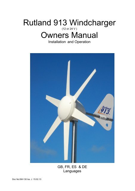
<strong>Rutland</strong> <strong>913</strong> <strong>Windcharger</strong><br />
Installation & Operation<br />
<strong>Rutland</strong> <strong>913</strong> <strong>Windcharger</strong><br />
(12 or 24 V )<br />
<strong>Owners</strong> <strong>Manual</strong><br />
Installation and Operation<br />
GB, FR, ES & DE<br />
Languages<br />
Doc No:SM-130 Iss. J 15.02.13 1 <strong>Marlec</strong> Eng <strong>Co</strong> Ltd
<strong>Rutland</strong> <strong>913</strong> <strong>Windcharger</strong><br />
Installation & Operation<br />
Doc No:SM-130 Iss. J 15.02.13 2 <strong>Marlec</strong> Eng <strong>Co</strong> Ltd
<strong>Rutland</strong> <strong>913</strong> <strong>Windcharger</strong><br />
Installation & Operation<br />
<strong>Co</strong>ntents<br />
Page:<br />
Introduction 4<br />
Summary of Features and Uses 4<br />
Profile and Dimensions 4<br />
General Guidelines and Warnings 5<br />
Check You Have Received 6<br />
Other Items 7<br />
Exploded View of the <strong>Rutland</strong> <strong>913</strong> 7<br />
Assembly & Installation<br />
Twelve Step Quick Start Guide 8<br />
Tower Preparation 9<br />
Blade Assembly 9<br />
Electrical <strong>Co</strong>nnection & Fitting to the Tower 10<br />
Up & Running<br />
Four Point Checklist 10<br />
Typical Wiring Diagrams for the <strong>Rutland</strong> <strong>913</strong> <strong>Windcharger</strong> 11<br />
Siting the <strong>Windcharger</strong><br />
General <strong>Co</strong>nsiderations 12<br />
Mounting The <strong>Windcharger</strong><br />
On Board Systems 13<br />
Land Based Systems 14<br />
Further System Requirements<br />
Batteries 15<br />
Cable Specifications 15<br />
Specification & Performance<br />
Guideline Performance Curve 16<br />
Maintenance & Troubleshooting<br />
Inspection & Maintenance 17<br />
Troubleshooting 18<br />
Installation Instructions (abbreviated) - French 20<br />
Installation Instructions (abbreviated) - Spanish 23<br />
Installation Instructions (abbreviated) - German 26<br />
For Your Records 29<br />
Doc No:SM-130 Iss. J 15.02.13 3 <strong>Marlec</strong> Eng <strong>Co</strong> Ltd
<strong>Rutland</strong> <strong>913</strong> <strong>Windcharger</strong><br />
Installation & Operation<br />
Introduction<br />
<strong>Co</strong>ngratulations and thank you for purchasing your <strong>Rutland</strong> <strong>913</strong> <strong>Windcharger</strong>.<br />
The utmost of care goes into the manufacture of all our products in our ISO9001<br />
approved factory. To ensure you get the very best out of the <strong>Rutland</strong> <strong>913</strong> we<br />
recommend that you read this manual and familiarise yourself with its contents<br />
before installing and operating the <strong>Windcharger</strong> system.<br />
Summary of Features and Uses<br />
Aerodynamically styled to maintain good wind flow and stability.<br />
Low wind speed start up maximises power generation in low winds.<br />
High grade construction materials for durability, U.V. stability and weather<br />
resistance.<br />
Provides a D.C. power supply to charge 12 or 24 V battery banks.<br />
Designed for use on board sailing yachts, motor caravans, static caravans<br />
and sites where low power is needed for domestic devices as well as<br />
navigation equipment etc.<br />
Note: There are other <strong>Rutland</strong> <strong>Windcharger</strong>s designed for permanent<br />
installations on land - contact <strong>Marlec</strong> or visit www.marlec.co.uk to find out<br />
more.<br />
<strong>Rutland</strong> <strong>913</strong> Profile & Dimensions<br />
Fig 1<br />
Doc No:SM-130 Iss. J 15.02.13 4 <strong>Marlec</strong> Eng <strong>Co</strong> Ltd
<strong>Rutland</strong> <strong>913</strong> <strong>Windcharger</strong><br />
Installation & Operation<br />
General Guidelines & Warnings<br />
Mounting pole outside diameter MUST NOT exceed 48.5mm for at least the<br />
top 0.5m. Larger section poles must not be used as this will reduce the tower<br />
to blade clearance. In high wind conditions this could cause damage to the<br />
<strong>Windcharger</strong> by allowing the blade to come into contact with the mounting<br />
pole. A broken blade will cause turbine imbalance with consequent damage.<br />
When turning, the <strong>Windcharger</strong> is capable of generating voltages in excess of<br />
the nominal voltage. The turbine must never be allowed to rotate unless it is<br />
electrically connected to a regulator or batteries. <strong>Co</strong>nnecting an open circuit<br />
running turbine to the electrical system can cause serious damage to system<br />
components owing to excessive voltage. Caution must be exercised at all<br />
times to avoid electric shock.<br />
Stopping the turbine – this may be necessary to undertake battery<br />
maintenance. If possible stopping the turbine should be done in low wind<br />
speed conditions. The turbine can be slowed by rotating or orienting the tail<br />
fin upwind, this will slow the turbine sufficiently for it to be safely secured to the<br />
pole with rope. Avoid leaving the turbine tied up for any period of time, we<br />
recommend that the turbine either be covered to give protection from the<br />
weather or removed and stored in a dry location. We recommend the use of<br />
<strong>Marlec</strong> charge regulator that includes a shutdown switch.<br />
Choose a calm day to install the equipment and consider other safety aspects.<br />
No attempt to repair the system should be made until the wind generator is<br />
restrained from turning.<br />
The <strong>Windcharger</strong> is fitted with ceramic magnets, which can be damaged by<br />
heavy handling. The main generator assembly should be treated with care<br />
during transit and assembly.<br />
High winds – in high winds the windcharger’s built-in thermostat may operate<br />
to prevent the generator overheating. In this mode the output will cease and<br />
the turbine will temporarily speed up until such time as the lower level<br />
temperature is reached and the generator is once again connected and<br />
charging. This may be seen to cycle in prolonged high winds particularly in<br />
high ambient temperatures. If safely accessible you may prefer to temporarily<br />
secure the turbine.<br />
It is essential to observe the correct polarity when connecting the <strong>Windcharger</strong><br />
and all other components into an electrical circuit. Reverse connection will<br />
damage the <strong>Windcharger</strong> and incorrect installation will invalidate the warranty<br />
Doc No:SM-130 Iss. J 15.02.13 5 <strong>Marlec</strong> Eng <strong>Co</strong> Ltd
<strong>Rutland</strong> <strong>913</strong> <strong>Windcharger</strong><br />
Installation & Operation<br />
<br />
The fuse supplied must be fitted to protect the system.<br />
The <strong>Rutland</strong> <strong>913</strong> <strong>Windcharger</strong> is suitable for sailing boats and some land<br />
based applications. When storm winds are forecast the turbine can be<br />
restrained to minimise wear and tear particularly when installed on land<br />
based applications where Furlmatic model windchargers are normally<br />
recommended. Note that where the manufacturer recommends a furling type<br />
windcharger should have been used the warranty is invalidated in cases of<br />
storm damage.<br />
If in doubt, refer to your dealer, a competent electrical engineer or the<br />
manufacturer.<br />
Check You Have Received - See <strong>Rutland</strong> <strong>913</strong> Exploded View<br />
24 x No. 10x25mm special self-tapping screws<br />
1 x fuse and fuse holder<br />
1 x main generator assembly<br />
6 x aerofoil blades<br />
1 x nose cone + 3 x nylon fixing screws<br />
1 x 6mm Allen key<br />
1 x 2-way terminal block<br />
2 x M10 buttoncap screws<br />
2 x shakeproof washers<br />
In the event of loss or damage, consult your dealer or the manufacturer.<br />
Doc No:SM-130 Iss. J 15.02.13 6 <strong>Marlec</strong> Eng <strong>Co</strong> Ltd
<strong>Rutland</strong> <strong>913</strong> <strong>Windcharger</strong><br />
Installation & Operation<br />
Other Items<br />
What You Will Need - Tools<br />
Suitable wire stripper<br />
Small terminal screwdriver<br />
Large flat blade screwdriver<br />
Crosshead screwdriver<br />
10mm Spanner or Socket<br />
Other Items You Will Need<br />
Mounting pole<br />
Cable<br />
Batteries<br />
Battery terminals<br />
<strong>Co</strong>nnector blocks (as<br />
determined by your total system)<br />
Other Items You May Have Selected<br />
HRSi, or HRDi Charge Regulator<br />
Cable (usually 2.5mm² twin core - Part No: 902-015)<br />
<strong>Rutland</strong> <strong>913</strong> Marine Mounting Kit and Stays Kit ( CA-12/02 & CA-12/32 )<br />
<strong>Rutland</strong> <strong>913</strong> Land Tower & Rigging Kit (Part Nos: CA-12/08 & CA-12/07)<br />
Short section of stainless steel tube to adapt into your own mounting design.<br />
Voltmeter & Ammeter<br />
Exploded View of The <strong>Rutland</strong> <strong>913</strong><br />
Nacelle Dome<br />
Six Blades with<br />
Twenty Four<br />
Screws<br />
Nose <strong>Co</strong>ne<br />
With Three<br />
Screws<br />
Post Adaptor<br />
Generator Hub<br />
Doc No:SM-130 Iss. J 15.02.13 7 <strong>Marlec</strong> Eng <strong>Co</strong> Ltd
<strong>Rutland</strong> <strong>913</strong> <strong>Windcharger</strong><br />
Installation & Operation<br />
Assembly and Installation<br />
Twelve Step Quick Start Guide<br />
1. Choose an open site to expose the <strong>Windcharger</strong> to a clear flow of wind and avoiding<br />
obstructions. On board mount the <strong>Windcharger</strong> at least 2.4 metres above the deck and<br />
on land at least 4 - 6 m high. Read the full section on Siting.<br />
2. Choose a mounting pole with an internal diameter of 41.0mm and external<br />
diameter of no greater than 48.5 mm for the top 0.6m minimum to (i) prevent<br />
accidental damage and (ii) meet warranty conditions.<br />
3. Mount a charge regulator, from the <strong>Marlec</strong> range, to a suitable vertical surface<br />
and close to the battery. Follow instructions supplied with the charge regulator.<br />
4. Drill the mounting pole, if required, in preparation to accept and secure the<br />
<strong>Windcharger</strong>. See Assembly and Installation section.<br />
5. Choose suitable two core cable to connect from the <strong>Windcharger</strong> to the regulator. Up<br />
to 20m this should be of at least 2.5mm² cross sectional area. A short section of 4mm²<br />
cross sectional area is required to link the regulator to the battery. For other distances<br />
see the table in Cable Specifications.<br />
6. Position the mounting pole ( this may be done on the ground before raising the<br />
pole ) so that the selected cable can be threaded along it.<br />
7. Fit the blades, tail and nose to the <strong>Windcharger</strong> using fasteners provided. It is<br />
essential that 4 screws are fitted per blade.<br />
8. Join the cable threaded through the pole to the <strong>Windcharger</strong> output cable using<br />
the connector block provided. Wrap with insulating tape. Alternatively use a<br />
latching plug and socket. We recommend looping back the cable and securing<br />
with a cable tie to provide strain relief to the joint.<br />
9. Carefully push the cables down the pole whilst sliding the post adaptor down<br />
the pole. Line up the holes and secure in place with the screws and washers<br />
provided. Tighten with the Allen key. Do not allow the turbine to spin freely.<br />
10.Locate the charge regulator close to the battery and carefully follow ALL the<br />
regulator guidelines and installation sequences for connecting the <strong>Windcharger</strong><br />
through to the battery. Note : Install the in-line fuse supplied with the<br />
<strong>Windcharger</strong> between the battery and charge regulator.<br />
11.Ensure that the battery connections are permanent as the <strong>Windcharger</strong> should<br />
NEVER be operated without a connection to the battery.<br />
12.Raise and secure the <strong>Windcharger</strong>. It can now be allowed to rotate. Follow the<br />
“ Up and Running- Four Points Final Checklist” featured later. Also the<br />
“ General Guidelines and Warnings” section expands on the above points.<br />
Doc No:SM-130 Iss. J 15.02.13 8 <strong>Marlec</strong> Eng <strong>Co</strong> Ltd
<strong>Rutland</strong> <strong>913</strong> <strong>Windcharger</strong><br />
Installation & Operation<br />
Assembly and Installation Detailed Instructions<br />
Fig.2<br />
Tower Preparation (Fig.2)<br />
1. Select a suitable pole from the suggested<br />
guidelines in Mounting the <strong>Windcharger</strong>.<br />
Note that the post adapter fitted to the <strong>913</strong><br />
is designed to fit inside a standard 41mm<br />
(1”) internal diameter tube.<br />
The adapter is provided with a flat on one<br />
side to clear the weld seam on seamed pipe.<br />
2. Mark and centre-punch two positions diametrically opposite, at 90° to the pipe<br />
seam if necessary, 20mm from top of the tube<br />
Note: Use metric measurements for this operation<br />
3. Drill two holes 10.5mm in diameter on centre-punch positions.<br />
Note :Use metric measurements for this operation<br />
Note: When using <strong>Rutland</strong> <strong>913</strong> Mounting Kit , items 2 and 3 can be ignored as<br />
<strong>Marlec</strong> supplied poles are pre-drilled.<br />
Fig. 3<br />
Blade Assembly (Fig.3)<br />
1. Place the generator assembly on a flat<br />
surface hub-side down. Position blade as<br />
shown. The blades will only fit one way<br />
around.<br />
2. Insert the protrusion at the trailing edge of<br />
the blade root fixing first into the socket to<br />
align with the corresponding recess in the<br />
blade socket. The blade can then be<br />
inserted with a lever action. A soft faced<br />
mallet may be used to tap the end of the<br />
blade to assist in fully locating the blade.<br />
3. First fit each blade with two special self-tapping screws provided to the rear of<br />
each blade by inserting each in turn through the cut out in the nacelle, rotating<br />
the generator each time until the holes align. Fit the remaining blade screws<br />
from the front of the generator hub. Check tightness of all screws but do not<br />
over-tighten. Caution- It is essential that all 4 screws are fitted!<br />
4. Fit the plastic nose dome in position on the front of the generator hub and<br />
secure in place with the three nylon screws provided.<br />
Alternatively the blades and nose dome can be fitted after mounting the generator<br />
assembly to the tower.<br />
Doc No:SM-130 Iss. J 15.02.13 9 <strong>Marlec</strong> Eng <strong>Co</strong> Ltd
<strong>Rutland</strong> <strong>913</strong> <strong>Windcharger</strong><br />
Installation & Operation<br />
Electrical <strong>Co</strong>nnection and Fitting to The Tower<br />
1. Run the cable selected (see Table 1) down the inside of the pole.<br />
2. Select one of the 2 basic wiring systems on page 12 and follow the manual<br />
provided with the voltage controller.<br />
3. <strong>Co</strong>nnect the wind generator flying leads to the cable protruding from the<br />
tower using the connector block supplied, taking care to observe polarity.<br />
<strong>Co</strong>nnect the <strong>Windcharger</strong> + to cable + and windcharger – to cable –<br />
Red is + Positive<br />
Black is - Negative<br />
4. Wrap the connection with insulation tape to secure/protect from environment.<br />
Alternatively join the cables using a latching-type plug and socket.<br />
5. Locate the wind generator into the tower whilst gently easing the cable from<br />
the tower base to ensure the cable is not trapped. Secure the wind generator<br />
to the tower using the button cap screws and shake proof washers provided,<br />
tighten using the 6mm Allen key provided.<br />
Up and Running<br />
Four Point Final Checklist<br />
Before raising and securing the wind generator:<br />
1. Check the tightness of the blade & tail fixing screws and generator mounting<br />
screws.<br />
2. Check free rotation of the hub and yaw axis.<br />
3. Check that the cable is not trapped.<br />
4. Check that all electrical connections are secure and safe.<br />
The wind generator can now be raised into position.<br />
Take care to avoid all moving parts when raising and lowering the wind<br />
generator.<br />
When raised, secure the structure firmly in an upright position.<br />
Caution-The performance of your <strong>Windcharger</strong> will be impaired if the pole is<br />
not vertical.<br />
Doc No:SM-130 Iss. J 15.02.13 10 <strong>Marlec</strong> Eng <strong>Co</strong> Ltd
<strong>Rutland</strong> <strong>913</strong> <strong>Windcharger</strong><br />
Installation & Operation<br />
Typical Wiring Diagrams For The <strong>Rutland</strong> <strong>913</strong> <strong>Windcharger</strong><br />
Typical Wiring Scheme For A Single Battery Bank<br />
Solar Panel<br />
Maximum<br />
160 Watts<br />
HRSi Charge<br />
Regulator<br />
12/24 V<br />
Typical Wiring Scheme For Single or Dual Battery Banks<br />
Solar Panel<br />
Maximum<br />
160 Watts<br />
HRDi Charge<br />
Regulator<br />
12/24 V<br />
In-Line Fuse<br />
Second battery<br />
optional<br />
Doc No:SM-130 Iss. J 15.02.13 11 <strong>Marlec</strong> Eng <strong>Co</strong> Ltd
<strong>Rutland</strong> <strong>913</strong> <strong>Windcharger</strong><br />
Installation & Operation<br />
Siting The <strong>Windcharger</strong><br />
General <strong>Co</strong>nsiderations<br />
The location and height of the mounting pole or tower for your wind turbine will<br />
be the major factor in the overall performance of your system. The smooth flow<br />
of wind over land and water is often interrupted by a multitude of<br />
obstructions causing wind sheer and turbulence.<br />
Wind shear describes the interference between the fast moving upper air and<br />
the slow moving air close to the ground and the resulting decrease in average<br />
wind speed as one gets closer to the ground.<br />
Turbulence is caused by the wind passing over obstructions such as moored<br />
boats, trees, and buildings.<br />
Both wind sheer and turbulence diminish with height and can be overcome<br />
simply by putting the turbine sufficiently high above them as shown in Fig 4.<br />
Windspeed decreases and turbulence increases where obstructions exist.<br />
<strong>Co</strong>nsider also that downwind obstructions can be as detrimental to performance<br />
as upwind obstructions.<br />
It is therefore essential that the wind generator should be located in an area as<br />
free as possible from disturbed wind flow.<br />
Fig. 4<br />
WIND DIRECTION<br />
AREA OF TURBULENCE<br />
H<br />
2H<br />
2H<br />
20H<br />
Doc No:SM-130 Iss. J 15.02.13 12 <strong>Marlec</strong> Eng <strong>Co</strong> Ltd
<strong>Rutland</strong> <strong>913</strong> <strong>Windcharger</strong><br />
Installation & Operation<br />
Mounting The <strong>Windcharger</strong><br />
Fig. 5<br />
Fig. 6<br />
On Board Systems<br />
The wind generator should be mounted in a safe<br />
position, a minimum of 2.3 metres (7.6 feet) above<br />
the deck and away from other obstacles which<br />
could interfere with the blades or tail assembly<br />
(Fig. 5).<br />
The <strong>Rutland</strong> <strong>913</strong> Mounting & Stays Kits (Part No.<br />
CA-12/02 & CA-12/32) are available for deck<br />
mounting, or short sections of stainless steel tube<br />
of 1200mm (47”) and 600mm (23”) pre-drilled are<br />
also available for your own fabrication.<br />
The <strong>Rutland</strong> <strong>913</strong> is designed to fit inside an<br />
aluminium or stainless steel tube with an internal<br />
diameter of 41mm (1”). IMPORTANT: The<br />
external diameter MUST NOT exceed 48.5mm<br />
(1), see Warning in Introduction.<br />
Suitable tubes: Stainless Steel 1 3 / 4 ”16 SWG and<br />
Aluminium 1 7 / 8 ” 10 SWG<br />
Fig. 7<br />
We suggest the following mountings according to<br />
preference and site conditions:-<br />
Push pit (Fig.6)<br />
A suitable pole mounted to the deck with deck<br />
plates and solid guys is the most popular method of<br />
mounting the <strong>Windcharger</strong> on yachts, eg. <strong>Rutland</strong><br />
<strong>913</strong> Mounting & Stays Kit.<br />
Fig. 8<br />
Mizzen (Fig.7)<br />
Mizzen mounting is suitable on larger yachts,<br />
taking advantage of greater wind flow the higher<br />
the wind turbine is mounted.<br />
River Boats (Fig.8)<br />
A pivot pole is ideal for riverboats as the<br />
<strong>Windcharger</strong> can easily be raised and lowered.<br />
Doc No:SM-130 Iss. J 15.02.13 13 <strong>Marlec</strong> Eng <strong>Co</strong> Ltd
<strong>Rutland</strong> <strong>913</strong> <strong>Windcharger</strong><br />
Installation & Operation<br />
Fig. 9<br />
Centre pivoted pole<br />
Fig. 10<br />
Base pivoted with gin pole<br />
Land Based Systems<br />
The <strong>Rutland</strong> <strong>913</strong> is suitable for some land based<br />
temporary and leisure applications. The Furlmatic<br />
<strong>Windcharger</strong> model is recommended for land<br />
based remote and exposed locations.<br />
The <strong>Rutland</strong> <strong>913</strong> is designed to fit inside<br />
aluminium, stainless or steel tube with an internal<br />
diameter of 41mm. (1”). IMPORTANT: The<br />
external diameter MUST NOT exceed 48.5mm<br />
(1), see Warning in Introduction.<br />
A suitable mounting pole can be erected using a<br />
6.5 metre (21 feet) galvanised (medium) tube.<br />
The tube must be supported by a minimum of four<br />
guy lines. The attachment points for the guy lines<br />
to the tower should be securely fixed to the tower.<br />
The guy wires should be a minimum of 4mm<br />
(0.16”) in diameter.<br />
The shackles should be a minimum of 5mm<br />
(0.20”) in diameter.<br />
Rigging screws should be a minimum of 5mm<br />
(0.20”) in diameter.<br />
All items should be galvanised or stainless<br />
steel for protection against corrosion.<br />
Where guy lines are looped, the loop must<br />
incorporate a thimble and be fitted with a<br />
minimum of three rope grips.<br />
All ground fixings must be made suitable<br />
according to the terrain.<br />
We suggest pivot type towers as these allow for<br />
easier installation and lowering for access to the<br />
wind generator. Two forms of pivot tower are<br />
suggested in Figs 9 & 10.<br />
A base-hinged 6.4m tall Land Tower Kit (Part<br />
No: CA-12/08) and Rigging Kit (Part No:<br />
CA-12/07) are available from <strong>Marlec</strong>.<br />
Doc No:SM-130 Iss. J 15.02.13 14 <strong>Marlec</strong> Eng <strong>Co</strong> Ltd
<strong>Rutland</strong> <strong>913</strong> <strong>Windcharger</strong><br />
Installation & Operation<br />
Further System Requirements<br />
Total = 12v<br />
120Ah<br />
1440Wh<br />
60Ah<br />
12v<br />
60Ah<br />
12v<br />
In parallel to increase amp<br />
Total = 24v<br />
60Ah<br />
1440Wh<br />
60Ah<br />
12v<br />
60Ah<br />
12v<br />
In series to increase voltage<br />
Batteries<br />
Leisure/Deep Cycle batteries are specifically<br />
designed for good performance in terms of<br />
charge/discharge cycles. Batteries are the<br />
most important part of your battery charging<br />
system and should be sized according to your<br />
load requirements and provide at least 3 days<br />
reserve capacity. This will reduce cycling,<br />
prolong the life of the battery and ensure<br />
system reliability during periods of low wind.<br />
Permanent connections should always be made<br />
to the battery terminals. Never use crocodile<br />
clips or similar devices.<br />
We strongly recommend that one of the voltage<br />
regulators available from <strong>Marlec</strong> is fitted to<br />
prevent batteries becoming overcharged in<br />
strong winds and is essential with gel/sealed<br />
batteries.<br />
Batteries may be linked as shown in the figures<br />
10 and 11. It is essential to observe polarity as<br />
follows:<br />
Red is + Positive<br />
Black is - Negative<br />
Cable Specification<br />
Cable<br />
Run<br />
(m)<br />
12V<br />
Cable Size<br />
24V<br />
mm² AWG mm² AWG<br />
0-20 2.5 13 1.5 15<br />
21-30 4 11 2.5 13<br />
31-45 6 9 4 11<br />
46-80 10 7 6 9<br />
The cable used for connection of the<br />
<strong>Windcharger</strong> to the batteries should be in<br />
accordance with table 1. The use of a<br />
smaller cable than recommended will<br />
reduce the performance of the charging<br />
system.<br />
Cable and connectors are available from<br />
your dealer or the manufacturer.<br />
Doc No:SM-130 Iss. J 15.02.13 15 <strong>Marlec</strong> Eng <strong>Co</strong> Ltd
<strong>Rutland</strong> <strong>913</strong> <strong>Windcharger</strong><br />
Installation & Operation<br />
Specification and Performance<br />
Guideline Performance Curve<br />
Note : The curve shown below is for clear, non-turbulent wind conditions; this<br />
may not be achieved in some installations. Refer to the section on Siting to<br />
optimise performance at your site. Wind speeds are those flowing across the<br />
turbine of the <strong>Windcharger</strong> and may not reflect those measured at mast top or<br />
those reported by the Met. Office.<br />
20<br />
10<br />
18<br />
9<br />
16<br />
WINDSPEED CONVERSION<br />
8<br />
Charge into 12 V Battery (Amperes)<br />
14<br />
12<br />
10<br />
8<br />
6<br />
4<br />
2<br />
0<br />
MPH = Knots x 1.15<br />
M/S = Knots x .515<br />
7<br />
6<br />
5<br />
4<br />
3<br />
2<br />
1<br />
0<br />
Charge into 24 V Battery (Amperes)<br />
0 5 10 15 20 25 30 35 40<br />
Windspeed (Knots)<br />
Doc No:SM-130 Iss. J 15.02.13 16 <strong>Marlec</strong> Eng <strong>Co</strong> Ltd
<strong>Rutland</strong> <strong>913</strong> <strong>Windcharger</strong><br />
Installation & Operation<br />
Maintenance and Troubleshooting<br />
Inspection and Maintenance<br />
The <strong>Rutland</strong> <strong>913</strong> requires no scheduled maintenance but an annual inspection<br />
should be carried out to monitor the general condition of the system to ensure<br />
the electrical and mechanical integrity and safety of the system.<br />
WARNING! Before inspection, the turbine should either be lowered to the<br />
ground or tied to prevent the generator from turning. To stop the generator from<br />
turning proceed as follows:<br />
1. Either rotate the switch to stall mode on the charge regulator if used OR turn<br />
the wind generator out of the wind (180°) using the tail, a hole is<br />
provided in the tail fin to assist in this. The generator will gradually slow down.<br />
2. Tie a blade to the mounting pole to prevent it from rotating.<br />
Whilst the generator is stationary, the following routine checks should be<br />
performed:<br />
1. Check the blades for damage, eg chips or nicks. Replace any damaged<br />
blades. The turbine should not be operated with damaged blades as this may<br />
cause imbalance resulting in premature wear and possible failure. Check the<br />
blade screws for tightness.<br />
2. Check all other nuts, bolts and screws for tightness.<br />
3. Check the yaw axis for free rotation.<br />
4. Check tower assembly for condition.<br />
5. Check the tension of the guy wires if applicable. The tension of guy wires<br />
should be checked frequently during the first year.<br />
6. The unit can be wiped with a mild detergent and rinsed with water to remove<br />
dirt and debris.<br />
Note: The <strong>Windcharger</strong> is designed for continuous running to achieve<br />
maximum resistance to water ingress. Should you wish to take the<br />
unit out of service for an extended period it is recommend that the<br />
unit be removed from the mounting and stored in a dry location or<br />
covered.<br />
Doc No:SM-130 Iss. J 15.02.13 17 <strong>Marlec</strong> Eng <strong>Co</strong> Ltd
<strong>Rutland</strong> <strong>913</strong> <strong>Windcharger</strong><br />
Installation & Operation<br />
Troubleshooting<br />
In the unlikely event that your <strong>Rutland</strong> <strong>913</strong> should develop a defect, the turbine<br />
should first be tied to prevent the blades from turning to perform the static tests<br />
below. (Follow the procedure described in the Inspection and Maintenance<br />
section) It will be necessary to let it run for the tests to check for power<br />
production.<br />
Read the Electrical <strong>Co</strong>nnection and Up and Running sections and b satisfied<br />
that your system complies.<br />
Is there sufficient wind The <strong>Rutland</strong> <strong>913</strong> needs 5 knots wind speed to start<br />
charging. The wind speed across the turbine blades may be greatly reduced in a<br />
marina or built-up area compared with the reading on a masthead anemometer<br />
or weather reports.<br />
Static Tests:<br />
Is the battery in good condition Check the voltage and electrolyte level of<br />
each battery.<br />
Check electrical continuity throughout the system, especially corrosion and<br />
poor connections in cable joins and connector blocks.<br />
Running Tests:<br />
Check for power output from the windcharger, following this procedure:<br />
1. Set a digital multimeter to DC Amps, scale of between 5 and 10 if possible.<br />
<strong>Co</strong>nnect the meter positive (+) probe to the wind generator output positive<br />
cable and the meter negative (-) to the regulator input positive. Provided<br />
there is sufficient wind there should be a current reading. This establishes<br />
that power is being delivered.<br />
2. Using the same multimeter setting as above measure between the regulator to<br />
battery + and the battery +. Provided there is sufficient wind there should be a<br />
current reading. This establishes if power is passing through the regulator.<br />
3. If both above are unsuccessful set the multimeter to DC Volts. Disconnect the<br />
wind generator from the regulator and connect the meter + to the wind<br />
generator + and the meter – to the wind generator -. Provided there is<br />
sufficient wind there should be a variable voltage reading according to the<br />
speed of the wind seen at the wind turbine. This will establish if the wind<br />
generator is able to deliver power or not.<br />
4. If tests 1 and 3 are successful but test 2 fails to produce results connect the<br />
wind generator directly to the battery. Set the digital multimeter to DC Amps<br />
and measure power between the wind generator + and the battery +. If a<br />
reading is measured, providing there is sufficient wind, then the regulator is<br />
faulty.<br />
5. If the wind turbine fails to deliver any current or open circuit V reading<br />
undertake the further tests below.<br />
Doc No:SM-130 Iss. J 15.02.13 18 <strong>Marlec</strong> Eng <strong>Co</strong> Ltd
<strong>Rutland</strong> <strong>913</strong> <strong>Windcharger</strong><br />
Installation & Operation<br />
6. Mechanical inspection. It may be necessary to remove the windcharger from<br />
its pole for the following tests.<br />
Check the brushes and slipring for wear or damage. To inspect the brushes,<br />
remove the nacelle by removing the three fixing screws and slide the nacelle<br />
backwards towards the tail fin. The brushes and slipring can be inspected by<br />
removing the four self-tapping screws holding the brush holder assembly in<br />
place. Remove any black deposits from slipring with emery paper. Heavy<br />
deposits and reduced power indicate a possible reverse connection to the<br />
battery (see Page 10).<br />
Check hub for free rotation with generator disconnected from battery.<br />
If the hub does not rotate freely, check for a possible short circuit in the wiring.<br />
If no wiring fault is found refer to your dealer or manufacturer.<br />
If the above checks have identified a need for spare parts or failed to identify the<br />
problem you should contact your dealer. Visit www.marlec.co.uk for further fault<br />
finding guides and support.<br />
If in doubt, refer to your dealer or manufacturer.<br />
Doc No:SM-130 Iss. J 15.02.13 19 <strong>Marlec</strong> Eng <strong>Co</strong> Ltd
<strong>Rutland</strong> <strong>913</strong> <strong>Windcharger</strong><br />
Installation & Operation<br />
Introduction<br />
Francais<br />
Félicitations pour votre achat d’une éolienne <strong>Rutland</strong> <strong>913</strong> ! <strong>Co</strong>mme tous nos produits, elle a été<br />
fabriquée avec le plus grand soin, dans notre usine certifiée ISO 9001. Pour obtenir pleine<br />
satisfaction de votre éolienne <strong>Rutland</strong> <strong>913</strong>, nous vous recommandons de lire entièrement ce<br />
manuel et de vous familiariser avec son contenu avant de commencer l’installation ou de l’utiliser.<br />
Principales caractéristiques et applications<br />
<strong>Co</strong>nception aérodynamique pour une bonne prise au vent.<br />
Tourne avec peu de vent pour optimiser les performances même par vent faible.<br />
Matériaux de qualité pour une durée de vie optimale, une bonne résistance aux UV et aux<br />
conditions climatiques.<br />
Permet de charger des batteries 12V ou 24V.<br />
<strong>Co</strong>nçue pour fonctionner sur des bateaux, des camping-cars, des mobil-homes ou sur des sites<br />
où une faible puissance est nécessaire pour faire fonctionner des appareils ménagers, de<br />
l’instrumentation, etc.NB : il existe d’autres modèles d’éoliennes conçues pour une installation<br />
terrestre permanente. Venez les découvrir sur notre site www.marlec.co.uk<br />
Informations générales et mises en garde<br />
Le diamètre externe du mât ne doit pas être supérieur à 48,5mm, au moins sur les 50 derniers<br />
centimètres. Ne pas utiliser de mât plus gros au risque de réduire le jeu nécessaire entre les<br />
pales et le mât. En cas de vents forts, les pales risquent de heurter le mât et de s’endommager.<br />
Une pale brisée provoque un déséquilibre capable d’entraîner des dégâts importants.<br />
Lorsqu’elle fonctionne, l'éolienne peu générer de l'électricité à haute tension, c’est pourquoi elle<br />
ne doit pas tourner tant qu’elle n’est pas reliée à un régulateur ou à des batteries. Raccorder<br />
directement l’éolienne à l’installation électrique peut provoquer des dégâts importants en raison<br />
de la surtension. Pour éviter tout risque d’électrochoc, vous devez être constamment vigilant.<br />
Stopper l’éolienne – Cela peut s’avérer nécessaire avant d’intervenir sur les batteries. Dans la<br />
mesure du possible, il est préférable de le faire lorsque le vent est faible. L’éolienne peut alors<br />
être ralentie en orientant l’aileron contre le vent ce qui permet de l’immobiliser en l’attachant au<br />
mât avec une corde. Éviter de l’immobiliser trop longtemps. Il est recommandé de la couvrir<br />
pour la protéger des effets du climat ou de la déposer pour l’entreposer en lieu sec. Les<br />
régulateurs HRSi et HRDi sont équipé d’un interrupteur Marche/Arrêt.<br />
Entres autres éléments de sécurité, effectuer l’installation par temps calme.<br />
Aucune tentative de réparation ne doit être engagée tant que l'éolienne n'est pas immobilisée.<br />
L'éolienne est équipée d'aimants céramiques qui peuvent facilement être abîmés lors de leur<br />
manipulation. Elle doit être maniée avec précaution durant le transport et le montage.<br />
Vents forts – Par vents forts, la sécurité thermique intégrée peut stopper l’éolienne pour<br />
l’empêcher de surchauffer. Dans ce cas, l’éolienne ne produit plus d’électricité et sa vitesse de<br />
rotation peut augmenter, le temps nécessaire au refroidissement. Elle se remet automatiquement<br />
en marche lorsque la température a baissé. Si les vents forts persistent et plus particulièrement<br />
par temps chaud, vous verrez ces cycles se répéter. S’il vous est possible d’accéder à<br />
l’éolienne en toute sécurité, il est préférable de la bloquer temporairement.<br />
Doc No:SM-130 Iss. J 15.02.13 20 <strong>Marlec</strong> Eng <strong>Co</strong> Ltd
<strong>Rutland</strong> <strong>913</strong> <strong>Windcharger</strong><br />
Installation & Operation<br />
Il est essentiel de respecter les polarités lors du branchement de l'éolienne<br />
ainsi que de tous les autres composants du système électrique. Inverser les<br />
branchements endommagerait l'éolienne et une installation incorrecte<br />
annulerait la garantie.<br />
Le fusible fourni doit être installé pour protéger l'appareil.<br />
L’éolienne <strong>Rutland</strong> <strong>913</strong> est conçue pour une utilisation sur des bateaux à voiles<br />
ou certaines applications terrestres. Lorsque des vents d’orage sont annoncés,<br />
l’éolienne peut être immobilisée pour prévenir les risques d’usure et de casse,<br />
notamment lorsqu’elle est installée sur un site terrestre exposé aux vents forts<br />
pour lesquels il est recommandé d’utiliser des modèles Furlmatic (avec mise en<br />
drapeau automatique). Si ce type d’éolienne est recommandé par le<br />
constructeur pour une application, mais qu’il n’en est pas tenu compte, la<br />
garantie ne fonctionnera en cas de dommages occasionnés par des vents forts.<br />
En cas de doute, se référer à votre revendeur, à un ingénieur compétent en<br />
électricité ou au fabricant.<br />
6 x Pâles et<br />
24 x Vis 10 x 25mm<br />
autotaraudeuses<br />
1 x Nacelle<br />
1 x Adapteur de<br />
poteau<br />
1 x <strong>Co</strong>rps<br />
d’éolienne<br />
1 x Cône avant +<br />
3 vis de fixation<br />
Doc No:SM-130 Iss. J 15.02.13 21 <strong>Marlec</strong> Eng <strong>Co</strong> Ltd
<strong>Rutland</strong> <strong>913</strong> <strong>Windcharger</strong><br />
Installation & Operation<br />
Guide d’installation en douze étape<br />
1. Choisir un emplacement dégagé pour que l’éolienne soit exposée au vent sans aucune<br />
obstruction. A bord d’un bateau, la monter au minimum 2,5 m au-dessus du pont et sur terre à<br />
une hauteur de 4 à 6 m minimum. Lire le chapitre « Choix de l’emplacement ».<br />
2. Prévoir un mât de 41 mm de diamètre intérieur et de 48,5 mm maximum de diamètre extérieur,<br />
au moins sur les 50 derniers centimètres, pour prévenir tout risque de dégâts et effectuer un<br />
montage conforme aux exigences de la garantie.<br />
3. Monter un régulateur, choisi dans la gamme proposée par <strong>Marlec</strong>, sur un plan vertical et à<br />
proximité des batteries. Suivre les instructions de montage fournies avec le régulateur.<br />
4. Le cas échéant, percer les trous de fixation sur le mât et fixer l’éolienne au mât. Voir le<br />
chapitre « Assemblage et installation de l’éolienne ».<br />
5. Choisir un câble adéquat à deux conducteurs pour relier l’éolienne au régulateur. Jusqu’à<br />
20 m de longueur, choisir un câble d’une section de 2,5 mm². Pour relier le régulateur à la<br />
batterie, un câble de 4 mm² est nécessaire. Pour d’autres longueurs, se reporter au chapitre<br />
« Type de câble ».<br />
6. Passer le câble dans le mât (cela peut se faire au sol, avant de dresser le mât).<br />
7. Fixer les pâles, l’aileron et le cône avant sur l’éolienne, à l’aide des fixations fournies. Chaque<br />
pâle doit être montée avec les quatre vis fournies.<br />
8. Utiliser le bloc de connexion fourni pour raccorder le câble passé dans le mât au câble sur<br />
l’éolienne. Protéger la connexion avec du ruban isolant. Vous pouvez aussi utiliser une prise<br />
Nous recommandons d’effectuer une boucle et de la fixer afin de diminuer la contrainte sur la<br />
connexion.<br />
9. Pousser les câbles à l’intérieur du mât avec précaution, et poser l’adaptateur dans le mât.<br />
Aligner les trous de fixation et sécuriser le montage avec les rondelles et les vis fournies.<br />
Serrer en utilisant la clé Allen également fournie. Empêcher la turbine de tourner à vide.<br />
10. Monter le régulateur à proximité de la batterie et suivre rigoureusement toutes les instructions<br />
ainsi que la séquence de branchements pour raccorder l’éolienne aux batteries. NB : monter<br />
en ligne le fusible fourni avec l’éolienne entre le régulateur et la batterie.<br />
11. L’éolienne ne doit en aucun cas pouvoir fonctionner sans être raccordée à la batterie,<br />
s’assurer que la connexion soit permanente.<br />
12. Dresser et fixer le mât. L’éolienne est maintenant prête à fonctionner. Effectuer les vérifications<br />
(en quatre points) indiquées au chapitre « Dressage et mise en service de l’éolienne ».<br />
Les « Informations générales et mises en garde » énoncées ci-dessus doivent également avoir<br />
été intégrées.<br />
Doc No:SM-130 Iss. J 15.02.13 22 <strong>Marlec</strong> Eng <strong>Co</strong> Ltd
<strong>Rutland</strong> <strong>913</strong> <strong>Windcharger</strong><br />
Installation & Operation<br />
Introducción<br />
Espanol<br />
Felicitaciones y gracias por comprar un cargador eólico <strong>Rutland</strong> <strong>913</strong>.<br />
Utilizamos sumo cuidado en la fabricación de todos nuestros productos en nuestra fábrica<br />
aprobada por la Norma ISO9001. Para asegurarnos de que reciba lo mejor de nuestro <strong>Rutland</strong><br />
<strong>913</strong>, le recomendamos que lea este manual y se familiarice con su contenido antes de instalar y<br />
poner en funcionamiento el sistema del cargador eólico.<br />
Resumen de características y usos<br />
estilo aerodinámico para mantener estabilidad y un buen flujo del viento<br />
el arranque con vientos a baja velocidad maximiza la producción de energía en vientos de<br />
poca fuerza<br />
materiales de construcción de gran calidad para mayor durabilidad, estabilidad U.V y<br />
resistencia a la intemperie<br />
proporciona una fuente de alimentación CC para cargar bancos de batería de 12 o 24 voltios.<br />
diseñado para ser utilizado a bordo de yates a vela, casillas rodantes motorizadas, casillas<br />
rodantes estáticas y sitios en donde se necesita una baja potencia para dispositivos<br />
domésticos como así también equipos de navegación, etc.<br />
Nota: Existen otros cargadores eólicos <strong>Rutland</strong> diseñados para instalaciones permanentes en<br />
tierra, para obtener mayor información, comuníquese con <strong>Marlec</strong> o visite la página Web<br />
www.marlec.co.uk.<br />
Pautas y advertencias generales<br />
El diámetro externo del mástil de montaje NO DEBE exceder los 48,5 mm aunque sea en los<br />
0,5m superiores. No utilice mástiles más grandes ya que esto reducirá el espacio entre la<br />
torre y la paleta. En condiciones de vientos fuertes, esto puedo provocar daños al cargador<br />
eólico ya que la paleta entra en contacto con el mástil de montaje. Una paleta rota producirá<br />
un desequilibrio en la turbina y daños posteriores.<br />
Al girar, el cargador eólico es capaz de generar voltajes superiores al voltaje nominal. Nunca<br />
permita que la turbina gire a menos que se encuentre conectada eléctricamente a un<br />
regulador o a una batería. La conexión de una turbina que funciona con un circuito abierto al<br />
sistema eléctrico puede provocar daños graves a los componentes del sistema por el<br />
excesivo voltaje. En todo momento, tenga cuidado y evite las descargas eléctricas.<br />
Detención de la turbina: puede ser necesaria para realizar el mantenimiento de la batería. Si<br />
es posible, detenga la turbina en condiciones de viento a baja velocidad. Disminuya la<br />
velocidad de la turbina girando o dirigiendo la aleta de la cola contra el viento; esto diminuirá<br />
la velocidad de la turbina lo suficiente como para que ésta se pueda sujetar con una soga y<br />
sin peligro al mástil. Evite dejar la turbina atada durante mucho tiempo; le recomendamos que<br />
cubra la turbina para protegerla de la intemperie o retírela y guárdela en un lugar seco. Le<br />
recomendamos que utilice el regulador de carga <strong>Marlec</strong> que incluye un interruptor de<br />
desconexión.<br />
Elija un día sin viento para instalar el equipo y tenga en cuenta otros aspectos de seguridad.<br />
No intente reparar el sistema hasta que el generador de viento este sujeto y no pueda girar.<br />
El cargador eólico esta ajustado con imanes cerámicos que pueden dañarse durante una<br />
fuerte manipulación. Tenga cuidado con el ensamblaje del generador principal durante el<br />
transporte y el montaje.<br />
Doc No:SM-130 Iss. J 15.02.13 23 <strong>Marlec</strong> Eng <strong>Co</strong> Ltd
<strong>Rutland</strong> <strong>913</strong> <strong>Windcharger</strong><br />
Installation & Operation<br />
Vientos fuertes: durante vientos fuertes el termostato incorporado al cargador eólico<br />
puede ponerse en funcionamiento para evitar que el generador se recaliente. En<br />
este modo, la salida se detendrá y la turbina se acelerará temporariamente hasta<br />
alcanzar una temperatura menor y el generador se encuentre nuevamente<br />
conectado y cargando. Se lo puede ver girar durante prolongados vientos fuertes,<br />
particularmente en temperaturas ambientales elevadas. Si es accesible y seguro,<br />
quizás prefiera sujetar temporariamente la turbina.<br />
Es esencial respetar la polaridad correcta al conectar el cargador eólico y todos los<br />
demás componentes en un circuito eléctrico. Una conexión inversa dañará al<br />
cargador eólico y la instalación incorrecta anulará la garantía.<br />
Ajuste el fusible incluido para proteger el sistema.<br />
El cargador <strong>Rutland</strong> <strong>913</strong> es apropiado para barcos de vela y algunas aplicaciones<br />
terrestres. Cuando se pronostica una tormenta de viento, se puede sujetar la<br />
turbina para minimizar el desgaste y daño particularmente cuando se encuentra<br />
instalada en aplicaciones terrestres en donde normalmente se recomiendan los<br />
modelos de cargadores eólicos Furlmatic. Tenga en cuenta que cuando el<br />
fabricante recomienda un cargador eólico plegable, la garantía se anulará en casos<br />
de daños por tormenta.<br />
6 x paletas y<br />
24 x 10x25<br />
torniillos<br />
1 x Cubierta<br />
1 x Adaptador del<br />
poste<br />
1 x Eje del generador<br />
1 x <strong>Co</strong>no de nariz y 3 x tornillos<br />
Doc No:SM-130 Iss. J 15.02.13 24 <strong>Marlec</strong> Eng <strong>Co</strong> Ltd
<strong>Rutland</strong> <strong>913</strong> <strong>Windcharger</strong><br />
Installation & Operation<br />
Guía rápida de inicio – 12 pasos<br />
1. Elija un sitio abierto para exponer al cargador eólico a un flujo libre de viento y así evitar<br />
obstrucciones. A bordo, monte el cargador eólico por lo menos a 2,4 metros de la cubierta,<br />
en tierra por lo menos a 4 hasta 6 metros de altura. Lea toda la sección de Instalación.<br />
2. Elija un mástil de montaje con un diámetro interno de 41 mm y un diámetro externo no mayor<br />
a 48,5 mm para los primeros 0,6 mm cómo mínimo para (i) evitar daños accidentales y (ii)<br />
cumplir con las condiciones de la garantía.<br />
3. Monte un regulador de carga, del rango <strong>Marlec</strong>, sobre una superficie vertical adecuada y<br />
cerca de la batería. Siga las instrucciones proporcionadas con el regulador de carga.<br />
4. Perfore el mástil de montaje, en caso de ser necesario, para prepararlo para que tolere y<br />
sujete al cargador eólico. Vea la sección Montaje e Instalación.<br />
5. Elija un cable de dos conductores adecuado para que el cargador eólico se conecte con el<br />
regulador. De hasta 20 m, éste debería ser un área de secciones de por lo menos 2,5 mm²<br />
Es necesaria una pequeña área de sección de 4 mm² para unir el regulador a la batería.<br />
Para consultar otras distancias, vea la clasificación en Especificaciones para cables.<br />
6. <strong>Co</strong>loque el mástil de montaje ( esto puede hacerlo en el piso antes de levantar el mástil) de<br />
tal manera que el cable seleccionado pueda enroscarse a lo largo del mismo.<br />
7. Ajuste las paletas, la cola y la nariz del cargador eólico mediante los fijadores<br />
proporcionados. Es esencial que ajuste 4 tornillos por paleta.<br />
8. Una el cable enroscado en el mástil al cable de salida del cargador eólico mediante el bloque<br />
conector proporcionado. Envuelva con cinta aisladora. O bien utilice un tapón o toma<br />
corriente con pestillo. Le recomendamos enroscar el cable y asegurarlo con una cinta de<br />
sujeción para cables para aliviar la tensión en la junta<br />
9. <strong>Co</strong>n cuidado presione los cables hacia el mástil mientras desliza el adaptador del mástil por<br />
el mismo. Alinee los orificios y sujételos en el lugar con los tornillos y arandelas<br />
proporcionadas. Apriete con la llave Allen. No permita que la turbina gire libremente.<br />
10. Ubique el regulador de carga cerca de la batería y siga cuidadosamente TODAS las pautas<br />
y secuencias de instalación del regulador para conectar el cargador eólico a la batería.<br />
Nota: instale el fusible en línea proporcionado con el cargador eólico entre la batería y el<br />
regulador de carga.<br />
11. Asegúrese de que las conexiones de la batería sean permanentes ya que el cargador<br />
eólico NUNCA debe ponerse en funcionamiento sin estar conectado a la batería.<br />
12. Levante y sujete el cargador eólico. Ahora puede dejarlo que gire. Siga la “Lista de control<br />
final de 4 puntos denominada: Instalado y en Funcionamiento”, que se observa más<br />
adelante. También la sección “Pautas y advertencias generales” amplía sobre los puntos<br />
mencionados.<br />
Doc No:SM-130 Iss. J 15.02.13 25 <strong>Marlec</strong> Eng <strong>Co</strong> Ltd
<strong>Rutland</strong> <strong>913</strong> <strong>Windcharger</strong><br />
Installation & Operation<br />
Einleitung<br />
Deutsche<br />
Wir gratulieren und bedanken uns für den Erwerb Ihres <strong>Rutland</strong> <strong>913</strong> <strong>Windcharger</strong>s. Wir leisten die<br />
beste Sorgfalt bei der Herstellung von allen unseren Geräten gemäß dem anerkannten<br />
Betriebsstandard ISO9001. Zur Gewährleistung für alle Vorteile beim Gebrauch von <strong>Rutland</strong> <strong>913</strong><br />
bitten wir Sie diese Anleitung vollständig durchzulesen, bevor Sie mit der Montage und<br />
Inbetriebnahme des <strong>Windcharger</strong>s fortfahren.<br />
Zusammenfassung der Funktionen und Anwendungen<br />
Aerodynamisch gestaltet für einen ausgezeichneten Luftstrom mit Luftstabilität.<br />
Das Anlassen bei einer niedrigen Windgeschwindigkeit maximiert Stromerzeugung bei geringen<br />
Windstärken.<br />
Hochwertige Baustoffe für Strapazierfähigkeit, UV-Strahlungsstabilität und<br />
Witterungsbeständigkeit.<br />
Ein Gleichstromnetzgerät zum Aufladen eines 12 oder 24 V Batteriesatzes wurde mitgeliefert.<br />
Für die Nutzung auf Segeljachten an Bord, bei Reisemobilen, Wohnmobilen und für Standorte<br />
bestimmt, wobei ein geringer Stromverbrauch für Haushaltsgeräte und auch für<br />
Navigationsgeräte etc. erforderlich ist.<br />
Anmerkung: Für weitere <strong>Windcharger</strong> von <strong>Rutland</strong>, welche für die dauerhafte Montage an Ort<br />
und Stelle entworfen wurden, treten Sie bitte mit <strong>Marlec</strong> in Kontakt oder besuchen Sie<br />
www.marlec.co.uk für weitere Informationen.<br />
Allgemeine Richtlinien & Gefahrenhinweise<br />
Die Mastmontage DARF den Außendurchmesser von 48.5mm, zumindest den Oberen von<br />
0.5m NICHT überschreiten. Größere Mastquerschnitte dürfen nicht verwendet werden, da dies<br />
zu einer geringeren Distanz zwischen dem Mast und dem Rotorblattspiels führt. Bei hohen<br />
Windbedingungen könnte es beim <strong>Windcharger</strong> zu Schaden führen, da das Rotorblatt mit dem<br />
festmontierten Mast in Kontakt kommen könnte. Ein zerbrochenes Rotorblatt verursacht ein<br />
Ungleichgewicht der Turbine und dementsprechend Schäden.<br />
Bei der Drehbewegung ist der <strong>Windcharger</strong> in der Lage Stromspannungen höher als die<br />
Nennspannung zu erzeugen. Es darf nie zugelassen werden, dass die Turbine rotiert, es sei<br />
denn das sie elektrisch mit einem Aufladekontrollgerät oder mit Batterien angeschlossen ist.<br />
Der Anschluss einer laufenden Turbine im Leerlauf an das Elektrosystem kann ernsthafte<br />
Schäden bei den Anlagebestandteilen, aufgrund der überhöhten elektrischen Spannung<br />
hervorrufen. Vorsicht ist stets zu bewahren zur Vermeidung eines Stromschlages.<br />
Das Anhalten der Turbine – wird bei der Wartung der Batterie notwendig. Falls möglich sollte<br />
die Turbine bei Bedingungen mit niedrigen Windgeschwindigkeiten gestoppt werden. Die<br />
Turbine kann durch das Rotieren oder durch das windwärts legen der Heckschaufel des<br />
Rotorblattes abgebremst werden, das führt zu einem Anhalten der Turbine, sodass sie sicher<br />
mit einem Seil an den den Mast befestigt werden kann. Vermeiden Sie, dass die Turbine für<br />
längere Zeit festgebunden bleibt, wir empfehlen stattdessen, dass die Turbine entweder<br />
abgedeckt wird, um sie gegen die Witterung zu schützen oder entfernt und in einem trockenen<br />
Raum gelagert wird. Wir empfehlen den Nutzen des <strong>Marlec</strong> Aufladekontrollgerätes mit einem<br />
integrierten Schalter zur Stromabschaltung.<br />
Wählen Sie einen windstillen Tag für die Montage der Anlage und beachten Sie dabei weitere<br />
Sicherheitsfaktoren.<br />
Es darf kein Reparaturversuch an der Anlage stattfinden, bis alle Drehbewegungen des<br />
Windgenerators gedrosselt sind.<br />
Doc No:SM-130 Iss. J 15.02.13 26 <strong>Marlec</strong> Eng <strong>Co</strong> Ltd
<strong>Rutland</strong> <strong>913</strong> <strong>Windcharger</strong><br />
Installation & Operation<br />
Der <strong>Windcharger</strong> ist mit einem Keramikmagnet ausgestattet, der bei einer schwerwiegenden<br />
Handhabung beschädigt werden kann. Der Hauptstromgenerator sollte mit Sorgfalt während<br />
dem Transport und der Montage behandelt werden.<br />
Hohe Windstärken – bei hohen Windstärken kann sich das eingebaute Thermostat des<br />
<strong>Windcharger</strong>s in Betrieb setzten, um ein Überheizen des Stromgenerators zu verhindern.<br />
Während diesem Betriebszustand wird die Ausgabe des Stromgenerators beendet, das Tempo<br />
der Turbine wird sich zeitweise beschleunigen bis zu diesem Zeitpunkt, wenn die niedrigen<br />
Temperaturwerte erreicht wurden, dann wird der Stromgenerator erneut angeschlossen und<br />
aufgeladen. Dies lässt sich möglicherweise in geschlossener Reihe bei langanhaltenden<br />
hohen Windstärken ersehen, insbesondere bei hohen Außentemperaturen. Falls ein Zugriff<br />
ohne Gefahr möglich ist, wird es bevorzugt die Turbine zeitweise abzusichern.<br />
Es ist notwendig die korrekte Polarität zu beachten, wenn der <strong>Windcharger</strong> und alle weiteren<br />
Bestandteile an den elektrischen Stromkreis angeschlossen werden. Ein Rückwärtsstrom wird<br />
den <strong>Windcharger</strong> beschädigen und eine inkorrekte Installation führt dazu, dass die Garantie<br />
gegenstandslos gemacht wird.<br />
Die mitgelieferte Sicherung muss zum Schutz des Gerätes angebracht werden.<br />
Der <strong>Rutland</strong> <strong>913</strong> <strong>Windcharger</strong> eignet sich für Segelboote und für einige Anwendungen zu<br />
Land. Wenn Sturmwinde vorhergesagt werden, kann die Turbine gedrosselt werden, um einen<br />
Verschleiß und Abnutzen zu reduzieren, insbesondere wenn sie für Anwendungen zu Lande<br />
installiert wurde, wobei dafür normalerweise die <strong>Windcharger</strong> der Furlmatic Modelle empfohlen<br />
werden.<br />
Anmerkung, wenn es vom Hersteller empfohlen wurde, dass ein <strong>Windcharger</strong> der Furlmatic<br />
Modelle für jegliche Art von Segelvorrichtungen zu nutzen sei, wird die Garantie im Falle eines<br />
Sturmschadens gegenstandlos gemacht.<br />
Im Zweifelsfall wenden Sie sich bitte an Ihren Fachhändler, an einen fachkundigen<br />
Elektroingenieur oder an den Hersteller.<br />
6 x Rotorblatter und<br />
24 x Schrauben<br />
1 x Haube<br />
1 x Nase und<br />
3 x Schrauben<br />
1 x Pfosten Adapter<br />
1 x Generatornabe<br />
Doc No:SM-130 Iss. J 15.02.13 27 <strong>Marlec</strong> Eng <strong>Co</strong> Ltd
<strong>Rutland</strong> <strong>913</strong> <strong>Windcharger</strong><br />
Installation & Operation<br />
Kurzanleitung mit zwölf Anhaltspunkten<br />
1. Wählen sie eine offene Stelle für die Montage Ihres <strong>Windcharger</strong>s in einem bestimmten<br />
Luftstrom und unter der Vermeidung von Hindernissen. An Bord sollte der <strong>Windcharger</strong><br />
mindestens 2.4 Meter über dem Deck und zu Lande mindestens 4 - 6 Meter hoch<br />
angebracht werden. Lesen Sie den vollständigen Absatz zu: An einer Stelle befestigen<br />
[Siting].<br />
2. Wählen Sie einen Mast mit einem Innendurchmesser von 41.0mm und einem<br />
Außendurchmesser von nicht größer als 48.5 mm und mindestens für den Oberen 0.6m,<br />
um (i)einen Nebenschaden zu vermeiden und (ii) die Bedingungen der Garantie zu erfüllen.<br />
3. Montieren sie eines der Aufladekontrollgeräte von der Firma <strong>Marlec</strong> an eine geeignete<br />
senkrechte Oberfläche und in der Nähe der Batterie. Befolgen Sie die Anleitung, die mit<br />
dem Aufladekontrollgerät mitgeliefert wurde.<br />
4. Bohren Sie, falls erforderlich, in den Montagemast zur Vorbereitung der Befestigung und<br />
Inbetriebnahme des <strong>Windcharger</strong>s. Siehe Montage und Installation [Assembly and<br />
Installation].<br />
5. Wählen sie ein geeignetes zweiadriges Kabel für den Anschluss des <strong>Windcharger</strong>s zum<br />
Aufladekontrollgerät. Bis zu 20 Meter, dies sollte mindestens von einer 2.5mm²<br />
Querschnittsfläche sein. Ein Kurzabschnitt von einer 4mm² Querschnittsfläche ist für die<br />
Verbindung zwischen dem Aufladekontrollgerät und der Batterie erforderlich. Für weitere<br />
Abstände beziehen Sie sich bitte auf die Tabelle Kabelspezifikationen [Cable<br />
Specifications].<br />
6. Bringen Sie den Montagemast in eine bestimmte Stellung, sodass das gewählte Kabel<br />
aufgezogen werden kann, das kann auch auf dem Boden durchgeführt werden, bevor sie<br />
den Mast anheben.<br />
7. Die Rotorblätter, das Heck- und Vorderteil an den <strong>Windcharger</strong> mit den mitgelieferten<br />
Befestigungsteilen montieren. Wichtig ist, dass 4 Schrauben pro Rotorblatt angebracht<br />
werden.<br />
8. Schließen Sie das durchgezogene Kabel am Mast mit dem Kabelausgang des<br />
<strong>Windcharger</strong>s mit der mitgelieferten Anschlussleiste an und mit Isolierband umwickeln. Es<br />
kann als Alternative eine einklinkende Steckvorrichtung verwendet werden. Wir empfehlen<br />
das Kabel zurückzuschlingen, um es mit einem Kabelbinder zu befestigen und eine<br />
Zugentlastung am Verbindungsstück zu erzielen.<br />
9. Die Kabel mit Sorgfalt am Mast hinunter schieben, während das Passstück am Mast<br />
herunter gegleitet wird. Die Löcher in eine Reihe bringen und an der Stelle mit den<br />
mitgelieferten Schrauben und Muttern befestigen und mit dem Sechskantstiftschlüssel<br />
befestigen. Die Turbine darf nicht sich nicht unbehindert im Kreis drehen.<br />
10.Das Aufladekontrollgerät neben der Batterie lokalisieren und mit Sorgfalt ALLE Richtlinien<br />
und Installationsanweisungen für den Anschluss an den <strong>Windcharger</strong> bis durch zur Batterie<br />
befolgen. Anmerkung: installieren Sie die mitgelieferte In-line Sicherung mit dem<br />
<strong>Windcharger</strong> zwischen der Batterie und dem Aufladekontrollgerät.<br />
11.Sicherstellen, dass die Batterieanschlüsse dauerhaft sind, da der <strong>Windcharger</strong> NIE ohne<br />
einen Anschluss mit der Batterie in Betrieb genommen werden darf.<br />
12.Den <strong>Windcharger</strong> anheben und befestigen. Die Drehbewegungen können nun durchgeführt<br />
werden. Befolgen sie die im folgenden erläuterte “Inbetriebnahme – 4-Punkte<br />
Überprüfliste“. [Up and Running- Four Points Final Checklist], ebenso die “Allgemeinen<br />
Richtlinien und Gefahrenhinweise”, die sich auf die obengenannten Punkte beziehen.<br />
Doc No:SM-130 Iss. J 15.02.13 28 <strong>Marlec</strong> Eng <strong>Co</strong> Ltd
<strong>Rutland</strong> <strong>913</strong> <strong>Windcharger</strong><br />
Installation & Operation<br />
For Your Records<br />
For your future reference we recommend you note the following:<br />
Serial Number:<br />
Date of Purchase:<br />
Date of Installation:<br />
Type of Regulator:<br />
Doc No:SM-130 Iss. J 15.02.13 29 <strong>Marlec</strong> Eng <strong>Co</strong> Ltd
<strong>Rutland</strong> <strong>913</strong> <strong>Windcharger</strong><br />
Installation & Operation<br />
Doc No:SM-130 Iss. J 15.02.13 30 <strong>Marlec</strong> Eng <strong>Co</strong> Ltd
<strong>Rutland</strong> <strong>913</strong> <strong>Windcharger</strong><br />
Installation & Operation<br />
Limited Warranty<br />
The <strong>Marlec</strong> <strong>Engineering</strong> <strong>Co</strong>mpany Limited Warranty provides free replacement<br />
cover for all defects in parts and workmanship for 24 months from the date of<br />
purchase. <strong>Marlec</strong>'s obligation in this respect is limited to replacing parts, which<br />
have been promptly reported to the seller and are in the seller’s opinion defective<br />
and are so found by <strong>Marlec</strong> upon inspection. A valid proof of purchase will be<br />
required if making a warranty claim.<br />
Defective parts must be returned by prepaid post to the manufacturer <strong>Marlec</strong><br />
<strong>Engineering</strong> <strong>Co</strong>mpany Limited, <strong>Rutland</strong> House, Trevithick Road, <strong>Co</strong>rby,<br />
Northamptonshire, NN17 5XY, England, or to an authorised <strong>Marlec</strong> agent.<br />
This Warranty is void in the event of improper installation, owner neglect,<br />
misuse, damage caused by flying debris or natural disasters including lightning<br />
and hurricane force winds. This warranty does not extend to support posts,<br />
inverters, batteries or ancillary equipment not supplied by the manufacturer.<br />
No responsibility is assumed for incidental damage. No responsibility is<br />
assumed for consequential damages. No responsibility is assumed for damage<br />
caused by user modification to the product or the use of any unauthorised<br />
components.<br />
No responsibility is assumed for use of a non "furling" versions of the <strong>Rutland</strong><br />
<strong>Windcharger</strong> where <strong>Marlec</strong> or one of its authorised agents finds that a generator<br />
incorporating a furling device should have been used.<br />
Manufactured in the UK by<br />
<strong>Marlec</strong> <strong>Engineering</strong> <strong>Co</strong> Ltd<br />
<strong>Rutland</strong> House,<br />
Trevithick Rd,<br />
<strong>Co</strong>rby, Northants,<br />
NN17 5XY UK<br />
Tel: +44 (0)1536 201588 Fax: +44 (0)1536 400211<br />
Email: sales@marlec.co.uk<br />
www.marlec.co.uk<br />
Doc No:SM-130 Iss. J 15.02.13 31 <strong>Marlec</strong> Eng <strong>Co</strong> Ltd