Incremental Encoders for GR/G Motors ... - Dunkermotoren
Incremental Encoders for GR/G Motors ... - Dunkermotoren
Incremental Encoders for GR/G Motors ... - Dunkermotoren

Create successful ePaper yourself
Turn your PDF publications into a flip-book with our unique Google optimized e-Paper software.
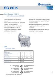
<strong>Incremental</strong> <strong>Encoders</strong> <strong>for</strong> <strong>GR</strong>/G <strong>Motors</strong><br />
Inkrementalgeber für <strong>GR</strong>/G-Motoren<br />
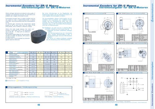
Where stringent demands are placed on the quality of<br />
regulation and positioning accuracy, the DC-motors are<br />
available with a digital incremental encoder.<br />
<strong>Incremental</strong> encoders have no sliding contacts and are<br />
not subject to wear. A light-emitting diode, a slotted<br />
metal disc, and a photo-diode array <strong>for</strong>m a photoelectric<br />
circuit.<br />
An internal logic produces two square-wave signals<br />
phased at 90° to each other from the output of the<br />
photo-diodes, with or without a reference impulse.<br />
Where the cable length between the motor and<br />
encoder is more than 2.5 m, we recommend<br />
use of the RE .. TI, fitted with an additional<br />
power booster.<br />
The standard supply voltage <strong>for</strong> the incremental<br />
encoder is 5 VDC. As specials, 24V versions<br />
are also available.<br />
An IP54 cover is recommended as protection<br />
against external influences.<br />
Data / Leistungsdaten<br />
Operating voltage/<br />
Versorgungsspannung<br />
Impulses per revolution/<br />
Impulszahl pro Umdrehung<br />
Signal rise time/<br />
Signalanstiegszeit<br />
Signal decay time/<br />
Signalabfallzeit<br />
Current consumption/<br />
Stromaufnahme<br />
Output voltage/<br />
Ausgangsspannung (low--level)<br />
Output voltage/<br />
Ausgangsspannung (high-level)<br />
Max. output current/<br />
max. Ausgangsstrom<br />
Operating temperature/<br />
Betriebstemperatur<br />
Protection class/<br />
Schutzart<br />
*) C L =25pF; R= 11kΩ<br />
VDC<br />
ppr<br />
ns<br />
ns*<br />
mA<br />
VDC<br />
VDC<br />
mA<br />
°C<br />
Standard/Standard On request/auf Anfrage<br />
RE 20 S<br />
5<br />
100<br />
200<br />
30<br />
max. 40<br />
max. 0.4<br />
min. 2.4<br />
20<br />
- 40 ... + 80<br />
Wiring suggestions / Schaltungsvorschlag<br />
IP<br />
30<br />
High = cw./rechts<br />
High = ccw./links<br />
Clockwise/counter-cw. detection / Rechts-/Links-Erkennung<br />
RE 30-2<br />
5<br />
100 ... 512<br />
200<br />
50<br />
17 (max. 40)<br />
Bei hohen An<strong>for</strong>derungen an die Regelbarkeit und<br />
Positioniergenauigkeit sind die Gleichstrommotoren mit<br />
einem digitalen Inkrementalgeber erhältlich.<br />
Die Inkrementalgeber arbeiten berührungslos und verschleißfrei.<br />
Eine Leuchtdiode, eine metallische Schlitzscheibe<br />
und ein Fotodiodenarray bilden eine Lichtschranke.<br />
Eine interne Logik erzeugt aus dem Signal der<br />
Fotodioden zwei um 90° verschobene Rechtecksignale,<br />
ohne bzw. mit Referenzimpuls.<br />
Bei Kabellängen von mehr als 2,5 m zwischen Motor<br />
und Geber empfiehlt sich der Einsatz eines RE .. TI,<br />
ausgerüstet mit einem zusätzlichen Leistungstreiber.<br />
Die Versorgungsspannung der Inkrementalgeber<br />
beträgt standardmäßig 5 VDC. In<br />
Sonderausführungen sind auch 24V-Versionen<br />
erhältlich.<br />
Zum Schutz vor äußeren Einflüssen empfiehlt<br />
sich die Verwendung einer IP54-Schutzhaube.<br />
max. 0.4 (3.2 mA) max. 0.4 (3.9 mA) max. 0.5 (20 mA) max. 0.4 (3.9 mA) max. 0.5 (20 mA)<br />
min. 2.4 (40 µA)<br />
-<br />
- 40 ... + 100<br />
48<br />
30<br />
RE 30-3 RE 30-3 TI RE 56-3 RE 56-3 TI<br />
5<br />
500 ... 512<br />
180<br />
40<br />
57 (max. 85)<br />
min. 2.4 (200 µA) min. 2.4 (200 µA) min. 2.4 (200 µA) min. 2.4 (200 µA)<br />
-<br />
- 40 ... + 100<br />
30<br />
5<br />
500 ... 512<br />
180<br />
40<br />
max. 85<br />
70<br />
- 40 ... + 100<br />
30<br />
5<br />
1000<br />
180<br />
40<br />
57 (max. 85)<br />
-<br />
- 40 ... + 100<br />
30<br />
Pulse doubling / Impuls-Verdoppelung<br />
5<br />
1000<br />
180<br />
40<br />
max. 85<br />
70<br />
- 40 ... + 100<br />
30<br />
4 impulses per rev. /<br />
4 Impulse pro Umdrehung<br />
<strong>Incremental</strong> <strong>Encoders</strong> <strong>for</strong> <strong>GR</strong>/G <strong>Motors</strong><br />
Inkrementalgeber für <strong>GR</strong>/G-Motoren<br />
Pin<br />
1<br />
2<br />
3<br />
4<br />
5<br />
Pin<br />
1<br />
2<br />
3<br />
4<br />
5<br />
L<br />
RE 20 (without cover/ ohne Schutzhaube) IP 30<br />
RE 20<br />
GND 0V<br />
-<br />
A<br />
Vcc 5V<br />
B<br />
RE 30 / RE 30 TI (without cover/ ohne Schutzhaube) IP 30<br />
RE 30-X<br />
GND 0V<br />
I (30-3)<br />
A<br />
Vcc 5V<br />
B<br />
Pin<br />
1<br />
2<br />
3<br />
4<br />
5<br />
RE 30-X TI<br />
n.c.<br />
Vcc 5V<br />
GND 0V<br />
n.c.<br />
/A<br />
Pin<br />
6<br />
7<br />
8<br />
9<br />
10<br />
RE 30-X TI<br />
A<br />
/B<br />
B<br />
/I (30-3)<br />
I (30-3)<br />
<strong>GR</strong> 80 + RE 30 / RE 30 TI (+E90) + cover/ Schutzhaube IP 54<br />
RE 30 RE 30 + E90<br />
55 77.5<br />
Pin<br />
1<br />
2<br />
3<br />
4<br />
30-3TI<br />
A<br />
B<br />
Vcc 5V<br />
GND 0V<br />
Pin<br />
5<br />
6<br />
7<br />
8<br />
30-3TI<br />
I<br />
/A<br />
/B<br />
/I<br />
Pin<br />
1<br />
2<br />
3<br />
4<br />
<strong>GR</strong>/E90<br />
Motor (-)<br />
Motor (+)<br />
Asto E (+)<br />
Asto E (-)<br />
49<br />
Pin<br />
1<br />
2<br />
3<br />
4<br />
5<br />
L<br />
RE 56 / RE 56 TI (without cover/ ohne Schutzhaube) IP 30<br />
RE 56-X<br />
GND 0V<br />
I (56-3)<br />
A<br />
Vcc 5V<br />
B<br />
<strong>GR</strong> 63 + RE 30 / RE 30 TI (+E90) + cover/ Schutzhaube IP 54<br />
RE 30 RE 30 + E90<br />
40 79<br />
Pin<br />
1<br />
2<br />
3<br />
4<br />
Pin<br />
1<br />
2<br />
3<br />
4<br />
5<br />
30-3TI<br />
A<br />
B<br />
Vcc 5V<br />
GND 0V<br />
RE 56-X TI<br />
n.c.<br />
Vcc 5V<br />
GND 0V<br />
n.c.<br />
/A<br />
Pin<br />
5<br />
6<br />
7<br />
8<br />
30-3TI<br />
I<br />
/A<br />
/B<br />
/I<br />
Pin<br />
6<br />
7<br />
8<br />
9<br />
10<br />
Pin<br />
1<br />
2<br />
3<br />
4<br />
RE 30-3 (Connection example/ Beschaltungsvorschlag)<br />
RE 56-X TI<br />
A<br />
/B<br />
B<br />
/I (56-3)<br />
I (56-3)<br />
<strong>GR</strong>/E90<br />
Motor (-)<br />
Motor (+)<br />
Asto E (+)<br />
Asto E (-)<br />
Dimension drawings of complete drives (motor and gear) are available at www.dunkermotoren.com (Products -> direct selection)<br />
Maßzeichnungen von kompletten Antrieben (Motor-Getriebe-Kombinationen) erhalten Sie auf unsere Homepage: www.dunkermotoren.de (Produkte -> direkte Produktauswahl)<br />
<strong>Incremental</strong> <strong>Encoders</strong> Inkrementalgeber
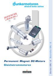
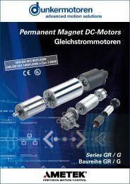
<strong>Incremental</strong> <strong>Encoders</strong> <strong>for</strong> BLDC <strong>Motors</strong><br />
Inkrementalgeber für BG-Motoren<br />
As standard, brushless DC motors of the BG range are<br />
equipped with Hall sensors <strong>for</strong> measuring current motor<br />
speed. Where more stringent demands are placed on<br />
the quality of regulation and positioning accuracy, the<br />
motors are available with a digital incremental encoder.<br />
<strong>Incremental</strong> encoders have no sliding contacts and are<br />
not subject to wear. A light-emitting diode, a slotted<br />
metal disc, and a photo-diode array <strong>for</strong>m a photoelectric<br />
circuit.<br />
An internal logic produces two square-wave signals<br />
phased at 90° to each other from the output of the<br />
photo-diodes, with or without a reference impulse.<br />
Where the cable length between the motor<br />
and encoder is more than 2.5 m, we recommend<br />
use of the RE .. TI, fitted with an additional<br />
power booster.<br />
The standard supply voltage <strong>for</strong> the incremental<br />
encoder is 5 VDC. As specials,<br />
24V versions are also available.<br />
An IP54 cover is recommended as protection<br />
against external influences. In<br />
combination with motor BG 65, the incremental<br />
encoder can be incorporated in the<br />
IP65 extruded motor body.<br />
Data / Leistungsdaten<br />
Operating voltage/<br />
Versorgungsspannung<br />
Impulses per revolution/<br />
Impulszahl pro Umdrehung<br />
Signal rise time/<br />
Signalanstiegszeit<br />
Signal decay time/<br />
Signalabfallzeit<br />
Current consumption/<br />
Stromaufnahme<br />
Output voltage/<br />
Ausgangsspannung (low--level)<br />
Output voltage/<br />
Ausgangsspannung (high-level)<br />
Max. output current/<br />
max. Ausgangsstrom<br />
Operating temperature/<br />
Betriebstemperatur<br />
Protection class/<br />
Schutzart<br />
*) C L =25pF; R= 11kΩ<br />
VDC<br />
ppr<br />
ns<br />
ns*<br />
mA<br />
VDC<br />
VDC<br />
mA<br />
°C<br />
IP<br />
RE 30-2<br />
5<br />
100 ... 512<br />
200<br />
50<br />
17 (max. 40)<br />
max. 0.4 (3.2 mA)<br />
min. 2.4 (40 µA)<br />
-<br />
- 40 ... + 100<br />
30<br />
42<br />
Bürstenlose Gleichstrommotoren der Baureihe BG sind<br />
standardmäßig mit Hallsensoren zur Erfassung des<br />
Drehzahl-Istwertes ausgestattet.<br />
Bei erhöhten An<strong>for</strong>derungen an die Regelbarkeit und<br />
Positioniergenauigkeit sind die Motoren zusätzlich mit<br />
einem digitalen Inkrementalgeber erhältlich.<br />
Die Inkrementalgeber arbeiten berührungslos und verschleißfrei.<br />
Eine Leuchtdiode, eine metallische Schlitzscheibe<br />
und ein Fotodiodenarray bilden eine Lichtschranke.<br />
Eine interne Logik erzeugt aus dem Signal der<br />
Fotodioden zwei um 90° verschobene Rechtecksignale,<br />
ohne bzw. mit Referenzimpuls.<br />
5<br />
500 ... 512<br />
180<br />
40<br />
57 (max. 85)<br />
max. 0.4 (3.9 mA)<br />
min. 2.4 (200 µA)<br />
-<br />
- 40 ... + 100<br />
30<br />
Bei Kabellängen von mehr als 2,5 m zwischen<br />
Motor und Geber empfiehlt sich der Einsatz<br />
eines RE .. TI, ausgerüstet mit einem zusätzlichen<br />
Leistungstreiber.<br />
Die Versorgungsspannung der Inkrementalgeber<br />
beträgt standardmäßig 5 VDC. In Sonderausführungen<br />
sind auch 24V-Versionen erhältlich.<br />
Zum Schutz vor äußeren Einflüssen empfiehlt sich<br />
die Verwendung einer IP54-Schutzhaube. In Kombination<br />
mit dem BG 65 sind die Inkrementalgeber<br />
auch im IP65-Strangpressprofilgehäuse erhältlich.<br />
RE 30-3 RE 30-3 TI RE 56-3 RE 56-3 TI<br />
5<br />
500 ... 512<br />
180<br />
40<br />
max. 85<br />
max. 0.5 (20 mA)<br />
min. 2.4 (200 µA)<br />
70<br />
- 40 ... + 100<br />
30<br />
5<br />
1000<br />
180<br />
40<br />
57 (max. 85)<br />
max. 0.4 (3.9 mA)<br />
min. 2.4 (200 µA)<br />
-<br />
- 40 ... + 100<br />
RE 30/RE 30 TI; RE 56/RE 56 TI Wiring suggestions / Schaltungsvorschlag<br />
High = cw./rechts<br />
High = ccw./links<br />
Clockwise/counter-cw. detection / Rechts-/Links-Erkennung<br />
30<br />
Pulse doubling / Impuls-Verdoppelung<br />
5<br />
1000<br />
180<br />
40<br />
max. 85<br />
max. 0.5 (20 mA)<br />
min. 2.4 (200 µA)<br />
70<br />
- 40 ... + 100<br />
30<br />
4 impulses per rev. /<br />
4 Impulse pro Umdrehung<br />
<strong>Incremental</strong> <strong>Encoders</strong> <strong>for</strong> BLDC <strong>Motors</strong><br />
Inkrementalgeber für BG-Motoren<br />
RE 30<br />
(without cover/ ohne Haube) IP 30<br />
RE 30/ RE 30 TI<br />
(with cover/ mit Haube) IP 54<br />
Pin<br />
1<br />
2<br />
3<br />
4<br />
RE 30/ RE 30 TI<br />
(with BG 65 housing/ mit BG 65 Strangpressprofilgehäuse) IP 65<br />
Pin<br />
1<br />
2<br />
3<br />
RE 30-X (TI)<br />
Vcc 5V<br />
A<br />
B<br />
(I)<br />
BG 65<br />
RE 30-X (TI)<br />
Vcc 5V<br />
A<br />
B<br />
Pin<br />
1<br />
2<br />
3<br />
4<br />
5<br />
Pin<br />
5<br />
6<br />
7<br />
8<br />
Pin<br />
4<br />
5<br />
6<br />
RE 30-X<br />
GND 0V<br />
(I)<br />
A<br />
Vcc 5V<br />
B<br />
RE 30-X (TI)<br />
GND 0V<br />
(/A)<br />
(/B)<br />
(/I)<br />
RE 30-X (TI)<br />
(I)<br />
GND 0V<br />
(/I)<br />
43<br />
RE 30 TI<br />
(without cover/ ohne Haube) IP 30<br />
Pin<br />
1<br />
2<br />
3<br />
4<br />
5<br />
RE 30-X TI<br />
n.c.<br />
Vcc 5V<br />
GND 0V<br />
n.c.<br />
/A<br />
RE 30/ RE 30 TI<br />
(with cover and brake E 90/ mit Haube und Bremse E 90) IP 54<br />
Pin<br />
1<br />
2<br />
3<br />
4<br />
RE 30-X (TI)<br />
Vcc 5V<br />
A<br />
B<br />
(I)<br />
E 90<br />
n.c.<br />
n.c.<br />
+<br />
-<br />
RE 30-3<br />
(Connection example/ Beschaltungsvorschlag)<br />
Pin<br />
6<br />
7<br />
8<br />
9<br />
10<br />
Pin<br />
5<br />
6<br />
7<br />
8<br />
RE 30-X TI<br />
A<br />
/B<br />
B<br />
(/I)<br />
(I)<br />
RE 30-X (TI)<br />
GND 0V<br />
(/A)<br />
(/B)<br />
(/I)<br />
<strong>Incremental</strong> <strong>Encoders</strong> Inkrementalgeber